


-
Trace gases have been proven to be closely related to human life, and the effects of their variations include those on ecology, industrial safety, and human health1–4. Gas sensing technology based on laser spectroscopy has rapidly developed with advances in laser technology5–12. Its advantages include excellent selectivity, high sensitivity, long service life, and applicability across diverse fields13–17. Light-induced thermoelastic spectroscopy (LITES) is an emerging gas sensing technology, which can achieves non-contact and fast measurement of gases and is currently a hot research topic18–24.
LITES is based on the light-induced thermoelastic effect of quartz, which was first reported by Ma et al. in 201825. In LITES, a quartz tuning fork (QTF) is used as a detector to detect changes in the light intensity of the excitation laser after transmission through the target gas. When the laser is incident on the QTF surface, localised thermal deposition occurs to form a microheat source, which results in thermal expansion and stress in the quartz crystal. The arms of the QTF vibrate symmetrically under the stress, and this mechanical deformation is eventually converted into an electrical signal owing to the piezoelectric properties of the quartz crystal26–29. Information on the gas concentration can be obtained by demodulating the electrical signal. In the LITES system, the QTF does not need to be submerged in the target gas, which eliminates the problem of corrosion damage to the QTF while detecting corrosive and acidic gases30–34. Moreover, based on the physical mechanism of the thermoelastic effect, LITES can be used for spectroscopy across a full range of wavelengths and offers better detection sensitivity compared to tunable diode laser absorption spectroscopy (TDLAS) under the same conditions33.
LITES has emerged as a reliable and promising gas-sensing technology. According to Beer–Lambert’s law, increasing both the absorption length and excitation laser intensity effectively enhance the absorption signal. Multipass cells (MPC) provide long absorption lengths in a small volume and are key devices in the field of absorption spectroscopy35,36. Herriott cell, which is structurally stable and easily adjustable, have become the mainstream type37. However, the continuous improvement of system integration necessitates further improvement in the parameters of MPCs, such as mirror utilization and the ratio of the optical path length to the volume (RLV)38,39.
Distributed feedback (DFB) diode lasers are commonly used in LITES systems and are convenient for wavelength modulation. However, they typically have low power (less than 30 mW). Moreover, some mature optical amplifiers, such as erbium-doped fiber amplifiers (EDFAs) and ytterbium-doped fiber amplifiers (YDFAs) are only aimed at the communication band40,41. Fiber amplifiers must cover more wavelengths to meet the spectroscopic detection requirements of different gases.
In this study, a mathematical model based on ray tracing was established to design MPC with dense spot patterns and high RLV. MPCs with four different spot patterns were obtained, and an MPC with four-concentric-circle pattern was selected as the gas chamber for the LITES sensor. Methane (CH4) was chosen as the target gas and its absorption line located at 1.65 μm was selected to exclude interference from other gases. A Raman fiber amplifier (RFA) was used to amplify the optical power. In particular, a low-frequency trapezoidal-tip QTF was employed as a detector to enhance sensing performance.
-
Multiple reflections can easily be achieved between two coaxially placed spherical mirrors, and a circular or elliptical spot pattern can be formed on the mirrors when the laser is incident at a specific angle42,43. The position and number of spots can be calculated from the ABCD matrix in the paraxial approximation, which can be used to construct a Herriott cell for spectroscopic detection. When the laser is incident at a wider angle, more reflections occur, and denser spot distributions are created on the mirrors. Compared with the Herriott cell, the MPC with dense spot patterns allows more reflections at short base lengths with good stability.
Because the conditions of the paraxial approximation are no longer satisfied when the laser is incident at a wide angle, Herriott’s theory cannot accurately calculate the reflection of the beams44–46. Using the law of reflection in the vector form enables accurate and fast ray tracing. In the coordinate system shown in Fig. 1, the incidence position is defined as (x0, y0), while z0 can be determined from the spherical coordinate equation. The angles of incidence are determined by θ and φ which are defined in Fig. 1. Accordingly, the direction vector can be obtained as (sin θ, sin φ, $ \sqrt{\text{1-}{\text{sin}}^{\text{2}}{\theta}\text{-}{\text{sin}}^{\text{2}}{\varphi}} $). Additionally, the distance d between the two mirrors and the radius of curvature R are key parameters.
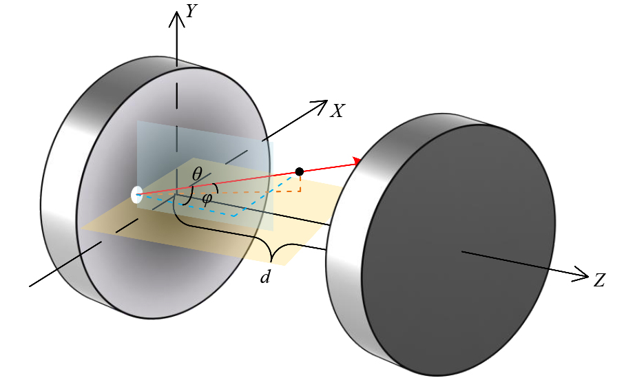
Fig. 1 Schematic of the MPC parameter settings. d: distance between the centre of two mirrors, θ and φ: the angles of incidence.
The positional coordinates of the ith spot, Pi (xi, yi, zi), can be expressed using Eq. 1, in which $ \overrightarrow{{{v}}_{{0}{i}}} $ and di represent the direction vector and single optical path length (OPL) of the incident beam, respectively. According to the law of reflection in vector form, the direction vector of the reflected beam $ \overrightarrow{{{v}}_{{1}{i}}} $ is expressed by Eq. 2. $ \overrightarrow{{{n}}_{{i}}} $ denotes the unit normal vector, which can be obtained by Pi and the sphere centre coordinates Oi, as shown in Eq. 3. In the triangle formed by Pi-1, Pi and Oi, the expression for di can be easily obtained from the cosine theorem, as shown in Eq. 4.
$$ {{P}}_{{i}}={{P}}_{{i}{\text -}{1}}+{{d}}_{{i}}{\cdot}\overrightarrow{{{v}}_{{0}{i}}} $$ (1) $$ \overrightarrow{{{v}}_{{1}{i}}}=\overrightarrow{{{v}}_{{0}{i}}}-{2}\left(\overrightarrow{{{v}}_{{0}{i}}}{\cdot}\overrightarrow{{{n}}_{{i}}}\right){\cdot}\overrightarrow{{{n}}_{{i}}} $$ (2) $$ \overrightarrow{{{n}}_{{i}}}=\left({{O}}_{{i}}-{{P}}_{{i}}\right){/}{R} $$ (3) $$ {{d}}_{{i}}=\sqrt{{{R}}^{{2}}-{\left|\overrightarrow{{{P}}_{{i}{\text -}{1}}{{O}}_{{i}}}\right|}^{{2}}+{\left(\overrightarrow{{{P}}_{{i}{\text -}{1}}{{O}}_{{i}}}\cdot \overrightarrow{{{v}}_{{0}{i}}}\right)}^{{2}}}+\overrightarrow{{{P}}_{{i}{\text -}{1}}{{O}}_{{i}}}\cdot \overrightarrow{{{v}}_{{0}{i}}} $$ (4) During successive multiple reflections, the iteration of the direction vector satisfies the relationship shown in Eq. 5. The above theory can be used to calculate the positions of all spots, and the total OPL is equal to the sum of all the single OPLs.
$$ \overrightarrow{{{v}}_{{0}{i}}}=\overrightarrow{{{v}}_{{1}{i{\text -}1}}} $$ (5) The MPC with dense spot patterns can be designed by tuning the parameters (x0, y0), θ and φ, d and R, and adhering to certain constraints. Typically, spots on mirrors should not overlap to avoid optical interference. Furthermore, MPCs must have a high RLV to satisfy the requirements of the integrated designs.
A mathematical model was developed to determine suitable parameters. Several parallel lines uniformly distributed along the circumference and radial directions were used to simulate the parallel laser beams, which were traced separately according to the aforementioned theory. The ray tracing of multiple lines simulates spot deformation due to aberrations and facilitates accurate parameter selection. Although the incoming perforation can also serve as an outgoing perforation, exiting from the other side is more favourable for constructing the sensor system. When R was 100 mm and the diameters of the mirrors and perforations were 50.8 mm and 2 mm, respectively. The results of four spot patterns, including independent rings, four-concentric-circle, flower, and six-pointed star, were obtained. The parameters of the developed MPCs are listed in Table 1, where N and (xn, yn) denote the number of reflections and outgoing position of the beam, respectively.
(x0, y0) (mm) θ (°) φ (°) d (mm) N (xn, yn) (mm) OPL (m) RLV (cm−2) a (1.00, 18.10) 5.00 −8.11 142.30 236 (−15.43, −3.42) 33.5 11.9 b (−0.79, 20.43) 4.46 −7.85 137.78 274 (−9.95, −0.69) 37.7 13.8 c (2.42, 16.80) 5.66 −5.85 138.70 212 (−17.32, −2.96) 29.4 10.7 d (5.66, 16.17) 6.47 −7.40 104.94 166 (18.48, 5.26) 17.4 8.4 a: independent rings; b: four-concentric--circle; c: flower; d: six-pointed star Table 1. Parameters of MPCs with dense spot patterns.
The spot patterns simulated by the mathematical model are shown in Fig. 2a−d, which show the patterns on the exit mirrors. Similar spots are observed on the other side. The green circles represent the outgoing positions. The effective utilization area of the mirrors was much larger than the spot distribution of the individual rings in the Herriott cell. The optical systems were constructed using a visible laser, and photographs of the spot patterns are shown in Fig. 2e−h. Both the patterns and number of spots were matched between the simulations and measured results. Although some of the spots were unclear owing to multiple reflections, good agreement was observed between the shapes of the actual spots and those of the simulations.
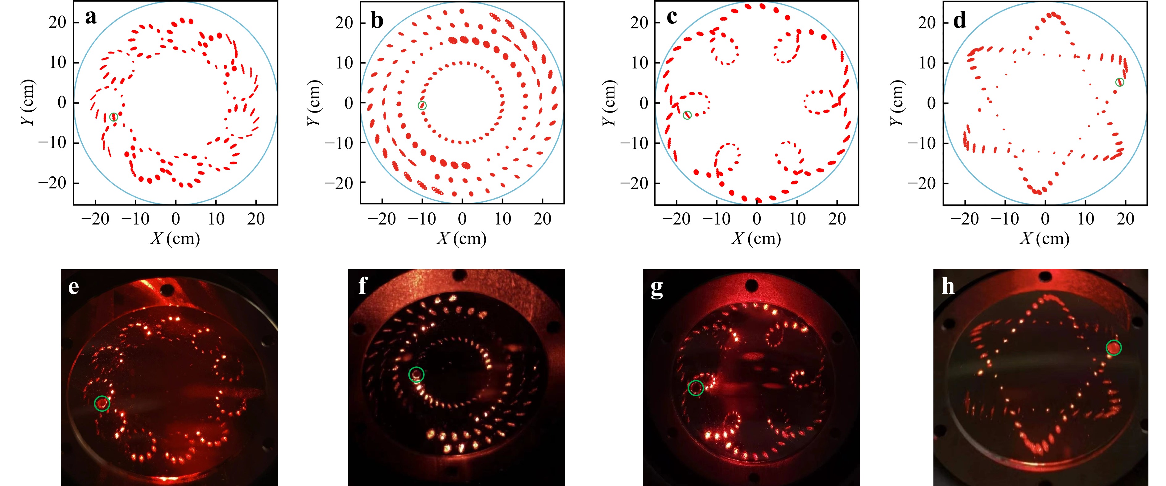
Fig. 2 Simulated and measured spot patterns. a−d: spot patterns simulated by the mathematical model; e−h: photographs of the spot patterns obtained using a visible laser.
-
A system based on direct absorption spectroscopy was constructed and used to verify the OPL of the developed MPCs. The experimental setup is shown in Fig. 3. The near-infrared (NIR) absorption line of CH4 located at 1650.96 nm (6057.08 cm−1) was selected. The operating temperature of the DFB diode laser was set to 35 °C, and it was tuned by a triangular wave with a frequency of 10 Hz. Two wedge-shaped mirrors were used as optical windows to prevent optical interference noise. After passing through the MPCs filled with a 400 ppm CH4:N2 mixture, the laser was focussed by a lens with a focal length of 75 mm and detected using a photodetector (PD). The OPLs of the MPCs were inverted by calculating their absorbance47–49.
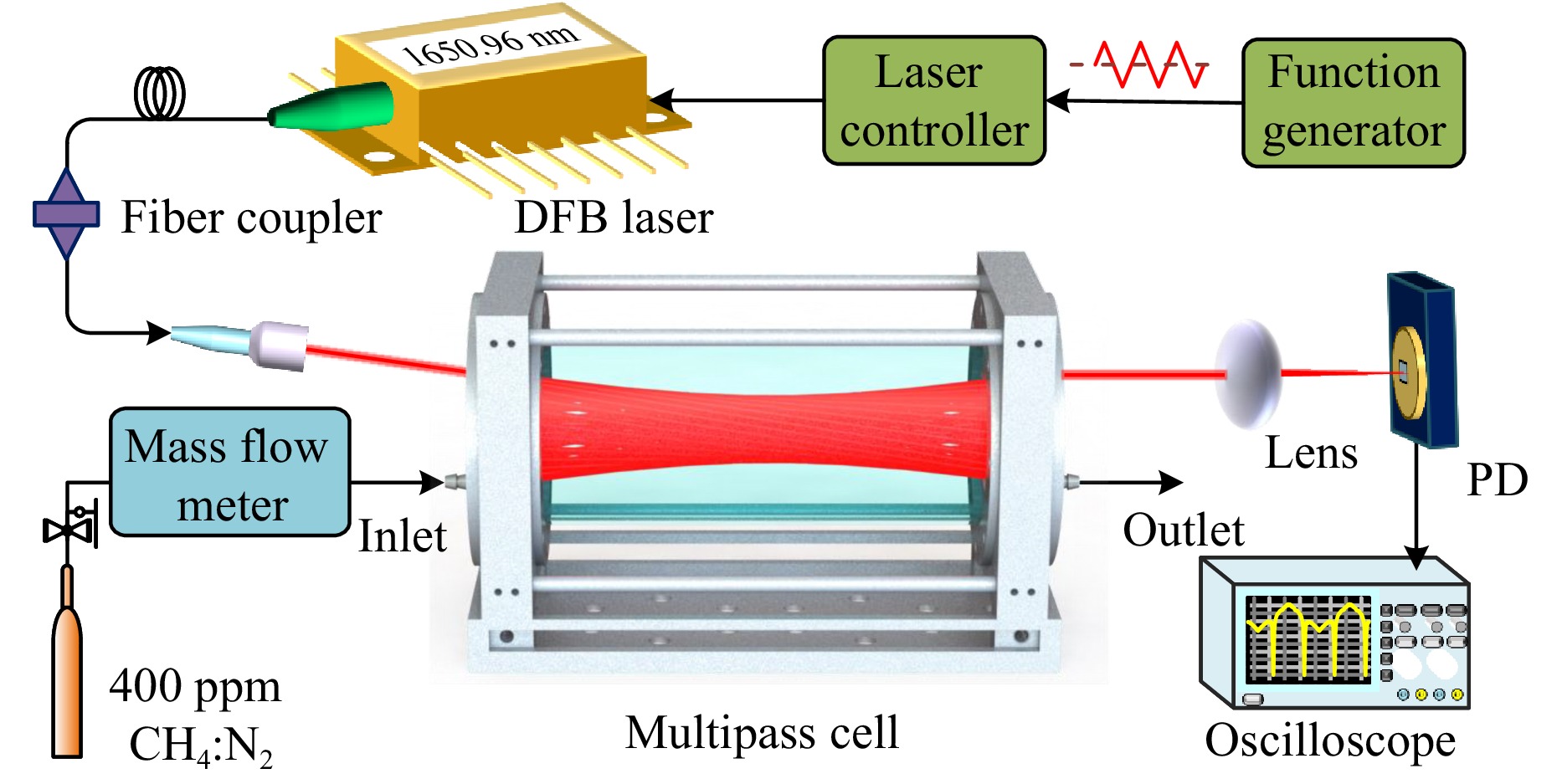
Fig. 3 System used to calibrate the OPLs of MPCs. PD: photodetector.
Fig. 4 shows the CH4 absorbance curves measured at room temperature and atmospheric pressure. Fig. 4a−d correspond sequentially to the four MPCs presented in Table 1, and the raw signals are shown as insets. A Lorentz fit was performed on the measured signals, and the absorbance values at 6057.08 cm−1 were calculated as 0.631, 0.714, 0.553 and 0.323, respectively; the theoretical values obtained from the HITRAN database under the same conditions were 0.625, 0.707, 0.550 and 0.325, respectively. The actual calibrated OPLs of 33.8 m, 38.1 m, 29.6 m and 17.3 m, are close to the theoretical values, and the tiny errors arise from the baseline fitting, Lorentz fitting and environmental perturbations. The developed mathematical model provides an accurate reference for designing MPC with dense spot patterns.
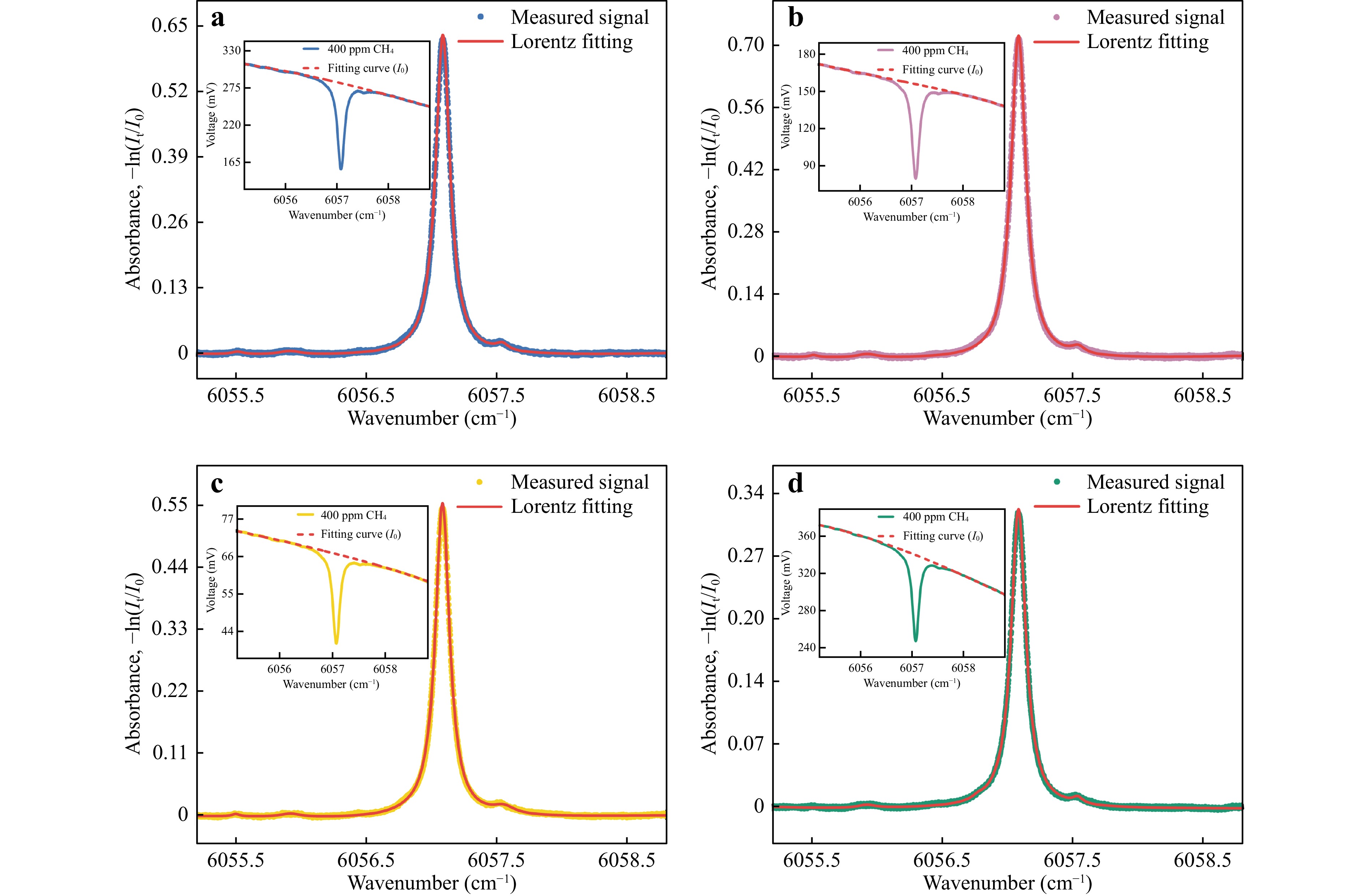
Fig. 4 Measured CH4 absorbance. Insets: Raw signals from direct absorption spectroscopy; a independent rings; b four-concentric-circle; c flower; d six-pointed star.
-
An RFA is an optical amplifier based on stimulated Raman scattering. When the pump and signal lasers are injected into an optical fiber and transmitted simultaneously, owing to the nonlinear effects of the fiber, the pump laser with high power transfers energy to a part of the weak signal laser, and the power of the signal laser is amplified. Theoretically, if the wavelength of the pump laser is appropriately selected, optical signals in the entire wavelength band can be amplified50. In this system, a forward-pumped RFA was used to amplify the power of the excitation laser with 30 mW. The optical power increased to 350 mW after amplification. The measured emission spectra before and after the power amplification are shown in Fig. 5. After amplification by the RFA, the output laser still maintains a good side-mode suppression ratio of >25 dB.
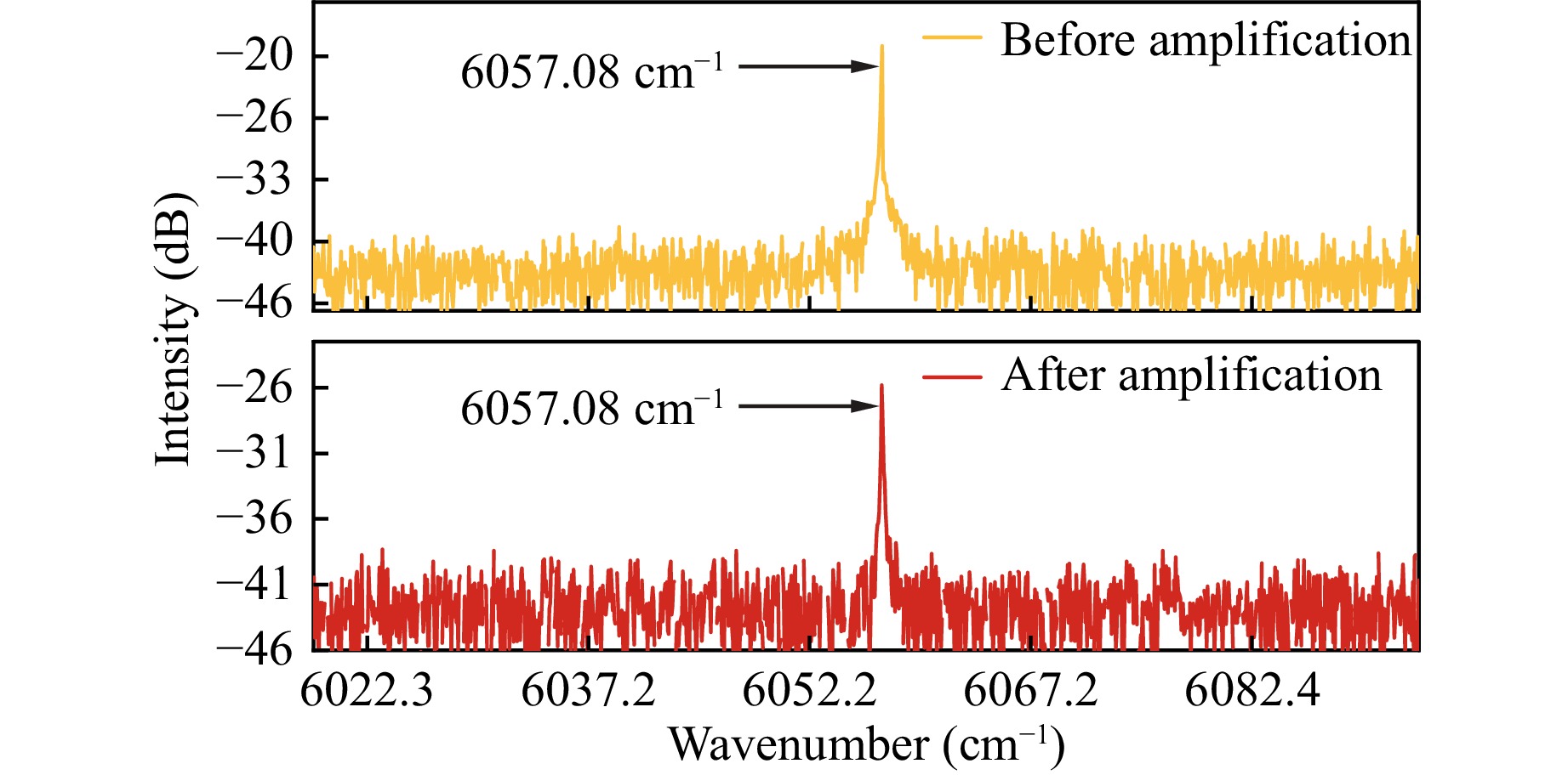
Fig. 5 Emission spectra before and after amplification.
-
The four-concentric-circle pattern MPC with the longest OPL and optimal RLV was chosen to construct the CH4-LITES sensor, and the corresponding experimental setup is shown in Fig. 6. The DFB diode laser was coupled to the RFA using a fiber and subsequently amplified, and the output laser was collimated and incident into the MPC. A plano-convex lens with a focal length of 75 mm was used to focus the emitting laser on the root of the QTF, where it generated the maximum strain field. A trapezoidal-tip QTF with a resonant frequency of 9454.95 Hz was used, which provided a longer energy accumulation time than that of the widely used QTF with a resonant frequency of 32.768 kHz. The enlarged tip of the trapezoidal-tip QTF favours charge generation during resonance, which results in a larger piezoelectric signal level51. Two mass flow meters were used to control the flow rates of a bottle of 400 ppm CH4:N2 gas mixture and a bottle of pure N2. Wavelength modulation spectroscopy and harmonic demodulation techniques were employed to simplify data processing. A triangular wave with a period of 100 s was produced by a signal generator to slowly sweep the output wavelength of the laser through the absorption line, while a high-frequency sine wave generated by a lock-in amplifier was used to modulate the laser. The signal generated by the QTF was demodulated using the lock-in amplifier to obtain the second-harmonic signal (2f). The sine wave frequency was set to half the resonant frequency of the QTF to obtain the maximum response signal.
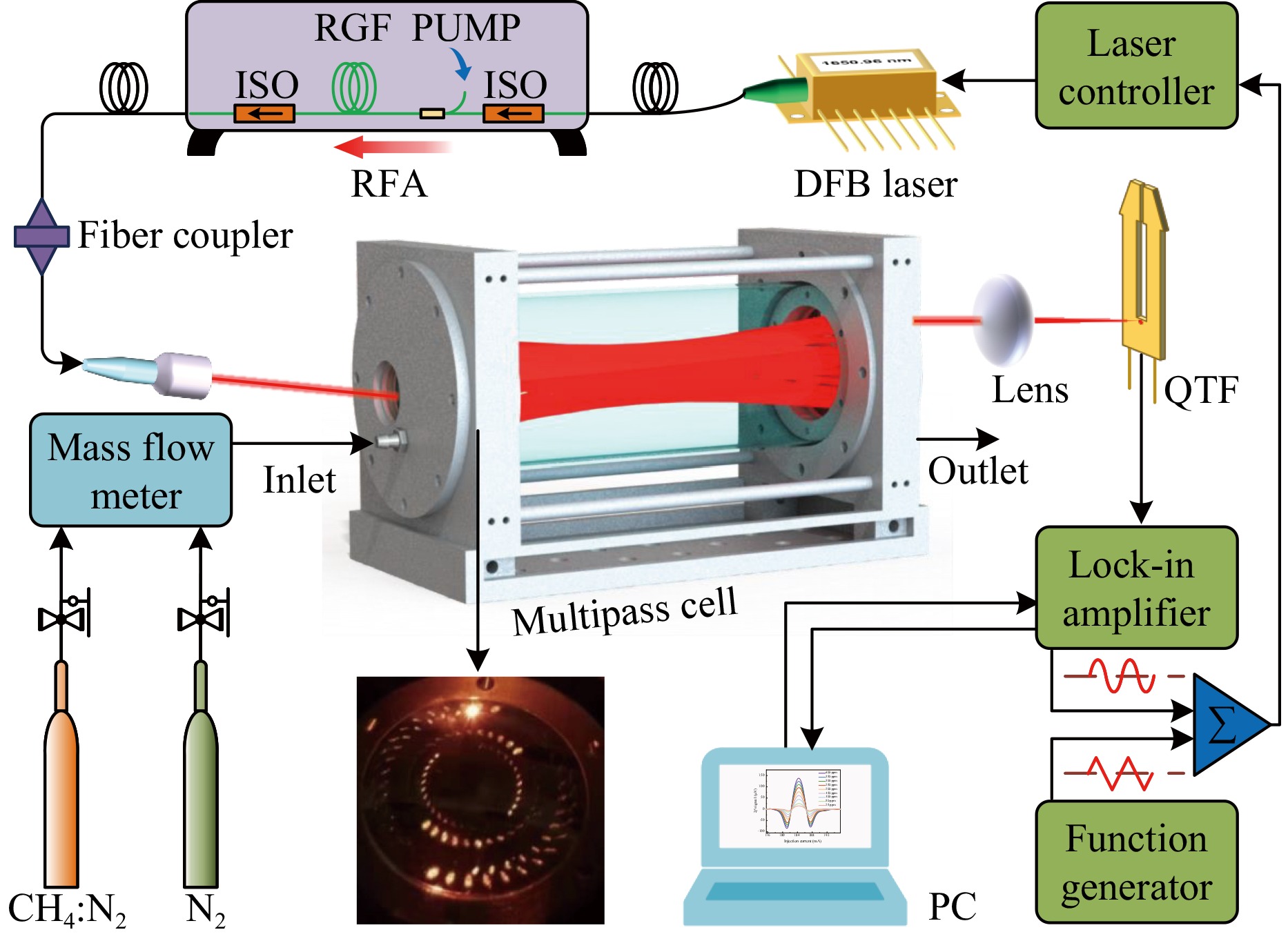
Fig. 6 Schematic of the MPC-based CH4-LITES sensor platform. RFA: Raman fiber amplifier, ISO: Isolator, RGF: Raman gain fiber, QTF: Quartz tuning fork, PC: Personal computer.
-
The resonant frequency of the QTF determines the modulation frequency of the system. The measured resonant frequency curve of the QTF used in the laser excitation method is shown in Fig. 7. The measured signal was squared normalised and Lorentz fitted, and the center frequency (f0) was 9454.95 Hz with a response bandwidth (Δf) of 0.81 Hz. Using the equation $Q=f_0/\Delta f $, the Q-factor of the QTF was calculated to be 11673. The trapezoidal-tip QTF exhibits a narrower response bandwidth than commercial QTFs, resulting in a high Q-factor even at a low resonant frequency.
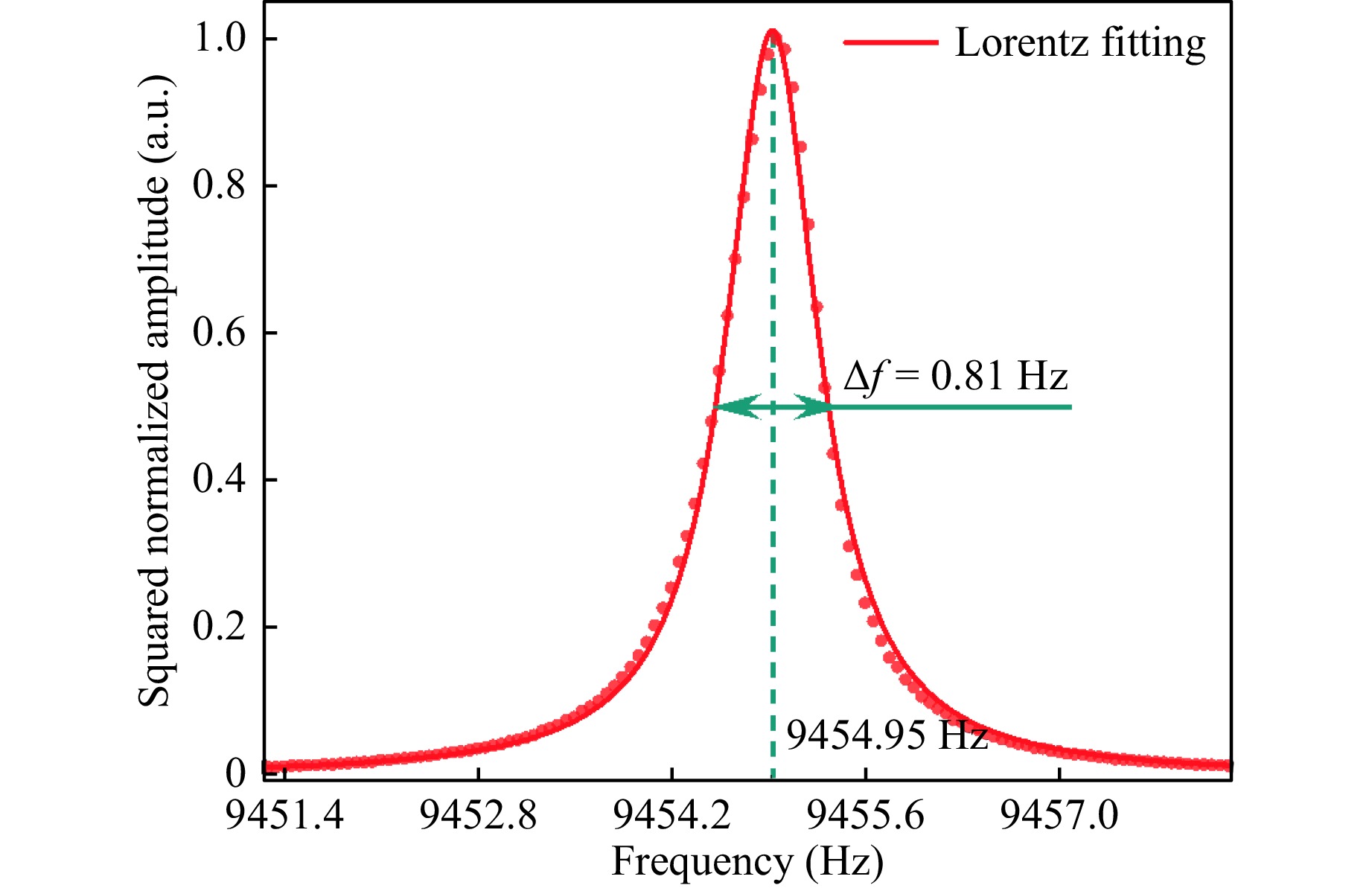
Fig. 7 Resonant frequency curve of the trapezoidal-tip QTF.
The modulation depth of the laser wavelength affected the signal amplitude of the LITES sensor. The 2f signal amplitude at the absorption line, monitored by sweeping the modulation depth, is shown in Fig. 8. The signal level first increases and then decreases, attaining a maximum value at a modulation current of 5.75 mA. This optimum value was used in the subsequent experiments.
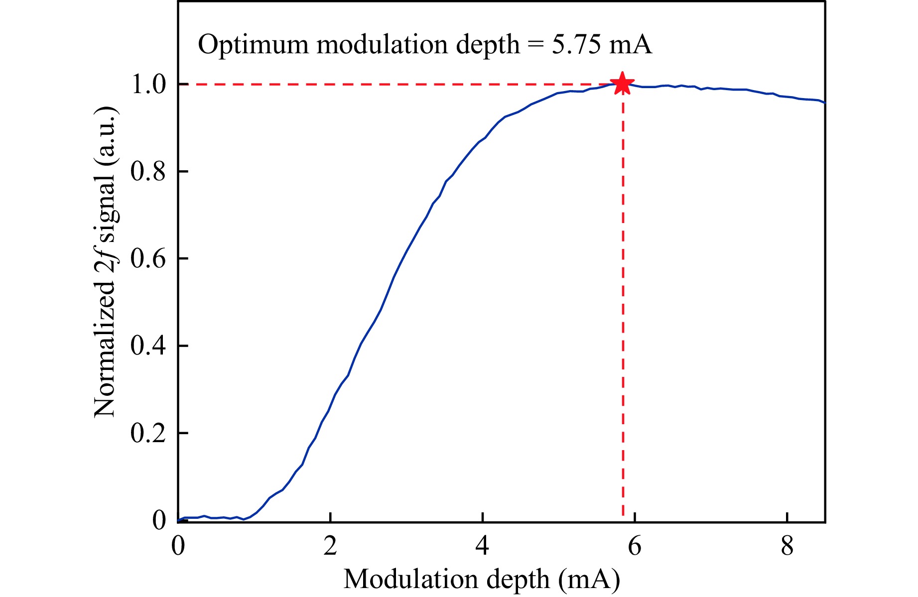
Fig. 8 2f amplitude versus laser modulation current.
The signals of the CH4-LITES sensor were investigated at different RFA output powers that were adjusted to be in the range of 100–350 mW. For the measurement, the integration time of the lock-in amplifier was set to 200 ms, and the order of the filter was fourth. The corresponding detection bandwidth of the system was 346.2 mHz. Fig. 9a shows the 2f peak values obtained at different optical powers, the inset shows the 2f curves. Fig. 9b shows the noise and signal-to-noise ratio (SNR) at different powers. The signal values and SNR were linearly fitted, and R-square for both curves reached 0.99, indicating that both the signal and SNR of the system were linearly related to the output power of the RFA. The SNR was maximised when the RFA output power was 350 mW. Therefore, the subsequent experiments were performed under these conditions.
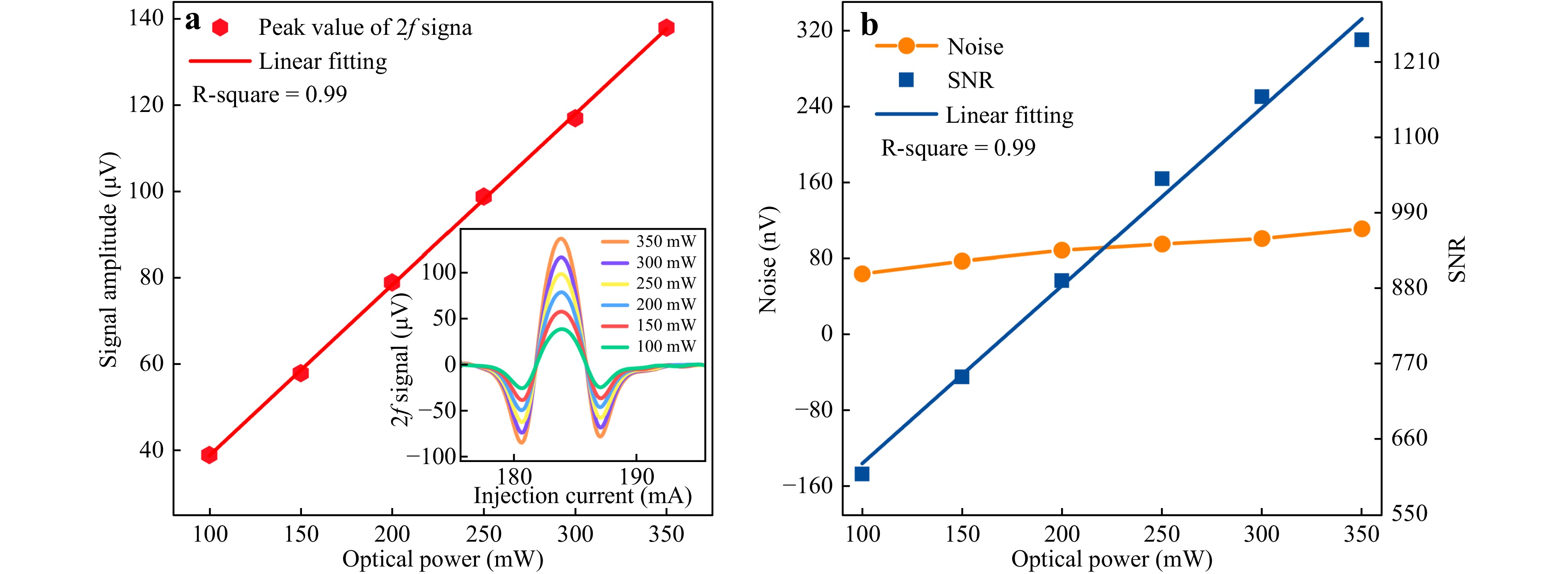
Fig. 9 Optical power response of the CH4-LITES sensor. a 2f peak values at different optical powers. Inset: the 2f curves; b Noise and SNR at different powers.
To verify the CH4-LITES sensor performance based on absorption enhancement, the 2f signals at different concentrations were measured. The gas flow rates were controlled using two mass flow meters to obtain CH4 gas at different concentrations. The total flow rate was 240 mL/min. Fig. 10a, b show the 2f curves measured at different concentrations and a linear fit to the peak values, respectively. The concentrations of CH4 and the signal amplitudes exhibit an excellent linear relationship, with a fitted R-square of 0.99. At 400 ppm, the peak value of the 2f signal is 137.96 μV. The noise measured under a pure N2 background is shown in Fig. 10c. Its standard deviation of 111.07 nV was considered as the noise level of the system. Under these conditions, the minimum detection limit (MDL) of the system was 322 ppb. The normalized equivalent-noise absorption coefficient (NNEA) of the system was calculated as 9.01 × 10⁻⁹ cm−1·W·Hz−1/2 using the equation NNEA = αmin·P·Δf−1/2, where αmin, P, and Δf denote the minimum optical absorption coefficient, effective excitation power of the laser, and detection bandwidth, respectively. This value is comparable to the results of conventional LITES systems.
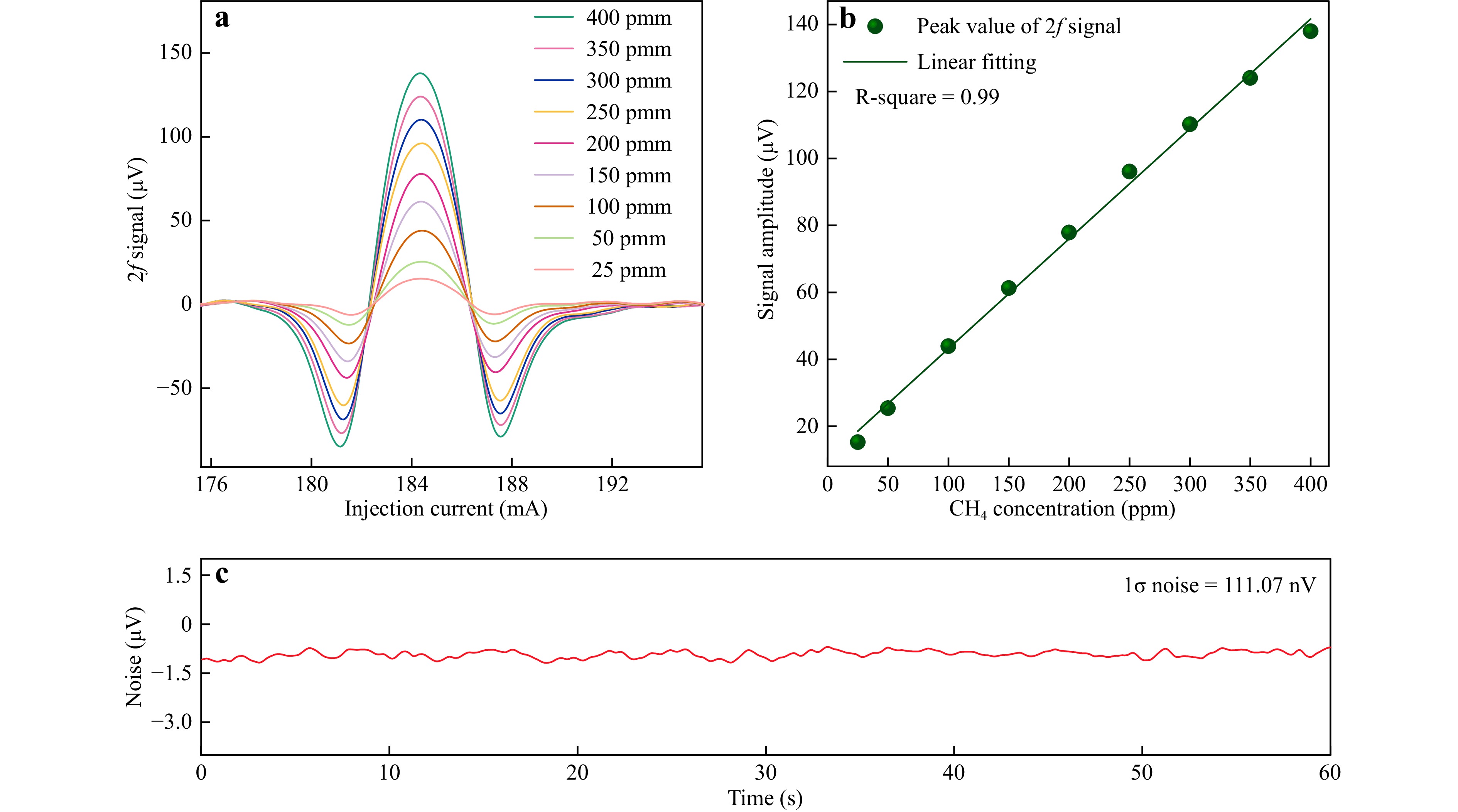
Fig. 10 Concentration response of the CH4-LITES sensor. a 2f curves measured at different concentrations; b Function relationship between different concentrations and the peak value of the 2f signals; c Noise level with a pure N2 background.
The Allan deviation was used to evaluate the long-term stability of the CH4-LITES sensor. The signal level of the system was continuously monitored for more than two hours under a pure N2 atmosphere. The Allan deviation of the system after data processing is shown in Fig. 11. When the average time was 100 s, the MDL of the system improved further to 59.5 ppb. Table 2 compares the performances of the reported CH4-LITES sensors. This study achieved the best detection performance in the NIR band, which surpassed the results obtained in the mid-infrared band.
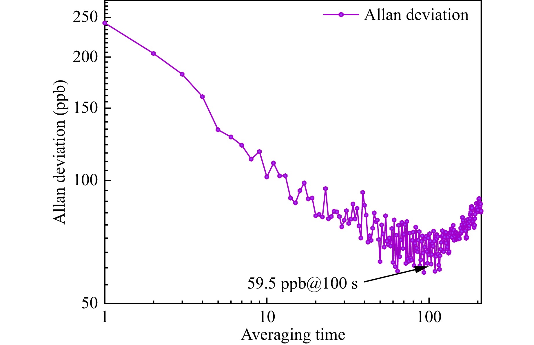
Fig. 11 Allan deviation of the CH4-LITES sensor.
Methods Wave band Wavenumber (cm−1) MDL (ppm) (@ averaging time) Univariate calibrating LITES 52 Mid-infrared 2988.78 0.65 (@ 10 s) S-G filtering LITES 53 Mid-infrared 4294.55 0.5 (@ 0.1 s) MOCAM-LITES 54 Near-infrared 6046.95 0.39 (@ 50 s) LITES21 Near-infrared 6046.95 ~1 (@ 35 s) This work Near-infrared 6057.08 0.059 (@ 100 s) S-G filter: Savitzky-Golay filter; MOCAM: modulation cancellation method. Table 2. Comparison of the detection limits of different CH4-LITES sensors.
-
In conclusion, this manuscript reports on the design of MPC with dense spot patterns and the construction of a CH4-LITES sensor based on a four-concentric-circle pattern MPC and an RFA-amplified diode laser. A mathematical model based on the law of reflection in vector form was established for ray tracing and for obtaining the design parameters of the MPCs. Four novel MPCs with excellent spot patterns were developed and the actual OPLs were verified to be consistent with the theoretical results. An MPC with a four-concentric-circle pattern achieved an effective absorption path of approximately 38 m over a space of approximately 14 cm in physical length, with an RLV as high as 13.8 cm−2. An RFA was used to amplify the optical power to 350 mW for a diode laser with an emission wavelength of approximately 1651 nm. After amplification, the output laser maintained a good side mode suppression ratio of > 25 dB. A novel trapezoidal-tip QTF was used as the detector to further improve sensing performance. This CH4-LITES sensor exhibited an excellent linear response to optical power and CH4 concentration. The MDL of the sensor was 322 ppb. According to the Allan deviation, the MDL was further reduced to 59.5 ppb when the averaging time was 100 s. The development of new MPCs will facilitate the development of highly sensitive LITES-based sensors, particularly for system miniaturization.
-
The authors thank the National Natural Science Foundation of China (Grant Nos. 62335006, 62022032, 62275065, and 61875047), Key Laboratory of Opto-Electronic Information Acquisition and Manipulation (Anhui University), Ministry of Education (Grant No. OEIAM202202), and the Fundamental Research Funds for Central Universities (Grant No. HIT.OCEF.2023011).
Design of multipass cell with dense spot patterns and its performance in a light-induced thermoelastic spectroscopy-based methane sensor
- Light: Advanced Manufacturing 6, Article number: 1 (2025)
- Received: 22 April 2024
- Revised: 30 September 2024
- Accepted: 08 October 2024 Published online: 17 January 2025
doi: https://doi.org/10.37188/lam.2025.001
Abstract: In this study, a ray tracing model based on the law of reflection in vector form was developed to obtain the design parameters of multipass cells (MPC) with dense spot patterns. Four MPCs with distinct patterns were obtained using an established mathematical model. An MPC with a four-concentric-circle pattern exhibited the longest optical path length (OPL) of approximately 38 m and an optimal ratio of optical path length to volume (RLV) of 13.8 cm-2. A light-induced thermoelastic spectroscopy (LITES)-based methane (CH4) sensor was constructed for the first time using the developed optimal MPC and Raman fiber amplifier (RFA). A novel trapezoidal-tip quartz tuning fork (QTF) was used as the detector to further improve the sensing performance. The CH4-LITES sensor exhibited an excellent linear response to optical power and CH4 concentration. The minimum detection limit (MDL) of the CH4-LITES sensor reached 322 ppb when the output optical power of the RFA was 350 mW. The Allan deviation of the system indicated that the MDL decreased to 59.5 ppb when the average time was increased to 100 s.
Research Summary
Absorption enhancement: Design of multipass cell with dense spot patterns and its performance in LITES-based sensor
Multipass cell (MPC) is a type of optical device used to increase the optical path length of gas absorption. It significantly increases the effective length of the laser-gas interaction in a small volume thereby enhancing the absorption signal. Yufei Ma and colleagues from Harbin Institute of Technology in China now report a mathematical model for MPC designing. Based on this model, they developed several MPCs with dense spot patterns and carried out sensor performance studies of them. A near-infrared methane LITES sensor based on a Raman fiber amplifier and a MPC with dense spot pattern was constructed, and excellent detection performance was achieved. This work is favorable to the development of high-sensitivity laser spectroscopy gas sensors, which is expected to bring new applications in areas such as industrial monitoring and fire warning.
Rights and permissions
Open Access This article is licensed under a Creative Commons Attribution 4.0 International License, which permits use, sharing, adaptation, distribution and reproduction in any medium or format, as long as you give appropriate credit to the original author(s) and the source, provide a link to the Creative Commons license, and indicate if changes were made. The images or other third party material in this article are included in the article′s Creative Commons license, unless indicated otherwise in a credit line to the material. If material is not included in the article′s Creative Commons license and your intended use is not permitted by statutory regulation or exceeds the permitted use, you will need to obtain permission directly from the copyright holder. To view a copy of this license, visit http://creativecommons.org/licenses/by/4.0/.

 DownLoad: