


-
Gas-sensing technology plays an indispensable role in fields such as environmental monitoring, industrial safety, and medical diagnosis1,2. In these fields, demand for sensing systems capable of simultaneously detecting multiple gas components in practical applications is high. For instance, the combined monitoring of methane (CH4) and acetylene (C2H2) can provide an early warning indicator of natural gas leaks3,4. However, traditional single-gas sensors struggle to satisfy the analytical demands of such complex scenarios5–10. Therefore, the development of high-precision, highly selective, and low-cost multi-gas sensors for simultaneous detection is crucial11–18.
Among various gas-detection technologies, laser spectroscopy-based detection has attracted significant interest owing to its high sensitivity, excellent selectivity, and fast response19–26. Quartz-enhanced photoacoustic spectroscopy (QEPAS) was developed by Professor Tittel's research group at Rice University in 200227. This method employs a quartz tuning fork (QTF) as an acoustic wave sensor28–34. Owing to the high Q factor, millimetre-sized dimensions, and low cost (<$1) of a QTF, QEPAS offers significant advantages, including high sensitivity, small volume, and low cost, thus leading to its widespread adoption35–39. However, in QEPAS, the QTF must come into direct contact with the target gas, making it a contact-based measurement technique. This limits its applicability in harsh environments, such as those involving acidic or corrosive gases, or high temperatures, where the performance of the QTF can degrade, ultimately resulting in sensor failure. To overcome these limitations, Ma et al. introduced light-induced thermoelastic spectroscopy (LITES) in 201840. LITES detects the vibration of a QTF induced by the periodic thermal effect resulting from gas molecules absorbing modulated laser light41–46. Compared with QEPAS, LITES offers unique advantages. It not only eliminates the need for an acoustic resonance cavity, avoiding frequency shifts and quality factor limitations caused by cavity effects, but also significantly simplifies the system structure and reduces sensitivity to environmental acoustic noise and mechanical vibration. Moreover, because the QTF does need not be exposed to the gas being measured, it is a non-contact measurement method that is particularly suitable for harsh environments, such as those involving corrosive substances or high temperatures47–52. LITES has been successfully applied in various fields, including greenhouse gas monitoring, toxic gas warning, and trace explosive detection, demonstrating broad application prospects53–56.
Time-division multiplexing (TDM) and frequency-division multiplexing (FDM) are two mainstream approaches in the current research on LITES technology for multi-gas simultaneous detection57–62. TDM performs time-shared measurements by switching laser wavelengths, making true real-time simultaneous detection unachievable and constraining dynamic response performance due to switching speed restrictions57. Although FDM enables simultaneous measurement, it typically requires independent QTF sensing units and corresponding demodulation circuits for each gas, leading to increased system complexity and higher costs58. Recent studies have attempted to implement dual-channel detection by exploiting different vibration modes of a single QTF, such as the fundamental and first overtone flexural modes, as well as simultaneously exciting in-plane and out-of-plane symmetric fundamental flexural modes59–62. However, these schemes still rely on multiple reference sources directly corresponding to the vibration frequencies at the signal demodulation stage. Thus, they fail to address the fundamental problem of complex multi-frequency synchronization and demodulation architecture. In contrast to conventional FDM, which requires a lock-in amplifier to simultaneously handle multiple distinct reference frequencies, the proposed MHD scheme unifies all channels to a single intermediate frequency, thereby eliminating multi-frequency synchronization complexity. Moreover, owing to the lack of an efficient frequency-domain isolation mechanism, inter-channel crosstalk remains a factor that constrains the detection accuracy to some extent.
This paper presents a novel dual-gas LITES (DG-LITES) sensor that employs a mixed-frequency heterodyne demodulation (MHD) method. Using an FDM mechanism, the sensor cooperatively utilises both the fundamental (f0) and first overtone (f1) vibrational modes of a single QTF to establish a dual-channel detection system. The MHD method is introduced to down-convert photothermal signals at different frequencies onto a unified intermediate-frequency carrier, thereby enabling simultaneous dual-channel lock-in demodulation. The core value of this scheme lies in transforming the dependence of dual-channel demodulation on 'multiple high-frequency reference sources' into a reliance on a 'single intermediate frequency reference', significantly reducing the complexity of system synchronisation and laying a solid foundation for the future application of dedicated integrated demodulation circuits. In experiments, CH4 and C2H2 were selected as target gases to validate the performance of the sensor.
-
A schematic diagram of the DG-LITES sensor is shown in Fig. 1a. The beams emitted by the two lasers are combined using a wavelength-division multiplexer (WDM) and directed into the gas cell. After interacting with the target gases, the combined beam is focused by a lens onto the QTF, inducing a corresponding current signal I(t) that correlates with the gas concentration. This current signal I(t) contains both fundamental (f0) and first overtone (f1) frequency components. The current signal is amplified using a custom-designed transimpedance amplifier, resulting in a voltage signal, Va(t), with an enhanced amplitude. Subsequently, Va(t) is split into two parallel paths: one passes through a low-pass filter (LPF) to generate signal Vb(t), and the other passes through a high-pass filter (HPF) to generate signal Vc(t), thereby separating the f0 and f1 components. Reference signals Vd(t) and Ve(t) are then introduced into Mixer 2 and Mixer 1, where they are mixed with Vb(t) and Vc(t), respectively, producing mixed signals Vf(t) and Vg(t) to achieve the required frequency spectrum translation. Finally, the two mixed signals are fed into a lock-in amplifier (LIA) for quadrature demodulation. This process effectively filters out non-target signals and outputs high signal-to-noise ratio (SNR) signals, Vm(t) and Vn(t), enabling the accurate calculation of gas concentrations.
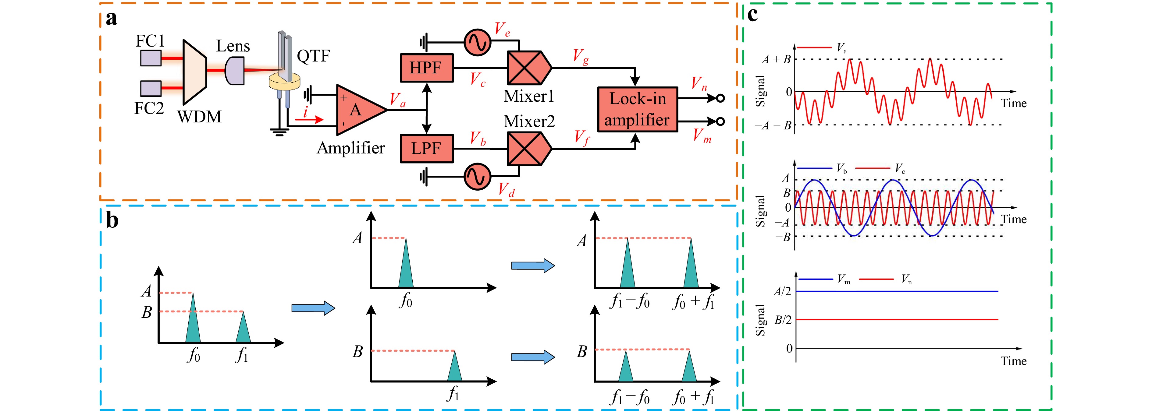
Fig. 1 Principle of the DG-LITES sensor. a Method. b signal in the frequency domain. c signal in the time domain (Va(t): amplified composite signal; Vb(t): fundamental signal processed by the LPF; Vc(t): first overtone signal processed by the HPF; Vm(t): final demodulated output amplitude related to CH4 concentration; Vn(t): final demodulated output amplitude related to C2H2 concentration.
Fig. 1b illustrates the signal transformation process in the frequency domain. The left panel shows the original frequency spectrum of the amplified signal from the QTF after it passes through the custom-designed amplifier, which contains a fundamental signal at f0 with peak amplitude A and the first overtone signal at f1 with peak amplitude B. The middle panel shows the frequency spectra after the amplified signal passes through the LPF and HPF. The right panel shows the frequency spectra after the mixing operation, where two new components are generated at frequencies f1 + f0 and f1 − f0. Fig. 1c shows the evolution of the signal waveforms in the time domain. The upper section shows the amplified signal Va(t) from the self-designed amplifier, following the QTF output. The middle section shows the signals Vb(t) and Vc(t) obtained after processing using the LPF and HPF, respectively. The lower section presents the final output signals, Vm(t) and Vn(t), after demodulation by the LIA.
When the QTF is photothermally excited at its fundamental f0 (corresponding to CH4) and first overtone f1 (corresponding to C2H2), the output current signal I(t) can be expressed as
$$ I(t)={I}_{0}\sin ({\omega }_{0}t+{\varphi }_{0})+{I}_{1}\sin ({\omega }_{1}t+{\varphi }_{1}) $$ (1) where I0 and I1 are the amplitudes of the current signals at frequencies f0 and f1, respectively, and φ0 and φ1 are the initial phases.
This weak current signal is then amplified by the self-designed amplifier with gain G, resulting in a voltage signal Va(t):
$$ {V}_{a}(t)=A\sin ({\omega }_{0}t+{\varphi }_{0})+B\sin ({\omega }_{1}t+{\varphi }_{1}) $$ (2) where A = G·I0 and B = G·I1.
To separate these two frequency signals, Va(t) is split into two paths and processed by an LPF and HPF, respectively, to suppress the unwanted components. Assuming ideal filter characteristics for simplicity, the filtered signals Vb(t) and Vc(t) can be approximated as follows:
$$ \begin{cases} {V}_{b}(t)=A\sin ({\omega }_{0}t+{\varphi }_{0})\\ {V}_{c}(t)=B\sin ({\omega }_{1}t+{\varphi }_{1}) \end{cases} $$ (3) The key step in the MHD method is frequency conversion. The signal Vb(t) is mixed with the reference signal Vd(t) = 2sin(ω1t + φ2) in Mixer 2, while the signal Vc(t) is mixed with the reference signal Ve(t) = 2sin(ω0t + φ3) in Mixer 1. The output signals from the mixers are given by
$$ \begin{cases} \begin{aligned}{V}_{f}(t)=\;&A\cos \left[({\omega }_{1}-{\omega }_{0})t+{\varphi }_{2}-{\varphi }_{0}\right]\\&-A\cos \left[({\omega }_{0}+{\omega }_{1})t+{\varphi }_{0}+{\varphi }_{2}\right]\end{aligned}\\ \begin{aligned}{V}_{g}(t)=\;&B\cos \left[({\omega }_{1}-{\omega }_{0})t+{\varphi }_{3}-{\varphi }_{1}\right]\\&-B\cos \left[({\omega }_{0}+{\omega }_{1})t+{\varphi }_{1}+{\varphi }_{3}\right]\end{aligned} \end{cases} $$ (4) Subsequently, the signals Vf(t) and Vg(t) are separately fed into the two independent input channels of the dual-channel LIA. The LIA uses the sum frequency f1+f0 as the reference frequency and performs synchronous demodulation of the input signals of each channel through its internal phase-sensitive detector, thereby extracting the in-phase (X) and quadrature (Y) components relative to the reference signal. Finally, by calculating the signal amplitude, R = $ \sqrt{{X}^{2}+{Y}^{2}} $, the sensor output voltages Vm(t) and Vn(t) corresponding to the CH4 and C2H2 gas concentrations are obtained using the following expressions:
$$ \begin{cases} {V}_{m}(t)=\dfrac{A}{2}\\ {V}_{n}(t)=\dfrac{B}{2} \end{cases} $$ (5) In the MHD-WMS architecture, phase synchronisation need not be maintained between the modulation signals that drive the lasers (with frequencies f0/2 and f1/2) and the reference signals for the mixers (with frequencies f0 and f1). The LIA uses the sum frequency (f0 + f1) as a reference and performs demodulation by extracting the amplitude of the input signal. This amplitude detection mechanism is insensitive to fixed phase differences, thereby relaxing the stringent requirements for phase locking in the system. In addition, the MHD scheme enables low-crosstalk detection, which can be attributed to the synergistic combination of filtering, frequency mixing, and single-frequency lock-in demodulation. As illustrated in Fig. 1b, the composite signal Va(t) is first separated into its fundamental (f0) and first overtone (f1) components using a 4th-order Butterworth LPF and HPF, respectively. These two filters provide strong stopband attenuation at non-target frequencies, effectively suppressing the majority of the out-of-band crosstalk and ensuring preliminary isolation between the two channels. Subsequently, the filtered signals Vb(t) (primarily containing the f0 component) and Vc(t) (primarily containing the f1 component) are individually mixed with the reference signals at frequencies f1 and f0, respectively. This mixing operation performs a critical frequency translation: Any residual crosstalk component that may have survived the initial filtering stages is also translated by the mixers. However, after mixing, these residual components no longer reside at the target intermediate frequency of f0 + f1 but instead shift to other frequencies. Finally, the mixed signals from both paths are fed into a dual-channel LIA configured for synchronous demodulation at an intermediate frequency of f0 + f1. The internal narrowband low-pass filter of the LIA, which defines the detection bandwidth, only passes the signal components that are phase-locked to this reference frequency. Consequently, any residual crosstalk or noise that falls outside this narrow band around f0 + f1 is deeply suppressed, fundamentally minimising the inter-channel crosstalk in the single-QTF dual-mode sensing system.
-
When performing dual-gas detection in the near-infrared band, the selection of absorption lines requires the systematic consideration of several key parameters to ensure detection performance. First, the absorption line strength is a critical factor in determining the detection sensitivity; characteristic lines with sufficient absorption cross-sections should be selected. Second, spectral specificity is essential; the absorption lines of the target gases should be located away from the absorption regions of common interfering components such as water vapour and carbon dioxide. Additionally, technical feasibility is an important consideration, including the availability of commercial laser sources and the matching between the wavelength modulation depth and absorption linewidth. Based on an analysis of the above parameters and referring to the HITRAN 2020 database, the absorption lines of CH4 and C2H2 were simulated under a temperature of 298 K, pressure of 1 atm, and optical path length of 1 cm across the near-infrared range from 5,800 to 6,700 cm−1, as shown in Fig. 2. Based on these considerations, the CH4 absorption line at 6,057.08 cm−1 and the C2H2 absorption line at 6,534.37 cm−1 were selected as the target absorption lines for detection.
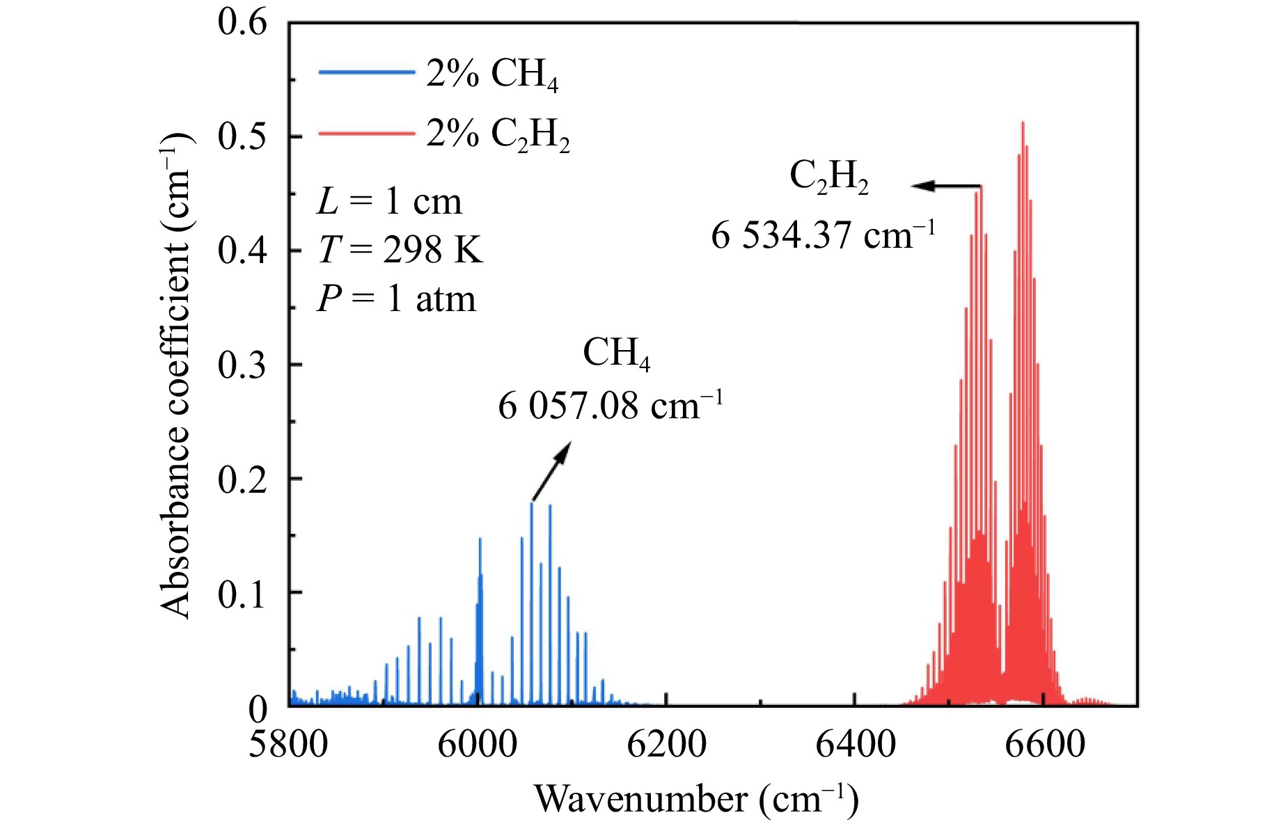
Fig. 2 Simulated absorption spectra of different gases at 5,800–6,700 cm−1.
-
The experimental schematic of the DG-LITES sensor setup is shown in Fig. 3. The sensor primarily consisted of three core parts: an optical section, electronic section, and signal-processing unit, all of which operated together through careful system integration to achieve simultaneous dual-gas detection. The optical section included two continuous-wave distributed feedback (CW-DFB) diode lasers whose centre wavelengths were precisely locked at the characteristic absorption lines of CH4 (1,650.96 nm) and C2H2 (1,530.37 nm). Under optimal operating current and temperature control, their average output powers were and 18 mW, respectively. The long-term wavelength drift was characterised using a wavelength meter, with measured fluctuations of less than ±0.0043 nm for the CH4 laser and less than ±0.0043 nm and ±0.0038 nm for the two lasers used for CH4 and C2H2 detection, respectively. The laser beams were combined using the WDM. After interacting with the target gas, the combined beam was focused onto the base of the self-designed QTF using a lens with a focal length of 50 mm. In the electronic section, the two CW-DFB lasers were driven by independent functional generators. The CH4 channel was modulated at the fundamental frequency (f0) of the QTF, whereas the C2H2 channel was modulated at its first overtone (f1). A self-designed low-noise preamplifier first amplified the composite electrical signal generated by the QTF. The amplified signal was then split into two parallel processing paths: one passes through a self-designed 4th-order Butterworth LPF to extract the fundamental signal and the other passes through a self-designed 4th-order Butterworth HPF to extract the first overtone signal, ensuring the effective separation of the f0 and f1 components. Subsequently, the separated signals were mixed with reference signals at frequencies f1 and f0, respectively. A dual-channel LIA then performed synchronous demodulation on the resulting sum-frequency components (f0 + f1). The DG-LITES sensor incorporated wavelength modulation spectroscopy (WMS) with second-harmonic (2f) detection, enabling the effective suppression of background noise. The system configuration utilised two function generators: Function Generator 1 was dedicated to signal mixing, supplying reference signals sine1 (f0) and sine2 (f1), whereas Function Generator 2 drove laser modulation through its output channels sine3 (f0/2) and sine4 (f1/2). This approach enabled the DG-LITES sensor to process dual-channel signals in parallel using a single reference frequency, thereby significantly simplifying the complex frequency synchronisation architecture typically required in conventional multicomponent detection systems. The signal processing unit employed a Zurich Instruments HF2LI dual-channel LIA for synchronous demodulation. The demodulation frequency of the LIA was set to f0 + f1 = 6,6315.16 Hz, with an input range of ±1 V, a 3rd-order filter, and a time constant of 200 ms. The experimental gas control system comprised a two-channel gas flow controller and two gas cylinders: one containing 2% CH4 in nitrogen (N2), and the other containing 2% C2H2 in N2.
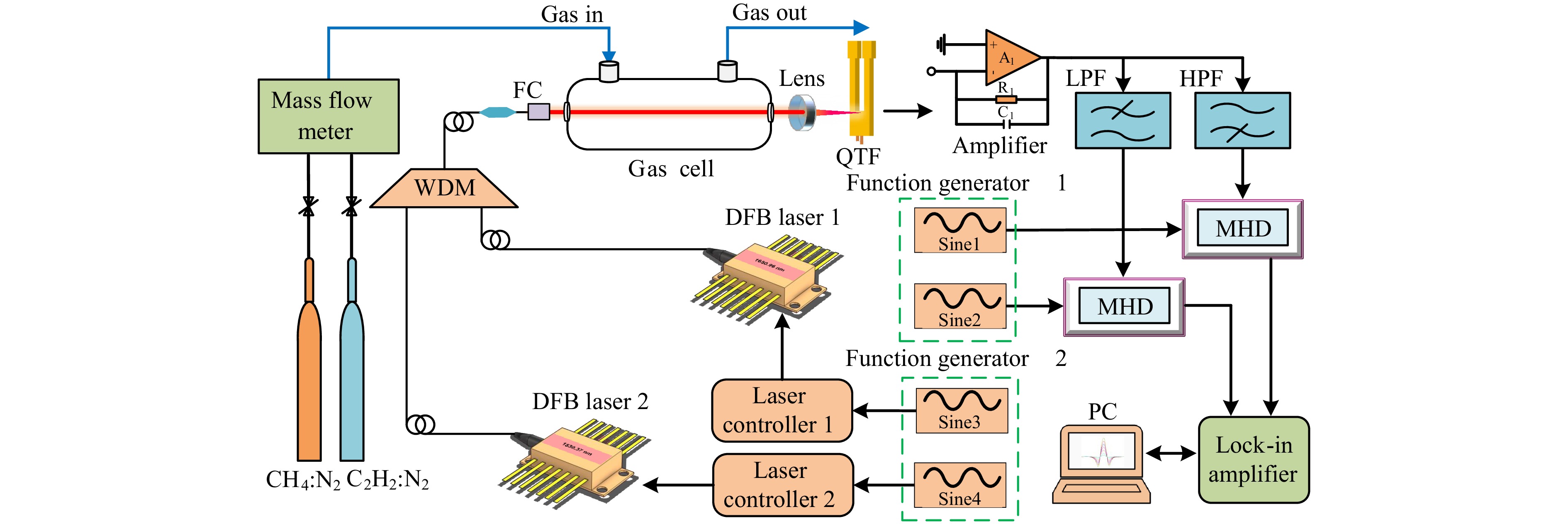
Fig. 3 Experimental schematic diagram of the DG-LITES sensor.
-
The frequency response characteristics of the QTF were investigated using a photoexcitation frequency scanning method. The complete response curve was obtained by precisely sweeping the modulation frequency and simultaneously recording the QTF photothermal response signal. The response data for the fundamental and first overtone frequencies were square-normalised and subsequently fitted using a Lorentzian function, as shown in Fig. 4a, b, respectively. The measured results indicated that both response peaks exhibited a typical Lorentzian line shape with symmetrical profiles. The fundamental response frequency (f0) was identified at 8,758.42 Hz and the first overtone response (f1) at 57,556.74 Hz, with corresponding bandwidths of 1.38 and 129.46 Hz, respectively. Based on these measurements, the Q factors of the fundamental and first overtone were calculated as 6,346.68 and 444.59, respectively. Accurate determination of these response frequencies provided essential parameters for subsequent frequency separation and mixed-frequency demodulation, ensuring effective spectral isolation between the two vibrational modes.
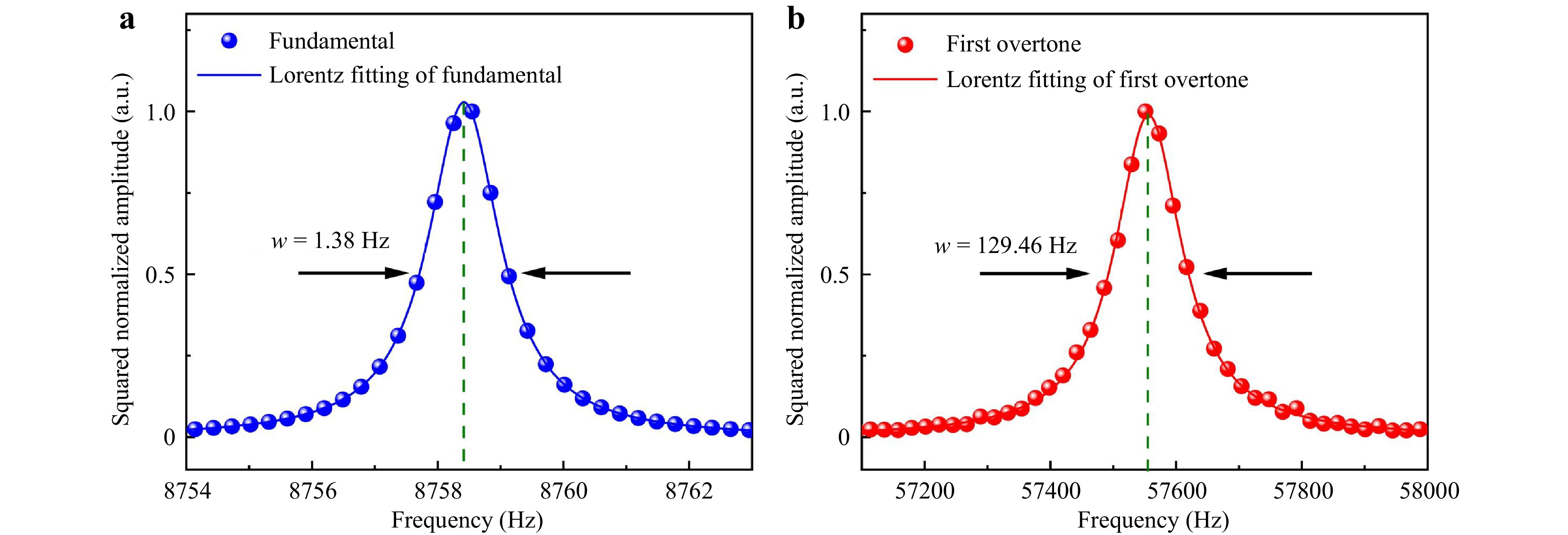
Fig. 4 Frequency response characteristics curve of the used QTF a Fundamental. b First overtone.
Filter bandwidth characterisation was conducted to evaluate the separation performances of the HPF and LPF for the fundamental and first overtone signals. In this system, a fourth-order Butterworth filter was selected for frequency-domain separation primarily because it offers a maximally flat magnitude response in the passband. This ensured that the extracted f0 and f1 component amplitudes from the composite signal were accurate and free from ripple distortions, thereby forming the foundation for subsequent signal processing. A schematic of the bandwidth characterisation is shown in Fig. 5a. Fig. 5b presents the magnitude-frequency responses of both the LPF and HPF. Based on the test results, the LPF exhibited a –3 dB cutoff frequency of 11.54 kHz, with an attenuation of –65.71 dB at f1. The HPF had a –3 dB cutoff frequency of 40.94 kHz, with an attenuation of –60.47 dB at f0. Both filters demonstrated excellent passband characteristics and stopband rejection at the target frequencies, achieving a channel isolation of better than 60 dB. This performance provided a solid hardware foundation for dual gas detection.
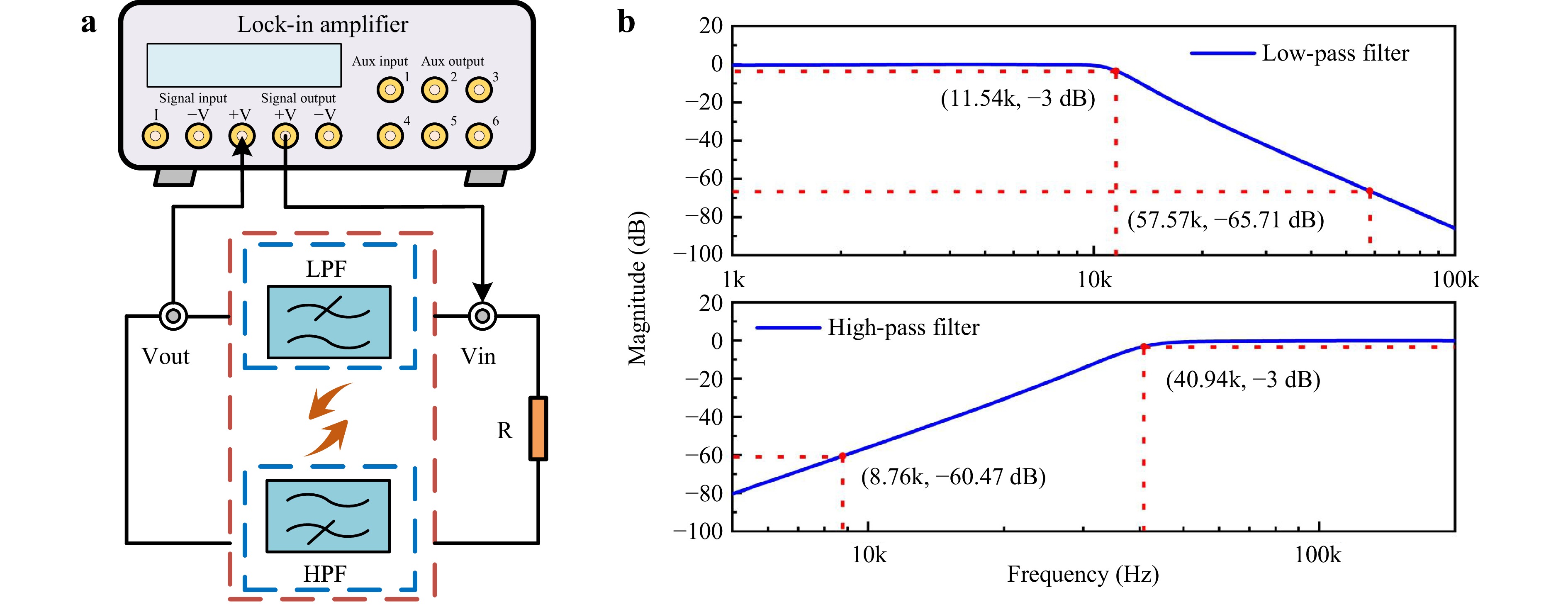
Fig. 5 Filter bandwidth characterization. a Measurement schematic of the filter magnitude-frequency characteristic. b Magnitude-frequency response of the LPF and HPF.
In LITES sensors, the laser wavelength modulation depth is a key parameter influencing the detection performance because it directly affects the strength of the gas absorption signal. To optimise this, we precisely adjusted the modulation depth applied to the CW-DFB lasers using a function generator. An LIA was then used to synchronously demodulate and record the amplitude of the second harmonic (2f) signal generated by the QTF at different modulation depths, as shown in Fig. 6a, b. The experimental results revealed that the 2f signal amplitudes in both channels initially increased and then decreased as the modulation depth increased. The peak amplitude of the CH4 channel was achieved at a modulation depth of 5.11 mA, whereas the best response for the C2H2 channel was obtained at 23.26 mA. The difference in the optimal modulation depths for the CH4 and C2H2 channels primarily resulted from the distinct electro-optic tuning efficiencies of the lasers used.
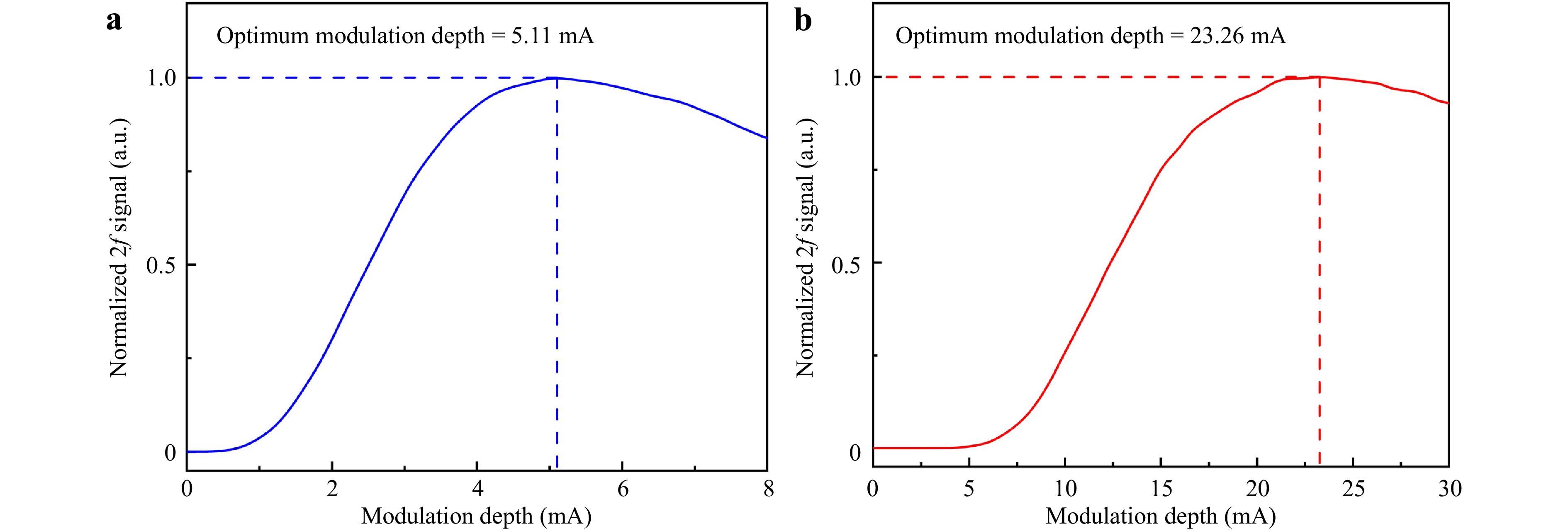
Fig. 6 Relationship between modulation depth and the 2f signal amplitude. a Fundamental (for CH4 detection). b First overtone (for C2H2 detection).
The channel crosstalk ratio (CTR) is a key indicator of the performance of dual-gas sensors. To precisely quantify the channel isolation capability of the sensor, we adopted the following measurement method: First, the gas cell was filled with 20,000 ppm CH4 (without C2H2), and the signal amplitudes of the CH4 channel (S11) and C2H2 channel (S12) were recorded. The gas cell was filled with 20,000 ppm of C2H2 (without CH4), and the signal amplitudes of the CH4 (S21) and C2H2 channels (S22) were recorded. The CTR was calculated as follows:
$$ \begin{cases} CT{R}_{12}=({S}_{12}/{S}_{11})\times 100{{\%}}\\ CT{R}_{21}=({S}_{21}/{S}_{22})\times 100{{\%}} \end{cases} $$ (6) The experimental measurements using the crosstalk ratio analysis are summarised in Table 1. The CTR from the CH4 channel to the C2H2 channel (CTR12) was 0.012%, whereas the crosstalk from the C2H2 channel to the CH4 channel (CTR21) was 0.057%, with an average CTR of 0.035%. This low CTR can be attributed to two main factors: first, the mechanical orthogonality between the fundamental and first overtone vibrational modes of the QTF, and second, the MHD method adopted by the sensor, which effectively achieves frequency-domain isolation. The results demonstrate that the sensor effectively avoids mutual interference during dual-gas measurements, thereby ensuring the accuracy of the detection results.
Excitation channel Detection channel Signal amplitude CTR CH4 CH4 550.91 mV 0.012% C2H2 63.74 μV C2H2 C2H2 34.04 mV 0.057% CH4 19.49 μV Table 1. CTR analysis of the DG-LITES sensor.
After confirming the absence of significant inter-channel interference in the DG-LITES sensor, we investigated the linear concentration responses of the CH4 and C2H2 channels in the sensor separately. A two-channel flow controller was used to blend the gases and generate different concentrations of CH4 and C2H2. In this experiment, the concentration ranges for CH4 and C2H2 were set from 2,500 to 20,000 ppm. The data for each concentration point were obtained from ten independent repeated measurements. The data acquisition duration was 20 s, with a sampling interval of 1 s, and the average over the stabilised period was taken as the measurement result for that point. A 2-min interval was maintained between two consecutive measurements to ensure a uniform and stable concentration inside the gas cell. As shown in Fig. 7a, b, the peak 2f signals for CH4 and C2H2 at different concentrations were fitted, both yielding a coefficient of determination (R2) of 0.999, thus demonstrating excellent linearity. The green error bars in Fig. 7a, b reflect the signal fluctuation range at each concentration point, further demonstrating good repeatability and measurement accuracy of the experimental data.
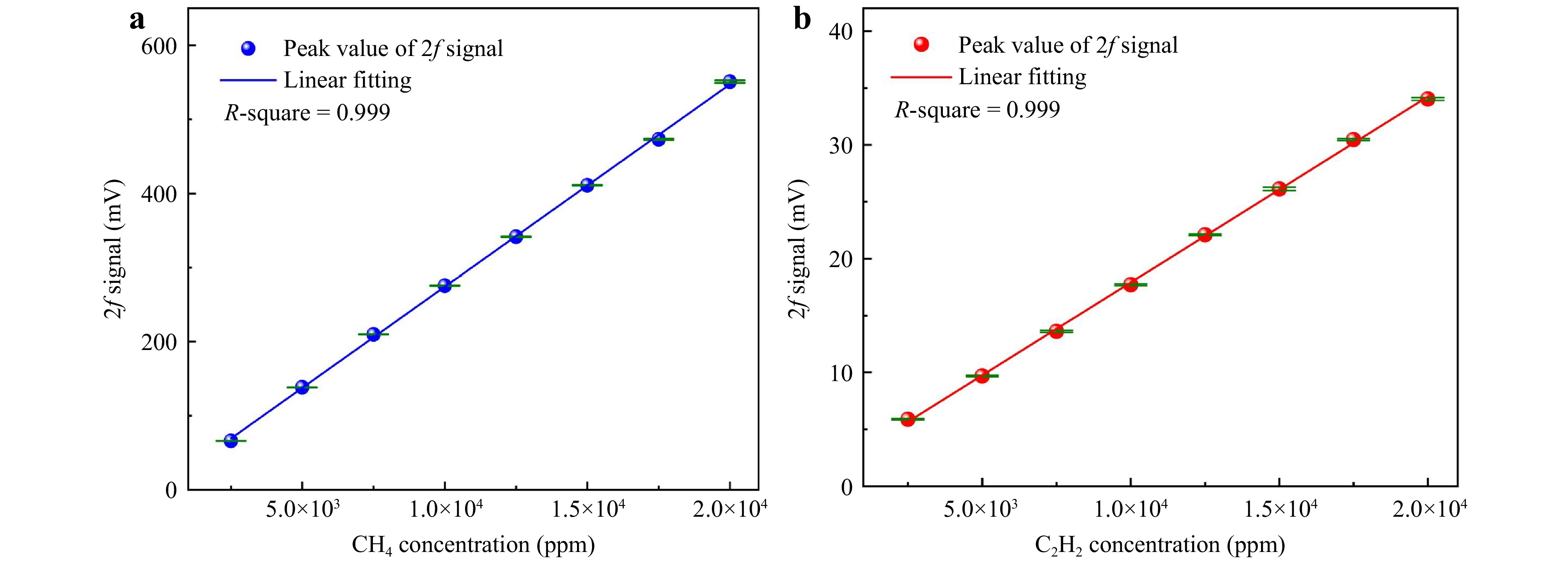
Fig. 7 Concentration response of the DG-LITES sensor. a Fitted linear relationship of the 2f signal peaks for the CH4 channel of the DG-LITES sensor. b Fitted linear relationship of the 2f signal peaks for the C2H2 channel of the DG-LITES sensor.
To evaluate the baseline noise characteristics of the sensor, we introduced pure N2 gas into the gas cell at a constant flow rate of 240 mL/min, and the sensor output signals were continuously recorded for 300 s, as shown in Fig. 8a, b. Statistical analysis of the signals revealed standard deviations (1σ) of 46.38 μV and 60.42 μV for the CH4 and C2H2 channels, respectively. Based on the measured data, the minimum detection limits (MDLs) for CH4 and C2H2 were calculated to be 1.68 and 35.5 ppm, respectively.
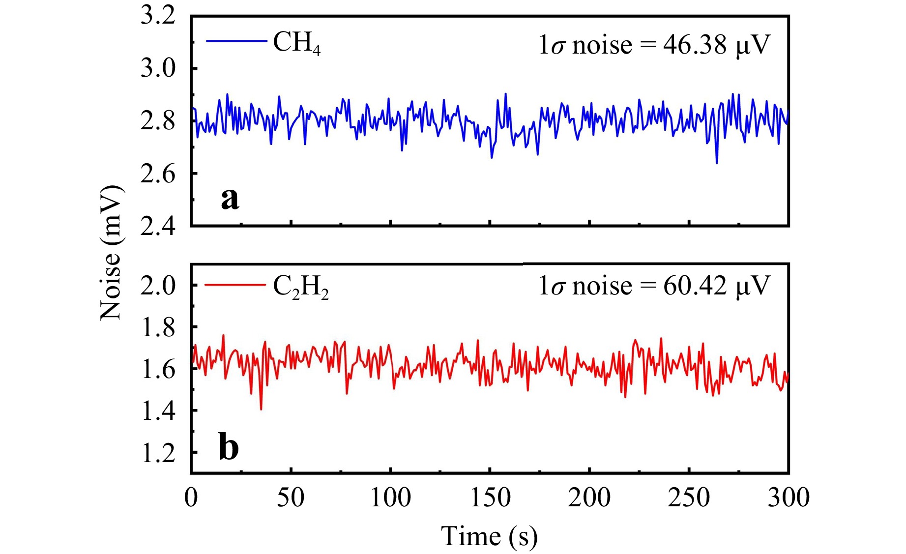
Fig. 8 Noise assessment under pure N2 background a CH4 channel. b C2H2 channel.
Comparative experimental tests were conducted to verify the technical advantages of MHD over the conventional direct FDM method. The traditional FDM method was implemented by directly connecting the amplified QTF signal to a dual-channel LIA with the reference frequency of one channel set to f0 (8,758.42 Hz) and that of the other set to f1 (57,556.74 Hz) for the detection of CH4 and C2H2, respectively. Both schemes employed the same self-designed amplifier for the initial signal amplification, whereas in the traditional FDM method, the input range of the LIA was independently optimised for each channel to achieve the best SNR. During the experiment, 20,000 ppm of CH4 and 20,000 ppm of C2H2 were successively introduced into the gas cell, and the corresponding signal amplitudes and crosstalk values were recorded. Subsequently, pure N2 was introduced to record the sensor noise. The performance comparison data for the two methods are listed in Table 2.
Method Average CTR Channel Signal amplitude Noise SNR Traditional
FDM method0.068% CH4 56.37 mV 15.43 μV 3706.11 C2H2 3.63 mV 21.36 μV 169.94 This work 0.035% CH4 550.91 mV 46.38 μV 11878.18 C2H2 34.04 mV 60.42 μV 563.39 Table 2. Comparison with the traditional FDM method measurement.
The experiment showed that the average CTR of the MHD scheme was 0.035%, which is superior to that of the traditional direct FDM method (0.068%). Note that the mixer in the MHD scheme introduces an approximate 10-fold gain, resulting in signal amplitudes of 550.91 mV for the CH4 channel and 34.04 mV for the C2H2 channel, higher than those of the traditional scheme (56.37 and 3.63 mV, respectively). Although the noise of the MHD scheme also increased, its SNRs reach 11,878.18 for the CH4 channel and 563.39 for the C2H2 channel, which were significantly better than those of the traditional scheme.
After determining that the MHD method features a lower channel crosstalk and a higher SNR, we conducted a quantitative analysis of its measurement accuracy and repeatability. In this analysis, the maximum linearity error (eL) was the critical metric for evaluating the maximum deviation between the measured values and ideal fitted line across the full measurement range of a sensor. It is expressed as follows:
$$ {e}_{\rm L}=\frac{{\Delta }_{\max }}{{C}_{\rm U}-{C}_{\rm L}}\times 100\mathrm{\% } $$ (7) where Δmax is the maximum deviation between the actual measured and predicted values. CU and CL denote the maximum and minimum concentrations within the test range of the sensor, respectively.
In this experiment, based on the concentration response data of CH4 and C2H2 within the 2,500–20,000 ppm range, the maximum deviation between the sensor output and least-squares fitted line was calculated. As shown in Fig. 9, the maximum linearity errors of the DG-LITES sensor were determined to be 1.39% full-scale span (FSS) for the CH4 channel and 1.48% FSS for the C2H2 channel. These results indicated that the DG-LITES sensor exhibits well-defined linearity over its entire operating range, satisfying the accuracy requirements for most industrial applications.
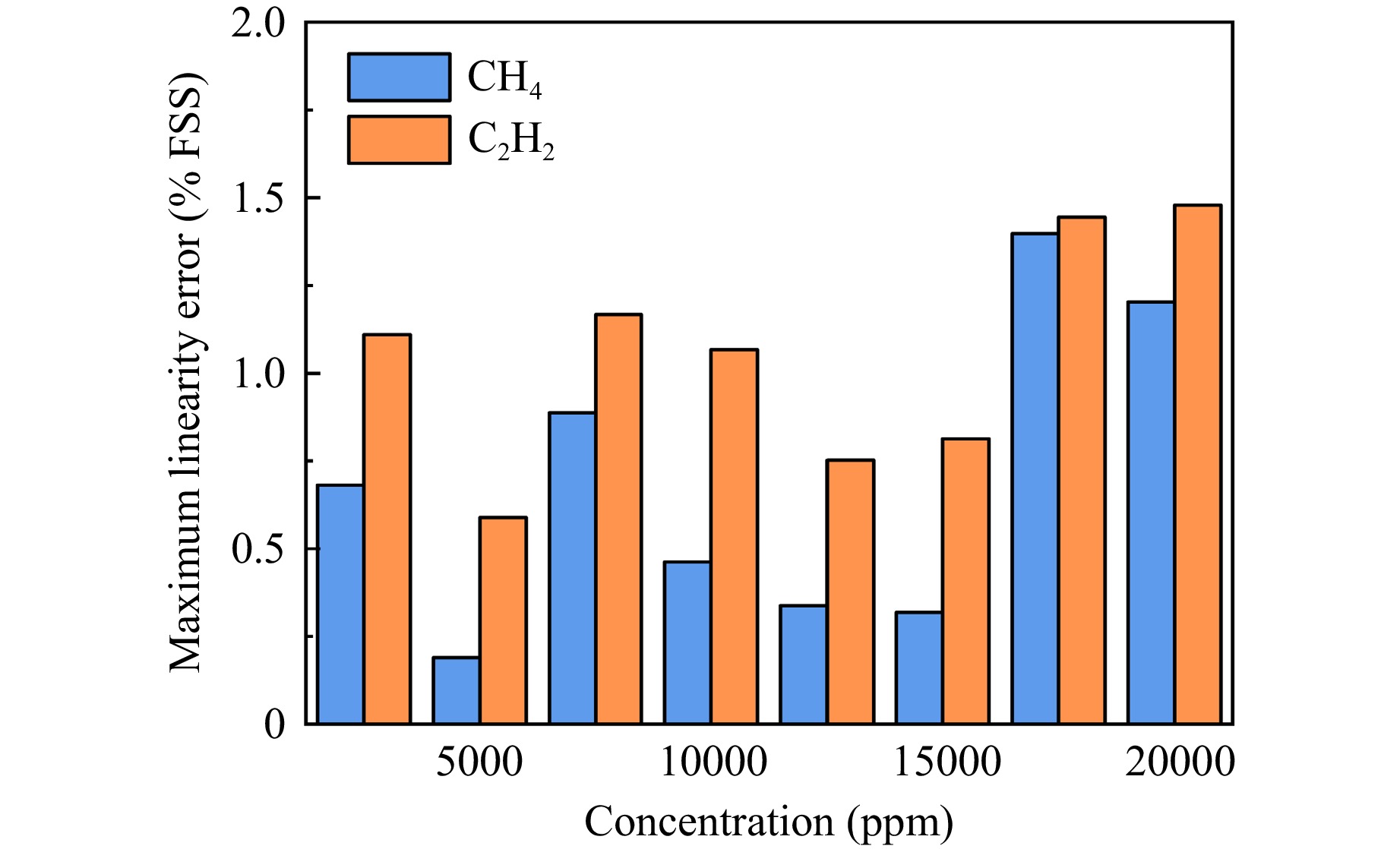
Fig. 9 Maximum linearity error of the DG-LITES sensor.
To comprehensively evaluate the measurement accuracy and reliability of the DG-LITES sensor, we conducted a systematic analysis focusing on two key metrics: the relative systematic error (eS) and maximum relative error (eR). Repeated measurements were performed using standard gases at different concentrations, and the relative deviations between the measured average values and standard reference values were calculated to quantify the accuracy of the sensor. eS is expressed as follows:
$$ {e}_{\rm S}=\frac{\left| {C}_{\rm AVE}-{C}_{\rm X,a}\right| }{{C}_{\rm X,a}}\times 100\mathrm{\% } $$ (8) where CAVE is the average of the actual measurements, and CX,a is the reference true value calibrated by the gas flow controller.
The relative systematic error is illustrated in Fig. 10a. The experimental results indicated that across the eight tested concentration points, the eS of the CH4 channel ranged from 0.2% to 2%, with an average of 0.95%, whereas that of the C2H2 channel ranged from 0.2% to 1.9%, with an average of 0.93%. Furthermore, the eR of the sensor was quantified through statistical analysis of all data points across the full measurement range. eR is defined as the maximum absolute value of the relative deviations between all individual measured values and the standard reference values across the entire measurement range. The formula is expressed as follows:
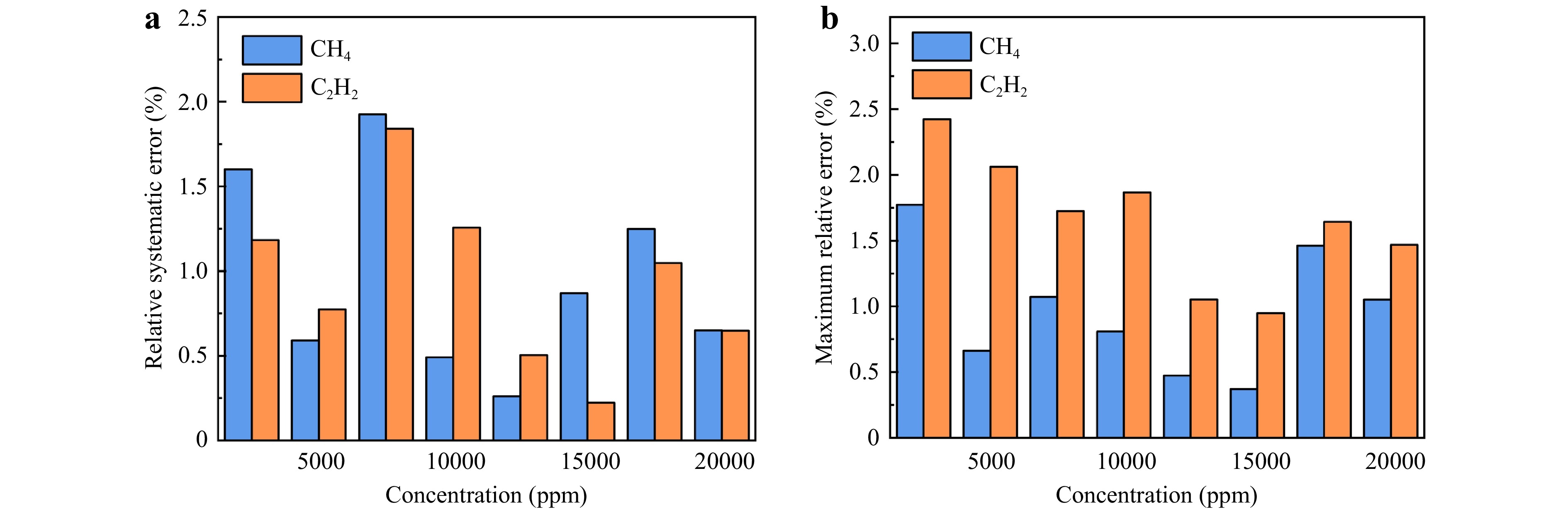
Fig. 10 Relative systematic and maximum relative errors of the DG-LITES sensor a Relative systematic error. b Maximum relative error.
$$ {e}_{\rm R}={\rm{Max}}\left(\frac{\left| {C}_{\rm X}(i)-{C}_{\rm X,a}\right| }{{C}_{\rm X,a}}\times 100\mathrm{\% }\right).\;i=\left\{1,2,\ldots ,10\right\} $$ (9) where Cx(i) represents each actual measurement.
The maximum relative error is illustrated in Fig. 10b. The analysis results indicated that the eR values for the CH4 and C2H2 channels were 1.8% and less than 2.5%, respectively. This error analysis not only confirmed that the DG-LITES sensor possesses good measurement accuracy and reliability but also provides important insights for calibration strategies and safety margin design in practical applications.
To further evaluate the long-term stability of the DG-LITES sensor, we performed an Allan deviation analysis for both the CH4 and C2H2 channels. Fig. 11a, b present the Allan deviation plots for the CH4 and C2H2 channels, respectively; both exhibited a characteristic V-shaped trend. In the initial phase, the Allan deviation for both channels decreased rapidly with increasing average time, indicating that white noise dominated this region. As the average time increased, the Allan deviation for both channels began to increase, suggesting the influence of long-term drift effects on the sensor. When the average time of the DG-LITES sensor was set to 300 s, the MDLs for the CH4 and C2H2 channels were optimised to 0.13 ppm and 2.93 ppm, with normalised noise-equivalent absorption (NNEA) coefficients of 2.73 × 10⁻⁹ and 9.61 × 10⁻⁸ cm−1·W·Hz−1/2, respectively.
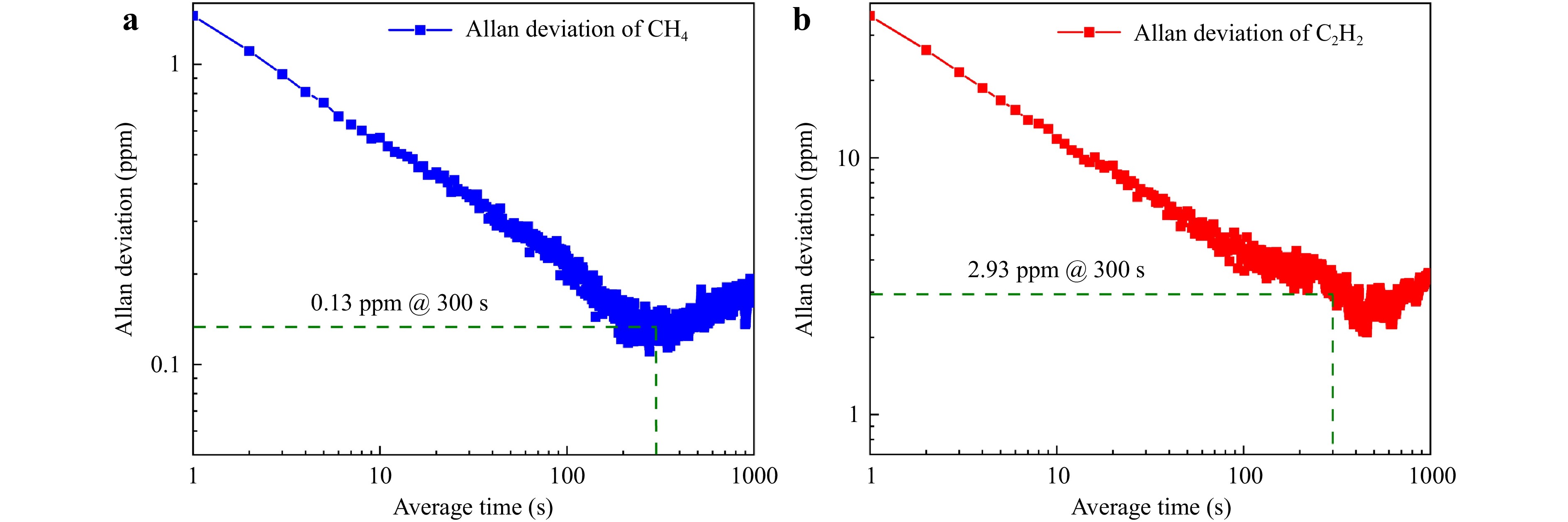
Fig. 11 Allan deviation of the DG-LITES sensor a CH4 channel. b C2H2 channel.
To highlight the technical advantages of the DG-LITES sensor developed in this study, we conducted a comprehensive comparison with recently reported advanced multigas-sensing techniques based on photoacoustic spectroscopy (PAS) and QEPAS, as summarised in Table 3. Note that while some studies have achieved multicomponent detection based on FDM22,26, they require multiple photoacoustic cells (PACs) and cantilever-based fibre-optic acoustic sensors (CFOAS) or microphones (Mics), resulting in relatively complex sensor systems. Furthermore, a TDM approach has also been reported38, and this method cannot achieve truly simultaneous measurements. In contrast, the DG-LITES sensor utilises only one gas cell, one QTF, and one LIA to achieve the true simultaneous detection of two gas species while maintaining high sensitivity.
Technology Method Gas type Resource equipment Real-time? NNEA PAS26 FDM CH4
C2H2Two PACs,
One CFOAS,
Two LIAsY 6.65 × 10⁻⁹ cm−1·W·Hz−1/2
9.71 × 10⁻⁹ cm−1·W·Hz−1/2PAS22 FDM C2H2
CH4
CO2One PACs,
Three Mics,
Three LIAsY 4.21 × 10⁻⁸ cm−1·W·Hz−1/2
1.69 × 10⁻⁷ cm−1·W·Hz−1/2
5.43 × 10⁻⁷ cm−1·W·Hz−1/2QEPAS38 TDM CH4
C2H2One cell,
One QTF,
One LIAN 7.24 × 10⁻⁸ cm−1·W·Hz−1/2
3.73 × 10⁻⁸ cm−1·W·Hz−1/2This paper MHD CH4
C2H2One cell,
One QTF,
One LIAY 2.73 × 10⁻⁹ cm−1·W·Hz−1/2
9.61 × 10⁻⁸ cm−1·W·Hz−1/2Table 3. Performance comparison of different detection techniques.
Although the current system only achieves partial simplification, it holds considerable integration potential for the future. It can be replaced by a single multichannel waveform generation chip, and the functionality of the LIA can also be integrated into a dedicated chip equipped with a digital demodulation core. Most importantly, the MHD architecture simplifies the complex multi-frequency signal processing into operations at a single intermediate frequency. This significantly reduces the design difficulty and resource requirements for subsequent digital integrated circuits, thereby laying a solid foundation for developing miniaturised multigas-sensing modules.
-
In this paper, a novel DG-LITES sensor-based MHD method is presented. The core value of the DG-LITES sensor lies in its innovative integration of frequency multiplexing with the MHD method, which fundamentally simplifies a part of the system hardware. Using only a single QTF sensing element and one demodulation instrument, it establishes a dual-channel detection system with inter-channel crosstalk suppressed below 0.057%. Experimental results demonstrated that the DG-LITES sensor exhibits an excellent linear response for both CH4 and C2H2 (R2 > 0.999), with maximum nonlinear errors as low as 1.39% and 1.48% FSS, respectively. The average relative systematic errors were 0.95% and 0.93% with maximum relative errors of 1.8% and 2.5%, respectively. Allan deviation analysis confirmed the outstanding long-term stability of both CH4 and C2H2 channels. At an optimal average time of 300 s, the MDLs are further optimised to 0.13 and 2.93 ppm, with NNEA coefficients of 2.73 × 10⁻⁹ and 9.61 × 10⁻⁸ cm−1·W·Hz−1/2, respectively. Although discrete filters and mixers are used in this proof-of-concept setup, the MHD architecture fundamentally simplifies the signal processing by unifying all channels to a single intermediate frequency, which is highly advantageous for future chip-level integration. The essential simplification of this scheme, which employs a single LIA, lies in transforming the reliance of dual-channel demodulation on multiple high-frequency reference sources into dependence on a single intermediate-frequency reference using the MHD technique. This significantly reduces the complexity of system synchronisation and enhances the compatibility with future dedicated integrated demodulation circuits. Furthermore, the proposed sensing paradigm exhibits high versatility and scalability. By incorporating lasers at different wavelengths and utilising other higher-order vibrational modes of the QTF, this scheme can be readily extended to the simultaneous detection of additional gas species.
-
We are grateful for the financial support from the National Natural Science Foundation of China (Grant Nos. 62335006, 62275065, 62505066, 62022032, and 62405078), the Heilongjiang Postdoctoral Fund (Grant No. LBH-Z23144 and LBH-Z24155), the Natural Science Foundation of Heilongjiang Province (Grant No. LH2024F031), China Postdoctoral Science Foundation (Grant No. 2024M764172), and Open Subject of Hebei Key Laboratory of Advanced Laser Technology and Equipment (HBKL-ALTE2025001).
Dual-gas light-induced thermoelastic spectroscopy sensor based on mixed-frequency heterodyne demodulation
- Light: Advanced Manufacturing , Article number: 54 (2026)
- Received: 09 December 2025
- Revised: 02 April 2026
- Accepted: 02 April 2026 Published online: 13 May 2026
doi: https://doi.org/10.37188/lam.2026.054
Abstract: A novel dual-gas light-induced thermoelastic spectroscopy (DG-LITES) sensor based on mixed-frequency heterodyne demodulation (MHD) is reported. The DG-LITES sensor exploits the fundamental and first overtone vibration modes of a single self-designed low-frequency quartz tuning fork to achieve the high-performance simultaneous detection of methane (CH4) and acetylene (C2H2). Using a frequency-division multiplexing mechanism, this technique creates dual detection channels based on a single sensing element. Furthermore, it uses the MHD method to convert photothermal signals at different frequencies into a unified intermediate frequency, thereby enabling synchronous demodulation with only one correlation demodulation unit. The DG-LITES sensor not only maintains system compactness but also effectively suppresses inter-channel crosstalk below 0.057%. Experimental results demonstrated that the DG-LITES sensor exhibited excellent linear responses to both CH4 and C2H2 (R2 > 0.999), with maximum nonlinearity errors as low as 1.39% and 1.48% full-scale span, respectively. The mean relative systematic errors were 0.95% and 0.93%, respectively, whereas the maximum relative errors were 1.8% and 2.5%, respectively. Allan deviation analysis validated the excellent long-term operational stability of both the CH4 and C2H2 channels. The minimum detection limits for both channels were 0.13 and 2.93 ppm, with normalised noise-equivalent absorption coefficients of 2.73 × 10⁻⁹ and 9.61 × 10⁻⁸ cm−1·W·Hz−1/2, respectively. This paper presents a universal sensing architecture that offers a novel solution to the long-standing trade-off between performance and system complexity in multi-gas detection.
Research Summary
Dual-gas light-induced thermoelastic spectroscopy sensor based on mixed-frequency heterodyne demodulation
Researchers have developed a dual-gas light-induced thermoelastic spectroscopy sensor that enables simultaneous detection of methane and acetylene using a single quartz tuning fork. By exploiting the fundamental and first overtone vibration modes of the tuning fork and employing a mixed-frequency heterodyne demodulation method, the system converts photothermal signals at different frequencies into a unified intermediate frequency, allowing synchronous demodulation with only one lock-in amplifier. This approach suppresses inter-channel crosstalk below 0.057% and simplifies system architecture. The sensor demonstrates excellent linear response, low nonlinearity errors, and minimum detection limits of 0.13 ppm for methane and 2.93 ppm for acetylene, offering a compact and high-performance solution for multi-gas detection.
Rights and permissions
Open Access This article is licensed under a Creative Commons Attribution 4.0 International License, which permits use, sharing, adaptation, distribution and reproduction in any medium or format, as long as you give appropriate credit to the original author(s) and the source, provide a link to the Creative Commons license, and indicate if changes were made. The images or other third party material in this article are included in the article′s Creative Commons license, unless indicated otherwise in a credit line to the material. If material is not included in the article′s Creative Commons license and your intended use is not permitted by statutory regulation or exceeds the permitted use, you will need to obtain permission directly from the copyright holder. To view a copy of this license, visit http://creativecommons.org/licenses/by/4.0/.

 DownLoad: