





-
Metasurfaces are two-dimensional planar artificial structures composed of a series of subwavelength microstructures1. By designing the geometric shape, size, and spatial arrangement of these microstructures, it is possible to control the phase, amplitude, and polarisation of electromagnetic waves, thereby achieving powerful wavefront control capabilities. In particular, in the terahertz (THz) frequency regime (0.1–10 THz)2, conventional optical components suffer from large footprints and limited functionality due to the scarcity of suitable natural materials3. Metasurfaces have brought transformative advances4–6. They not only significantly reduce the size and weight of THz devices but also expand the toolbox of wavefront control, enabling novel applications such as THz vector and vortex beam generation7–9, polarisation conversion10, beam steering11,12, and three-dimensional holography13.
However, the majority of existing THz metasurfaces are static in nature as their operational characteristics are fixed once fabricated. This inherent limitation severely restricts their adaptability in dynamic scenarios, particularly in emerging fields such as THz wireless communications14, real-time imaging, and intelligent sensing systems15,16, where dynamic control of beams is crucial. Therefore, the realisation of dynamic and tuneable metasurfaces has become a core goal in modern THz photonics research. To address this challenge, various active tuning strategies have been explored, including thermal17–19, electrical20,21, optical22–25, and mechanical25–27 modulation. Among these approaches, mechanical strain tuning, particularly through the stretching of flexible substrates, has attracted increasing attention due to its continuous tunability, excellent reversibility, high stability, and compatibility with wearable electronic products. In 2023, Zhuang et al. proposed an active THz wavefront modulator composed of a C-shaped split-ring phase gradient array and liquid crystal elastomer substrate, which enables the THz beam steering by adjusting the deflection of the liquid crystal elastomer substrate27. In 2025, Shao et al. proposed a stretchable THz metasurface lens, which consists of a silver paste rod array and silicone substrate28. However, when the metasurface lens was stretched to 1.15 times of its original size, the silver paste rod broke and its control capability deteriorated. Conventional metallic or semiconductor-based metasurfaces often suffer from performance degradation under repeated deformation, such as cracking, delamination, or loss of conductivity, which hinders their long-term reliability in stretchable device architectures.
As one of the most promising nanomaterials, carbon nanotubes (CNTs)28–32 exhibit an exceptional mechanical strength, high electrical conductivity, excellent thermal stability, and intrinsic elasticity, making them ideal candidates for flexible and stretchable optoelectronic devices. Recently, Katyba et al. demonstrated a stretchable THz zone plate composed of concentric rings fabricated from a single-walled carbon nanotube (SWCNT) film, integrated with a stretchable polymer substrate, achieving a tuneability of 50% in focal length through mechanical stretching33. However, this previous study, demonstrating the feasibility of SWCNTs for stretchable THz devices, utilised them only for amplitude control, leaving their potential for phase modulation largely untapped.
In this paper, we propose and demonstrate a design scheme for stretchable SWCNT-based metasurfaces that enable dynamic control of the THz wavefront through mechanical deformation, as shown in Fig. 1. Based on the Pancharatnam-Berry (PB) phase, the phase modulation units in the metasurface are a series of SWCNT rods prepared on a silicone substrate, which are carefully arranged to achieve wavefront manipulation. Two types of tuneable THz metasurface devices are designed and demonstrated, a focus-tuneable metasurface lens and off-axis metasurface lens capable of dynamic beam steering. With the stretching of the metasurfaces, continuous focus movement and beam deflection are successfully observed in the experiment. By changing the amount of tensile deformation, the deflection angle of the beam can be precisely controlled. The SWCNT-based metasurface exhibits an excellent reliability, as its performance remains stable even after repeated stretching tests.
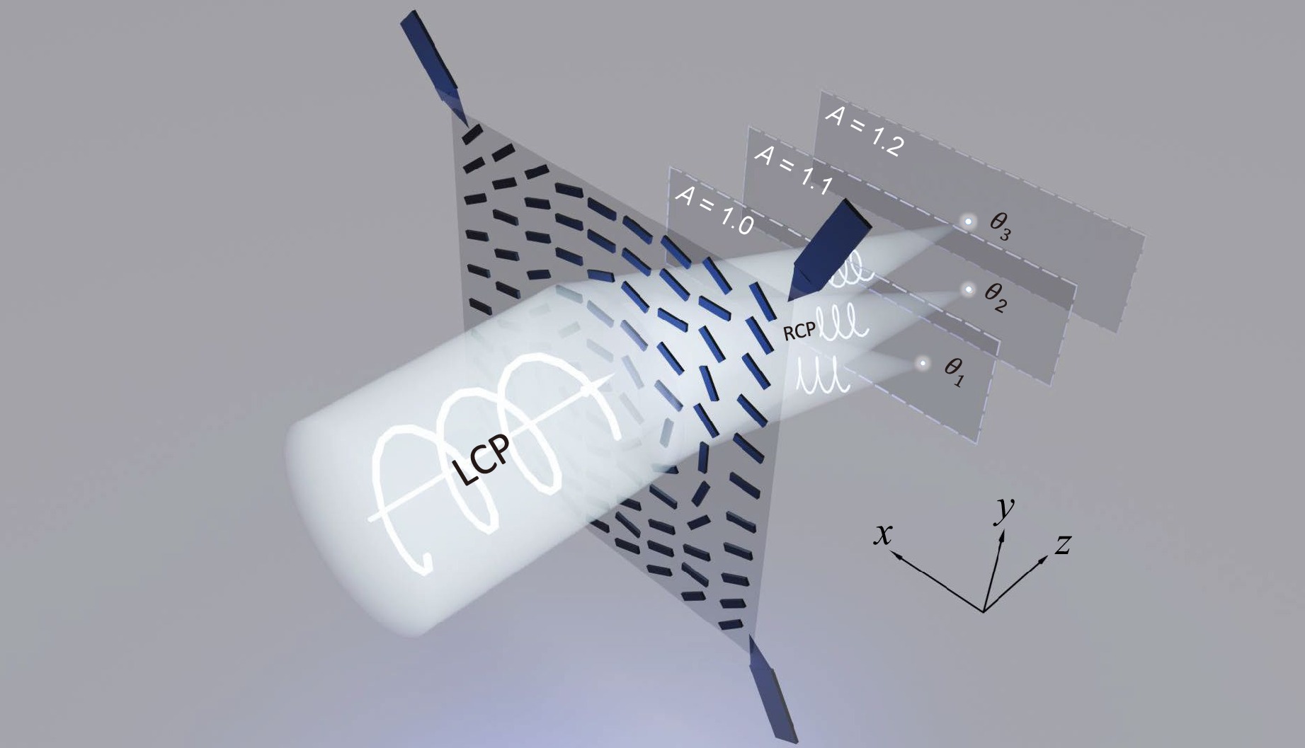
Fig. 1 Schematic of a SWCNT-based metasurface for wavefront manipulation via tensile deformation (LCP: terahertz wave component with left circular polarisation; RCP: transmitted THz wave with right circular polarisation; A denote different stretch factors).
-
The stretchable SWCNT-based metasurface consists of ~200 nm-thick SWCNT rods with various orientation angles on a 200 μm-thick silicone substrate, as shown in Fig. 1. Each SWCNT rod serves as a phase-tuning unit, operating on the PB phase principle34. When a left/right circularly polarised (LCP/RCP) THz wave is normally incident on a SWCNT rod with an orientation angle of θ, the transmitted right/left circularly polarised (RCP/LCP) component exhibits a phase shift of ±2θ 35. Considering the optical properties of the silicone substrate and SWCNT film, full-wave electromagnetic simulations are employed to optimise the parameters of each SWCNT-based metasurface unit. Eight rods with distinct orientation angles of 0°, 19°, 37°, 60°, 90°, 109°, 127°, and 150° are selected as fundamental phase-tuning elements operating at 0.35 THz, providing a full 0–2π phase coverage with a step of π/4. The electromagnetic modulation characteristics of the metasurface units constitute the foundation to realise dynamic wavefront modulation metasurfaces through tensile deformation. Further electromagnetic simulations confirm that, under an applied stretching deformation, each selected metasurface unit maintains stable amplitude and phase responses for the scattered RCP component (for further details, see Note 1 of Supplementary Information). Therefore, the tuneable performance of the metasurface device originates from the geometric rescaling of the spatial phase profile induced by mechanical stretching.
-
In the Cartesian coordinate system, the spatial phase profile of an ideal lens with a focal length f is governed by the equation36
$$ \varphi \left(x,y\right)=\frac{2{\text{π}} }{\lambda }\left(f-\sqrt{{\left(x-{x}_{0}\right)}^{2}+{\left(y-{y}_{0}\right)}^{2}+{f}^{2}}\right) $$ (1) where λ denotes the operating wavelength of the lens, f is the focal length, and (x0, y0) represent the coordinates of the focal spot on the focal plane. A metasurface lens with a focal length of 20 mm with an on-axis focus is designed. The entire sample is an array composed of 60 × 60 unit cells. The spatial phase profile is derived from Eq. 1 and quantised in π/4 increments across the range of 0 to 2π. The quantised phase profile, illustrated in Fig. 2a, is then used to assign the corresponding phase-tuning unit cells for device fabrication. The fabricated metasurface lens has a total area of 21 mm × 21 mm. A photograph of the device is shown in Fig. 2b, with a magnified optical microscopy image of the sample provided in the inset. To investigate the evolution of the optical field under mechanical deformation, the metasurface lens is uniformly stretched using a custom-built stretching holder, as shown in Fig. 2c. We define the stretch factor as A, indicating that the side length l of the entire sample is scaled by a factor of A. For stretch factors A = 1.0, 1.1 and 1.2, the corresponding side lengths of the metasurface sample are 21.0, 23.1 and 25.2 mm, respectively. The structural response of adjacent SWCNT rods under both stretched and released conditions is presented in Fig. 2d.
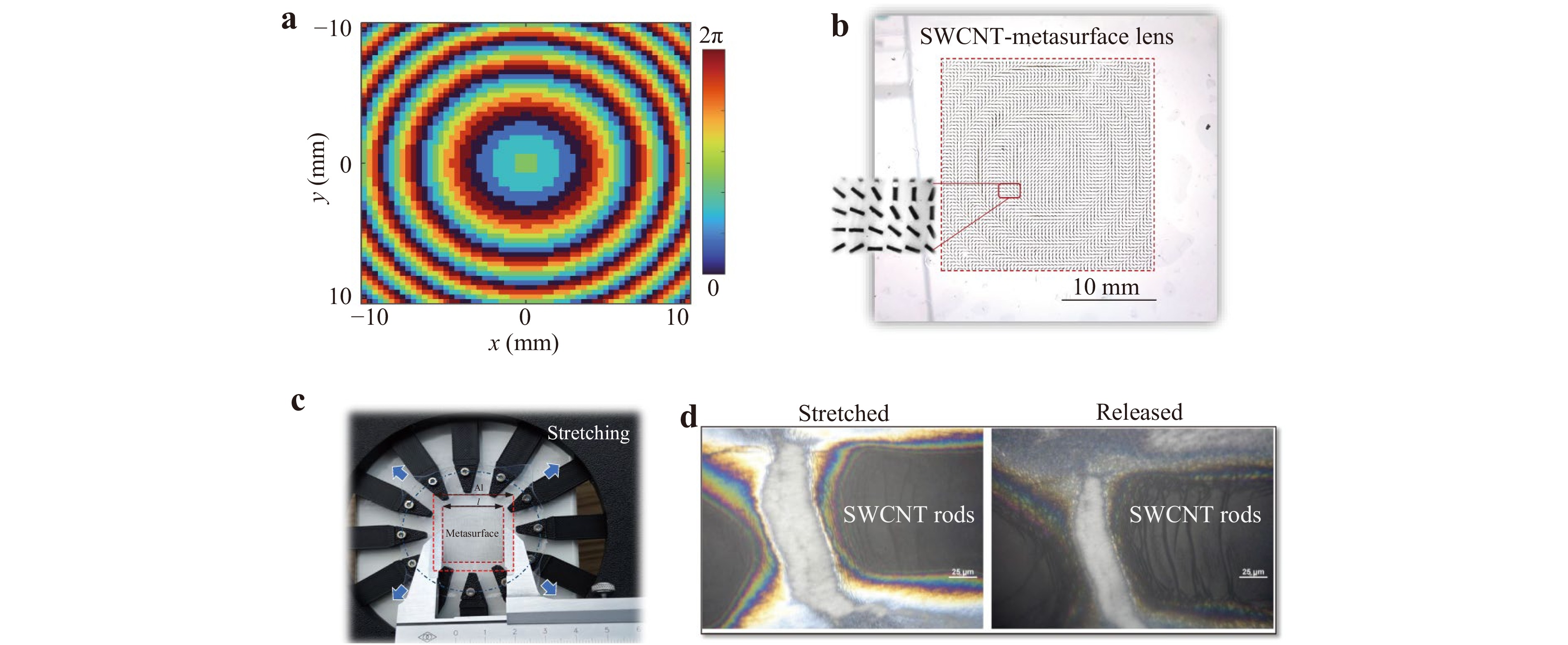
Fig. 2 Metasurface lens design and fabrication. a Quantised phase profile for a focal length of f = 20 mm at 0.35 THz. b Photograph of the fabricated SWCNT-based metasurface lens, with a magnified optical micrograph shown in the inset. c Sample mounted in the custom-built stretching holder. d Structural comparison of adjacent SWCNT rods in the stretched and recovered state.
The transmitted THz optical field distribution after the metasurface sample is characterised using a THz polarisation holographic imaging system37,38. In the experiment, an LCP THz wave was normally incident along the z-axis onto the metasurface lens placed in the xy plane. A ZnTe crystal positioned 11.5 mm behind the sample directly measured the complex field distribution $ {U}_{\rm{RCP}}({x}_{0},{y}_{0}) $ of the transmitted RCP wave. The field distribution on successive xy planes behind the detection plane, spaced at intervals of 0.02 mm, was then computed using the Huygens–Fresnel diffraction integral39:
$$ {U}_{\rm{RCP}}\left(x,y,{\textit z}\right)=\frac{{\textit z}}{j\lambda }\iint {U}_{\rm{RCP}}\left({x}_{0},{y}_{0}\right)\frac{\mathrm{exp} (jkr)}{{r}^{2}}\mathrm{d}{x}_{0}\mathrm{d}{y}_{0} $$ (2) where
$$ r=\sqrt{{(x-{{x}_{0}})}^{2}+{(x-{{y}_{0}})}^{2}+{{\textit z}}^{2}} $$ (3) and k = 2π/λ is the corresponding free-space wavenumber.
In this study, a maximum stretch factor of A = 1.2 is employed. This limit is imposed by two critical factors. First, for the 200 μm-thick silicone substrate, higher stretch factors risk substrate damage. Second, at A = 1.2, the metasurface sample expands to dimensions of 25.2 mm × 25.2 mm, which exceeds the diameter of the incident THz beam spot (20 mm). Further stretching would leave more of the sample uncovered by the THz beam, resulting in an insufficient modulation and inaccurate measurements. Fig. 3a shows the propagation evolution of the transmitted 0.35 THz RCP wave under different stretching states. The corresponding intensity distributions at the focal plane are presented in Fig. 3b. As observed, in the unstretched state (A = 1.0), the RCP wave is focused at 19.4 mm from the sample. The mechanical stretching induces a continuous axial shift of the focal spot away from the metasurface lens. At stretch factors of 1.1 and 1.2, the focus moves to 24.6 and 28.2 mm, corresponding to backward displacements of 5.2 and 8.8 mm relative to the unstretched case, respectively. Theoretically, mechanical stretching induces a geometric coordinate transformation (x, y) → (Ax, Ay), thereby rescaling the spatial phase distribution. For a coaxial metasurface lens with an initial focal length of f, the stretched lens exhibits a modified focal length governed by f′ = A2f (full theoretical derivations are presented in Note 2 of Supporting Information). Based on this relation, the theoretical focal length is estimated to be 24.2 and 28.8 mm when the stretch factor A is 1.1 and 1.2, respectively. Notably, the above analytical derivation relies on the Fresnel (paraxial) approximation. Considering our sample size (21 mm × 21 mm) and focal length (20 mm), the paraxial condition is not strictly satisfied, which may introduce minor discrepancies in the theoretical predictions. In contrast, simulations based on the Huygens-Fresnel diffraction integral provide more accurate and reliable results.
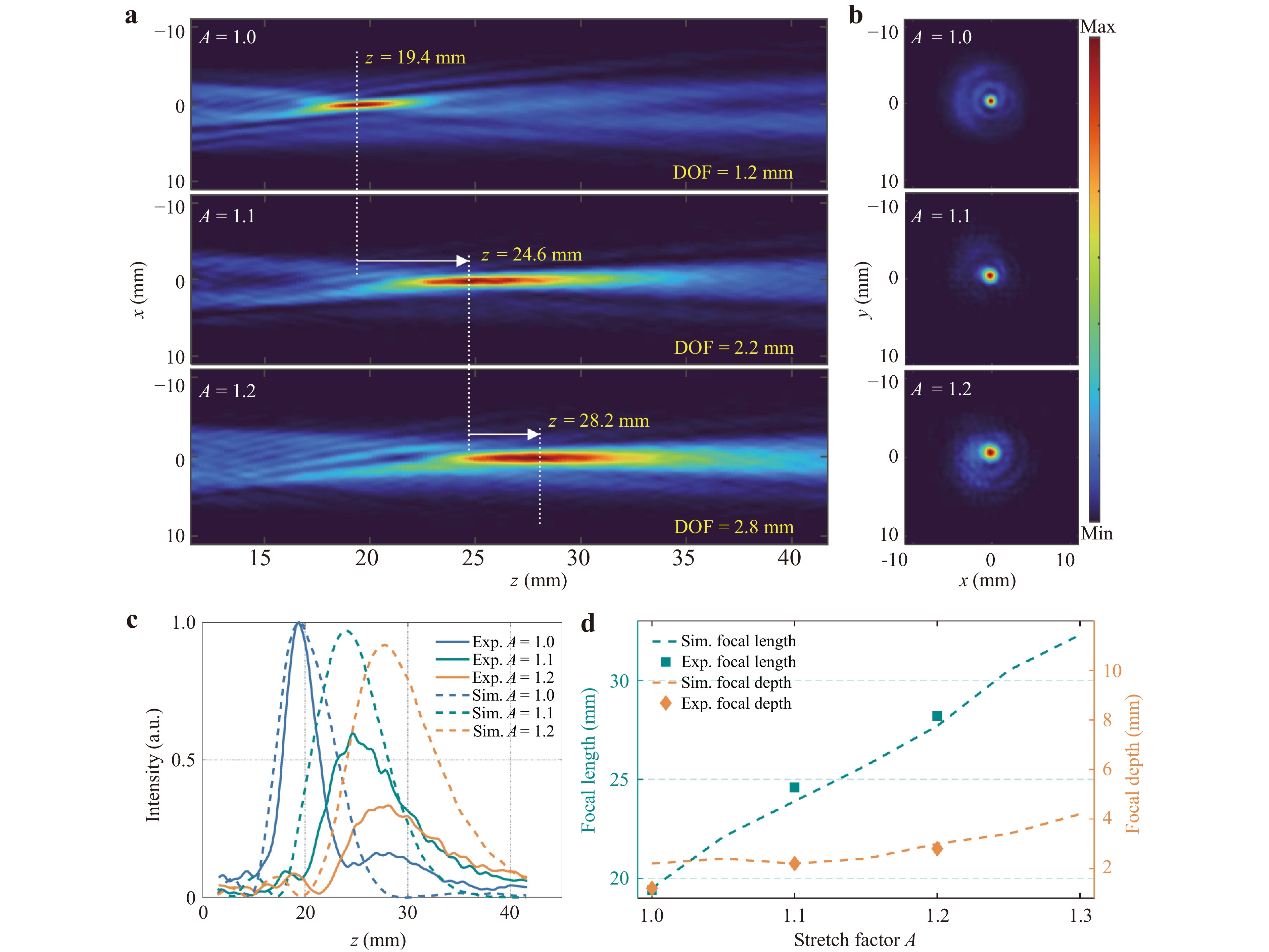
Fig. 3 Measured intensity distributions of the transmitted 0.35 THz RCP component through the metasurface lens under different stretch factors (A = 1.0, 1.1, 1.2). a Intensity distributions in the propagation (xz) plane. b Intensity distributions in each focal (xy) plane. c Axial intensity profiles of the focal spot along the z-direction, comparing experimental and simulated results. All data are normalised to the respective maximum focal intensity at the unstretched state (A = 1.0) for each dataset. d Dependences of the focal length and depth of focus on the stretch factor.
To validate the experimental results, numerical simulations to investigate the propagation evolution of the wavefront after modulation by the designed metasurface lens were performed (see Note 3 in Supplementary Information for simulation details). Fig. 3c compares the axial intensity profile extracted along the line x = 0 mm in Fig. 3a to the simulated axial intensity distribution. All data are normalised to the respective maximum focal intensity at the unstretched state (A = 1.0) for each dataset. In this figure, solid lines denote the measured values, dashed lines represent the simulated values, and the blue, cyan, and orange curves correspond to the axial intensity distributions at stretch factors of 1.0, 1.1 and 1.2, respectively. The focal positions exhibit an excellent agreement between the experiment and simulation across all stretching states. Noticeable deviations are observed in the absolute focal intensities, where the experimental values are consistently lower than the simulated predictions when the sample was stretched. This intensity discrepancy is primarily attributed to the intrinsic gap between idealised simulation models and realistic experimental conditions, arising from fabrication-induced scattering losses (e.g., surface roughness and dimensional deviations), unmodeled material absorption, and optical collection inefficiencies in the experimental setup. The dependences of the focal length and depth of focus (DOF) on the stretching deformation are summarised in Fig. 3d, where the DOF is defined as the axial range within which the optical intensity remains above 90% of the maximum value. Simulation results indicate that the unstretched metasurface focuses the RCP THz wave at a distance of 19.5 mm from the sample. Under stretch factors of 1.1 and 1.2, the focal positions shift to 23.9 and 27.7 mm, representing backward displacements of 4.4 and 8.2 mm relative to the unstretched case, respectively. The experimentally observed focal shift is slightly larger than the simulated value, which is likely due to deviations in the actual stretching amount during the experiment. In Fig. 3d, both simulation and experiment reveal a consistent trend of increasing DOF at larger stretch factors. For the stretch factors of 1.0, 1.1 and 1.2, the simulated DOF values are 2.2, 2.2 and 3.0 mm, while the experimental measurements yield 1.2, 2.2 and 2.8 mm for the same conditions, respectively. To facilitate the comparison of changes in lens performance, the key performance metrics are summarised in Table 1.
Stretch factor Method Focal length f (mm) DOF (mm) A = 1.0 Numerical simulation 19.5 2.2 Experimental 19.4 1.2 A = 1.1 Numerical simulation 23.9 2.2 Experimental 24.6 2.2 A = 1.2 Numerical simulation 27.7 3.0 Experimental 28.2 2.8 Table 1. Comparison of focal lengths and DOFs for different stretch factors.
-
We further demonstrate an off-axis focusing metasurface lens based on SWCNT, which enables dynamic beam steering through mechanical stretching. For an off-axis metasurface lens with a focal length of f and transverse deflection angle θ (measured from the optical axis along the x-axis), the target focal position is expressed as (f, θ). According to Eq. 1, its spatial phase distribution is expressed by36
$$ \varphi (x,y)=\frac{2{\text{π}} }{\lambda }(f-\sqrt{{\left(x-f\cdot \tan \theta \right)}^{2}+{y}^{2}+{f}^{2}}) $$ (4) Fig. 4a presents the quantised spatial phase profile of an off-axis metasurface lens with a focal length of 20 mm and beam steering angle of 20° at 0.35 THz. Based on this phase distribution, a SWCNT-based off-axis metasurface lens is fabricated. A photograph of the fabricated sample is presented in Fig. 4b. In the experiment, the detection crystal was positioned 13 mm directly behind the sample. Using the THz polarisation holographic imaging system, the complex field distributions of the transmitted RCP components were measured on the detection plane after a 0.35 THz LCP wave passed through the sample under varying stretch factors (A = 1.0, 1.1 and 1.2). Furthermore, the evolutions of the RCP component field during propagation in the xz plane were obtained using Eq. 2, as shown in Fig. 4c. The corresponding optical field intensity distributions on each focal plane are also presented in Fig. 4c. When the off-axis metasurface lens sample was not stretched (A = 1.0), the focal spot was located at z = 19.9 mm with a lateral deflection angle of θ = −19.69°. As the sample was stretched, the focal spot underwent both longitudinal and lateral shifts, which was consistent with the results of the theoretical analysis. Theoretically, for an off-axis lens with an initial deflection angle θ, the new deflection angle θ′ satisfies tanθ′ = tanθ/A (see Note 2 in Supplementary Materials for a detailed analysis). Based on this model, we estimate that, for an off-axis lens with θ = −20°, the deflection angle shifts to −18.31° and −16.87° when A = 1.1 and 1.2, respectively.
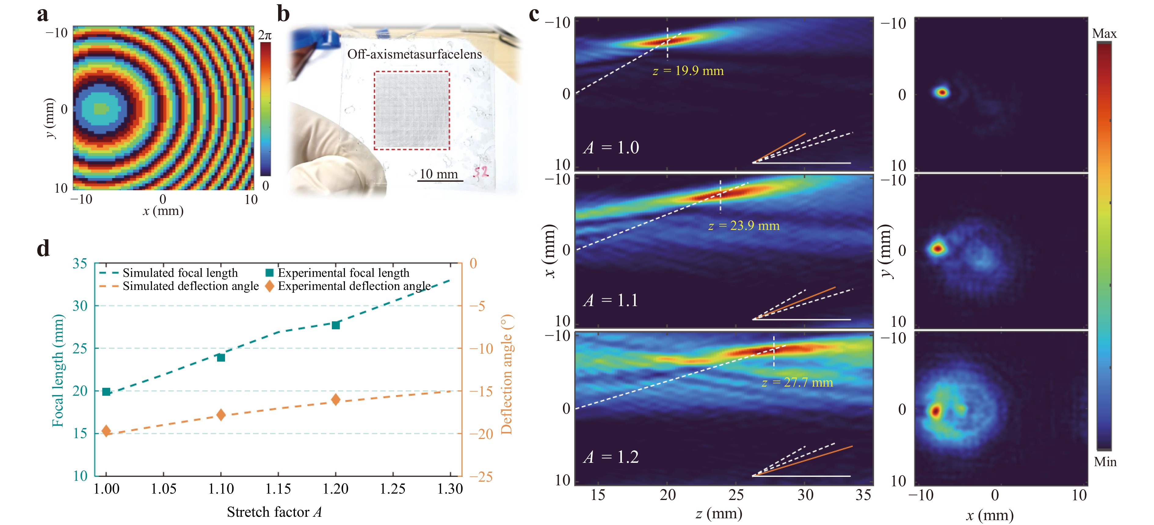
Fig. 4 Characterisation of the tuneable off-axis metasurface lens under mechanical stretching. a Quantified phase distribution of the off-axis metasurface lens with (20 mm, 20°) at 0.35 THz. b Photograph of the fabricated SWCNT-based off-axis metasurface lens. c Intensity distributions in the propagation (xz) plane and each focal (xy) plane under various stretch factors (A = 1.0, 1.1, 1.2). d Experimental and simulated results of axial focal length and deflection angle with different stretch factors.
In the unstretched state (A = 1.0), the measured focal position is (19.9 mm, −19.69°), which exhibits a slight deviation from the design target (20 mm, −20°). This discrepancy primarily arises from the position and limited effective aperture of the detection crystal (a circular area with a diameter of only 15.4 mm), which truncates the diffracted field and loses some optical field information. To account for this experimental constraint, numerical simulations incorporating the finite detection window are performed. Optical field intensity distributions in the propagation (xz) plane under various stretch factors are provided (see Note 4 in Supporting Information).
To observe the beam deflection more clearly, both measured and simulated axial focal lengths and deflection angles are summarised in Fig. 4d. Furthermore, the key performance metrics are listed in Table 2. As the sample is progressively stretched, the axial focal length gradually increases, while the deflection angle gradually decreases. Experimentally, the axial focal lengths are 19.9, 23.9 and 27.7 mm, while the corresponding beam deflection angles are −19.69°, −17.80° and −16.01° for stretch factors of A = 1.0, 1.1 and 1.2, respectively. Relative to the unstretched state (A = 1.0), these values represent angular shifts of +1.89° and +3.68°. In the simulation, the axial focal lengths are 19.6, 24.4 and 28.0 mm, with deflection angles of −20.11°, −17.92° and −16.30°, respectively, yielding relative shifts of +2.19° and +3.81°. The comparison reveals that, at a stretch factor of A = 1.1 and A = 1.2, both axial focal length and transverse deflection angle exhibit smaller changes in the experiment than in the simulation. This discrepancy suggests that the actual stretching applied to the sample during the experiment was insufficient. The precise control of the stretching amount with our sample holder remains challenging.
Stretch factor Method Focal length f (mm) Beam steering angle θ (°) A = 1.0 Numerical simulation 19.6 −20.11° Experimental 19.9 −19.69° A = 1.1 Numerical simulation 24.4 −17.92° Experimental 23.9 −17.80° A = 1.2 Numerical simulation 28.0 −16.30° Experimental 27.7 −16.01° Table 2. Comparison of focal length and beam steering angle for different stretch factors.
-
Unlike conventional plasmonic metasurfaces, which rely on metallic patterns that are prone to cracking under strain, our SWCNT-based design leverages the intrinsic elasticity and high electrical conductivity of the nanotubes to maintain optical functionality over repeated deformation cycles (see Supplementary video). To further validate the device's robustness, we systematically tested the focusing characteristics of the SWCNT-based metasurface lens under multiple stretch-release cycles (N = 50, 100, 500, and 1,000) at a stretch factor of A = 1.2. Fig. 5a, b present the optical field distributions at the corresponding focal planes after different numbers of stretch-release cycles, for the sample in the released (A = 1.0) and stretched (A = 1.2) states, respectively. All intensity profiles are normalised to the maximum intensity obtained at N = 50 and A = 1.0. To further elucidate the evolution of the focal properties, the axial intensity distributions along the propagation axis and transverse intensity profiles at the focal plane are extracted and presented in Fig. 5c, d, respectively. As observed, even after 1,000 stretch-release cycles, the sample does not exhibit significant changes in either focal length or DOF. Moreover, both focal spot size (defined as the full width at half maximum (FWHM) of the focal spot) and peak focal intensity exhibit negligible variations in both released and stretched states. Detailed focusing characteristics, including the focal length, DOF, focal spot size, and peak intensity, are summarised in Table 3. Collectively, these results demonstrate the excellent mechanical and optical stability of our devices.
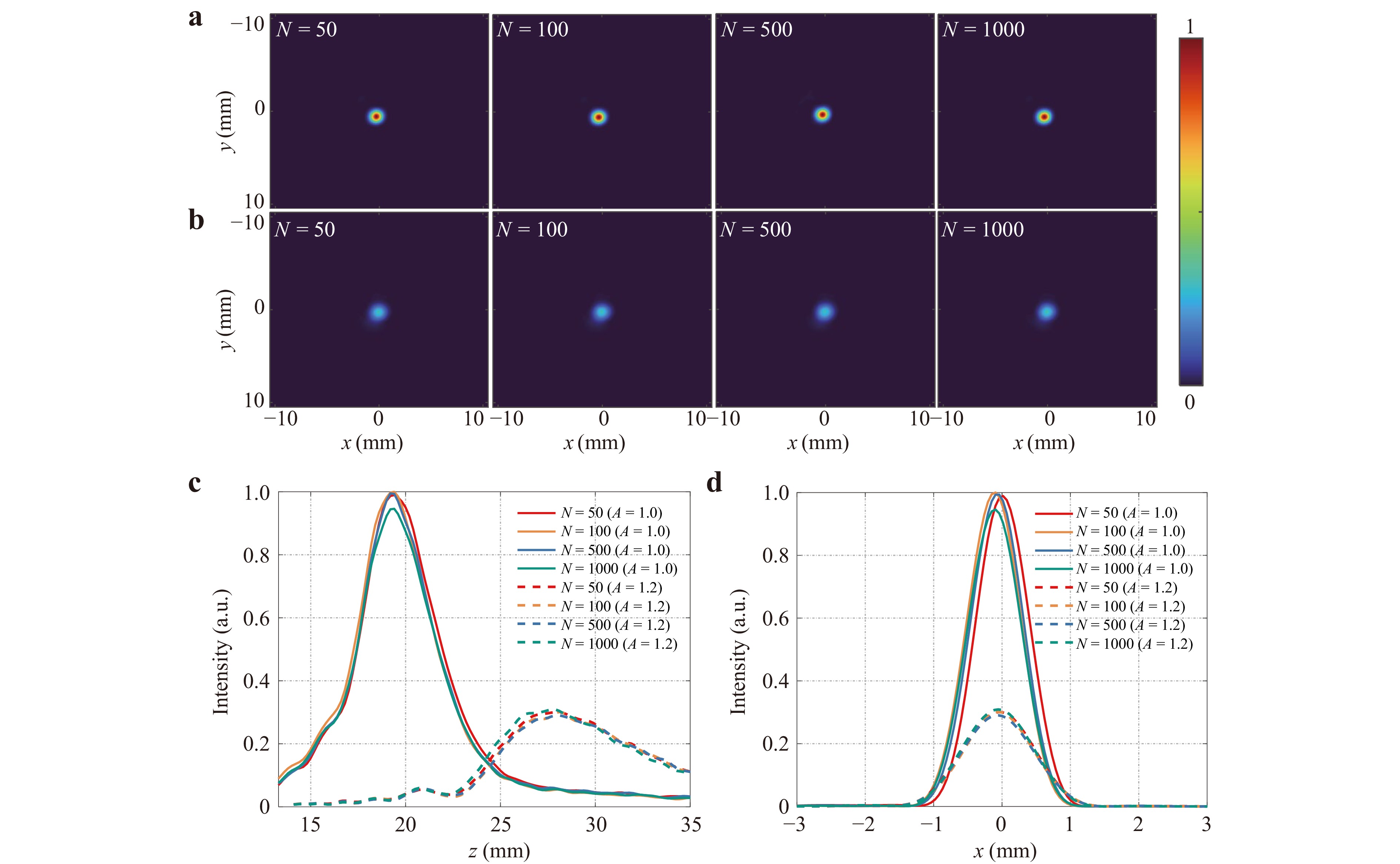
Fig. 5 Measured focusing characteristics of the SWCNT metasurface lens under multiple stretc-release cycles. a, b Normalised optical field distributions at the respective focal planes after 50, 100, 500, and 1,000 cycles for A = 1.0 and A = 1.2, respectively. c Axial intensity profiles along the propagation axis. d Transverse intensity profiles at the focal plane.
Stretch
factorCycle
number NFocal length
f (mm)DOF
(mm)Focal spot
size (mm)Normalised focal
intensity (a.u.)A = 1.0 50 19.4 1.6 0.88 0.99 100 19.4 1.4 0.83 1.00 500 19.2 1.2 0.83 0.99 1000 19.4 1.4 0.88 0.95 A = 1.2 50 27.9 3.4 1.21 0.30 100 28.1 2.6 1.10 0.30 500 28.1 3.0 1.21 0.29 1000 27.9 2.8 1.16 0.31 Table 3. Focusing characteristics of the SWCNT-based metasurface lens under multiple stretch-release cycles.
In this study, we propose and experimentally demonstrate reconfigurable SWCNT-based THz metasurfaces, whose optical response can be dynamically manipulated via mechanical stretching. The fundamental phase-tuning unit of the metasurface consists of SWCNT-based rods patterned on a silicone substrate, with their azimuthal orientations designed according to the PB phase principle. By harnessing the PB phase in the design of the fundamental phase-tuning unit, we realise a phase-modulating THz metasurface capable of wavefront manipulation. Two functional devices (a tuneable-focus metasurface lens and off-axis metasurface lens) are experimentally demonstrated. For the tuneable-focus metasurface lens, stretching enables continuous tuning of the focal length. When the sample is stretched to 1.2 times its original length, the focal length increases from 19.4 to 28.2 mm, corresponding to an increment of 8.8 mm (a change of 45% relative to the initial focal position), and highlights the high sensitivity of the device to mechanical deformation. For the off-axis SWCNT-based metasurface lens, the stretching simultaneously drives longitudinal displacement and transverse deflection of the focal spot. At a stretch factor of 1.2, the beam deflection angle changes from −19.69° to −16.01°, corresponding to a relative steering angle of +3.68°. Critically, repeated stretch-release cycles confirm that both samples exhibit excellent mechanical and optical stabilities.
These results highlight that the combination of advanced nanomaterials such as SWCNTs with metasurface design provides a promising solution for flexible THz wavefront control. This strategy effectively resolves the trade-off between tuneability and mechanical robustness in flexible photonics. It opens new avenues for development of smart, lightweight, and wearable THz components, laying the groundwork for fully programmable and adaptive photonic platforms in 6G communication, sensing, and imaging technologies.
-
Patterned thin films of SWCNTs for metasurfaces were fabricated using the aerosol (floating catalyst) chemical vapour deposition (CVD) method40, which relies on CO decomposition via the Boudouard reaction on Fe-based catalyst aerosol particles. The pristine SWCNT film, consisting of a network of randomly oriented nanotubes, was patterned to form the metasurface structure. The thickness of the deposited film was optimised to balance electrical conductivity and structural integrity, ensuring a sufficient amplitude contrast for an effective metasurface operation. The patterning procedure, following reported approaches41, employed a SWCNT film as an opaque region (in contrast to the highly transparent bare substrate) of the metasurface. First, a custom metasurface pattern was etched into a stainless-steel plate by pulsed laser ablation, producing a rigid stencil with a relief depth of 150–200 µm. The pattern was then transferred onto a nitrocellulose filter (HAWP, Merck Millipore; pore size: 0.45 µm) by passing the filter, affixed to the stencil, through rollers to locally compress selected pore areas and reduce the permeability, while the engraved recesses left the filter unaffected. An SWCNT aerosol was then deposited onto the uncompressed regions of the filter to form a thin nanotube film that replicated the stencil geometry. Finally, the film was dry-transferred onto a silicone substrate42. Fig. 6 presents an optical microscopy image of the fabricated SWCNT-based metasurface. Notably, the SWCNT film patterns are characterised by a high resolution of the reproduced geometry with sharp edges and almost complete absence of nanotubes in the gaps between parts of the pattern.
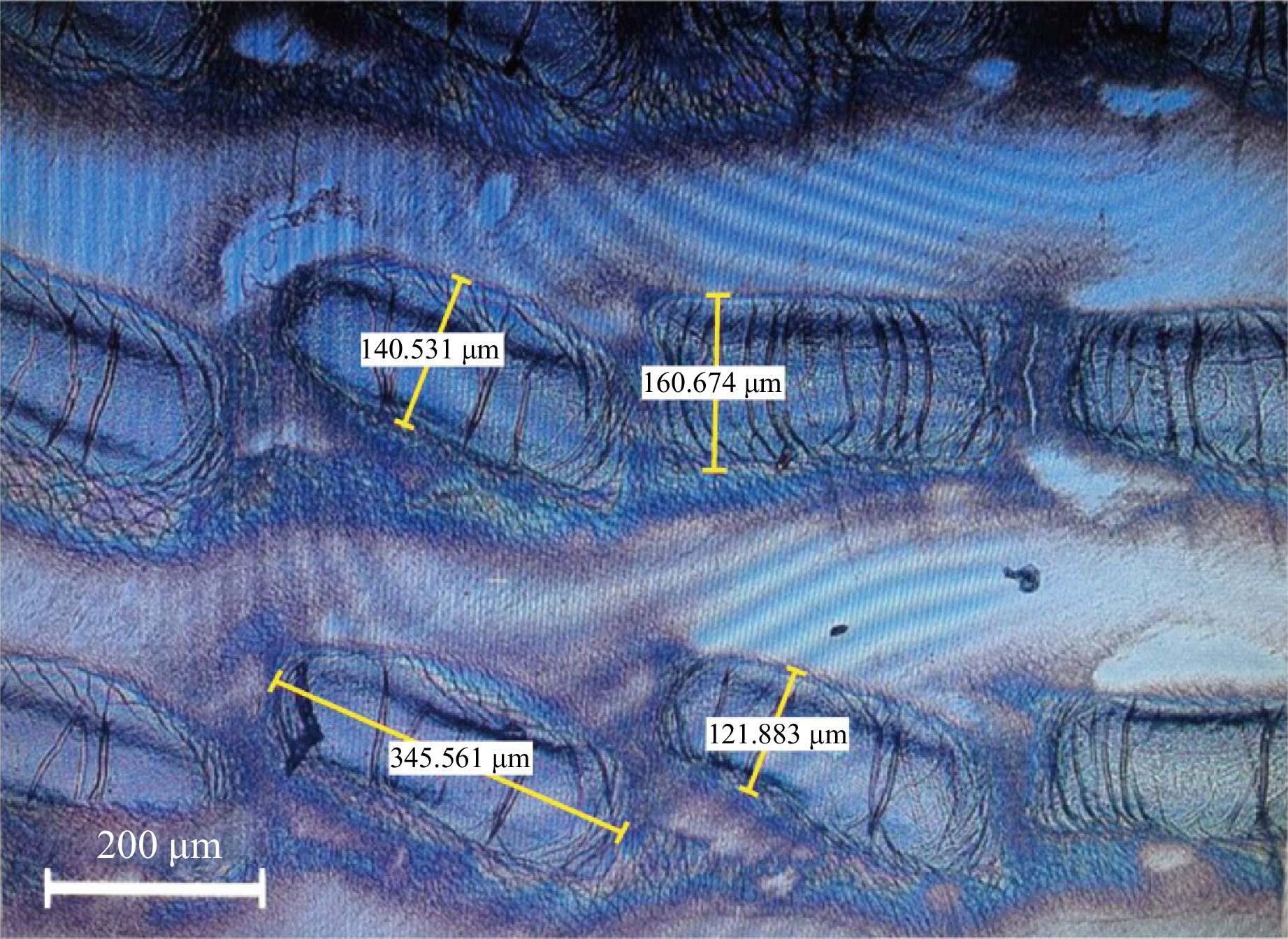
Fig. 6 Optical microscopy image of the fabricated SWCNT-based metasurface.
To evaluate the mechanical robustness and electromagnetic stability of the fabricated SWCNT film under strain, its THz transmission properties were characterised during the stretching process. Fig. 7a shows an ~80 nm-thick SWCNT film (diameter: 31 mm) mounted in the stretching holder, which exhibits a uniform macroscopic appearance. The sample was uniformly stretched simultaneously in all directions, and the corresponding THz transmission spectra were measured by a single-point continuous-wave THz intensity detector at different stretch factors, as shown in Fig. 7b. Notably, the spectral fluctuations observed in Fig. 7b are partly attributed to the sensitivity of the single-point THz intensity detector to environmental conditions, particularly variations in humidity and temperature. Atmospheric water vapour absorption can introduce a significant noise in the THz regime. Future measurements employing a THz time-domain spectroscopy system (THz-TDS) within a sealed, nitrogen-filled, and thermostatic enclosure are expected to significantly suppress these environmental artefacts and provide a more precise characterisation of the film's intrinsic frequency response. Despite these fluctuations, the results demonstrate that the transmission of the film in the range of 0.22–0.37 THz remained stable at approximately 0.4 for both unstretched (A = 1.0) and stretched (A = 1.2) states. This confirms the excellent mechanical and electromagnetic stabilities of the SWCNT film under deformation. Fig. 7c presents the spatial intensity variation of a 0.35 THz wave before and after passing through the SWCNT film, as detected by a high-sensitivity THz detector. When the SWCNT film was continuously stretched, the transmission of the 0.35 THz wave was recorded, as shown in Fig. 7d. These results demonstrate that the THz wave transmission maintained a good stability under continuous tensile strain. The stretchability of the film provides a unique platform for an active control of its THz interactions, which is essential for development of tuneable and functional THz devices.
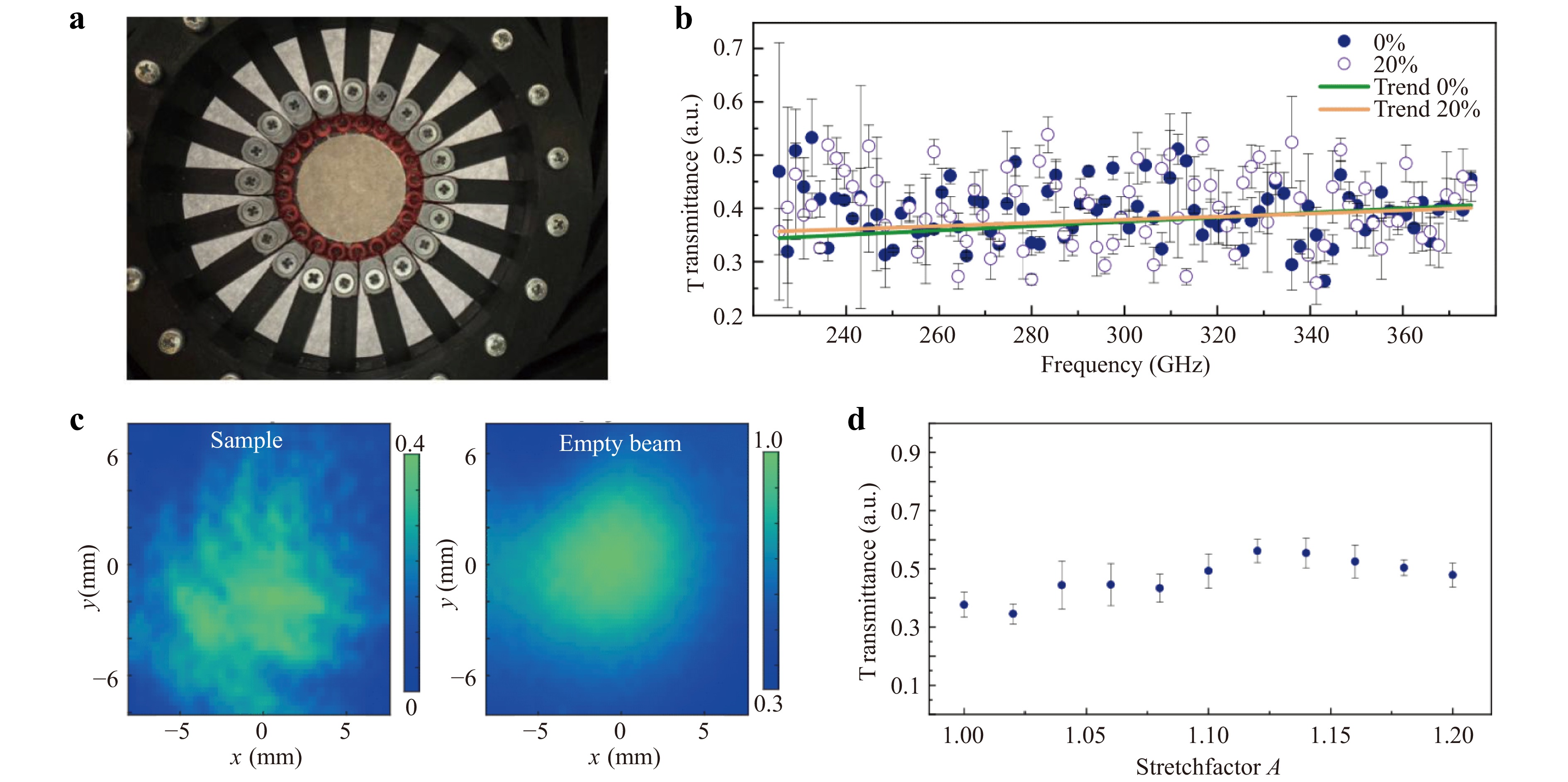
Fig. 7 Morphology and THz transmission characteristics of the SWCNT film under varying stretch states. a Photograph of the fabricated SWCNT film (diameter: 31 mm) in the stretching holder. b THz transmission spectra at stretch factors of 1.0 and 1.2. c Intensity distribution of the 0.35 THz wave before and after transmission through the SWCNT film. d Transmission of the 0.35 THz wave through the SWCNT film under continuous stretching.
-
In the experiment, a THz polarisation holographic imaging system was employed to detect the RCP component of the THz field modulated by the metasurface. A schematic of the optical setup is shown in Fig. 8. A laser with a central wavelength of 800 nm, pulse width of 100 fs, and repetition rate of 1 kHz was split into two beams. One of them served as a pump beam for generation of the THz wave, while the other as a probe beam for detection of the THz field. The pump beam, after passing through a concave lens, impinged on a <110>-cut ZnTe crystal (ZnTe1), generating a linearly polarised THz pulse with a bandwidth of 0.2–2.6 THz. A quarter-wave plate (QWP) (for 0.35 THz) was employed to convert the THz wave into a LCP state. The diverging LCP THz beam was reflected by an off-axis metallic parabolic mirror (PM), which collimated and expanded it into a parallel beam with a diameter of 20 mm, incident normally onto the metasurface. The THz wave modulated by the metasurface was detected by another <110>-cut ZnTe crystal (ZnTe2).
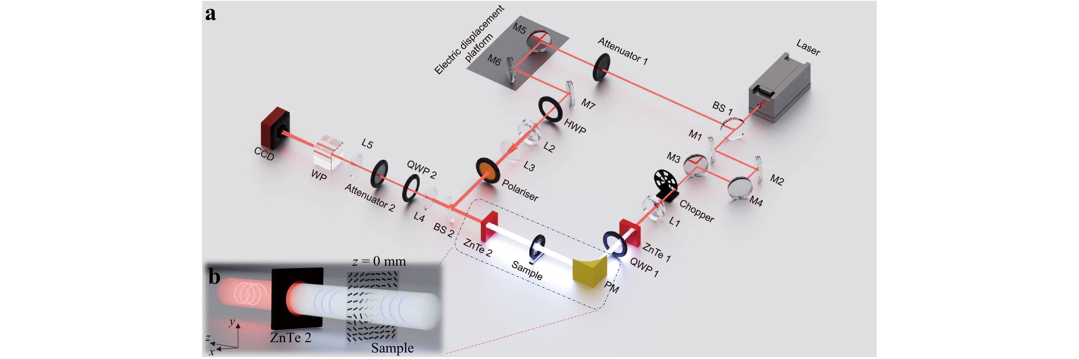
Fig. 8 Schematic of the experiment setup: THz polarisation holographic imaging system (BS: beam splitter, M: mirror, HWP: half-wave plate, L: lens).
In the probe path, the probe beam was expanded to a collimated beam with a diameter of 20 mm using a telescope composed of a concave lens and convex lens. It was then reflected by a 5:5 beam splitter onto the detection crystal (ZnTe2). Within ZnTe2, the probe beam was modulated by the THz field and reflected from the crystal's back surface back into an imaging module. This module consisted of two convex lenses, QWP, Wollaston prism (WP), and charge-coupled device (CCD) camera. The WP separated the horizontally and vertically polarised components of the probe beam, enabling a simultaneous acquisition of two orthogonal polarisation images on the CCD. The CCD was synchronised with a chopper in the pump path. THz field information was acquired using the balanced electrooptic detection technique37. A motorised delay line was introduced into the probe path for scanning of the THz time-domain information with a step size of 0.02 µm. The complex field (amplitude and phase) at an arbitrary frequency was obtained via Fourier transform.
The horizontal (Ex) and vertical (Ey) polarisation components of the THz field can be acquired by varying the angle between the probe beam's polarisation direction and <001> axis of the detection crystal38. In our experiment, the RCP THz field was obtained by $ {E}_{\rm{RCP}}=({E}_{x}+i{E}_{y})/\sqrt{2} $. The THz field intensity distribution map can be calculated by $ I={\left| {E}_{\rm{RCP}}\right| }^{2} $.
-
J. H. and Y. Z. acknowledge National Natural Science Foundation of China (Project Nos. 62005020 and 12574421). A.V.R. and M.G.B acknowledge Ministry of Science and Higher Education (Project No. FSMG-2025-0005). A.G.N. acknowledges Russian Science Foundation (Project No. 22-13-00436-П; SWCNT synthesis). We are thankful to Dr. Ignat I. Rakov for fruitful discussions on SWCNT patterning.
Dynamic terahertz wavefront control using stretchable single-walled carbon nanotube-based metasurfaces
- Light: Advanced Manufacturing , Article number: 66 (2026)
- Received: 31 December 2025
- Revised: 11 April 2026
- Accepted: 13 April 2026 Published online: 26 May 2026
doi: https://doi.org/10.37188/lam.2026.066
Abstract: The terahertz (THz) technology has a pivotal role in advancing next-generation communication systems, offering distinctive advantages for high-speed data transmission and precise sensing. Concurrently, flexible functional devices have emerged as a key research focus due to their ability to conform to complex application scenarios through mechanical deformation. The integration of THz wavefront manipulation with flexible platforms is crucial for unlocking innovative applications. However, existing devices often lack the dynamic tunability required for practical implementation. Here, we demonstrate two types of flexible THz metasurfaces for phase modulation based on the Pancharatnam-Berry phase modulation, operating at 0.35 THz. Each device comprises an array of single-walled carbon nanotube resonators on a silicone substrate. The first design is a mechanically tuneable metasurface lens. Under a stretch factor of A = 1.2, the focal spot shifts rearwards, and the focal length increases from 19.4 to 28.2 mm (an increment of 8.8 mm). The second design enables dynamic beam deflection through controlled mechanical stretching. At the same stretch factor (A = 1.2), the deflection angle varies from −19.69° to −16.01°, with a change of 3.68°. These results provide a viable technical pathway for dynamic THz wavefront modulation, laying a solid foundation to enhance THz applications in future communication systems and expand the potential of flexible devices in high-frequency electromagnetic fields.
Research Summary
Terahertz optics: Stretchable metasurfaces enable dynamic beam control
Terahertz technology is pivotal for next-generation communication and sensing, yet flexible, dynamically tunable wavefront devices remain limited. We demonstrate stretchable terahertz metasurfaces based on single-walled carbon nanotubes with Pancharatnam–Berry phase modulation for dynamic wavefront control at 0.35 THz. Mechanical stretching enables tunable focal shift and beam deflection. Our design exhibits strong stability and retains performance even after thousands of repeated stretching cycles. This strategy addresses the lack of real-time tunability in conventional THz components, offering a simple, robust pathway for reconfigurable terahertz devices. The technology holds promise for future 6G wireless communications, adaptive imaging, and wearable THz sensors.
Rights and permissions
Open Access This article is licensed under a Creative Commons Attribution 4.0 International License, which permits use, sharing, adaptation, distribution and reproduction in any medium or format, as long as you give appropriate credit to the original author(s) and the source, provide a link to the Creative Commons license, and indicate if changes were made. The images or other third party material in this article are included in the article′s Creative Commons license, unless indicated otherwise in a credit line to the material. If material is not included in the article′s Creative Commons license and your intended use is not permitted by statutory regulation or exceeds the permitted use, you will need to obtain permission directly from the copyright holder. To view a copy of this license, visit http://creativecommons.org/licenses/by/4.0/.

 DownLoad: