




-
In the 17th century, Danish scientist Bartholin noted the peculiar image-doubling phenomenon in calcite, marking the first record of birefringence. Birefringence fundamentally arises from the orderly internal arrangement of transparent media and is manifested as anisotropic refractive indices in different directions1. In anisotropic media, orthogonal polarisation components have different refractive indices, leading to beam splitting and optical path differences2. Here, the refractive index depends not only on the wavelength and the material itself but also on the propagation direction and polarization orientation3. In particular, the polarisation eigenstates of light manifest as two mutually orthogonal linear polarisation states with linear birefringence. Ordinary light follows the classical Snell’s law, whereas extraordinary light requires solving Snell’s law together with the refractive-index ellipsoid equation to determine the actual direction of its wave vector and effective refractive index4,5. In modern photonics and engineering, birefringence not only possesses profound physical significance, but also serves as an indispensable parameter for polarisation control and sensing in engineering applications, forming the foundation of polarization optics6. On the one hand, by artificially controlling the birefringence properties of materials, it is possible to actively and precisely manipulate the propagation path and polarization state of light, enabling broad applications in metasurface-based wavefront and polarization control7, optical communication8, advanced display technologies9, as well as photonic and optical instrumentation systems10. On the other hand, the intrinsic birefringence of materials can passively and intuitively reveal their internal structures and characteristics, offering powerful analytical tools for materials science11, biomedical sciences12, and advanced optical detection techniques.
In recent years, transparent media13 as core components of high-end optical systems in fields ranging from large scientific instruments to micro-precision platforms have seen a continuously growing demand for birefringence analysis and measurement13,14. This trend stems from the unique capability of birefringence to reveal optical anisotropy, stress distribution, and microscopic structural orientation within materials. By measuring the birefringence, subtle internal details that are otherwise inaccessible through conventional methods can be determined. Transparent media, such as glass, crystals, polymer films, and biological tissues, often exhibit slight but physically meaningful birefringence effects under processing, operational conditions, or external fields, reflecting internal structural states and stress variations15. With the advances in optical manufacturing, micro/nanophotonics, and biomedical imaging technologies, there is an increasing demand for high-sensitivity, high-resolution birefringence measurement techniques. For instance, birefringence is used in fabrication to assess stress nonuniformity15. In the biomedical field, birefringence in tissue sections or live samples is used to identify collagen fibre orientation and detect tumour architecture, thereby providing label-free, high-contrast imaging16. Furthermore, the emergence of functional materials17, such as two-dimensional materials, anisotropic metamaterials, and strain-tunable media, has introduced complex polarisation responses, making birefringence characterisation an essential tool for material development and performance evaluation. Therefore, the accurate measurement of birefringence parameters is crucial for investigating internal structures of materials, designing advanced polarisation optical devices, analysing component stress and defects, and imaging biological tissues.
The polarisation state of light directly reflects the birefringence characteristics of a material, prompting extensive research on optical polarisation methods18. Compared to traditional techniques such as mechanical testing, electron microscopy, and X-ray diffraction, polarisation-based methods, which leverage the sensitivity of the polarisation state to differences in refractive indices, enable non-contact, non-destructive, and quantitative measurements with superior sensitivity, spatial resolution, and real-time imaging19,20. In this review, recent advances in birefringence measurement techniques based on polarisation for transparent media are systematically surveyed, providing a comprehensive analysis of their physical basis, technical implementations, and representative applications, as illustrated in Fig. 1. This review begins by presenting the fundamental types of birefringence—natural, engineered, and field-induced—and then classifying representative materials according to their characteristic birefringence parameters. Building on a unified Jones-Mueller formalism and the corresponding method-specific measurement mechanisms, this review emphasises polarimetric modulation analysis methods, interferometric measurement approaches, and other polarisation measurement techniques. In the modulation analysis category, the performance parameters, modulation strategies, and application adaptabilities of various modulators are compared. Within the interferometric methods, the optical configurations and technical features of different interferometers are systematically analysed and contrasted. In addition to these mainstream approaches, measurement principles and characteristics of alternative methods are discussed. The application section summarises the practical implementation of birefringence measurement techniques in fields, such as stress analysis, material characterisation, biological tissue imaging, and optical component calibration. A comparative table outlines the advantages and limitations of the different measurement methods in terms of accuracy, system complexity, and applicable range. Finally, the review concludes with a discussion on the current technical challenges and future development directions. This review aims to provide a clear, comprehensive, and balanced technical reference for researchers in the field of polarisation optical measurements and to guide future innovations in birefringence metrology.
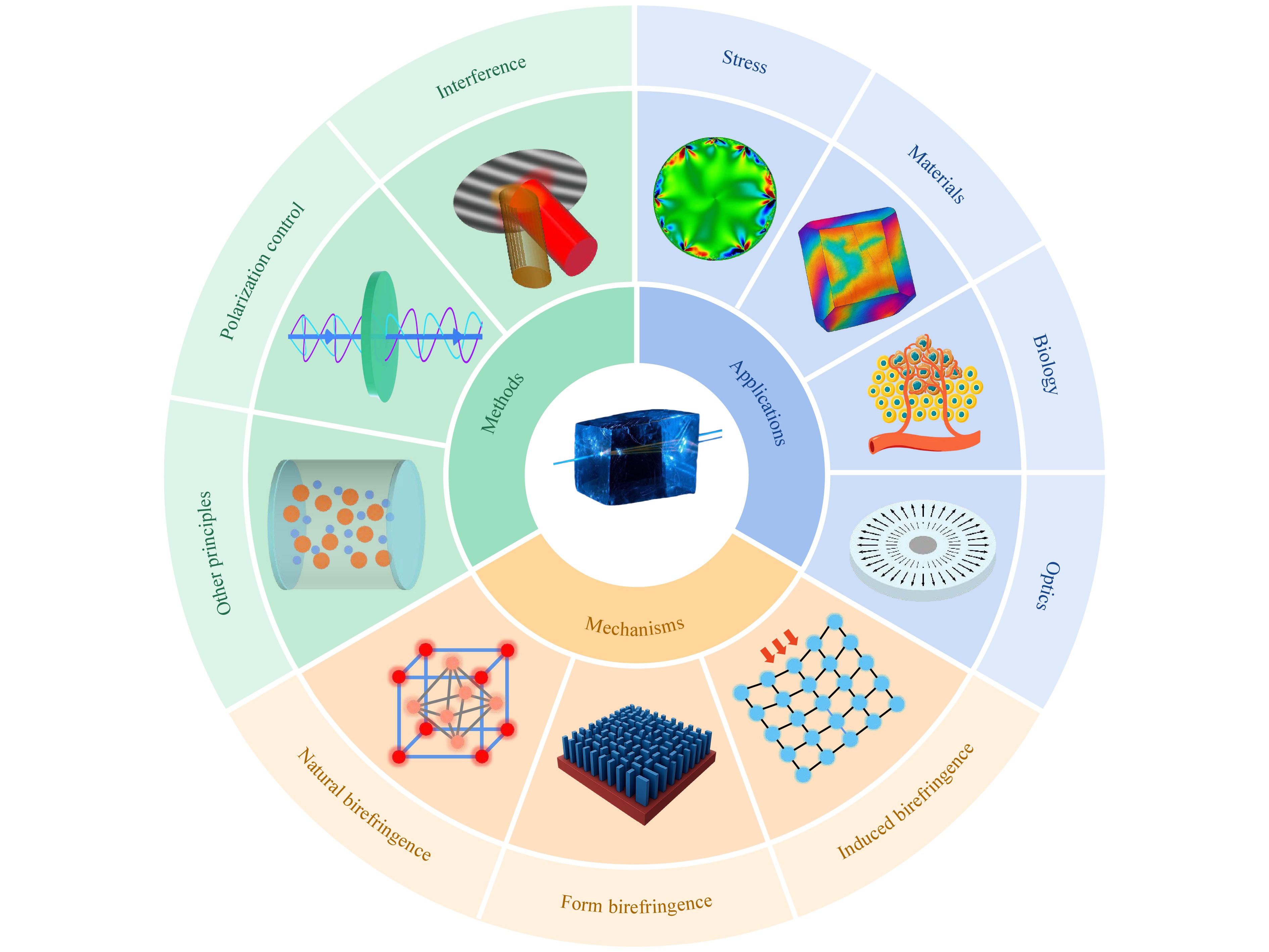
Fig. 1 Overview of mechanisms, methods, and applications of linear birefringence.
-
The anisotropy of molecular arrangements in transparent media causes different polarisation propagations with different refractive indices, fundamentally causing birefringence. According to electromagnetic and crystal-optical theories, birefringence arises from the anisotropy of the refractive index tensor of the medium, represented by index ellipsoids with unequal axes21. The index ellipsoid visually depicts how the refractive index of a crystal varies with beam direction and polarisation state. The length of the semi-axis of the ellipsoid in a given direction represents the refractive index in that direction22. In isotropic materials, the refractive-index ellipsoid degenerates into a sphere (Fig. 2a), yielding only one refracted beam that follows Snell’s law. Anisotropic crystals have two ellipsoids corresponding to the orthogonal ordinary (o) and extraordinary (e) waves. There can be one or two special directions in anisotropic crystals called optical axes, along which light does not experience birefringence. When light enters in any direction (Fig. 2b), it splits into o- and e-waves with different indices and velocities, which refract separately and produce birefringence. Along the optical axis (Fig. 2c), the ordinary and extraordinary refractive indices become identical, therefore the medium behaves isotropically. However, perpendicular non-axial incidence (Fig. 2d) yields same-direction refraction with a phase shift. This phenomenon is widely applied to active or passive control of light polarisation. This review focuses on measuring the birefringence in such samples, characterised by two equally important parameters: phase retardance, which determines the phase difference introduced between the two polarisation components, and retardance axis orientation (fast or slow), which determines the direction of polarisation decomposition.
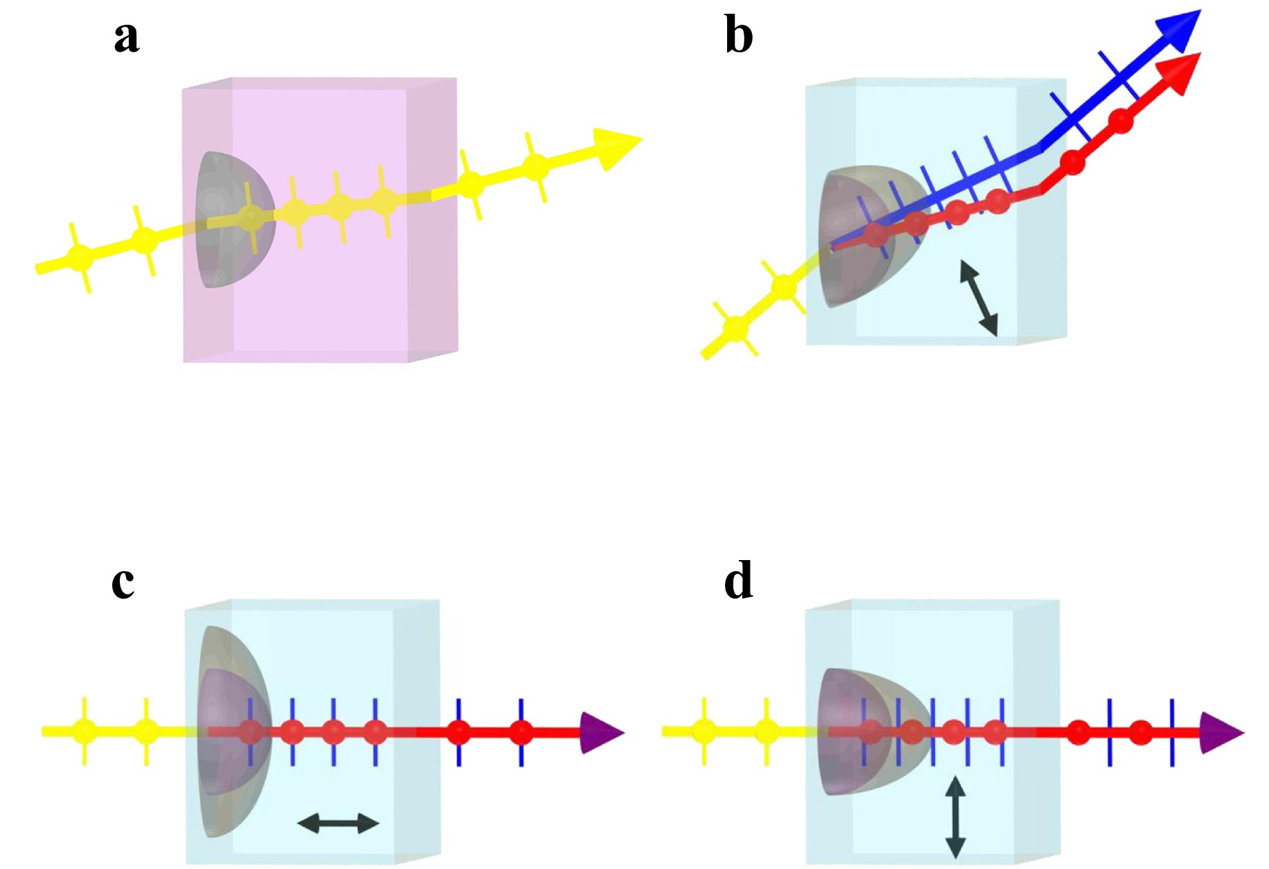
Fig. 2 Illustration of birefringence. Light propagates in an isotropic crystal a and positive uniaxial anisotropic crystal with different incident directions b-d. b Incident from an arbitrary/general direction. c Incident along the optical axis. d Incident perpendicular to the optical axis.
-
The mechanisms responsible for birefringence can be classified as natural, engineered, and induced. Natural birefringence23 stems from the intrinsic anisotropy of the crystal structure of the material, that is, the asymmetrical arrangement of atoms or molecules along different spatial directions, which causes the crystal to exhibit different refractive indices for different polarisation states. Engineered birefringence24 arises from artificially introduced subwavelength anisotropic structures rather than from inherent properties of the material. This mechanism allows precise control over the birefringent behaviour by designing the geometry, orientation, and distribution of the structural elements at the nanoscale. Induced birefringence25,26 refers to the additional birefringence generated in a material by external influences such as stress, electric fields, magnetic fields, optical fields, and temperature changes.
Natural birefringence most commonly occurs in crystalline materials. In non-cubic crystals, the dielectric tensor becomes direction-dependent, endowing the crystal with an inherent birefringence. Crystals can be classified as uniaxial, having a single optical axis (e.g. calcite and quartz), or biaxial, having two optical axes (e.g. sodium nitrate and borax). Uniaxial crystals can be distinguished on the basis of their principal refractive indices. Positively uniaxial crystals satisfy nₑ > nₒ (e.g., quartz), whereas negatively uniaxial crystals satisfy nₑ < nₒ (e.g., calcite). Natural birefringence also occurs in certain polymeric materials. For example, uniaxially stretched polymer films exhibit inherent birefringence owing to their molecular orientation27. Additionally, some biological organic crystals, such as cellulose and collagen fibrils in corneal tissue28, naturally exhibit birefringence. The differential interaction of polarised light provides the required contrast for biological polarisation imaging. It should be noted that natural birefringence varies with wavelength (material dispersion), yet is intrinsically a property of the material.
Engineered birefringence, also known as form birefringence, arises from the artificial structuring of isotropic materials into anisotropic sub-wavelength patterns. When the structural periodicity is significantly lower than the incident wavelength, the medium is regarded as an effective anisotropic material. This effective birefringence originates from the differences in the local dielectric constants and geometrical asymmetry, which induce distinct effective refractive indices for orthogonal polarisations. Under these conditions, the nanostructured region behaves as an effective medium, exhibiting optical anisotropy even though the constituent materials are isotropic. As schematically illustrated in Fig. 3a, a typical unit structure consists of an asymmetric dielectric inclusion embedded in a substrate. By adjusting the geometric parameters such as length, width, height and orientation angle, one can precisely tune both the phase retardance and retardance axis orientation of the birefringence. Rather than being confined to simple rectangular geometries, anisotropic building blocks can adopt a wide variety of cross-sectional profiles, including elliptical29, trapezoidal30, and even freeform or irregular shapes31 enabled by inverse and topology-optimisation design strategies. Meanwhile, the birefringent response can be further engineered through diverse structural configurations, such as multilayer or cascaded architectures32, concentric and composite meta-atoms33, as well as spatially graded arrangements with continuously varying geometrical parameters34, thereby providing substantially expanded degrees of freedom for tailoring the effective birefringence. Thus, the engineered birefringence offers a powerful platform for realising compact, flat, and multifunctional photonic devices using subwavelength dielectric metastructures and metasurfaces with tailored polarisation properties.
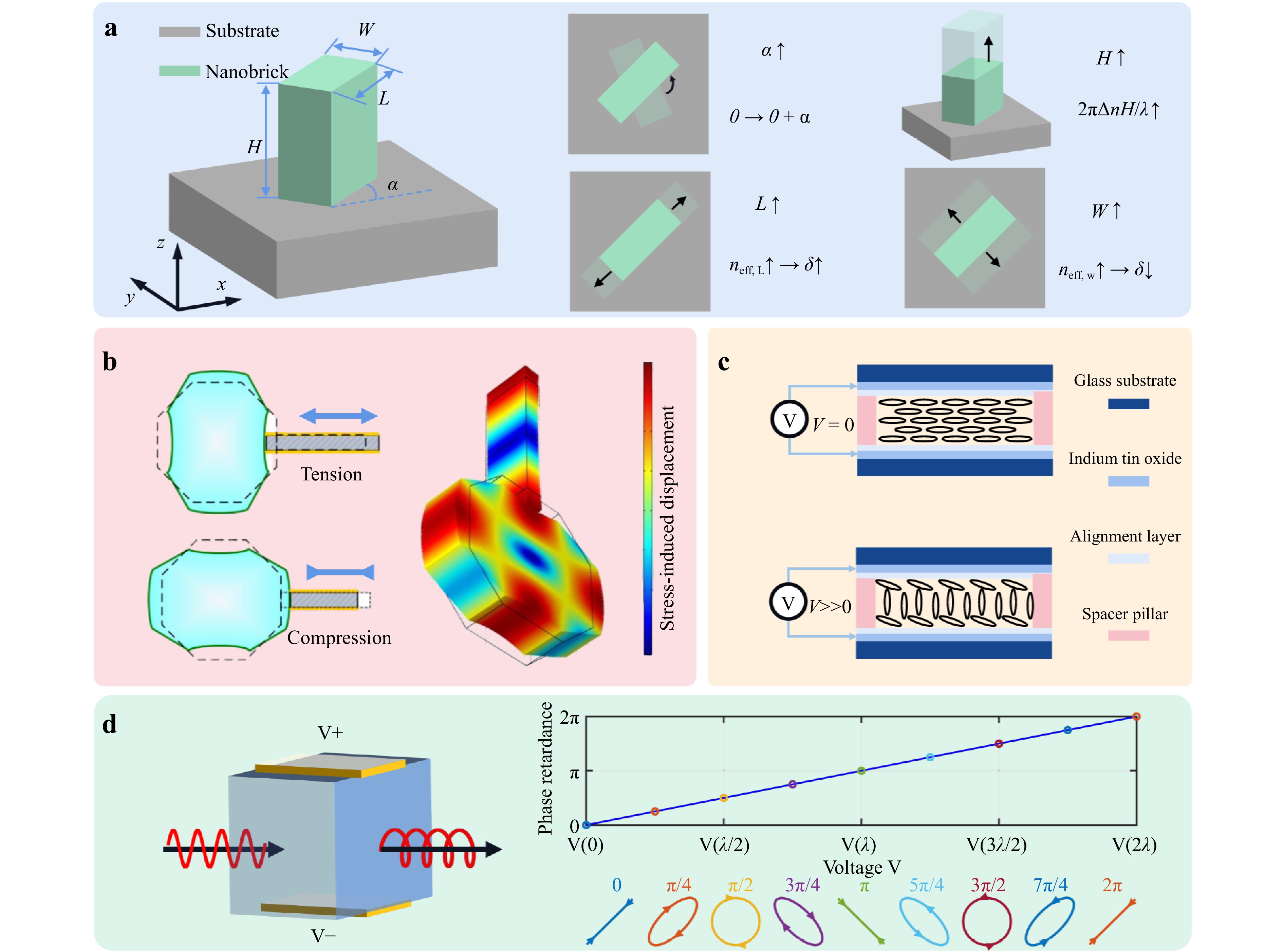
Fig. 3 Birefringence mechanism. a Engineered birefringence mechanism demonstrated by anisotropic metasurface nanobricks: the effective refractive indices along the long and short axes (neff,L and neff,W) are independently controlled by the geometry of the nanobrick (length L, width W, height H) and in-plane rotation angle α, enabling tunable phase retardance δ and fast-axis orientation θ. b Stress-induced birefringence mechanism demonstrated via photoelastic modulator (PEM): stress induces optical anisotropy and displacement. c Electrically induced birefringence mechanism demonstrated via liquid crystal variable retarder (LCVR): voltage alters liquid crystal alignment; d Electrically induced birefringence mechanism demonstrated via electro-optic modulator (EOM), enabling phase-voltage response and polarization control.
Induced birefringence is a controllable effect that can be classified into the following types based on the induction mechanism. Stress-induced birefringence refers to the additional birefringence generated when a material experiences external mechanical or internal residual stress. The orientation of the retardance axis is directly linked to the principal stress direction in the material, and the magnitude of the phase retardance is quantitatively related to the stress through the photoelastic coefficient of the material. Stress-induced birefringence has two major engineering roles. It is widely used for the non-destructive inspection of internal stress in transparent media35. Optical glasses, lenses, polymers, and other transparent components often accumulate residual stress during fabrication and during cooling. Although these stresses are not visible through conventional visual inspection, they introduce slight direction-dependent changes in the refractive index. By measuring the birefringence, one can infer the magnitude, direction, and spatial distribution of internal stresses, thereby enabling quality control and process optimisation. Conversely, stress-induced birefringence can be precisely and actively controlled and applied36. In a photoelastic modulator (PEM)37, mechanical or piezoelectric actuators impose high-frequency stress to dynamically tune the refractive index and rapidly modulate the polarisation (Fig. 3b). It is widely used for laser intensity modulation, beam stabilisation, and precision polarisation control.
Electrically induced birefringence refers to the controlled differences in the refractive indexes under an applied electric field that causes birefringence. This effect enables dynamic phase delay modulation and is a core mechanism in optical control devices. Electrically induced birefringent materials include electro-optic (EO) crystals and liquid crystals (LC)38. EO crystals (e.g., LiNbO3, KDP, BBO) use Pockels or Kerr effects to linearly or nonlinearly alter the refractive index tensor under an electric field, enabling precise polarisation and phase control (Fig. 3d). These devices respond in nanoseconds to picoseconds and are suitable for high-speed modulation39. The LC is a mesophase between ordered and disordered states9,40. The rod-like molecules in nematic LC (Fig. 3c) exhibit optical anisotropy. Application of a field reorients the direction of the LC molecules, altering effective birefringence Δneff and enabling continuous phase retardance. Based on this principle, the LC variable retarder (LCVR) features low voltage, low power, and a simple structure. These two classes of devices are suitable for different modulation speeds and applications and form key implementations of electrically induced birefringence in modern photonics.
Additionally, magnetically, thermally, and photoinduced birefringences, although weaker or condition-dependent, are crucial for certain applications. Magnetically induced birefringence can produce a Faraday rotation (circular birefringence)41. When the magnetic field is aligned with the light path, it creates different refractive indices for the left- and right-circular polarisations, thereby rotating the plane of polarisation. Thermally induced birefringence refers to index changes due to thermal expansion or anisotropy under temperature gradients or heating42. In high-power optics, laser-generated heating in crystals creates temperature gradients, causing anisotropic index changes that distort the polarisation and wavefront, thereby affecting the stability and output quality. Photo-induced birefringence refers to the index anisotropy induced by molecular realignment, isomerisation, or photopolymerization under intense polarised light43. This is observed in photochromic materials and organic polymers, with birefringence persisting post-illumination, forming an “optical memory”. Although weaker and slower, these effects uniquely enable thermal management, light-field control, and functional material studies, enriching induced birefringence mechanisms and applications.
-
Birefringence is typically characterised by two key parameters: phase retardance and retardance-axis orientation. Based on the temporal and spatial variations in these two parameters, common birefringent devices or samples can be categorised as static, dynamic, spatial, and spatiotemporal. Different types of birefringence impose varied technical requirements on the measurement methods used to assess their capabilities.
Static birefringence (Fig. 4a) refers to a fixed phase retardance and defined axis under constant conditions, yielding stable birefringence. Such birefringence is widespread in crystals, as exemplified by wave plates, which serve as core components for polarisation control and modulation44,45. Static birefringence exhibits high repeatability and stability, which makes it suitable for high-precision and high-sensitivity measurements. Such measurements typically require only a single point or minimal sampling to accurately determine the phase retardance and retardance-axis orientation of the material for extracting the intrinsic birefringence coefficients, device quality control, and system modelling.
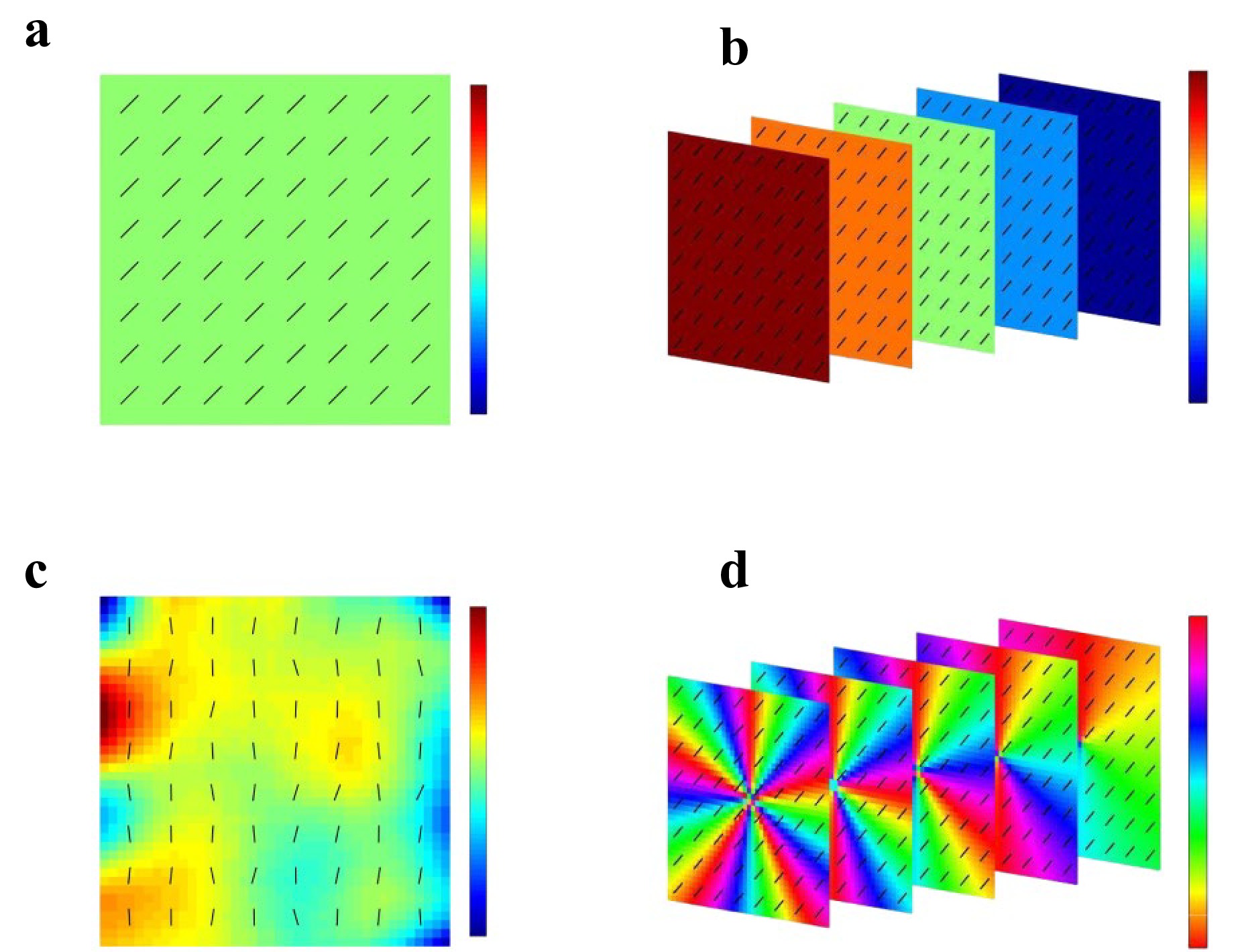
Fig. 4 Birefringence types by parameter characteristics: a static birefringence, b dynamic birefringence, c spatial birefringence and d spatiotemporal birefringence.
Dynamic birefringence (Fig. 4b) varies over time, generally with a fixed axis orientation, but with changing phase retardance. It can be divided into intentional modulation and unintentional drift. Intentional modulation refers to controlling birefringence via externally applied time-varying factors, such as EO modulators (EOM), LCVR, and PEM, thereby giving it an irreplaceable advantage with bandwidths ranging from kHz to GHz. Unintentional drift denotes birefringence fluctuations induced by environmental changes. For example, in fibre applications, the environmental temperature and stress vary diurnally or with loads/disturbances, causing slow drift or random changes in fibre birefringence46. Additionally, processes such as crystal growth, film deposition, and curing cause evolving stress fields or anisotropy accumulation that leads to time-varying birefringence47,48, increasing the demand for real-time monitoring. Dynamic birefringence reflects temporal changes in materials and requires a high temporal resolution in measurement systems. In practice, if the retardance axis remains stable during dynamic birefringence, the polarisation modulation component of the measurement system can be simplified to measure only the dynamic phase retardance, thereby enabling rapid and transient measurements.
Spatial birefringence (Fig. 4c) refers to changes in the phase retardance and axis orientation at different locations, reflecting spatial anisotropy non-uniformity, which is widespread in various natural materials and engineered structures. For example, uneven stress or insufficient annealing can alter the index in different regions of optical components49. Fibres, muscles, and collagens in tissues also exhibit local birefringence owing to variations in orientation and density50. Additionally, vortex half-wave plates (VWP) and metasurface program axis orientation and retardance via spatially patterned anisotropy serve as spatially distributed devices51. Measuring the spatially distributed birefringence in applications requires a certain spatial resolution of the system. Typically, scanning systems acquire point-by-point 2D birefringence maps with high precision and flexibility, whereas wide-field imaging is well suited for large-area measurements. Notably, most spatial birefringence values show continuity or regional correlation, with the birefringent parameters varying gradually rather than randomly.
Spatiotemporal birefringence (Fig. 4d) integrates both temporal and spatial factors. Examples include an LC Spatial Light Modulator (LC-SLM)52 and a tunable element53 whose local birefringence updates rapidly under voltage or field drives, forming real-time tunable phase surfaces. In biomedicine, collagen regeneration and realignment cause local tissue birefringence to change continuously during burn healing, reflecting repair dynamic54. Analysing spatiotemporal birefringence requires capturing large field-of-view changes at a high time resolution, requiring systems with high-speed detection, real-time imaging, and multidimensional processing. Similarly, if the fast-axis orientation remains fixed, the measurement scheme can be significantly simplified, as in dynamic birefringence measurements.
-
Optical polarisation-based birefringence measurement is one of the most important methods for investigating the properties of anisotropic media, and fundamentally relies on detecting changes in the polarisation state of light as it propagates through a birefringent medium. From a technical perspective, birefringence measurement methods are generally categorised into three types: polarimetric modulation analysis methods, interferometric techniques, and other approaches. In recent years, continuous advancements in this field have led to significant improvements in the measurement accuracy and application scope. Regardless of the specific methods of implementation, all of these methods follow the same Jones-Mueller polarisation formalism and can be consistently described within the Jones or Mueller matrix framework.
-
The Jones and Mueller formalisms represent two widely adopted theoretical frameworks for describing the interaction between polarised light and optical media and constitute the fundamental theoretical basis for virtually all polarisation techniques. In fact, all birefringence measurement approaches introduced in the following sections are derived based on, or equivalently formulated within, the Jones or Mueller formalism.
In a generalised polarisation metrology framework, the optical response of a linearly birefringent sample, characterised by the phase retardance δ and the fast-axis orientation θ, can therefore be uniformly described using the following Jones matrix representation.
$$\begin{aligned} J(\delta ,\theta )=\;&{R}_{J}(-\theta ){J}_{S}(\delta ){R}_{J}(\theta )\\ =\;&\left[\begin{matrix} \cos \theta & \sin \theta \\ -\sin \theta & \cos \theta \end{matrix} \right]\left[\begin{matrix} 1 & 0\\ 0 & {e}^{i\delta } \end{matrix} \right]\left[\begin{matrix} \cos \theta & -\sin \theta \\ \sin \theta & \cos \theta \end{matrix} \right]\\ =\;&\left[\begin{matrix} {\cos }^{2}\theta +{\sin }^{2}\theta {e}^{\mathrm{i}\delta } & \cos \theta \sin \theta (1-{e}^{i\delta })\\ \cos \theta \sin \theta (1-{e}^{\mathrm{i}\delta }) & {\sin }^{2}\theta +{\cos }^{2}\theta {e}^{i\delta } \end{matrix} \right] \end{aligned} $$ (1) By applying rotational transformations to the canonical birefringence matrix, the linear birefringence operator at arbitrary orientations can be constructed from the observed Jones matrix, or similarly, from its corresponding Mueller matrix representation as follows:
$$\begin{aligned}M(\delta ,\theta )=\;&{R}_{M}(-2\theta ){M}_{S}(\delta ){R}_{M}(2\theta )\\ =\;&\left[\begin{matrix} 1 & 0 & 0 & 0\\ 0 & \cos 2\theta & -\sin 2\theta & 0\\ 0 & \sin 2\theta & \cos 2\theta & 0\\ 0 & 0 & 0 & 1 \end{matrix} \right]\left[\begin{matrix} 1 & 0 & 0 & 0\\ 0 & 1 & 0 & 0\\ 0 & 0 & \cos \delta & \sin \delta \\ 0 & 0 & -\sin \delta & \cos \delta \end{matrix} \right] \left[\begin{matrix} 1 & 0 & 0 & 0\\ 0 & \cos 2\theta & \sin 2\theta & 0\\ 0 & -\sin 2\theta & \cos 2\theta & 0\\ 0 & 0 & 0 & 1 \end{matrix} \right]\\ =\;&\left[\begin{matrix} 1 & 0 & 0 & 0\\ 0 & {\cos }^{2}2\theta +{\sin }^{2}2\theta \cos \delta & \cos 2\theta \sin 2\theta (1-\cos \delta ) & -\sin 2\theta \sin \delta \\ 0 & \cos 2\theta \sin 2\theta (1-\cos \delta ) & {\sin }^{2}2\theta +{\cos }^{2}2\theta \cos \delta & \cos 2\theta \sin \delta \\ 0 & \sin 2\theta \sin \delta & -\cos 2\theta \sin \delta & \cos \delta \end{matrix} \right] \end{aligned} $$ (2) The Jones formalism is based on complex electric field amplitudes, and characterizes the transformation of polarisation states through a linear operator acting on the Jones vector. It provides a coherent field description and is therefore suitable for fully polarised and mutually coherent optical fields, allowing a direct and explicit representation of phase- and amplitude-related polarisation effects, such as linear and circular birefringence, as well as linear and circular dichroism, in non-depolarising optical systems. In contrast, the Mueller formalism is established in the intensity domain and describes the transformation of the Stokes vector through a real 4 × 4 matrix. It offers a statistical representation of the polarisation states and is applicable to partially polarised light and depolarising samples. Consequently, Mueller matrices can characterise not only deterministic polarisation transformations, but also depolarisation and polarisation mixing effects that cannot be captured within the Jones framework. However, the absolute optical phase is inherently discarded in the Stokes-Mueller representation, which constitutes a fundamental limitation for coherence-based measurements. In particular, birefringence is mapped solely through intensity-based quantities, and first-order phase effects arising from coherent superposition cannot be directly described within the Mueller formalism. Therefore, these two formalisms provide complementary yet unified descriptions of the same underlying polarisation response, forming the theoretical foundation of modern polarisation metrology.
For a given measurement configuration and system operation, the linear birefringence parameters of the samples are retrieved using the following general reconstruction model:
$$ X=R(H,Y) $$ (3) Here, $ X\in \{J(\delta ,\theta ),M(\delta ,\theta )\} $ denotes the polarisation response operator of the sample under the linear birefringence model and can be represented by either a Jones or Mueller matrix. Y denotes the experimentally acquired measurement data such as intensity sequences, interferograms, beat-frequency signals, spectral responses, multichannel pixel measurements, and related observables. H represents the known measurement configuration and system operation, including the light source, optical layout, modulation strategy, detection, signal-processing chain, and relevant instrumental settings. R denotes a reconstruction (or retrieval) operator that estimates the sample polarisation response X under the linear birefringence model from the measured data Y, given a known measurement configuration and system operation H. Eq. 3 constitutes a general inverse problem for estimating linear birefringence parameters.
Within this unified framework, existing linear birefringence measurement techniques reported in the literature can be categorised according to the level of polarisation information retrieved and the modelling assumptions adopted. Without loss of generality, they can be summarised into the following representative classes, ordered from more comprehensive to simplified system implementation:
(1) Full Jones or Mueller matrix measurements followed by parameter decomposition, in which the complete polarisation response is first reconstructed, and linear birefringence parameters are subsequently separated.
(2) Direct estimation of the linear-birefringence Jones or Mueller model, where the measurement model is explicitly constrained to a linear retarder and the parameters δ and θ are retrieved from the measured data based on the proposed model.
(3) Retrieval of phase retardance δ only under a linear birefringence model, where the fast-axis orientation θ is neglected or assumed to be fixed, and only δ is estimated.
(4) Qualitative or partial polarisation parameter extraction, in which only coupled or individual polarisation features derived from the Jones or Mueller representation are obtained to indicate birefringent behaviour.
Although these approaches differ in system complexity, data dimensionality, and computational cost, they share the same underlying matrix representation of the sample response and can be consistently formulated within the unified measurement and reconstruction framework introduced above. This unified modelling framework provides a common theoretical foundation for polarimetric modulation analysis, and interferometric and other techniques and highlights the intrinsic connections between the Jones- and Mueller-matrix-based implementations under the specific scope of linear birefringence characterisation.
-
The polarimetric modulation-analysis method is based on measuring the intensity of polarised light and usually includes three modules: a polarisation state generator (PSG) in the light source, a sample under test, and a polarisation state analyser (PSA) in the detected light. First, the PSG unit adjusts the polarisation of the incident light via modulator elements to satisfy the measurement requirements. As light is transmitted through the birefringent sample, its polarisation state undergoes quantifiable changes. Finally, the PSA module detects the output polarisation changes to quantify the birefringence characteristics of the sample. The birefringence parameters of a sample can be accurately quantified based on various system models. Depending on the type of polarisation modulator used, typical methods include simple polarimeters and waveplate, EO, PE, and magneto-optic (MO) modulations.
The simple polarimeter is a classic instrument for analysing birefringence in transparent media and is the most widely used tool in the industry. It features an extremely simple structure and low cost. Only two polarisers are required to detect the hidden birefringence information that is undetectable using conventional methods. The core architecture of commercial birefringence measurement systems (e.g. Strainoptics PS-100, Laika Visoria-P55, Nikon Eclipse Series56, etc.) typically includes a broadband light source, a polariser, a sample, an analyser, and a CCD camera (Fig. 5a). Without the sample, the crossed polarisers yield a dark field on the CCD. During the measurement, the birefringence of the sample converts the linear polarisation into elliptical polarisation. After passing through the analyser, the interference colours on the CCD reveal the birefringence of the sample. Owing to the continuous spectrum of the broadband light source, the phase retardance map for different colours and chromaticity is qualitatively read from the pre-calibrated retardance-colour tables. This method is simple and intuitive but ignores the effect of the orientation of the retardance axis. The chromaticity errors are significant, allowing only qualitative assessments. Wang et al.62,63 proposed measuring both the phase delay and axis orientation simultaneously. Unlike traditional methods, a laser is used as the light source and the polariser axes are set to 60°. Rotating the waveplate yields the max/min intensities and angles for computing the parameters. The laser intensity fluctuation is monitored to eliminate source instability effects. Despite the compact and low-cost setup, it is difficult to operate and lacks precision. Minzioni et al.64 analyzed the refractive index and birefringence of transparent media over a broad spectral range. Birefringent media like LiNbO3 show different refractive indices over different spectral ranges. By analysing transmission changes in that range, birefringence can be measured across a wide band (0.7–1.65 μm) simultaneously. Cao et al.65 used this setup to study the field-induced birefringence dynamics and derived the complex DC Kerr coefficients of chalcogenide glasses. With a fixed retardance axis, aligning the incident polarisation direction to a preset angle reveals the dynamic birefringence changes. Precise transmission and dynamic phase-retardance analyses yield the real and imaginary Kerr coefficients, revealing its nonlinear optical behaviour.
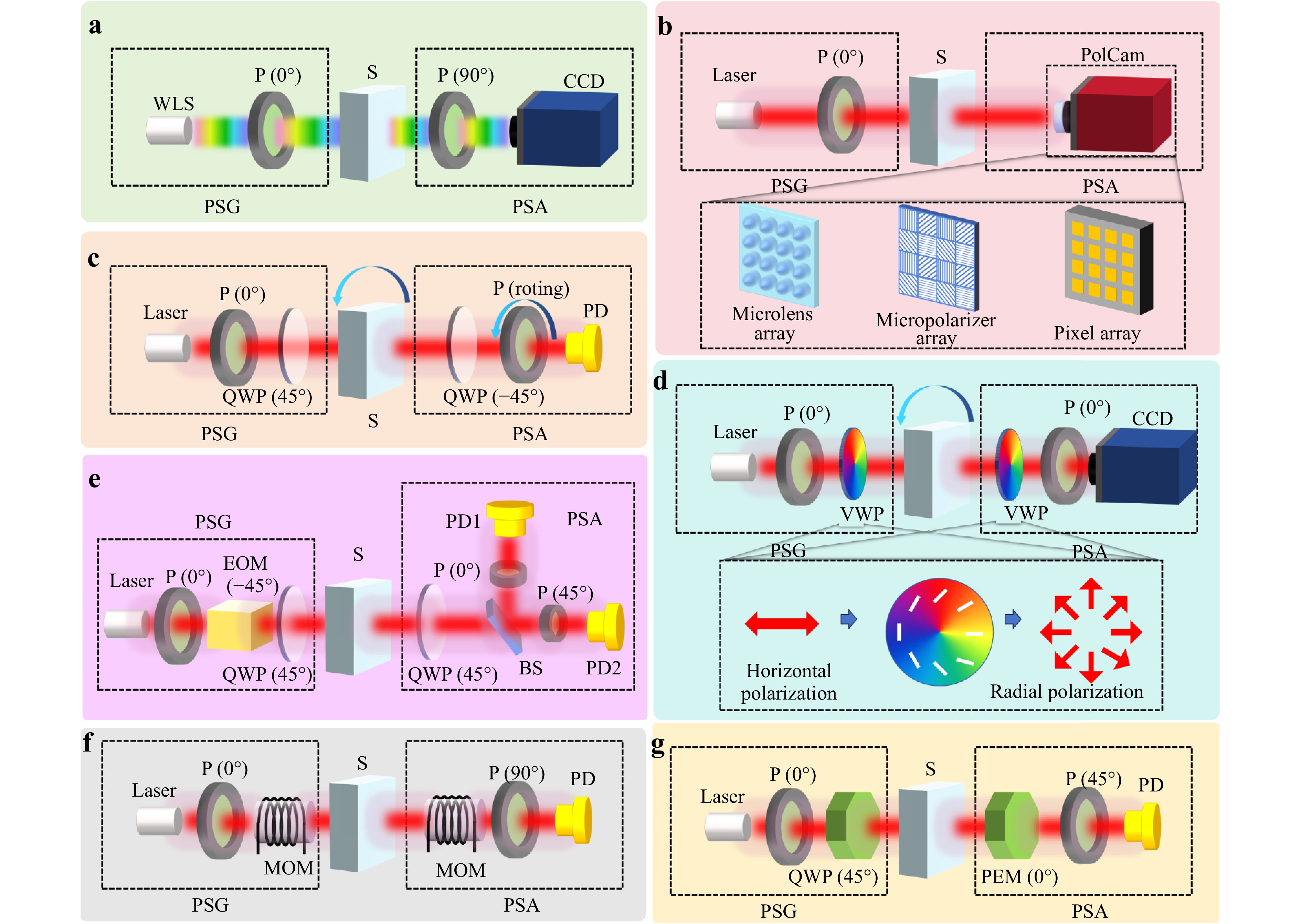
Fig. 5 Typical polarimetric modulation analysis technologies. Simple polarimeter with orthogonal polarizers55 a and polarization camera57 b. Birefringence measurement system modulated by waveplate c, VWP58 d, EOM59 e, MOM60 f and PEM61 g. The abbreviations of the components in the systems above are as follows: Polarization State Generator (PSG); Polarization State Analyzer (PSA); sample (S); polarize (P); quarter-wave plate (QWP); vortex waveplate (VWP); electro-optic modulator (EOM); photoelastic modulator (PEM); magneto-optic modulator (MOM); beam splitter (BS); photodiode (PD); charge-coupled-device camera (CCD); polarization camera (PolCam); white-light source (WLS).
Driven by advances in precision manufacturing and emerging polarimetric devices, polarization cameras are gaining a central role; they simplify optical detection, and can be broadly categorized into division-of-time66,67, division-of-amplitude68, division-of-aperture69,70, and division-of-focal-plane71,72 architectures, with recent developments further incorporating metasurface-based spatially multiplexed designs for compact and snapshot polarimetric imaging73. Lane et al.57 implemented birefringence distribution measurements using a polarisation camera (Fig. 5b). The polarisation camera provides four polarisation analysis channels at 0°, 45°, 90°, and 135°, enabling simultaneous measurements of the corresponding linear polarisation components. Because it cannot cover all angles, the external polarisers are rotated multiple times to gather data for a set of Stokes parameters. The fitting algorithm matches these data to a theoretical model to determine the phase retardance, axis orientation, degree of polarisation, and other parameters. The polarisation camera based on the microlinear polariser array can simultaneously measure only the first three Stokes parameters (S0−S2), but not the circular component S3; therefore, it cannot directly acquire the complete parameters in a single snapshot. By introducing controllable polarisation modulators, this limitation can be effectively overcome by encoding the information of all the Stokes components, including S3, into the measured S0–S2 signals. For example, Wang et al.74 demonstrated that by acquiring a set of input–output Stokes measurements, the complete Mueller matrix of the sample can be reconstructed using only six modulation states, implemented with a polarisation camera combined with dual rotating retarders. A more compact solution is provided by LC-based polarization cameras. Ye et al.75 demonstrated an electrically regulated polarimetric camera based on a single twisted nematic LC chip in which electrically tunable LC elements were integrated directly in front of a CMOS sensor and rapidly switched by voltage control to realise solid-state polarisation modulation without any moving parts. An alternative solution for accessing the circular polarization component S3 is to employ planar nanostructured polarisation analysers that spatially multiplex multiple polarisation projections onto a single sensor, thereby enabling snapshot full-Stokes measurements without temporal modulation. Belle et al.76 proposed a spatially resolved real-time polarimetric measurement method based on a hollow waveguide array. It uses a directional waveguide array with an analyser and CMOS camera to form the PSA. The hollow waveguide array introduces artificial birefringence by design, allowing direct measurement of the Stokes parameters (S0–S3) at a spatial resolution without moving parts. It achieves 50 µm2 resolution and fast, real-time polarisation measurement. With no moving parts or single-shot measurements, the proposed system is compact and efficient for precise optical applications. Metasurface-based full-Stokes polarisation cameras have recently emerged as an important method for ultracompact and integrated polarization sensing77,78. By engineering subwavelength anisotropic and chiral meta-atoms, metasurfaces can directly map different polarisation components to independent spatial, spectral, or intensity channels, enabling the single-shot acquisition of all four Stokes parameters without mechanical scanning or temporal modulation. Organic semiconductors79,80, metal-halide perovskites81,82, and two-dimensional materials83,84 can be directly employed as active materials for fabricating polarisation-sensitive photodetectors and cameras. The integration of metasurface polarisation control elements with these novel photodetector platforms offers a promising pathway toward compact, alignment-free, and highly integrated polarimetric imaging systems for quantitative linear birefringence measurements in on-chip and high-speed applications.
Waveplate modulation methods offer greater freedom of modulation, improved measurement accuracy, and applicability. A single wave plate or a combination of wave plates can more precisely control light polarisation and directly measure sample birefringence via intensity changes under different polarisation states. Waveplate modulation methods employ various implementations and measurement principles. The Tardy quantitative method (Fig. 5c) uses a laser to reduce the dispersion effects and requires the retardance axis of the sample to be parallel to the polariser axis. The sample must be rotated around the surface normal, and the analyser is turned to minimum intensity. The phase retardance is then calculated from the precise quantitative relationship between the retardance-axis orientation of the sample and the analyser’s rotation angle. Although this method accounts for the orientation of the retardance axis and improves the accuracy, it is cumbersome and unsuitable for rapid measurements. Wu et al.85 proposed a high-speed spatiotemporal birefringence measurement method. Unlike Tardy, the first QWP rotates at high speed, and the CCD is a 10 kHz camera, which captures the axis orientation and retardance changes under load. Its core feature is a sequential analysis method that uses multiple-intensity images to rapidly build a spatiotemporal birefringence map, which delivers high-precision real-time data under dynamic loads and serves as an effective tool for tissue and failure analysis. Pretka et al.86 analysed the sensitivity of small dynamic retardance measurements. The PSG of the system comprises a polariser and Wollaston compensator, whereas the PSA consists of a QWP, polariser, and CCD. By matching the dynamic retardance-axis orientation to a system-dependent reference orientation and precisely adjusting the azimuth of each optical element, the system maximises the fringe-phase contrast, allowing the precise measurement of phase-delay changes by analysing fringe shifts. The experiments show 6000× sensitivity gain and 0.003° accuracy. Despite the sensitivity boost, it attains a peak sensitivity over a very limited range and is extremely cumbersome, limiting its practical use. Moreover, studies indicate that polarisation optic demodulation for birefringence measurement is generally nonlinear, causing the sensitivity to vary nonlinearly across the measurement range. Lin et al.87 used a Zeeman laser to generate dual-frequency orthogonal beams, and proposed a novel birefringence method. Under an applied magnetic field, the atomic energy levels in the laser medium split according to the Zeeman laser principle. The system comprises a Zeeman laser, HWP, QWP, sample, QWP, polariser, and PD. It measures birefringence distributions in PEN films etc. by scanning, with standard deviations of axis orientation and phase retardance errors of ≤0.20° and ≤0.52°, respectively. Zeeman lasers are less stable than single-frequency lasers. Field stability directly affects the laser output frequency and measurement results. In environments with large field fluctuations, the measurement stability may suffer. In addition to conventional uniform waveplates, novel spatial light polarisation control plates, such as DOE waveplates, have recently attracted wide interest. They provide more control freedom, uniquely modulating the beam polarisation, and offering an efficient measurement tool for more complex optics. The most representative is the zero-order VWP, an optical element combining standard half-wave behaviour with vortex‐beam characteristics. VWP (Fig. 5d) achieves a 180° phase delay and, by introducing a helical phase, maintains a constant phase retardance across the aperture, while its fast axis continuously rotates, thus generating radial polarisation. Chen et al.88 proposed a new measurement method using the VWP. After passing through the test plate, the polarisation state of the beam changes, affecting its intensity distribution. In this method, the test plate is rotated to capture two distinct intensity-change patterns. Rotation alters the relative orientation to ensure full interaction between different polarisation states. The results show measurement errors of approximately 0.087° for the phase retardance and 0.094° for the fast axis angle, demonstrating high precision and feasibility. Zhu et al.58 improved upon this using radial polarisation and analysers in both stages (Fig. 5d), and achieved single-shot measurements with no mechanics involved. Unlike traditional methods, they introduced a Fourier analysis instead of conventional mean intensity calculations to effectively avoid source fluctuation effects. This method not only achieves stable phase retardance measurements (standard deviation < 0.3°) but also high-precision fast-axis angle measurements (average absolute error < 0.04°).
Another strategy for achieving high-precision and efficient birefringence measurements is to introduce dynamic birefringent-device modulation. Dynamic modulation not only provides real-time monitoring of a sample’s birefringent characteristics but also effectively enhances the measurement sensitivity and accuracy. The aforementioned birefringence measurement methods often rely on static polarisers or waveplates, adjusting the light polarisation by rotating the waveplate or polariser. These have limitations such as system complexity, cumbersome operation, and a strong dependence on rotation angles. Dynamic birefringent device modulation introduces tunable optical elements such as EO, MO, and PEM modulators, enabling real-time polarisation control without the physical rotation of components, thereby precisely controlling the beam’s polarisation and phase without moving the optical systems. These methods render birefringence measurements more flexible, faster, and adaptable to various experimental requirements. Lo et al.59 (Fig. 5e) used an EOM with sinusoidal modulation and processed signals via Fourier-Bessel expansion, simultaneously measuring the retardance-axis orientation and phase retardance in linear birefringent materials. System errors mainly originate from the misalignment of the electro-optic modulator and defects in the optical components, especially the misalignment of the EOM, which causes significant errors. However, the system showed good repeatability, with an average error of 0.186° for the axis angle and 0.356° for the phase retardance. Li et al.60 (Fig. 5f) proposed a high-precision glass internal stress measurement method using the MOM. By combining two independent MOMs to adjust the polarisation states, the birefringence induced by glass stress is obtained, and the system maintains high stability under environmental changes, offers strong adaptability, and effectively enhances the signal amplitude while reducing noise interference. The experiments showed a precision of 0.3 nm/cm. However, owing to the small Verdet constant of magneto-optic materials, even under strong magnetic fields, the Faraday rotation angle produced is limited, resulting in an insufficient polarisation modulation amplitude. The analyser-converted intensity after modulation varies quadratically with the rotation angle, rendering the fundamental component extremely small. This makes signal demodulation difficult, results in high dispersion, and because a small amplitude requires long integration and averaging to improve the signal-to-noise ratio (SNR), leading to lengthy measurements that limit practicality. The PEM method61,89 is a mainstream commercial solution for high-precision birefringence measurements. Using high-frequency polarisation modulation of the PEM, the detected signal carries both the PEM modulation frequency and birefringence information of the sample (Fig. 5g). Using the DC, fundamental and second harmonic components, phase retardance, and axis orientation are simultaneously solved, achieving rapid online calibration measurement of phase retardance and fast-axis orientation in the same path, with a single-point measurement time of 20 ms, phase delay resolution < 0.043 nm, and relative error < 0.71%.
In a broad range of situations, the polarisation response of a sample may involve not only linear birefringence but also dichroism, circular anisotropy, and depolarisation. Mueller matrix measurements based on a polarimetric modulation-analysis framework have recently attracted increasing attention for achieving complete characterisation of the polarisation properties. This is achieved at the expense of increased system complexity compared with methods specifically designed for linear birefringence measurement. Linear birefringence measurement can be regarded as a particular case within the Mueller matrix measurement. The conventional Mueller matrix measurement system90 employs wave plates and linear polarisers such as PSG and PSA to generate and analyse a more diverse and complex set of polarisation states than approaches limited to linear birefringence. In principle, at least 16 intensity images corresponding to independent PSG-PSA state combinations are required to reconstruct the complete 4 × 4 Mueller matrix. This approach provides complete and quantitative polarimetric information. However, it relies on multi-frame sequential acquisition and mechanically rotated components, which lead to limited temporal resolution and increased sensitivity to sample motion and system drift. Yu et al.91 employed a more sophisticated PSG capable of simultaneously generating a pair of complementary incident polarisation states within a single configuration, including 0°/90° and 45°/135° linear polarizations, and right-/left-circular polarisations. Using these three complementary pairs of incident polarisation states, the complete Mueller matrix can be reconstructed from only three acquisitions, significantly improving the measurement efficiency. Feng et al.92 reported an ultrafast method in which multiple polarisation projection states were spectrally encoded using a specially designed PSG-PSA architecture and subsequently converted into a single time-domain waveform through an optical time stretch, from which the Mueller matrix was reconstructed using a calibrated linear inversion model. This architecture enables single-shot, nanosecond-scale Mueller matrix measurements for dynamic processes; however, it assumes a wavelength-invariant Mueller matrix and relies on a complex single-point ultrafast system, limiting its applicability. Oh et al.93 realized an ultra-wide-field spectroscopic Mueller matrix imaging system in which both the polarisation state generator and analyser were implemented using dual rotating wire-grid polarisers, enabling pixel-wise reconstruction of the Mueller matrix spectra over a field of view of approximately 20 mm × 20 mm. This strategy delivers high-throughput, spatially resolved polarimetric and spectroscopic information, but relies exclusively on linear polarization modulation, restricting the measurement to a reduced 3 × 3 Mueller matrix, and the required multi-state and multi-wavelength acquisition further limits its suitability for dynamic measurements. With the rapid development of nanofabrication and lithography technologies for polarisation optics, Zaidi et al.94 proposed a compact single-shot system based on spatially multiplexed metasurfaces in which both PSA and PSG were implemented using metasurface optics that encode multiple polarisation projection channels into the different spatial regions of a single image, enabling complete Mueller matrix reconstruction from a single camera exposure. By shifting the polarisation modulation from the temporal to the spatial domain, this work establishes a fundamentally new instrumentation paradigm and demonstrates how metasurfaces introduce additional design freedom for polarisation systems, opening new opportunities for polarisation detection and sensing.
Table 1 compares the performance of the different modulators used in the aforementioned methods, which helps to quickly identify the strengths and weaknesses of each device in terms of mechanism, bandwidth, and modulation depth, and thus choose the solution that best meets the experimental requirements. Other polarimetric modulation analysis techniques95–97 exist that focus on innovations or improvements in polarisation modulation, polarisation analysis, and signal demodulation.
Device Modulation Type Actuation Mechanism Modulation Frequency Modulation Range Typical Materials Fixed Waveplate Static Birefringence Static − Any Birefringence Quartz, MgF2, polymer, mica Rotating HWP Dynamic retardance axis Mechanical Rotation <100 Hz Axis orientation 0–180° with time VWP Spatial retardance axis distribution Static − Axis orientation 0–90°with spatial azimuth fused silica, Liquid-crystal polymer EOM/ LCVR Dynamic phase retardance Electric field kHz–GHz/
DC-1kHzTypical retardance range 0–π rad LiNbO3, KTP, BBO/ Nematic liquid crystal PEM Dynamic phase retardance Piezo-driven stress ~20–100 kHz Typical retardance range −π/2–π/2 rad Fused silica, BK7 MOM Dynamic optical rotation Magnetic field <1 kHz Typical rotation range (<π/4) TGG, YIG Table 1. Comparison of Polarization Modulation Devices
-
Interferometric methods rely on the principle of optical interference to calculate birefringence by measuring the phase difference, intensity variations, and other characteristic features of the interference signal. Interferometer designs mainly include traditional interferometer configurations and novel self-mixing interferometer structures. Traditional interferometer configurations include but are not limited to Michelson, Mach–Zehnder, Sagnac, and Fizeau interferometers. Based on the Michelson interferometer, Del Hoyo et al.98,99 (Fig. 6a) split an incident beam into two orthogonal linear polarisations using a polariser. The mirror of one arm is slightly tilted to produce high-contrast interference fringes, the test waveplate is then inserted before recombination, and after passing through a 45° analyser, the fringes are recorded by a camera. As the wave plate rotates, the fringes shift laterally. The fringe displacements and rotation angles were repeatedly recorded throughout the full rotation of the wave plate, and the data were fitted to calculate the birefringence parameters. Polarisation-sensitive OCT (PS-OCT)103,107 is a low-coherence Michelson interferometer that uses a superluminescent diode (SLD) or swept-source (SS) laser as the light source. The beam is split into reference and sample arms, and the reflected or backscattered light is interferometrically detected (Fig. 6b). PS-OCT is widely used for quantitative birefringence measurements in semitransparent scattering samples (e.g. biological tissues and filled polymers)108,109. Unlike in conventional OCT, the returned light is first passed through a polarisation beam splitter into two orthogonal polarisation channels (commonly labelled S and P), which are then synchronously detected using a dual-channel detector to acquire low-coherence interference signals. The local phase retardance and orientation of the retardance axis were calculated by comparing the phases of the two channels at the same depth. However, because PS-OCT relies on detecting backscattered light, fully transparent, non-scattering materials produce no usable backscatter signals, rendering it incapable of internal tomography in such media. Therefore, transmission-mode optical methods are required to measure the birefringence in fully transparent media.
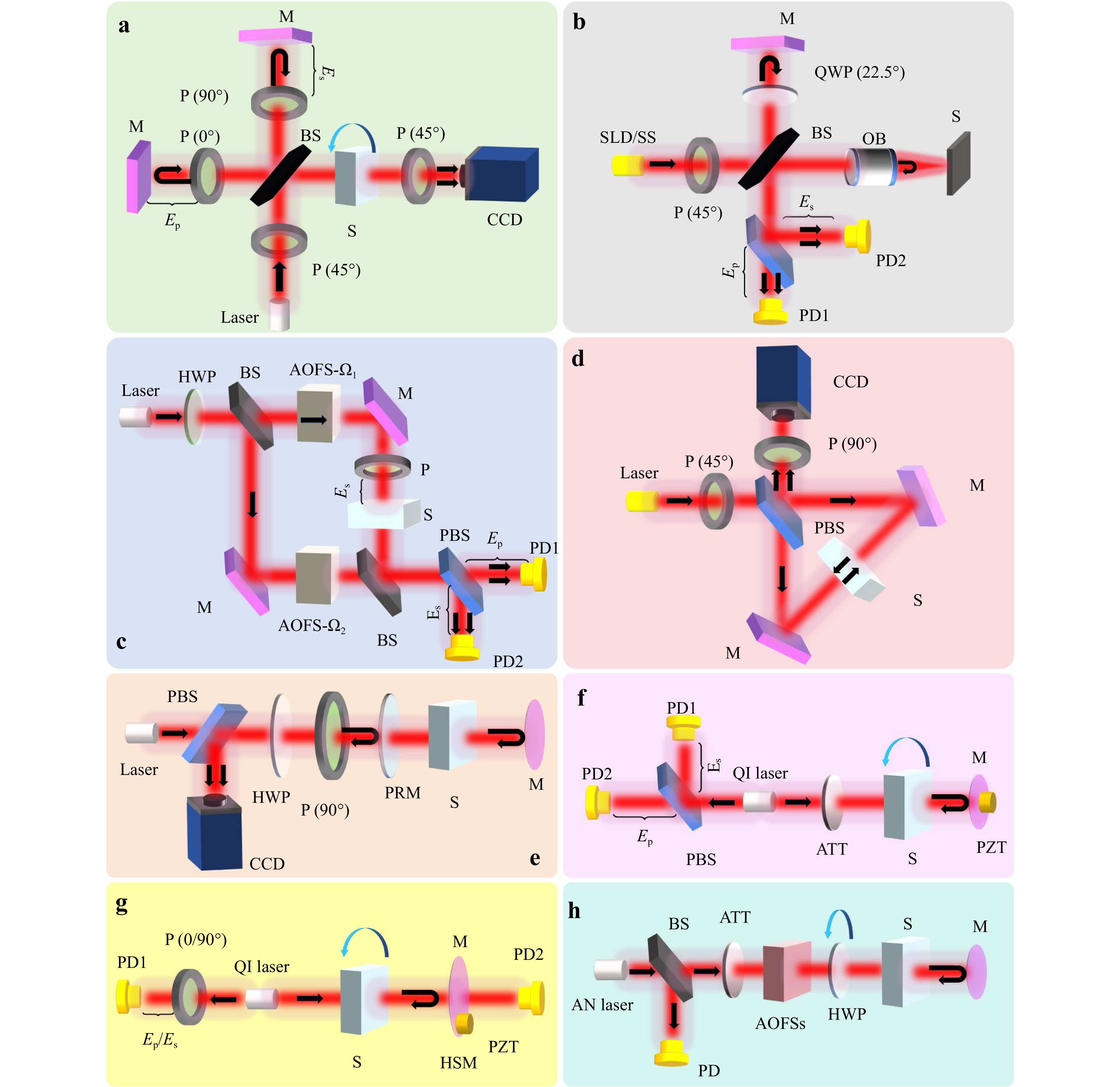
Fig. 6 Typical interferometric technologies. Birefringence measurement system based on Michelson interferometry98 a, b, Mach-Zehnder interferometry100 c, Sagnac interferometry101 d, Fizeau interferometry102 e and Self-Mixing interferometry f-h. b OCT103, essentially a reflection-mode low-coherence Michelson interferometer. Self-Mixing interference by the method of orthogonal phase difference104 f, polarization flipping105 g and amplitude-phase modulation106 h. The abbreviations of the components in the systems above are as follows: mirror (M); polarizing beam splitter (PBS); half-wave plate (HWP); objective (OB); superluminescent diode/swept-source laser (SLD/SS); acousto-optic frequency shifter (AOFS); shifted frequency (Ω); attenuator (ATT); piezoelectric transducer (PZT); quasi-isotropic (QI); anisotropic (AN); partially reflecting mirror (PRM); p- and s-polarized component (Ep/Es).
Compared to the Michelson interferometer configuration, the Mach-Zehnder interferometer spatially separates the reference and sample arms completely, facilitating the insertion of polarisation control elements or modulators into the sample arm without disturbing the polarisation state of the reference arm. Moreover, because the paths of the two arms are independent, an acousto-optic modulator (AOM) or EOM can be placed in each arm to achieve heterodyne interference or phase modulation, thereby enabling high-sensitivity lock-in detection and improving the measurement accuracy and dynamic range of the phase retardance. Lang et al.100 used a Mach-Zehnder interferometer based on heterodyne interference (Fig. 6c), in which two AOMs generated an approximately 60.32 kHz beat-frequency carrier while recording horizontal and vertical polarisation interference signals. They then used maximum likelihood estimation to extract the signal amplitude and phase and independently solved them in real time to determine the phase retardance and axis orientation of the LCVR, requiring no mechanical adjustment to suppress environmental disturbances and common-mode noise, thus providing key performance metrics for high-speed, wide-range birefringence characterisation. Wei et al.110 employed a fibre-based Mach-Zehnder interferometer combined with MEMS micromirror scanning, which achieved large-aperture, non-contact, and full-surface stress measurements. A 1,550 nm distributed feedback laser source was passed through an AOM to generate an 80 MHz frequency-shifted beam that interfered with the test beam. The polarisation beam splitter recorded the intermediate-frequency signals of the horizontal and vertical components, which were demodulated using a digital signal processing system using the phase difference between the two heterodyne signals. Thus, the optical path delay of the sample was directly obtained, allowing the stress value of the sample to be calculated. The system’s phase detection accuracy reached 5 × 10⁻⁵ rad. For a 2 mm-thick fused quartz sample, the stress measurement accuracy reached 1.8 kPa with a relative error of less than 0.01%, meeting the requirements for high-speed, wide-range, high-precision stress characterisation.
Certain specialised interferometer configurations demonstrate advantages in various application scenarios. Schnoor et al.101 implemented dynamic birefringent element measurements based on a Sagnac interferometer (Fig. 6d). Using a common-path interferometer built with a pair of polarisation beam splitters and symmetrical mirrors, the LCVR sample produced a phase difference between two counter-propagating beams. The phase retardance was inverted from the lateral displacement of the interference fringes recorded by the camera. Compared with traditional crossed or co-polarizer methods, this approach effectively suppresses intensity of noise while directly applying FFT for fringe phase calculation and unwrapping to achieve real-time mapping between the phase retardance δ of the LCVR and the drive voltage V, thereby characterising the key performance metrics of a high-speed, wide-range birefringence measurement system. Furthermore, the Sagnac interferometer has a ring common-path structure that inherently cancels environmental disturbances, vibrations, and thermal drifts. This scheme ensures high sensitivity and a wide dynamic range, while avoiding the complex path matching and mechanical adjustments required in the Michelson and Mach-Zehnder beam-splitting designs. It requires only one coupler and a segment of a polarisation-maintaining fibre for full fibre integration, thus giving it an irreplaceable advantage in fibre stress birefringence measurement111,112. Tan et al.102 introduced a polarisation-adjustable phase-shift principle with a rotatable polariser using a Fizeau interferometer (Fig. 6e). The Jones matrix model describes how phase-shift interferometry can be achieved by inserting a linear polariser in a common optical path and rotating it to 0°, 45°, 90°, and 135°. The residual birefringent phase retardance and the orientation of the retardance-axis at each pixel can be directly determined by combining and differentiating the four phase-shift results without the noncommon-path matching required by the Mach-Zehnder design. In testing large-aperture optical elements having a 230 mm diameter aperture, this method achieved a peak-valley (PV) repeatability of 0.1 nm/cm (standard deviation 0.029 nm/cm), and a spatial resolution at sub-millimeter scale. Compared to traditional commercial polarimeters, the test time was reduced from over half an hour to a few minutes, greatly enhancing the rapid, high-precision detection of residual birefringence in large-aperture optical materials.
Traditional interferometry demands reference–measurement interactions, yielding high complexity. As a special configuration, self-mixing interferometry (SMI)113,114 treats the intracavity field of the laser as the reference beam, eliminating the need for an external reference arm and effectively reducing system complexity. Moreover, self-mixing exhibits a richer phenomenon than traditional interferometry. The feedback interaction with the intracavity field leads to a new dynamic balance in the amplitude, phase, frequency, and polarisation of the laser. Additionally, self-mixing integrates the source and detector, and the intracavity field serves as a reference and amplifies the interaction with feedback with a gain of up to 106, leading to a simple optical path, easy collimation, and high sensitivity115. Polarisation effects in SMI involve three key phenomena: orthogonal component phase difference116, polarisation flipping117, and amplitude–phase modulation118,119. The first two effects apply to quasi-isotropic lasers, whereas the latter applies to anisotropic lasers. Quasi-isotropic lasers, such as Nd:YAG, He–Ne, and VCSELs, have isotropic gain media, but the complex output polarisation is affected by intracavity stress, external forces, pump power, and pump polarization120,121. The addition of feedback introduces complex dynamics. The residual random stress induces a slight anisotropy in the refractive index of the laser crystal, causing frequency splitting into two orthogonal polarisation modes. Mode competition favours the polarisation closest to the gain peak, resulting in a well-defined polarisation state. Consequently, at low pump levels, quasi-isotropic lasers emit single-mode linear polarisation in arbitrary orientations. However, feedback can readily shift the competition balance and alter the output polarisation. The orthogonal component phase-difference method104 (Fig. 6f) uses a polarisation beam splitter with its decomposition axes at 45° to the initial polarisation of the laser; the two orthogonal outputs are detected separately. With the birefringent sample in the external cavity, the laser output shifts from linear to a slightly elliptical polarisation, generating a fringe phase difference. With the PZT-driven mirror motion, the phase difference peaks when the retardance axes align. The birefringence was calculated as the ratio of the maximum phase difference to the sample retardance and alignment angle. This method is simple and accurate, but requires sample rotation, making it complex and unsuitable for spatially varying birefringence. The polarisation flipping method105 (Fig. 6g) adopted at higher feedback levels than the phase difference method. When the retarder axis is parallel or perpendicular to the initial polarisation of the laser, the sample induces a flipping point in the fringes. The output shifts from a single linear mode to alternating dual-orthogonal modes. This is because the effective reflectivities of both the polarisation modes are modulated. The mode with higher reflectivity experiences lower cavity losses and thus preferentially reaches the lasing threshold. The flipping region peaks when the sample retardance axis aligns with the initial polarisation. The birefringence was obtained from the duty cycle of the flipping region. This method is simple and accurate; however, its measurement procedure is complex.
Later studies found that these two effects also depend on both external birefringence and intracavity stress122. Intracavity stress is difficult to control precisely, meaning that lasers with varying internal stresses exhibit different feedback behaviours, reducing measurement accuracy and increasing unpredictability and instability. In contrast, anisotropic lasers have inherently anisotropic gain media, exhibiting significant differences in output characteristics and feedback effects compared with quasi-isotropic lasers. For example, in Nd:YVO4 lasers, the gain spectrum is polarisation-dependent: the π-polarised emission (parallel to the crystal axis) is much stronger than the σ-polarised. The large difference in gain ensures that the π mode always prevails, yielding stable π-polarised output conducive to the controlled measurements. With optical feedback, the Nd:YVO4 laser maintains a linear polarisation output, avoiding the polarisation instabilities observed in quasi-isotropic lasers and enabling stable and controllable operation. A birefringence measurement method based on Nd:YVO4 feedback polarization106 (Fig. 6h) uses frequency-shift modulation to move the detection signal to 2 MHz, avoiding low-frequency noise. Polarisation modulation using a rotating half-wave plate replaces the sample rotation, reduces complexity, and enables multifunctional measurements of static, dynamic, and spatial birefringence. Results show standard deviations of 0.0453° in phase retardance and 0.0939° in axis orientation, with sample transmittance down to ~10−5.
These interferometric methods reviewed above mainly aim to quantify linear birefringence parameters such as phase retardance and retardance-axis orientation, and are therefore well-suited for characterising the principal anisotropy of transparent media. Similarly, to achieve a complete characterisation of the coherent polarisation transfer properties, holographic interferometric approaches123 also enable full Jones matrix measurements, in which linear birefringence is naturally included as a particular case. In general, the full Jones matrix can be obtained by the object wave interfering with polarisation-orthogonal reference waves and reconstructing the complex vectorial optical field from a multiplexed hologram, from which the complete complex Jones matrix is directly retrieved by relating the recovered orthogonal field components to the known incident polarisation states. Li et al.124 proposed a single-shot, dual-wavelength, and polarisation-multiplexed scheme based on Kramers-Kronig (KK) holographic multiplexing, in a modified Mach-Zehnder interferometer, in which partial spectral overlap enabled significantly improved spatial bandwidth utilisation while ensuring the retrieval of the full complex Jones matrix. Owing to its noniterative reconstruction and single-shot acquisition, real-time Jones matrix imaging at video rate (30 fps) is demonstrated, making this technique particularly attractive for the dynamic birefringent samples. Qiu et al.125 introduced a single-shot off-axis polarisation holographic Jones matrix measurement method assisted by KK relations, where the polarisation-resolved holograms are simultaneously recorded by a polarisation camera, and analytic-signal reconstruction is used to remove the autocorrelation terms, leading to a markedly enlarged usable spatial bandwidth and an approximately 2.12× improvement in resolution while maintaining real-time capability. Liu et al.126 proposed a single-shot common-path polarisation holographic scheme with partially coherent illumination, in which two mutually orthogonal polarisation states simultaneously illuminate the sample, and polarisation- and angle-multiplexed holograms are generated and recorded in a common-path configuration to reconstruct the full complex Jones matrix. The system exhibits improved phase stability and effective suppression of speckle and parasitic interference; however, its reliance on Fourier-plane spatial filtering and dual-camera acquisition increases the system complexity and calibration demands. Liu et al.127 presented a compact single-shot Jones matrix imaging system based on polarisation in-line holographic microscopy, in which two orthogonal illumination states (±45°) are generated simultaneously and a polarisation beam displacer maps the four polarisation-resolved in-line holograms onto different regions of a single CCD, forming a fully common-path and highly compact optical layout without a separate reference arm, enabling complex-field reconstruction and subsequent synthesis of the full Jones matrix within one exposure. These single-shot Jones matrix measurements enabled the observation of transient anisotropy and rapidly evolving polarisation dynamics. In practice, the achievable temporal resolution is primarily limited by the camera frame rate and exposure time, together with the computational cost of complex-field reconstruction and matrix retrieval, particularly when iterative holographic phase retrieval or twin image suppression is required.
To provide a systematic overview of the differences in the structural complexity and measurement capabilities of the different interferometric configurations, Table 2 summarises five representative designs—Michelson, Mach-Zehnder, Sagnac, Fizeau and Self-Mixing—highlighting their reference/measurement arm arrangements, support for transmission and reflection modes, heterodyne or lock-in detection capabilities, and other key characteristics. This comparative summary allows researchers to quickly grasp the strengths and limitations of each architecture and select the most appropriate interferometer for a given application.
Interferometric Structure Structural Complexity Characteristics Michelson Medium Separated reference/measurement arm; transmission-mode measurement (except OCT in reflection mode). Mach-Zehnder High Separated reference/measurement arm; transmission-mode measurement; heterodyne configuration Support. Sagnac Relatively High Loop configuration with counter-propagating beams; bidirectional transmission-mode Measurement; excellent noise immunity. Fizeau Relatively Low Partially common-path reference/measurement arms; transmission/ reflection-mode measurement Self-Mixing Low No separate reference arm (intracavity reference); transmission-mode measurement; heterodyne configuration Support. Table 2. Comparison of Interferometric Structures for Birefringence Measurement
-
In addition to polarisation modulation analysis and interferometry, a distinctly different class of polarisation optical birefringence measurement techniques exists. One example is a method that exploits the system’s own physical effects for birefringence measurement, such as the frequency-splitting method128,129. In this method, a birefringent element (e.g. wave plate or sample) is placed inside a linearly polarised laser cavity. A small birefringence causes a slight difference in the refractive indices between the horizontal and vertical eigenmodes, leading to the splitting of their resonance frequencies. By capturing the beat signal of the two modes using a high-speed photodetector and an RF spectrum analyser, one can measure the frequency difference Δf precisely. Then, using Δφ = 2πΔf·L/c (where L is the effective intracavity path length and c is the speed of light), the phase retardance Δφ is computed to quantify birefringence. This method has a simple setup and is inherently robust against vibrations and temperature drift. Its measurement range spans 0–π, resolution reaches the 10−3 rad level, and experimental uncertainty is below 0.0036 rad.
Another representative approach uses computational imaging algorithms to probe birefringence130,131. For example, Zhang et al.132 proposed a birefringence measurement method that combines PIE, which enhances precision by introducing a diffractive element. In this method, a rotating polariser changes the polarisation state and diffraction patterns are recorded at different polariser angles. Diffraction is analysed using PIE to reconstruct the phase and amplitude. The advantage of this method is its ability to provide high-precision quantitative results for complex materials, particularly those that traditional methods struggle to handle, such as opaque or structurally intricate samples. Park et al.133 proposed a synthetic-aperture-based Jones matrix synthesis algorithm in which multiple Jones matrices acquired under different illumination angles are coherently combined in the complex domain to substantially suppress the coherent phase noise and enhance the polarisation sensitivity of weakly birefringent samples. This approach enables high-sensitivity Jones matrix imaging of living eukaryotic cells, benefiting from the strong noise suppression and physically transparent, non-iterative processing based on direct field synthesis and eigen-analysis, at the expense of reduced temporal resolution and increased stability requirements because of the need for multi-angle and multi-frame acquisitions. Dai et al.134 introduced a vectorial Fourier ptychography algorithm to reconstruct complex-valued Jones matrices over a large field of view and beyond the diffraction limit, with the additional capability of jointly correcting polarisation-dependent system aberrations. While this method enables complete and physically consistent Jones matrix reconstruction with high spatial resolution, its iterative Gauss-Newton optimisation and joint system–sample estimation lead to a relatively high computational cost.
-
Transparent and translucent materials play vital roles in everyday life, modern industrial manufacturing, aerospace technology, and contemporary scientific research. This section systematically examines the demand for birefringence measurements across four domains: stress analysis, materials science, biomedical applications, and the characterisation of novel polarisation-optical components.
-
Internal stresses from post-processing annealing or external forces during installation often induce anisotropic stress and orientation, altering the local density and converting an originally isotropic medium into an anisotropic one, thereby causing stress birefringence135,136. Polarisation optical methods serve as classic tools for analysing the stress distribution and orientation by visualising stress via birefringence. Typically, the birefringent optical path difference per unit thickness is used to express stress magnitude, satisfying OPD = δλ/2πd, where δ is the phase retardance, λ is the probe laser wavelength and d is the material thickness. The magnitude of the phase retardance is proportional to the principal stress, and the retardance axis indicates the direction of the principal stress.
Kovács et al.137 (Fig. 7a) performed in-situ shear stress imaging on 300 mm single-crystal silicon wafers. The fixture load sites exhibited clear stress concentration, reflecting a direct load response. Meanwhile, the maps revealed significant stress anomalies at the internal defects under loading. The stress maps clearly reveal edge stress gradients and identify minute defects, providing direct evidence for wafer defect screening, edge quality assessment, defect traceability, and coordinated optimisation with processes such as ion implantation and annealing, thereby contributing to yield improvement and shortening production adjustment cycles. Vargas-Isaza et al.138 (Fig. 7b) conducted a study on thermoplastic injection-moulded parts and systematically evaluated the distribution of residual stresses under different moulding conditions and their effects on mechanical performance. The residual stress in these parts was predominantly flow-induced, with peaks ranging from 4.29 to 5.69 MPa—well below the flexural failure stress. Raising the mould temperature (80 °C) and packing pressure increased the part density and flexural strength but also elevated the residual stress, whereas the longer packing times slightly reduced it. These results offer quantitative guidance for the quality control, process optimisation, and service life assessment of high-precision transparent optical components. Wang et al.139 (Fig. 7c) focused on a rapid qualitative evaluation method for the residual stress in injection-moulded polycarbonate goggles. By extracting the average gray values from specific regions of the goggle lenses or along selected sampling lines and combining experimental testing with analytical evaluation, a correlation was established between the residual stress distribution and warpage deformation. Through the optimisation of process parameters—including mould temperature, melt temperature, injection speed, packing time, and cooling time—the maximum residual stress in the lenses was reduced by 59.7% to 4.874 MPa, and warpage deformation was reduced by 74.2% to 0.18 mm, significantly improving the moulding quality and dimensional stability of the product. This provides an efficient and practical approach to defect control and process optimisation of transparent polymer optical components. Moreover, birefringence stress measurements hold significant value for stress evaluation and control in glass products (particularly transparent structural components for aerospace)140,141, semiconductor products (such as photovoltaic modules142 and thin films143), and precision optical elements144. In stress testing, birefringence measurements are key for assessing the internal stress, orientation, and anisotropic defects. On the one hand, it supports research, development, and failure analysis, for example, mapping stress to identify structural weak points; on the other hand, it has entered production lines for quality control, such as online inspection of plastic optics and monitoring high-performance composite manufacturing. As the demand for precision fabrication increases, birefringence analysis plays a larger role in stress evaluation.
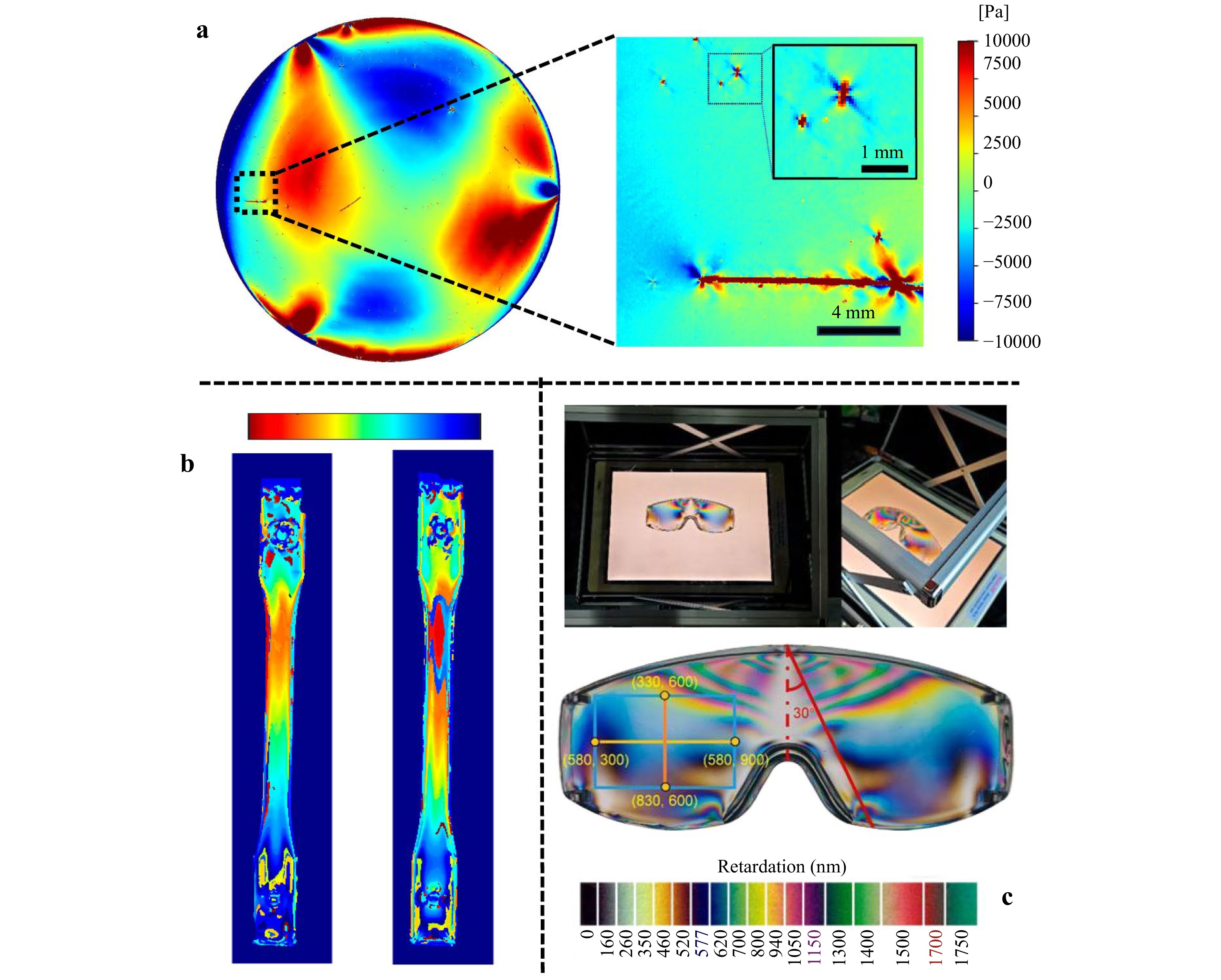
Fig. 7 Residual stress analysis. a Shear stress distribution of silicon wafer137, where the colour map represents the spatial distribution of the in-plane shear stress and the inset highlights the localized stress concentrations. Reproduced under CC BY-NC-ND 4.0. Copyright 2024, Elsevier. b Distribution of residual stresses in the injected part138, corresponding to two processing conditions. Reproduced under CC BY 4.0. Copyright 2023, MDPI. c Photoelastic images of the polycarbonate goggle139, showing the experimental setup, the stress distribution and the corresponding colour bar from top to bottom. Reproduced under CC BY-NC-ND 4.0. Copyright 2023, Frontiers Media.
-
Birefringence measurement is also a key method for revealing the optical anisotropy and structural tuning behaviour of crystalline materials145,146. It has not only become an important approach for assessing material structural integrity but also provides critical characterisation support for understanding structural evolution under various growth conditions, heat treatment states, and external field modulation, playing a significant role in high-quality crystal fabrication and material design optimisation.
Recently, 2D van der Waals materials have attracted attention owing to their layered structure and strong anisotropy, resulting in ultrahigh birefringence. Multiple studies have shown that these materials achieve refractive index differences far exceeding those of traditional crystals from the visible to infrared bands147,148. For example, As2S3 exhibits Δn ≈ 0.4 in the visible range149, and Ta2NiS5147 shows Δn ≈ 2.8 in the mid-infrared range (Fig. 8a), surpassing classical optical materials such as calcite and rutile. Extreme in-layer covalent/ionic versus interlayer van der Waals bonding causes high refractive index contrasts, yielding strong optical anisotropy. Additionally, some 2D materials feature non-centrosymmetric or bilayer modulations, boosting nonlinear birefringence152. In the above studies, birefringence measurements were required to retrieve the complex refractive index, enabling quantitative mapping of wavelength-dependent birefringence, while also serving as an important means to reveal the complex birefringence behaviour in anisotropic crystals. Oldenbourg150 imaged a uniform-thickness polycrystalline calcite film (Fig. 8b), encoding the optical axis azimuth in hue and the inclination angle in brightness, thereby obtaining a quantitative birefringence map over the entire field of view. Within individual crystalline domains, the hue and brightness were highly consistent, indicating uniform birefringence properties, whereas abrupt changes at the grain boundaries reflected discontinuities in the c-axis orientation. Bouhy et al.153 reconstructed the retardance and optical-axis orientation distribution of a composite geological thin section from sparse measurement data, thereby significantly reducing the measurement time while preserving the grain-level spatial resolution. Cao et al.154 used birefringence measurements to sort micron-sized crystals precisely. At the wavelength of 546.1 nm, they systematically examined birefringence of Al2O3, SiO2, KDP, LBO, and BBO samples with different sizes. Birefringence measurement is not only valuable for studying heterogeneous and topologically complex crystalline materials but also constitutes a critical analytical technique for investigating emerging materials. Ge et al.151 investigated the birefringence of lyotropic liquid crystals in microfluidic channels, acquiring the retardance and orientation angle distributions in real time at speeds up to 506 fps (Fig. 8c), thereby revealing structural formation and evolution during flow. By tracking the low-retardance regions, this technique quantitatively captures the local structural changes and dynamic features under steady-state flow, providing direct and precise experimental evidence for understanding the flow behaviour and orientational response of lyotropic liquid crystals. Overall, birefringence measurements play an important role in the quantitative characterisation and validation of research into novel materials. The analysis of the polarisation responses assesses the achieved anisotropy and guides structural and performance optimisation. With the emergence of new anisotropic materials, birefringence parameters have become key metrics for evaluating the performance of photonic functional materials and for geological mineral analysis.
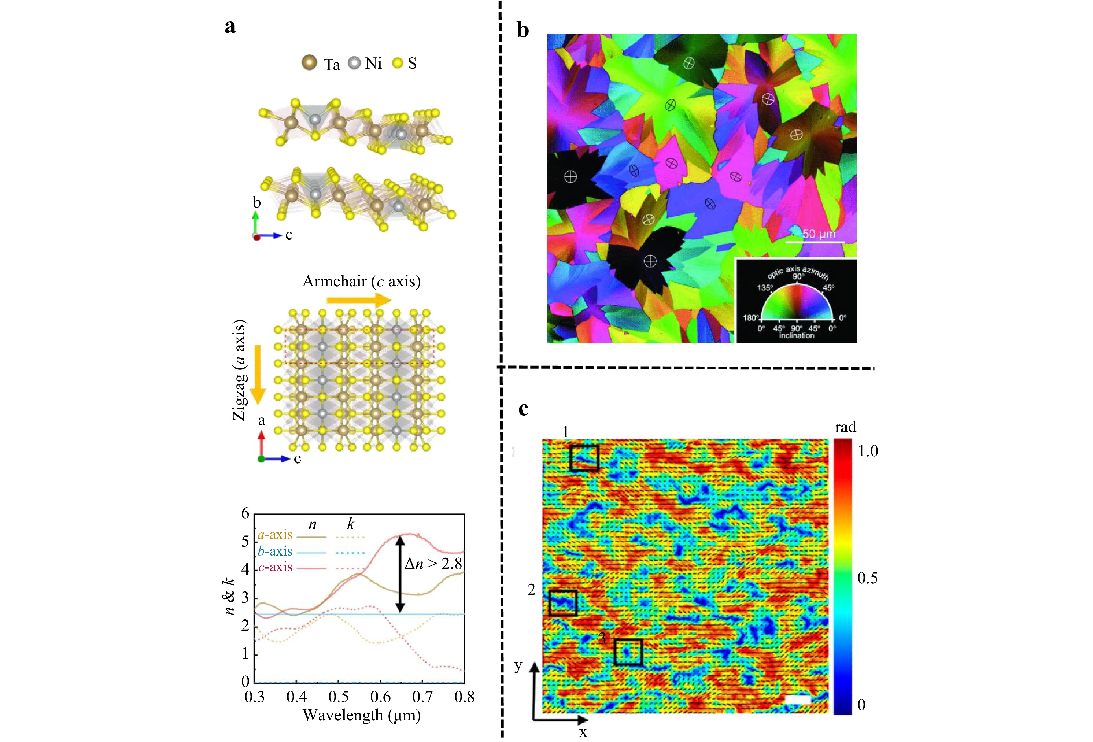
Fig. 8 Material characterization. a Structure and refractive-index values of Ta2NiS5 crystal147, showing the principal refractive indices along different crystallographic axes and the pronounced in-plane optical anisotropy. Reproduced under CC BY 4.0. Copyright 2023, Springer Nature. b Image of a thin polycrystalline calcite film of uniform thickness150, where the colour contrast reveals the spatial distribution of the crystal orientations and local optical anisotropy among individual grains. Reproduced with permission. Copyright 2008, John Wiley & Sons. c Retardance and orientation angle maps for a flowing liquid crystal151, showing the spatial distributions of birefringence. Reproduced with permission. Copyright 2021, American Chemical Society.
-
Biological tissues, either sectioned or within the superficial layer (typically 5–50 μm), exhibit good optical transparency, allowing light to penetrate and carry rich structural and molecular information. This localised transparency provides favourable conditions for birefringence measurement, making it an essential foundational tool for biological imaging, pathological diagnosis, and histological analysis.
Recently, birefringence measurements have shown unique advantages in tumour detection and pathology. Owing to its polarisation sensitivity, birefringence imaging reveals microstructural and anisotropic information that is inaccessible using conventional microscopy155 (Fig. 9a). Retardance axis orientation maps reveal changes in orientation within tissues, reflecting the ordered structure and remodelling the characteristics of collagen fibres, cell arrangements, and other features. Liu156 used quantitative imaging to study the birefringence distribution of the posterior sclera (Fig. 9b) and found that the posterior scleral birefringence (PSB) is closely related to the orientation and diameter of collagen fibres, which reflects changes in the tissue microstructure. PSB showed an increasing trend around the optic disc and posterior pole with higher degrees of myopia and could distinguish between patients with high myopia and those with pathological myopia, outperforming traditional indicators such as axial length. This study indicates that PSB can serve as a structural biomarker for early identification, monitoring, and prediction of myopia progression, providing new quantitative evidence for the timing of clinical intervention. Phase-retardance images provide quantitative information on the anisotropy strength and can sensitively capture optical anisotropy enhancements caused by variations in tissue density, fibre content, and abnormal growth. Different tumour types are significantly different from normal tissues in terms of their microstructure and optical anisotropy, leading to distinct changes in their birefringence properties. Birefringence measurement not only enables contrast-based differentiation between the normal and diseased regions but also assists in pathological grading and boundary determination. This approach has been successfully applied for the detection of various tumours, including skin cancer103 (Fig. 9c), breast cancer157, colorectal cancer158, and brain tumors159. In digital pathology and intraoperative diagnosis, birefringence images offer a non-haematoxylin and eosin (H&E) information dimension, complementing multimodal analysis. Moreover, Mueller matrix imaging160 can be used to obtain complete full-polarisation parameters (such as depolarisation, diattenuation, and birefringence characteristics), further enabling the multidimensional quantitative characterisation of the optical properties of tissues. In biomedical imaging, birefringence measurement provides label-free, intrinsic contrast without staining and is capable of revealing tissue microstructure and pathological changes. It is a powerful tool for early cancer screening and diagnosis, intraoperative guidance, and tissue engineering evaluation.
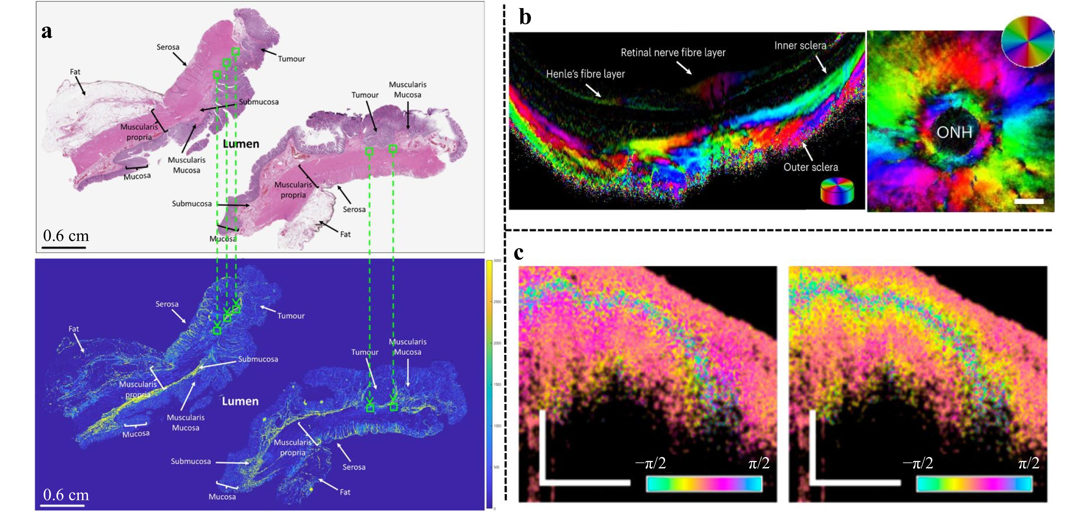
Fig. 9 Biological detection. a Comparison between H&E-stained histology image (top) and corresponding polarimetric intensity image (bottom)155. Reproduced under CC BY 4.0. Copyright 2022, Springer Nature. b The posterior sclera images by OCT156, including a depth-resolved image (left) and an en-face image (right). Reproduced under CC BY 4.0. Copyright 2023, Springer Nature. c Linear retardance maps of basal cell carcinoma along different polarization directions103. Reproduced under CC BY 4.0. Copyright 2017, MDPI.
-
Novel polarisation optical elements (e.g. LCVR, VWP, and birefringent metasurfaces) play a key role in precision optics and advanced photonic devices, and their performance directly determines a system’s polarisation-control capability and imaging/measurement accuracy. These elements often exhibit strong spatial anisotropies and complex structures, which increase the calibration requirements for accurate birefringence characterisation.
The LCVR features a wide dynamic range of birefringence, enabling rapid phase-retardance changes via the drive voltage (Fig. 10a). Although LCVRs offer large apertures, high control precision, and stable optical and chemical performances, the relationship between phase retardance and drive voltage is nonlinear and can exceed 2π, requiring precise calibration of the voltage-birefringence dynamic response before use101. The liquid crystal spatial light modulator (LC-SLM)161 is essentially a programmable array of LCVR which is capable of precisely encoding optical wavefronts and enabling dynamically tunable two-dimensional spatial birefringence distributions. It is widely used in high-precision optical systems such as wavefront control, holographic imaging, and polarisation modulation164. However, variations in the phase uniformity, nonlinear response, and thermal drift among different pixels under varying driving conditions can lead to degraded system performance or functional deviation if not accurately measured and calibrated. Therefore, quantitative phase retardance measurement of the SLM under actual operating conditions not only helps to determine its true dynamic phase modulation capability but also provides essential data for compensating pixel-to-pixel differences, optimising driving strategies, and improving wavefront control accuracy (Fig. 10b). Vortex retarders (VWP)162, made from birefringent liquid crystal polymers, generate higher-order beams such as vector polarisation and vortex beams. Structurally, an ideal VR provides a constant π/2 phase retardance across its aperture with a continuously rotating fast-axis orientation over the optical region; thus, uniformity of retardance and continuity of axis orientation reflect the quality of VWP fabrication (Fig. 10c). In recent years, metasurfaces have become a research focus in modern optics owing to their subwavelength-scale control of the phase, amplitude, and polarisation. Among these, anisotropic metasurfaces are the primary technological routes for realizing metasurface waveplates165. Compared to conventional crystalline waveplates, they are thinner, offer greater functionality, and enable programmable control. Numerous metasurface-based wave plates for wavelength, angle, and polarisation multiplexing, as well as optically and electrically triggered dynamic plates, have been reported51,166. The modulation performance of a birefringent metasurface fundamentally depends on the spatial accuracy of the phase retardance δ and axis orientation θ, as well as their spectral and angular dispersions (with wavelength and incidence angle). These devices comprise arrays of subwavelength anisotropic elements that impart different complex transmission/reflection coefficients to the polarisation components (Fig. 10d), thereby enabling pixel-level light-field control and achieving high-efficiency polarisation conversion, wavefront shaping, and holographic imaging. The corresponding birefringence detection requires multiple wavelengths, directional flexibility, and high-speed measurement. δ(x,y) and θ(x,y) should be quantitatively and traceably characterised under the target numerical aperture and field-of-view conditions, thereby closing the design-fabrication-verification-optimisation loop. Using birefringence measurements, spatially resolved imaging of the phase retardance distribution and axis orientation of these optical elements can be achieved, enabling a comprehensive evaluation of their polarisation-control performance, which is crucial for design optimisation and quality control.
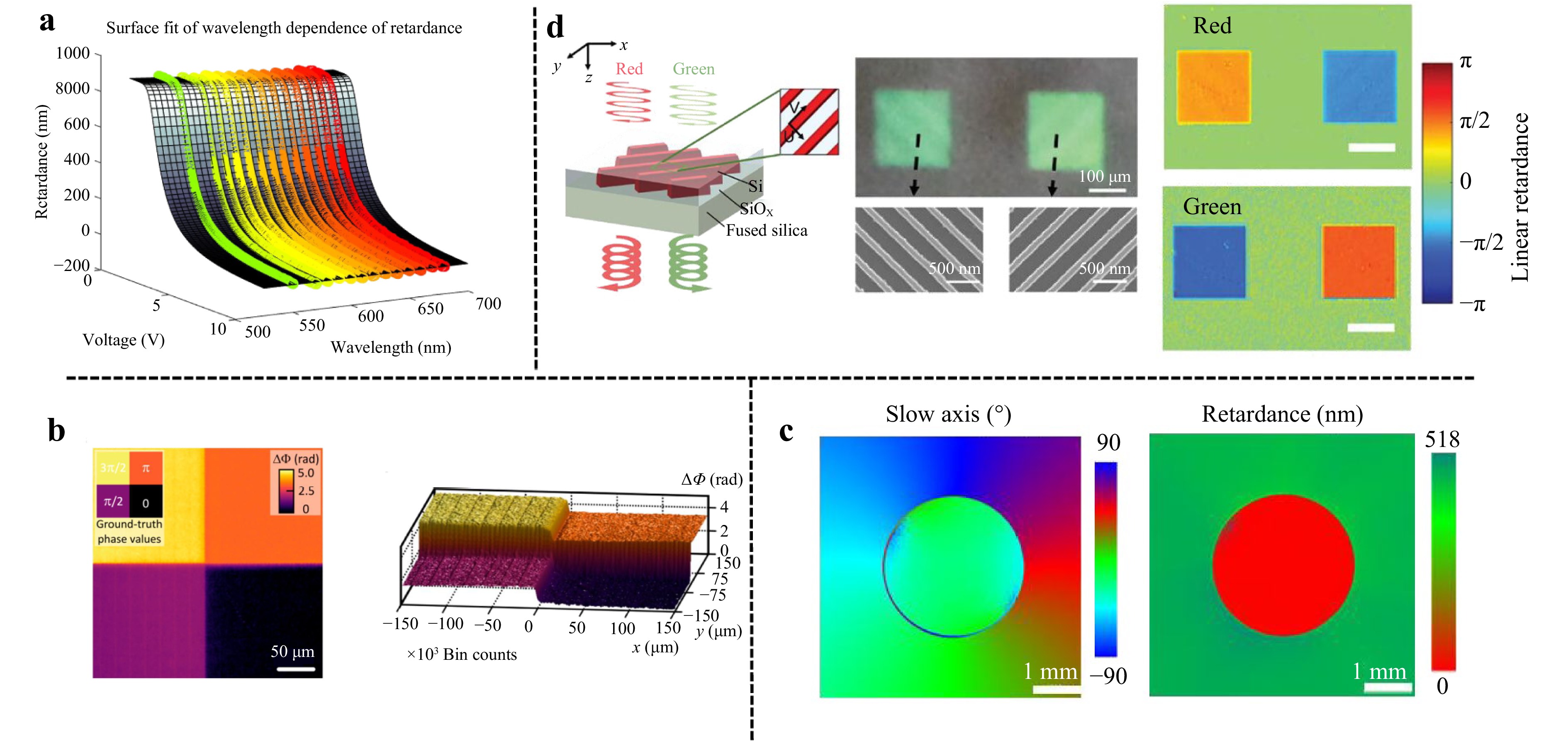
Fig. 10 Calibration of novel optical devices. a Phase retardance of the LCVR at different wavelengths101. Reproduced under CC BY 4.0. Copyright 2020, Optical Society of America. b Three-dimensional phase visualization of LC-SLM161, showing the loaded phase pattern on the LC-SLM (left) and the reconstructed phase distribution (right). Reproduced with permission. Copyright 2021, American Chemical Society. c Birefringence measurements of manufactured hollow S-waveplate 162, showing the spatial distributions of the slow-axis orientation (left) and the phase retardance (right). Reproduced under CC BY-NC-ND 4.0. Copyright 2022, Elsevier. d Si metasurface image163. From left to right, the panels show schematic illustration of the metasurface structure and functionality, optical microscope image (top) and SEM image (bottom), and linear retardance images under red (top) and green (bottom) illumination. Reproduced under CC BY 4.0. Copyright 2024, Wiley-VCH.
-
A systematic comparison of representative birefringence measurement methods is presented in Table 3. The comparison covers their measurement accuracy, technical characteristics, main limitations, and applicable scenarios. Conventional simple polarimetric approaches offer advantages such as low cost, straightforward implementation, and intuitive observation, but they are usually limited to qualitative analysis or low-precision measurements. In contrast, more advanced techniques can provide improved sensitivity or spatially resolved birefringence information. Therefore, the selection of an appropriate birefringence measurement method should consider the required accuracy, sample type, spatial resolution, and system complexity.
Method Accuracy Technical characteristics Limitations Applicable Range Ref δ θ Simple polarimeter (Colour Observation) ~200 nm − Low cost, simple system, and intuitive observation Neglect of retardance axis, only qualitative measurement, and need for rotating the sample to achieve better viewing Suitable for low-precision spatial and large birefringence, e.g., stress analysis, material/biological observation 55,56 Simple polarimeter (Laser-Based) std
0.48°
@632.8 nmstd
0.32°Low cost, simple system, and suppression of laser fluctuation by dual-path Need for sample rotation to modulate signal, complex operation, high requirement for detector polarization response, and limited functionality of complex/spatial imaging. Suitable for static and dynamic birefringence, e.g., calibration of arbitrary waveplate and EOM 62,65 Simple polarimeter (Polarization Camera) std
0.005 rad
@ 526 nmstd
0.1°Simple system, and support for large-area spatial birefringence mapping Need for polarizer rotation to enhance fitting accuracy, and systematic errors from pixelated polarizer arrays Suitable for static and spatial birefringence, e.g., residual stress analysis, material /biological detection 57 Waveplate modulation
(QWP rotation-Based)Uncertainty
1°–2°
@~546.1 nmUncertainty
5°–9°Fully automated measurement, high-speed rotating QWP modulation, and high-speed measurement Low measurement precision, random error induced by mechanical modulation, and requirement for stringent rotation mechanism and synchronization precision Suitable for spatiotemporal birefringence, e.g., dynamic-response and microstructural-evolution monitoring of material /biological samples 85 Waveplate modulation
(QWP-Based)std
±0.05°
@ 632 nmstd
±0.03°High measurement precision, and polarization analyser utilization as detector High cost, limited functionality, and QWP-precision–induced systematic error Suitable for high-precision static birefringence e.g., calibration of arbitrary waveplate 167 Waveplate modulation
(VWP-Based)std
< 0.3°
@633 nmMAE
< 0.04°No mechanical motion, frequency-domain demodulation, and one-shot measurement Limited functionality, measurement accuracy limited by detector pixel size and systematic error caused by VWP machining precision Suitable for high-precision static birefringence e.g., calibration of arbitrary waveplate 58 MO modulation std
3.1 nm/cm
@808 nmstd
2.3′No mechanical motion, dual MO modulation structure, fully automated measurement, and lock-in amplifier–based demodulation Low measurement efficiency; low fundamental-frequency signal due to weak MO effect, and signal detection and processing difficulty Suitable for static birefringence and spatial birefringence with small area, e.g., residual stress analysis, material detection 60 EO modulation detection limit (stress)
7.84 kPa
@633 nm−
(fixed θ)No mechanical motion, reflection‐type ellipsometer architecture, and high‐speed modulation and measurement (high up to GHz) High cost, limited functionality, need for high-voltage drive, cumbersome measurement process, and systematic error caused by EOM dynamic modulation Suitable for static birefringence and dynamic birefringence with high‐speed, e.g., real‐time stress analysis, and induced birefringence transient monitoring 168 PE modulation std
0.02 nm @632.8 nmstd
0.01°No mechanical motion, high measurement accuracy, cascaded dual PEM configuration, and FPGA-based real-time signal processing Need for initial system offset calibration to correct residual birefringence of the PEM, and speed limitation of spatial measurement by scanning imaging Suitable for static, dynamic and spatial birefringence, e.g., residual stress analysis, material characterization, calibration of novel optical devices 61,89 Michelson std
0.88°
@637 nmRMS: ~1° No additional waveplates or modulators (Uses only linear polarizers), suitable for multiple wavelengths, and fitting algorithm based Complex structure, limited functionality, systematic error in fringe displacement, and fitting model sensitive to fringe distortion Suitable for static birefringence e.g., calibration of arbitrary waveplate 98 PS-OCT sensitivity ~0.01–0.1 rad error: ~1° Based on spectral-domain or swept-source, reflection configuration interferometry, and real-time depth-resolved measurement Complex structure, error from speckle noise and multiple scattering, and inability to measure non-scattering homogeneous media Suitable for spatial birefringence of back-scattering medium e.g., biomedical tissues imaging, and material anisotropic analysis 103 Mach-Zehnder Uncertainty
λ/104Uncertainty
< 1°No mechanical rotation, heterodyne configuration interferometer, and real-time amplitude and phase extraction Complex structure, requires matching of QWP retardance to reduce error Suitable for high-precision static and dynamic birefringence, e.g., calibration of arbitrary waveplate, LCVR and EOM 100,169 Sagnac std
~2.1 nm- Common-path Sagnac interferometer, interference fringe phase tracking, and compatible with multiple wavelengths Complex structure, requires alignment and image processing, zero-phase point needs a 45° rotation reference suitable for high-precision polarization control and birefringence calibration, especially in fiber-optic systems 101,111 Fizeau std
0.029 nm/cm- Common-path configuration, four-step phase shift modulation, tunable and large test aperture, and compatible with tunable wavelength Sensitive to polarizer rotation angle error, and return errors from polarizer surface flatness may introduce system errors Suitable for high-precision spatial birefringence in large-aperture, e.g., residual stress analysis, material characterization, calibration of novel optical devices 102 Self-Mixing
(Orthogonal phase difference)std
<0.1°
@632.8 nm-
(fixed θ)Simple system, frequency-domain demodulation, and anti-disturbance ability Limited functionality, alignment error by Wollaston prism, inability to automatically measure retardance axis, and accuracy affected by intracavity anisotropy Suitable for high-precision static birefringence e.g., calibration of arbitrary waveplate 104 Self-Mixing
(Polarization flipping)std
0.05°
@632.8 nm-
(fixed θ)Simple system, extracts birefringence via switching between distinct polarization states, and high-contrast modulation Limited functionality, inability to automatically measure retardance axis, and lock-in phenomenon at weak phase retardance Suitable for high-precision static birefringence e.g., calibration of arbitrary waveplate 170 Self-Mixing
(Amplitude - phase modulation)std
0.0453°
@1064 nmstd. dev.
0.0939°Compact configuration, high detection sensitivity, high repeatability accuracy, multifunction, heterodyne configuration Systematic error due to half-wave plate precision limits, presence of mechanical rotation, and speed limitation of spatial measurement by scanning imaging Suitable for static, dynamic and spatial birefringence with low transmittance, e.g., residual stress analysis, material characterization, calibration of novel optical devices 106 Frequency splitting MinAE 0.0036 rad -
(fixed θ)Simple system, high repeatability accuracy, high traceability, and applicable to weak birefringent phase retardance elements Limited functionality, error from the internal components, and need for stable laser mode Suitable for high-precision static birefringence e.g., calibration of arbitrary waveplate 129 Computational Optics RE
~5.66%R2 ~0.986 No mechanical rotation or translation, lens-less configuration, iteration-based computation, and relatively wide field of view. High cost, low measurement efficiency, low measurement precision, and requires computationally intensive iterative reconstruction Suitable for static, dynamic and spatial birefringence, e.g., residual stress analysis, material characterization, calibration of novel optical devices 171 Table 3. Comparison of birefringence measurement methods. δ, phase retardance; θ, retardance axis; std, standard deviation; MAE, mean absolute error; RMS, root mean square error; MinAE, minimum absolute error; RE, relative error; R2, Coefficient of Determination.
-
Linear birefringence is widely present in crystals, polymers, glass, and tissues, and serves as a key measure of optical anisotropy. Polarisation optical measurement techniques have become important tools for birefringence analysis owing to their noncontact nature, high sensitivity, and multidimensional information acquisition capabilities. Current research has progressed from physical modelling and system design to algorithmic reconstruction and the development of a series of representative technical approaches that provide reliable tools for material stress detection, optical component characterisation, and biological tissue imaging. Although current birefringence measurement techniques have achieved diverse and significant advancements, key issues require focused attention for practical applications and further development.
Smaller system errors and stricter calibration: Birefringence measurement systems often include multiple birefringent optical components, and phase retardance errors or axis orientation deviations introduced during static or dynamic modulation can become critical factors affecting system accuracy172,173. In particular, when measuring samples with extremely weak birefringence174, such system errors may be comparable to or even exceed the birefringence of the sample, severely disrupting the measurement results. Therefore, more compact optical systems with fewer components are needed to minimize cumulative errors from multiple birefringent elements171; however, stricter and more physically based calibration methods are urgently required. Because polarisation effects in birefringent devices are combined using Jones or Mueller matrix multiplication rather than linear addition, calibration must start from a system matrix model that considers the polarisation behaviour of each component to establish an accurate error model and correction scheme175,176. Additionally, for transparent samples, multiple reflections and interferences at the input and output interfaces can introduce extra phase errors. In high-precision measurements, index-matching fluids can reduce face-reflection effects, thereby improving the overall system stability and reliability of measurement.
High repeatability and random errors: In high-precision birefringence measurements, repeatability and system stability are key indicators of technical reliability. As research on multifunctional transparent materials has deepened, measurement techniques are evolving toward higher sensitivity and weaker signal detection177, especially for subtle anisotropic changes induced by electric fields, magnetic fields, mechanical strains, and chemical environments, imposing stricter stability requirements. Measurement consistency depends heavily on the stability of key system components, including the power and wavelength stability of the light source and phase response stability of the modulation devices178. Improving the performance of these core components significantly enhances overall system repeatability. However, in intensity-based measurement methods, the system is susceptible to low-frequency environmental noise that causes fluctuations in the measurements. Techniques such as heterodyne interferometry, which shift signals to high-frequency regions, effectively avoid low-frequency noise interference179, significantly improving the signal-to-noise ratio and system stability. Such frequency-shifting and demodulation strategies, combined with high-precision data acquisition and processing algorithms, offer a feasible path for achieving high repeatability and robustness in birefringence measurements.
Higher-dimensional information and decoupling of coupled multimodal information: As studies on material microstructures and optical behaviours continue to deepen in complex material systems such as anisotropic gradient structures, biological tissues, and multilayer films, characterisation of the comprehensive optical response requires not only multiple polarisation-related effects, but also sufficient spatiotemporal resolution and spectral information180,181. Full-polarisation measurement techniques182 based on Mueller matrix imaging provide an established solution for accessing the polarisation dimension and can simultaneously retrieve linear/circular birefringence, diattenuation, and depolarisation parameters, thereby enabling a comprehensive description of complex polarisation responses. Extending polarisation measurements in the time domain is particularly important for capturing dynamic polarisation variations in living biological tissues, such as microstructural remodelling, stress evolution, and physiological activities, and is also highly relevant to emerging studies on ultrafast laser–matter interactions183,184, where transient anisotropy and polarisation responses evolve on extremely short timescales. In this context, real-time and high-speed polarisation metrology185,186, particularly single-shot Jones matrix measurements187, are of special significance because they enable direct access to coherent polarisation transfer properties and rapidly varying anisotropy while simultaneously providing the high temporal resolution and quantitative polarisation information required for dynamic biomedical and ultrafast applications. In parallel, the incorporation of spectral information enables the characterisation of dispersion-related birefringence and wavelength-dependent polarisation effects, which are critical for complex materials and nanostructured devices188,189. To address the nonlinear coupling among multiple polarisation effects across spatial, temporal, and spectral dimensions190, multi-angle, multi-wavelength, and polarisation-state modulation strategies, together with advanced inversion and reconstruction algorithms, are typically required to achieve reliable quantitative decoupling and physically interpretable polarization parameters191,192. Multimodal and multidimensional information can provide a comprehensive description of the sample and is of great significance for quantitatively revealing the microstructural evolution in materials, the structural and functional states of biological tissues, and the underlying polarisation and light–matter interaction mechanisms in functional optical materials.
More intelligent functionality and convergence with emerging materials/technologies: The rapidly growing diversity of demands on birefringence measurement is driving the development of measurement systems for higher functional integration, automation, and intelligence. Currently, birefringence measurement is no longer limited to single-mode measurements for uniform, stable elements (e.g. wave plates) but is gradually expanding to complex scenarios such as spatial distribution mapping, dynamic birefringence monitoring, and retardance axis (e.g. stress direction) extraction. Simultaneously, to meet the measurement demands for specialised materials and scenarios, such as low-transparency materials, nonspherical irregular structures, weakly birefringent samples, and high-speed dynamic changes193, measurement systems must have greater adaptability and higher sensitivity. In addition, the practical implementation of birefringence metrology can involve complicated experimental procedures, tedious manual operations, and system debugging, which may limit the overall efficiency of measurement. Therefore, there is an urgent need to develop highly integrated systems with automatic axis alignment, autocalibration, intelligent recognition, and adaptive measurement capabilities to improve measurement convenience and stability194. In this context, machine learning, particularly deep-learning-based frameworks195, is expected to play an increasingly important role in both front-end system design196,197 and back-end data interpretation198,199 for birefringence measurements, enabling breakthroughs in measurement efficiency, complex functionality, and adaptive control, thereby significantly enhancing system intelligence and application capabilities. Deep-learning-based data analysis provides powerful tools for rapid inversion, denoising, and quantitative decoupling of multiple coupled polarisation parameters200,201 and further enables advanced interpretation of measurement data, in which additional physical or structural information of the sample can be inferred from the birefringence-related measurements under appropriate models and priors202,203, thereby supporting automated and high-throughput analysis in complex measurement configurations. Emerging photonic materials and devices have reshaped the instrumentation paradigm of birefringence metrology. For example, polarisation cameras204 enable snapshots and simplified polarisation detection, significantly reducing the system complexity and facilitating real-time operation. In parallel, metasurfaces and anisotropic metamaterials offer unprecedented flexibility for polarisation manipulation and multiplexed encoding205, opening new routes for compact and application-specific birefringence sensing architectures206. The synergistic integration of advanced photonic devices with artificial-intelligence-assisted control and analysis is expected to substantially improve the measurement efficiency, functionality, and reliability, and to provide powerful technical support for future applications.
Although birefringence measurement is a classical field, it remains full of vitality and challenges due to the wave of new technologies. Future birefringence measurements will develop toward high precision, multifunctionality, and intelligence, thus becoming indispensable tools for understanding and optimising anisotropic materials and devices. As an important branch of optical measurements, birefringence measurements will continue to provide critical support for scientific research and engineering practice in the future.
-
This research was supported by the National Natural Science Foundation of China (Grant Nos. 62405292 and 62405135), Fundamental Research Program of Shanxi Province (Grant No. 202403021222184), Postdoctoral Fellowship Program of CPSF (GZC20240802 and GZC20242242), and Jiangsu Funding Program for Excellent Postdoctoral Talent (2024ZB744).
Polarization optical metrology for linear birefringence in transparent anisotropic medium
- Light: Advanced Manufacturing , (2026)
- Received: 05 September 2025
- Revised: 28 April 2026
- Accepted: 28 April 2026 Published online: 10 August 2026
doi: https://doi.org/10.37188/lam.2026.078
Abstract: Birefringence refers to the optical anisotropy of transparent media, manifesting as light-wave splitting and phase differences owing to the direction-dependent refractive indices. This phenomenon is closely related to the internal microstructure, stress state, and external fields that affect materials. In recent years, birefringence analysis has gained increasing attention as a powerful tool for revealing the microscopic anisotropic features, polarisation responses, and macroscopic stresses that are difficult to observe using conventional methods. The accurate measurement and characterisation of birefringence in transparent media have become critical in fields such as materials science, biomedicine, and precision manufacturing. This paper provides a comprehensive review of the methods used for birefringence measurement based on polarisation optics. First, it introduces the birefringent polarisation optical theory, mechanisms of birefringence, and classification of the measurement characteristics. Subsequently, common techniques including polarisation modulation analysis, interferometric methods, and other optical approaches are presented in detail, covering their principles, features, advantages, limitations, and applicable scenarios. Recent research advances are also discussed, with an emphasis on applications such as residual stress analysis, characterisation of advanced material anisotropy, pathological diagnosis in biological tissues, and performance evaluation of novel birefringent components. Finally, current challenges are outlined, and future trends in the field are proposed.
Research Summary
Birefringence metrology: mapping anisotropy with polarized light
Birefringence lets polarized light reveal hidden anisotropy, stress and structural order in transparent materials, making it increasingly important for manufacturing, materials research and biomedicine. Deng and colleagues review how polarization-optical methods measure phase retardation and axis orientation across static, dynamic, spatial and spatiotemporal birefringence. They compare simple polarimeters, waveplate-, electro-optic-, magneto-optic- and photoelastic-modulation schemes, as well as interferometric approaches including Michelson, Mach–Zehnder, Sagnac, Fizeau and self-mixing configurations. The authors also highlight applications ranging from residual-stress inspection and advanced-material characterization to tissue imaging and calibration of birefringent devices. By summarizing strengths, limitations and emerging trends, the review offers a practical guide for designing more accurate, compact and intelligent birefringence metrology systems.
Rights and permissions
Open Access This article is licensed under a Creative Commons Attribution 4.0 International License, which permits use, sharing, adaptation, distribution and reproduction in any medium or format, as long as you give appropriate credit to the original author(s) and the source, provide a link to the Creative Commons license, and indicate if changes were made. The images or other third party material in this article are included in the article′s Creative Commons license, unless indicated otherwise in a credit line to the material. If material is not included in the article′s Creative Commons license and your intended use is not permitted by statutory regulation or exceeds the permitted use, you will need to obtain permission directly from the copyright holder. To view a copy of this license, visit http://creativecommons.org/licenses/by/4.0/.

 DownLoad: