






-
Ultrafast lasers have demonstrated their potential across a wide range of applications due to their ability to modify materials with high quality, accuracy, and resolution. One of the advantages of ultrafast lasers is three-dimensional (3D) material processing achieved through multi-photon absorption by transparent materials1. The process makes use of the extremely high peak power attained by ultrafast lasers with pulse durations ranging from a few picoseconds to femtoseconds2–5. Specifically, when the ultrafast laser beam is focused on the volume of a transparent material with adequate energy, the laser intensity can become sufficiently high to induce multi-photon absorption only at the focal volume, resulting in localised structural modification. Following this, 3D material processing of transparent materials can be performed by 3D scanning the focused laser beam. The typical resolution of this method can be down to dimensions close to or even smaller than the laser wavelength6–8, which is essential for manufacturing miniaturised photonic, optoelectronic, and microfluidic devices9,10. To exploit the high processing resolution, a key technology is to ensure precise control of the focal spot position along the beam axis within the material.
Ultrafast laser processing methods can be classified into two main categories based on the strategy used to control the focal spot position along the beam axis (Z-axis). The most typical category employs a Z-scanning system, in which the mechanical movement of the focusing optics, sample, or both is used to dynamically adjust the position of the laser focal spot. The more sophisticated category adjusts the focus position by tailoring the laser beam without altering the physical distance between the focusing optics and sample. Each strategy exhibits distinct benefits depending on the application requirements, desired resolution, and system constraints; however, significant differences may arise in terms of implementation costs, system complexity, and processing efficiency. For example, the Z-scanning method employs high-precision mechanical systems, often incorporating high-resolution piezoelectric actuators, galvanometric mirrors, or magnetically driven stages to reposition the laser focal spot in the 3D space11–13. These technologies are well established and have demonstrated outstanding reliability and accuracy, making them indispensable in high-resolution applications including micro- and nano-structuring14, additive manufacturing15, 3D printing16, and surface texturing17. However, mechanical methods are limited by factors such as inertia, component wear, and alignment sensitivity, which pose challenges for high-throughput scenarios, large-area processing, and real-time dynamic focus adjustment. To address these limitations, various methods have been proposed for fast, inertia-free control of the focal spot position while maintaining a fixed working distance between the focusing optics and sample. These methods may be particularly advantageous for high-precision material processing, in which minimal mechanical vibrations are circumvented. In this regard, studies on pneumatic mirrors began over six decades ago18, whereas recent innovations include the development of tuneable optics and adaptive elements, such as metalenses19 liquid crystal lenses20, spatial light modulators (SLMs)21, Alvarez lenses22, acousto-optic lenses23, and tuneable acoustic gradient index of refraction (TAG) lenses24,25, which enable high-speed focus control along the Z-axis without mechanical movements. In addition to focal position control, these systems also allow fine-tuning of the spatial energy distribution of the laser beam for high-efficiency processing, which often produces better material ablation profiles and improved resolution at the micro and nanoscales. Although these methods offer a new perspective on laser material processing, particularly by reducing the number of mechanical components, an important limitation persists across most technologies involved in 3D fabrication. This constraint lies in their dependence on a single focused laser beam to selectively structure matter. This process typically involves scanning the laser across a material surface or within a volume to form the desired geometry layer-by-layer. Although this method enables high precision and control, it inherently restricts the processing speed, scalability, and flexibility.
However, high-efficiency material processing remains an essential objective, particularly in the context of scalable, industrial-level manufacturing. Balancing nanoscale precision with high-throughput capability presents a significant challenge in the development of next-generation microfabrication strategies. There is a permanent trade-off between spatial resolution and processing efficiency, particularly for the fabrication of complex 3D architectures. Consequently, ongoing research is increasingly focused on optimising the optics design and beam control strategies to fulfil these dual demands without compromising accuracy or scalability.
In this paper, we proposed a new approach for parallel, ultrafast laser processing of transparent materials based on the divergence focus control (DFC) concept, which provides two unique features. First, by varying the laser beam divergence, we demonstrated the axial shift of the laser focal spot with a value of more than 900 µm using a fixed focusing optics with a numerical aperture (NA) of 0.4. Second, by integrating a two-beam processing scheme, we validated the ability to individually manipulate two laser focal spots generated by a single focusing optics along the beam axis, which enabled simultaneous generation of two spots at different depths with well-controlled distances between them for parallel processing strategies. By tailoring the laser beam divergence, the proposed method enabled dynamic adjustment of the focal spot without mechanical movement of the focusing lens. The laser processing method based on the DFC concept combines the benefits of beam-shape-based scanning systems with precise control of the focal spot position along the beam axis. This method has significant potential for high-throughput 3D microfabrication strategies, particularly for multi-beam parallel processing using a compact and scalable system.
-
Varying the laser beam divergence is well known for axially shifting the focal spot position (Δz) in optical systems where the focusing optics remain fixed relative to the sample. By performing numerical analysis based on a 3D ray-tracing model developed using Wolfram Mathematica software, we investigated two key aspects: (a) the evolution of Δz as a function of the laser beam divergence and (b) the contribution of the filling factor (FF) to the Δz behaviour. Defined as the ratio of the beam diameter to the lens diameter, the FF affects the dimensions of the focal spot, particularly the focus position related to the lens position, which is known as the working distance of the lens. The ray-tracing method provides an efficient means for optical modelling in regimes where wavelength-scale effects are negligible, as it avoids solving Maxwell’s equations or discretising the electromagnetic field on spatial grids, unlike wave-based methods such as vectorial diffraction theory26, wave optics27, or full-field electromagnetic simulations28. Based on geometric optics, the ray-tracing strategy considers light as rays propagating along defined paths through optical systems. Hence, it is faster and better suited for analysing the contribution of laser beam divergence to axial shifts of the focal spot while maintaining accuracy and computational efficiency. The contribution of the laser beam divergence to the axial shift is schematically shown in Fig. 1. Here, d1–d3 are the diameters of the laser beam at the lens entrance, L is the focusing lens, θ is the laser beam divergence angle, and Δz is the focal point shift along the beam axis in glass volume from the focal point for a collimated beam (θ = 0 rad).
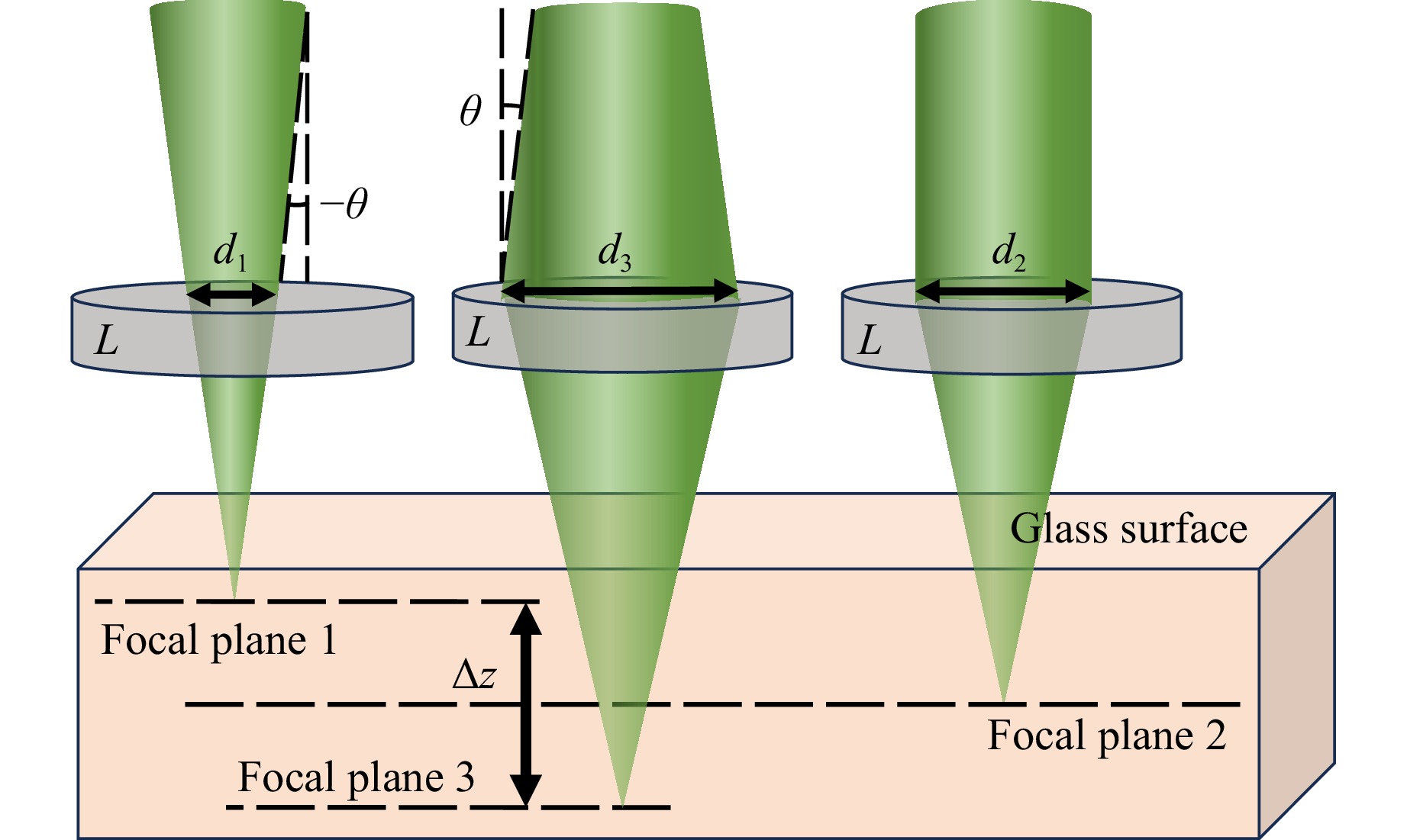
Fig. 1 Graphical representation of the Δz variation in glass as a function of the laser beam divergence. d1, d2, and d3 are the diameters of the laser beam at the lens entrance, L is the focusing optical lens, and θ is the laser beam divergence angle. Focal plane 1 is produced by a convergent beam, whereas focal planes 2 and 3 are created by a collimated and divergent beam, respectively.
The laser beam divergence angle was assigned positive or negative values to reflect the tendency of the laser beam to diverge or converge as it propagated. In the numerical analysis, we considered a Gaussian laser beam with an input diameter of 4 mm, a central wavelength λ of 532 nm, linear polarisation, and a glass with a refractive index of 1.51 for the laser beam propagation computations. Numerical simulations were performed using a plano-convex lens with a focal distance of 25 mm as the focusing optical component.
Simulations were performed considering three incident beam diameters corresponding to FFs of 25, 50, and 75%, respectively, relative to the optical limitation imposed by the focusing lens diameter used in our model. A broad range of divergence values (from −10 mrad to 10 mrad) was considered to examine large-scale variations and cover the most encountered experimental conditions. The variation of Δz as a function of the laser beam divergence showed a similar increasing trend (from negative to positive values) for all three FFs (25, 50, and 75%), indicating that the Δz significantly increased with increasing laser beam divergence, as shown in Fig. 2. Moreover, it can be observed that the focal point was positioned farther from the lens at a lower FF (e.g., FF = 25%), whereas it moved closer to the lens as the FF increased (e.g., up to FF = 75%). This shift is due to the relationship between the NA of the lens and diameter of the laser beam. A change in the laser beam diameter alters the NA, which in turn, influences the focal spot position. At extreme FFs of 25 and 75%, a shift of several hundred of micrometres occurred simply by changing the laser beam diameter. This demonstrated that variations in the laser beam diameter could affect the focal spot position, which in turn, influenced the performance of the optical set-up. A much more precise control over the focal point shift within a smaller range could be achieved by adjusting the laser beam divergence while maintaining the FF constant. By combining the variations of the FF and laser beam divergence, it was possible to induce larger axial shifts, demonstrating the high efficiency of the focal point control of the proposed method.
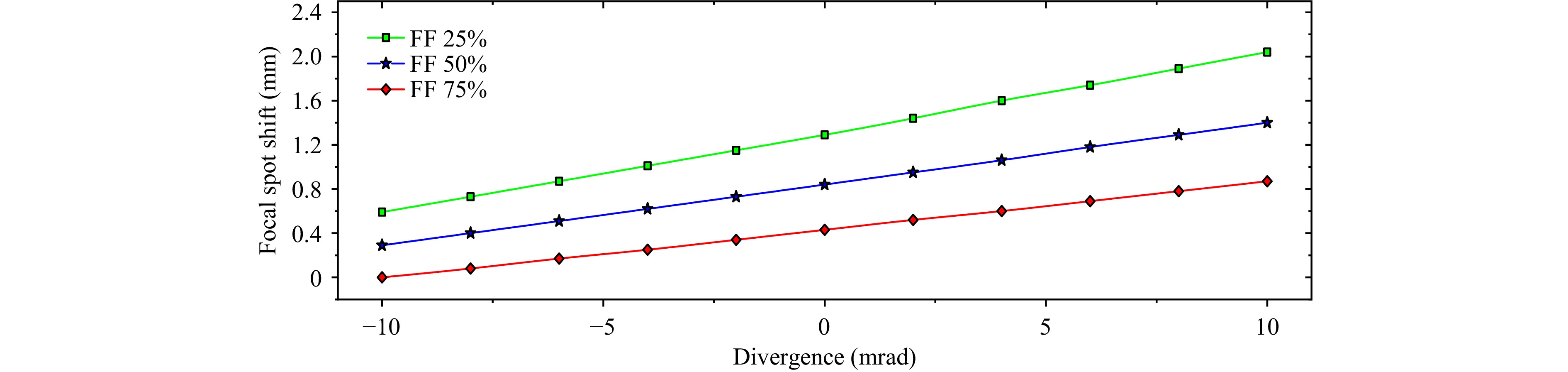
Fig. 2 Influence of the laser beam divergence on the focal spot characteristics for different FFs.
-
The theoretical results were verified experimentally using the optical set-up illustrated in Fig. 3. The set-up included a manual beam expander (MBE) designed to adjust the laser beam divergence, an automated XY translation stage (Aerotech Planar) with a 20-cm travel range and 500-nm accuracy to control the sample movement, a charge-coupled device (CCD) video camera to monitor the exposure process, and optical components to control the beam propagation.
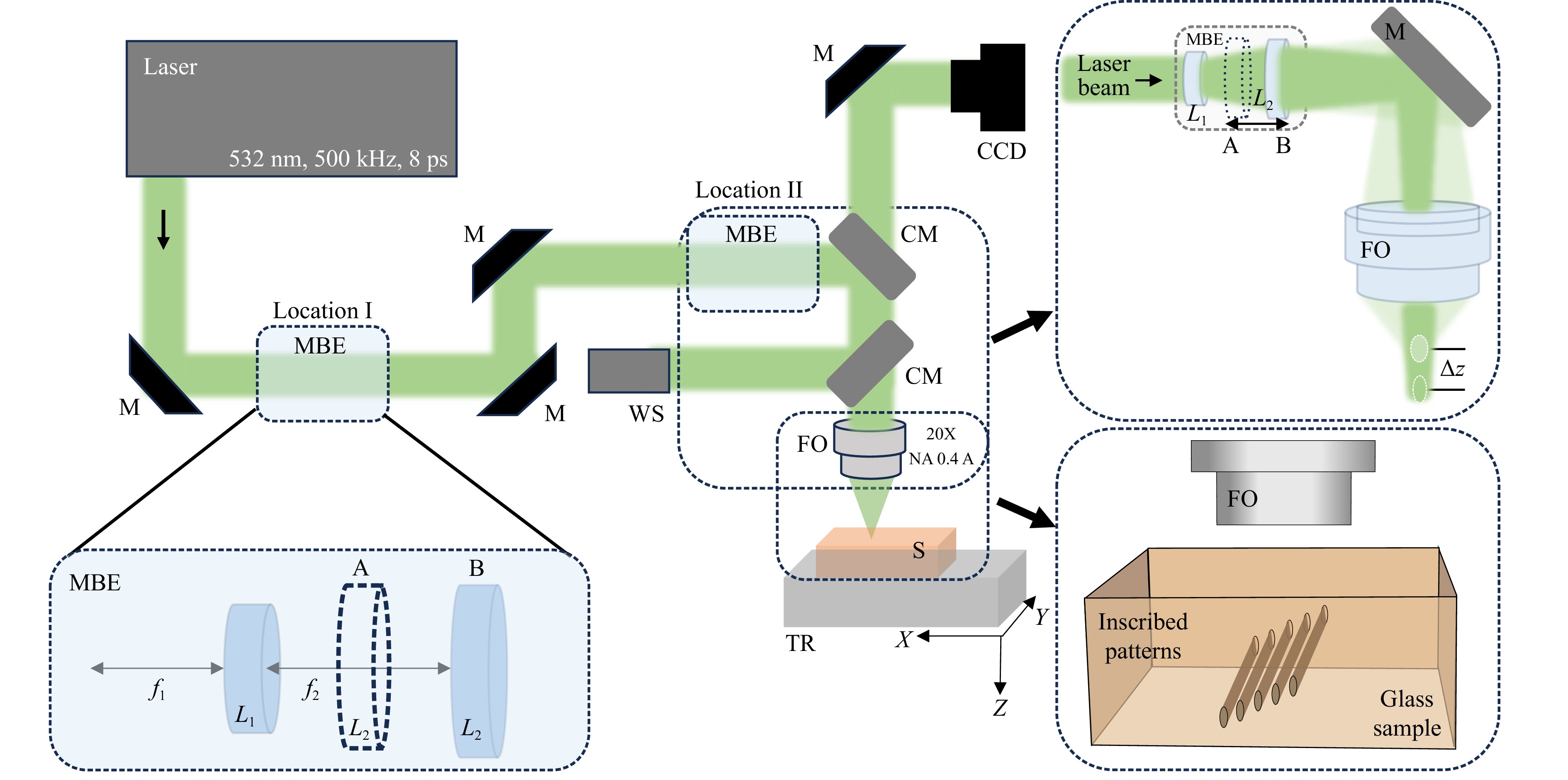
Fig. 3 Sketch of the set-up used for DFC to experimentally verify the influence of the laser beam divergence variation induced by the MBE on the focal spot shift. The MBE was based on two lens designs, with focal f1 = −50 mm and f2 = 100 mm. Here, M represents mirror, MBE represents manual beam expander, CM represents dichroic mirror, S represents sample, FO represents focusing optics, TR represents translation stage, CCD represents charge-coupled device video camera, WS represents wavefront sensor, and Δz represents focal point shift.
Different methods can be employed to control the laser beam divergence, including beam expanders based on optical lenses, optical fibres, diffractive optical elements (DOEs), and electronically controlled systems that rely on adaptive optics such as SLMs and deformable mirrors. Adaptive optics offers high flexibility and the dynamic control of laser beam properties is suitable for complex applications where real-time correction is required. A robust and simplified solution is to use an MBE that enables effective control of the laser beam divergence over a wide adjustable range. The MBE can be readily integrated into existing experimental set-ups, offers high optical efficiency, supports high-power laser operation, and ensures a stable and repeatable performance. In our experimental configuration, we implemented an MBE to generate different laser spot size magnifications and finely tune the laser beam divergence or precisely control the power density.
The effect of laser beam divergence on the shift and shape of the laser beam focal spot was studied experimentally by focusing a pulsed picosecond laser beam inside a transparent photosensitive glass (Foturan, Shott Gmbh) with a length × width × thickness of 15 × 15 × 1.5 mm. The picosecond laser source used in this study was the second harmonic (λ = 532 nm) laser of the Lumera HyperRapid 50 system with a pulse repetition rate of 500 kHz and pulse duration of 8 ps. The laser employed in this study was an industrial laser with an automated calibration system to check the oscillator stability. Amplification was based on diode pumping, which improved the overall system stability at a fluctuation of less than 2%, monitored within a period of 6 h. The high repetition rate further reduced the average power fluctuation. The beam was focused inside the bulk of the Foturan glass using a 20× objective lens with NA = 0.4 and a working distance of 6 mm as the focusing optics. To maintain a perfectly flat surface, a two-axis goniometer (Thorlabs GNL 20) was used to correct any deviations. The measurements revealed a precision of ±2 µm over the entire surface of the glass.
The main advantage of photosensitive glass over other SiO2 and oxide glasses is that it can be modified by a critical dose (photochemical reaction threshold), which is more important than the applied laser fluence. Such photochemical modifications are performed below the physical ablation threshold and can be exploited for material processing with successive wet etching29. By modifying the laser beam divergence while maintaining a constant laser power, patterns were created inside the glass for different values of laser beam divergence. The localised modification patterns created at the focal spot generated with different laser beam divergence values were then observed. Thus, each pattern written on the glass served as a “snapshot” of the focal spot created for a specific value of the laser beam divergence.
The glass inscription was initiated after the focal spot was translated within its volume at a depth of 750 µm by moving the microscope objective. At this position, the glass was exposed by tracing lines at a constant power of 50 mW and fluence of 3.18 J/cm2. Lines of a length of 5 mm, separated by 50 µm in an x-y plane, were inscribed inside the glass at a constant speed of 1 mm/s using an automated translation stage. At this speed, the laser system delivered material at ~500 pulses for each 1-µm stage movement, which significantly reduced the variation in size of the structure due to power fluctuations. From line to line, the laser beam divergence was systematically varied using the MBE by translating the L2 lens between positions A and B (Fig. 3), with a step of 0.5 mm. To properly evaluate the laser beam divergence measurements as well as the eventual wavefront changes induced by the MBE, a wavefront sensor was installed before the focusing optics.
-
Theoretical calculations predicted that the FF influenced both the axial shift and shape of the focal spot as the laser beam divergence varied. To generate different FFs, the laser beam diameter at the entrance of the focusing objective (FO) (DFO) was varied by placing the MBE at two different locations using the optical set-up shown in Fig. 3. Location I was set at a distance of 200 cm from the FO, which was the farthest distance allowed by our experimental set-up, and location II, set at 20 cm away from the FO, was the closest possible distance. In both cases, the beam divergence was measured using a wavefront sensor placed after the MBE to analyse the wavefront distortions and changes in the laser beam divergence.
-
We observed a significant variation in the DFO at the entrance of the FO with variations in the laser beam divergence angle controlled by the MBE when the MBE was placed at location I. At a maximum laser beam divergence of +0.62 mrad (divergent beam), a 5-mm DFO almost covered the FO, corresponding to an FF of 90%. In contrast, a minimum laser beam divergence of −0.99 mrad (convergent beam) corresponded to a DFO of below 1 mm and FF of less than 20%. The values of the laser parameters recorded by the wavefront sensor are presented in Fig. 4. It can be observed that at the maximum laser beam divergence, the deformation of the wavefront was comparable to the laser wavelength, as revealed by the graphical representation and root mean square (RMS) parameter. By reducing the laser beam divergence towards the collimated (DFO: ~3 mm) and convergent (DFO: ~0.7 mm) regimes, the wavefront deformation was significantly reduced, as supported by the low RMS and M2 values. The Strehl factor was estimated using wavefront measurements to evaluate the laser beam quality after passing through the MBE. The Strehl factor represents the ratio between the laser peak intensity calculated in the far field and the reference laser peak intensity for a flat wavefront. The Strehl factor reaches a maximum theoretical value of 1 for a perfect, aberration-free optical system. We noticed that, at both extreme values of the laser beam divergence, the Strehl factor was strongly affected by low-order, spherical and astigmatism distortions.

Fig. 4 Variation of the main laser beam parameters recorded by the wavefront sensor for the laser beam divergence extreme values and collimated beam, where the MBE was placed at location I. M2 is the beam quality factor, DFO is the beam diameter at the entrance of FO, θ is the laser beam divergence angle, RMS is the quantitative measure of wavefront aberration, where it also indicates the maximum phase difference in the analysis pupil and root mean square (standard deviation) of the phase in the same aperture similar to the peak-to-valley (P-V) factor), and Strehl factor is the ratio between the peak intensity of a real optical system and an ideal optical system.
However, the laser beam propagation through the FO produced uniform and well-defined focal spots for all laser beam divergence values, as observed in the scanning electron microscopy (SEM) images of the laser patterns in the photosensitive glass after chemical development (Fig. 5a). Each pattern corresponds to a laser beam divergence value within a range of 0.62 mrad to −0.99 mrad. Twelve distinct positions were generated by translating lens L2 from the MBE with a constant step shift of 0.5 mm. The laser beam divergence values were distributed as follows: 6 negatives (from θ = −0.99 mrad to θ = 0 mrad), 5 positives (from θ = 0 mrad to θ = 0.62 mrad), and one closest to zero placed at the centre (θ = 0.17 mrad) for the collimated beam. With variations in the laser beam divergence, the shapes of the developed patterns became more elongated along the Z-axis. The pattern height varied from h1 = 34 µm for θ = 0.62 mrad (inset A of Fig. 5a) to h2 = 59 µm for θ = −0.99 mrad (inset B of Fig. 5a), while the structure width slightly decreased from w1 = 13.5 µm for θ = 0.62 mrad to w2 = 11.5 µm for θ = −0.99 mrad. Consequently, the aspect ratio of the laser focal spot increased from 2.5 to 5 as the laser beam divergence decreased (Fig. 5b). A value of 2.5 might be associated with high NA objective characteristics, which allowed stronger focusing and more symmetrical focal spots, whereas an aspect ratio of 5 reflected a rather low NA system, where the focusing spot appeared more elongated30. Further increasing the laser beam divergence to a maximum value of −0.99 mrad seemed to affect the ability of the system to generate a uniform focal spot, as revealed by position C in Fig. 5a, in which a rather diffused structure was generated probably due to the insufficient photon density required to modify the photosensitive glass. By examining the distribution of the developed patterns, we found that the focal spot shift Δz was induced by the variation in the laser beam divergence. A maximum focal spot shift of 110 µm was obtained by measuring the distance between the patterns developed at positions A and B, as shown in Fig. 5b. Based on the reference of the collimation point, the maximum Δz was ~86 µm for the convergent beam whereas the maximum Δz was ~26 μm for the divergent beam. This indicated that the focal spot moved progressively farther from the FO as the laser beam divergence increased.
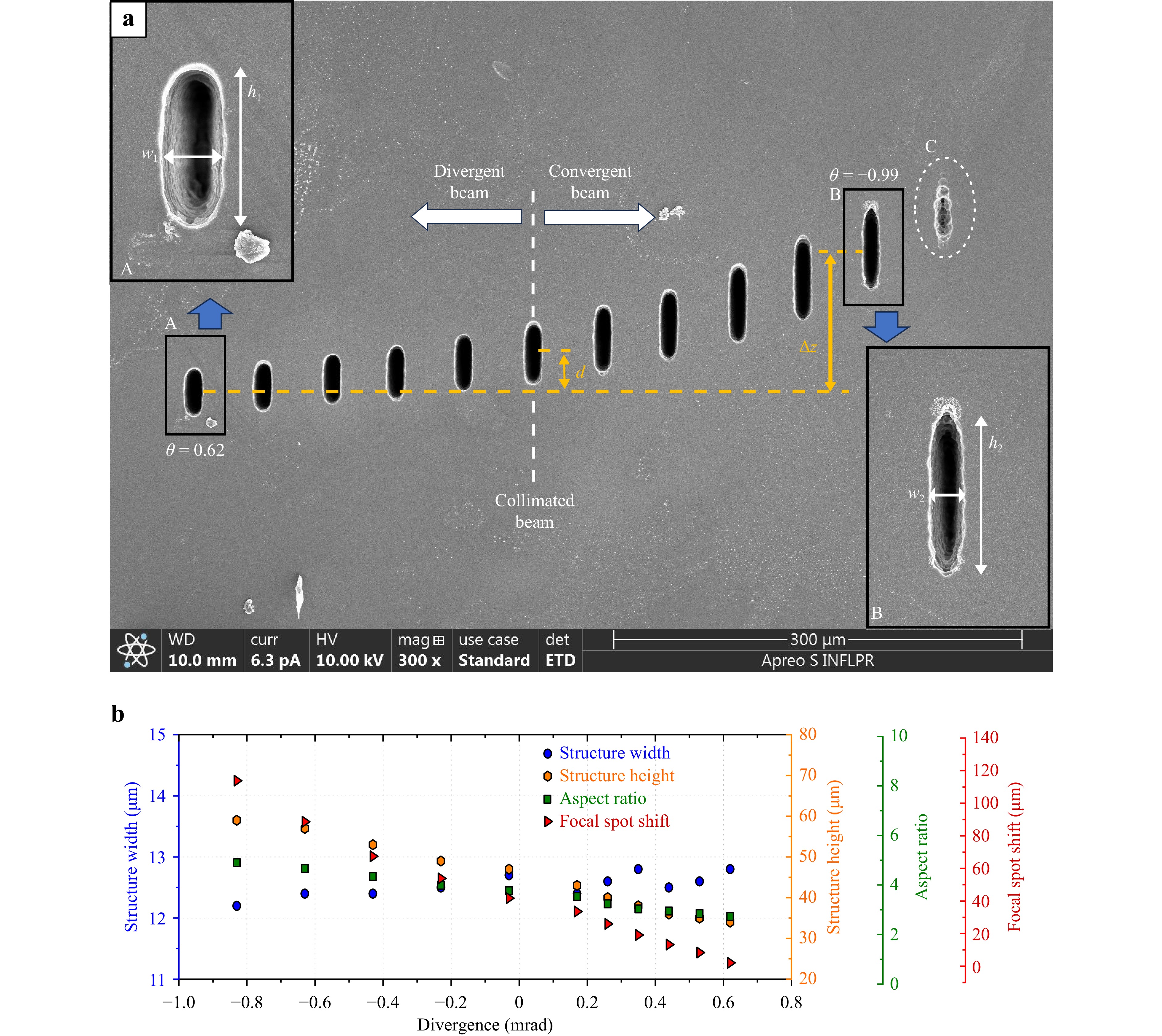
Fig. 5 Influence of the laser beam divergence on the focal spot shift and shape in the photosensitive glass when the MBE was positioned at location I. a SEM image of the developed structures induced by focus spots of the laser beam at various laser beam divergence angles controlled by the MBE, from +0.62 mrad (divergent beam) to −0.99 mrad (convergent beam). d indicates the working distance. The inset A shows the structure of the developed pattern of width w1 and height h1 at θ = 0.62 mrad. The inset B shows the structure of the developed pattern of width w2 and height h2 at θ = −0.99 mrad. b Dependence of the structure width, height, aspect ratio, and focal spot shift on the laser beam divergence.
-
At location II, the MBE was placed at a close distance of 20 cm away from FO. At a maximum value of 2.79 mrad (divergent beam), 5.8 mm of the DFO covered the FO, corresponding to an FF of 95%. A minimum laser beam divergence of −6.78 mrad (convergent beam) resulted in a DFO of ~1.25 mm and FF of less than 25%. The values of the laser parameters recorded by the wavefront sensor are tabulated in Fig. 6. It can be observed that at the maximum laser beam divergence, the deformation of the wavefront was five times larger than the laser wavelength, whereas it reached 1.36 at the minimum laser beam divergence. By reducing the laser beam divergence towards the collimated beam (DFO: ~4.2 mm), the wavefront deformation was significantly reduced, as indicated by the low RMS and M2 values. Both wavefront parameters were strongly affected by extreme laser beam divergence values, as revealed by the highest RMS parameter and lowest Strehl factor, whereas they exhibited good characteristics for the collimated beam.
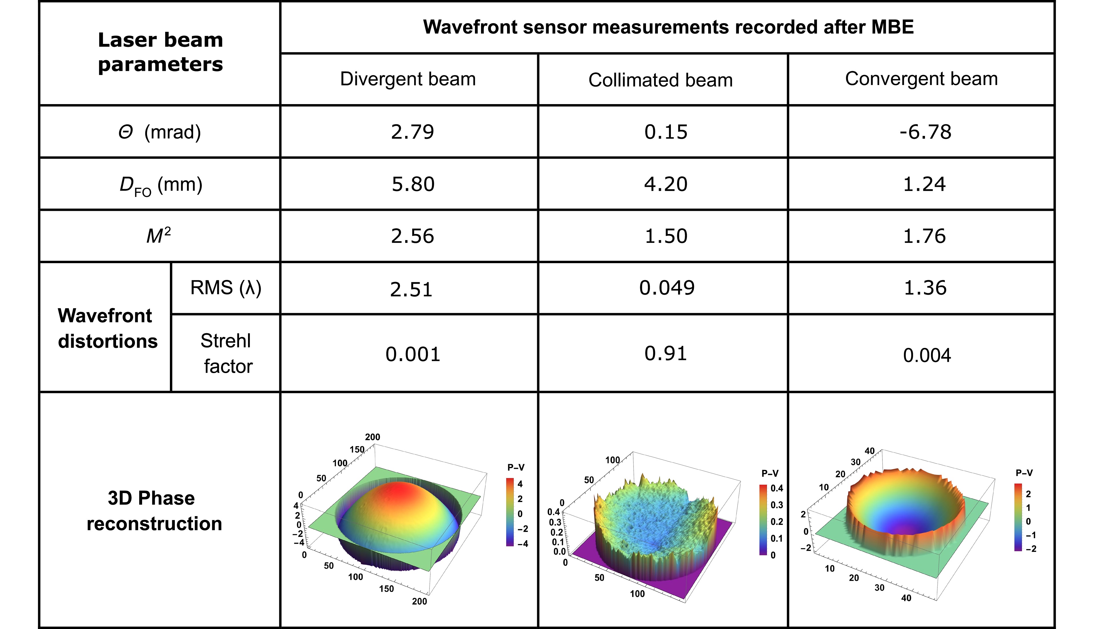
Fig. 6 Variation of the main laser beam parameters recorded by the wavefront sensor for the laser beam divergence extreme values and collimated beam, where the MBE was placed at location II. M2 is the beam quality factor, DFO is the beam diameter at the entrance of FO, θ is the laser beam divergence angle, RMS is the quantitative measure of wavefront aberrations, and Strehl factor is the ratio between the peak intensity of a real optical system and an ideal optical system.
Uniform and well-defined focal spots were observed for all laser beam divergence values, as shown in the SEM images of the laser patterns on the glass after chemical etching (Fig. 7a). These focal spots corresponded to laser beam divergence values ranging from 2.79 mrad to −6.78 mrad. A total of 78 distinct positions were generated by translating lens L2 from the MBEe while maintaining a constant step shift of 0.5 mm. These values were distributed as follows: 55 negatives (from θ = 0.15 mrad to θ = −6.78 mrad), 22 positives (from θ = 2.79 mrad to θ = 0.15 mrad), and one closest to zero placed at the centre (θ = 0.15 mrad) for the collimated beam. The maximum focal spot shift Δz was determined to be more than 900 µm between the centres of the structures located at the two most distant ends whereas the Δz became more pronounced as the beam transitioned from a collimated beam to an increasingly convergent beam (Fig. 7b).
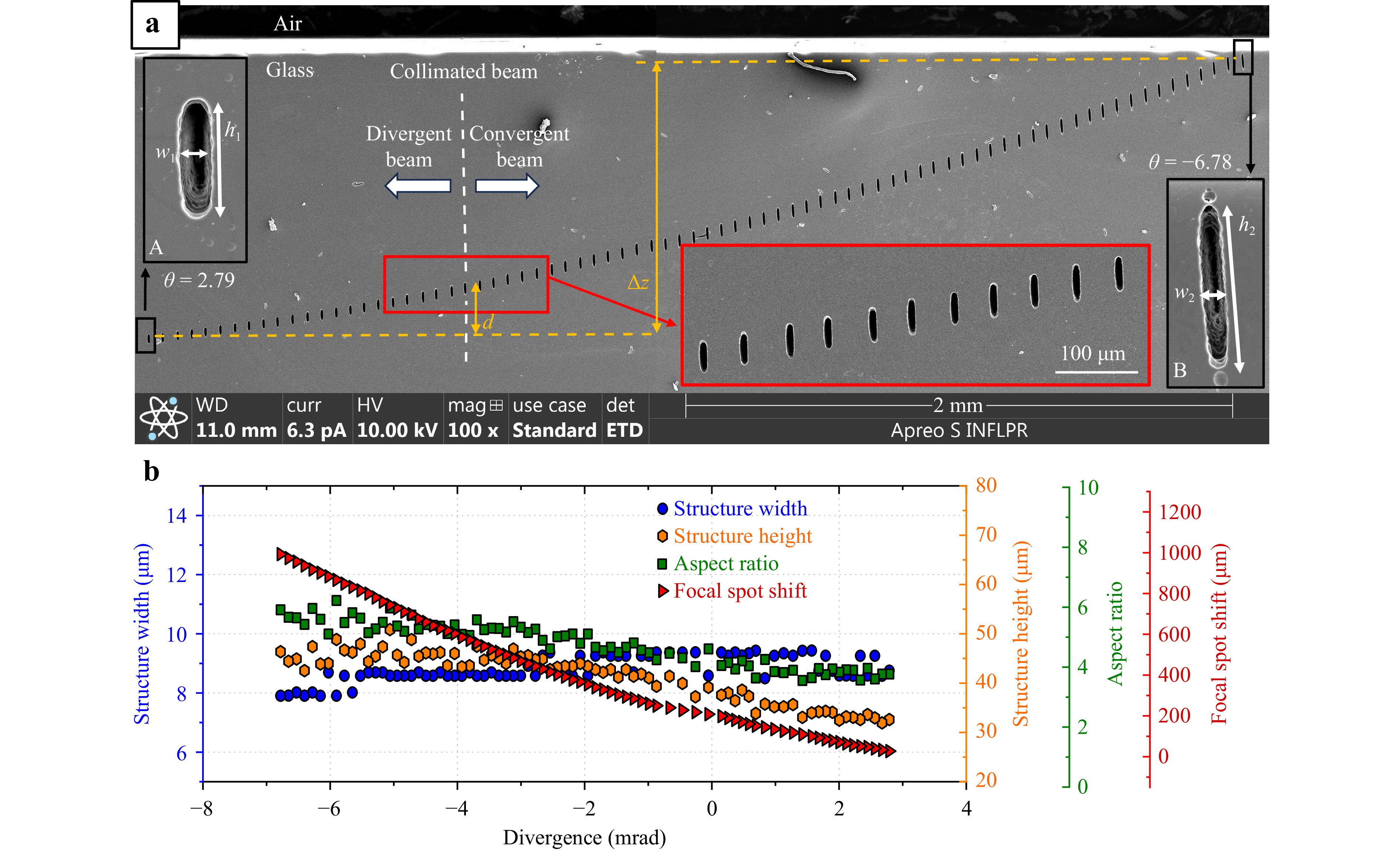
Fig. 7 Influence of the laser beam divergenc on the focal spot shift and shape when the MBE was positioned at location II. a SEM image showing the developed patterns inscribed in the glass by picosecond laser irradiation for different laser beam divergence values (merge of two SEM images). The inset A shows the structure of the developed pattern of width w1 and height h1 at θ = 2.79 mrad. The inset B shows the structure of the developed pattern of width w2 and height h2 at θ = −6.78 mrad. Here, d = 170 µm, which is the extended working distance. The magnified image of the patterns inscribed at the area enclosed with an open red rectangle using the same laser beam divergence values as those used for the MBE placed at location I (Figure 4) is also presented. b Dependence of the structure width, height, aspect ratio, and focal spot shift on the laser beam divergence.
In this configuration, the quality of the focus was better preserved for an extended range of laser beam divergence values. The effect of laser beam divergence on the focus shift and shape is shown in Fig. 7b, where each developed structure was evaluated in terms of the width, length, position, and aspect ratio. The width varied from w1 = 8.5 µm (inset A of Fig. 7a) to w2 = 8 µm (inset B of Fig. 7a), whereas the height increased from h1 = 32 µm to h2 = 47 µm within the same laser beam divergence range. It can be observed that the laser beam divergence had a negligible effect on the width of the focal spot over the entire interval (with a variation of less than 8%) whereas the variation was more significant at height of ~30%. This indicated a stable and relatively uniform shape of the inscribed structures and consequently, there was a correlation between the laser beam divergence and laser focal spot aspect ratio. By analysing the complete set of 78 laser-fabricated patterns, we found that the aspect ratio was ~4.8 ± 0.96. For a narrower subset of 11 consecutive structures, the aspect ratio was set to a nearly constant value of 4.
-
By examining the distribution of the laser-inscribed patterns across varying laser beam divergence values, it was evident that the Δz was dependent on the laser beam divergence and FF. When the incident laser beam was convergent, the rays inclined towards each other before entering the focusing optics, causing the focal spot to move closer to the lens system. Conversely, when the beam was divergent, the rays spread apart, resulting in the focal spot moving farther from the lens.
Different FFs were obtained by positioning the MBE at either Location I or II. In particular, the FF was adjusted exclusively by varying the laser beam diameter at the objective entrance pupil using both methods. In the first method, the distance between the MBE and focusing optics was varied while maintaining a constant laser beam divergence. In contrast, in the second method, the distance between the MBE and focusing optics was fixed, whereas the laser beam divergence angle was adjusted. By modifying the laser beam divergence, the laser beam diameter at the objective entrance pupil was varied, resulting in different FFs. In the ideal configuration, the NA of the focusing optics is fully covered by the laser beam, which corresponds to an FF of 1; however, if the beam diameter is much smaller than the aperture (FF << 1), the numerical aperture is affected, leading to an increase in the focal spot size. Considering the laser beam divergence angle (θ), the laser beam diameter at the entrance pupil (d), and the distance (l) between the MBE location and entrance pupil, the relationship between d and l is expressed as:
$$ d=2l{\rm{tan}}(\theta) $$ (1) At location I, the distance l between the MBE and focusing optics was strongly affected the laser beam propagation. Due to the small laser beam divergence angle of −0.99 mrad, the laser beam was nearly focused at the aperture of the focusing optics, resulting in a very low filling factor (FF << 1). Under these conditions, the focal spot height h2 was 59 µm. When the beam was expanded to a laser beam divergence angle of 0.62 mrad, the FF was increased to almost 1, resulting in a reduced focal spot height h1 of 34 µm, which agreed with the work of Tičkūnas et al.30 Within this rather limited laser beam divergence interval, 12 structures could only be fabricated by translating lens L2 of the MBE with a constant step of 0.5 mm (Fig. 5). Following this, to finely control the variation in the FF with laser beam divergence adjustments, the distance between the MBE and focusing optics was reduced to the shortest possible distance of 20 cm (location II). Hence, the distance was reduced by a factor of 10. In this case, a wider laser beam divergence range could be used, allowing the laser beam diameter at the entrance pupil to vary from a narrow dimension for FF << 1 at −6.78 mrad to a fully expanded beam for an FF of 1 at a laser beam divergence of 2.79 mrad.
At location II, variations in the FF caused by changes in the laser beam divergence were significantly reduced because the MBE was positioned closer to the FO. Maintaining a constant FF, regardless of the laser beam divergence variation, resulted in a stable and uniform focal spot, ensuring precise control over the energy distribution and ultimately improving the overall quality of laser processing. For the MBE placed at location II, we defined the region of achievable homogeneous processing as the range over which the focal spot size varied by less than 10%. The processing regions could be divided into three distinct depth ranges based on the observed variations in the focal spot shape: i) from the surface to a depth of 700 µm, ii) between a depth of 700 and 800 µm, and iii) from a depth of 800 μm to 900 µm. These regions are briefly described as follows:
i) This interval corresponded to a laser beam divergence range of −6.78 mrad to −1 mrad. Within this region, the focal spot width remained almost constant, whereas the height varied by less than 10%, from 47 µm to 43 µm. It can be noticed that the processing features remained flexible with higher aspect ratios at deeper glass volumes, whereas the lateral dimension of the focal spot was maintained with a variation of less than 10%.
ii) This interval corresponded to a laser beam divergence range from −1 mrad to 1 mrad, near the collimation point. In this region, the focal spot width remained constant, whereas the height decreased from 43 µm to 35 µm. It can be observed that the processed features transitioned towards compact aspect ratios because the near-collimated beam allowed more compact structures without compromising the lateral resolution.
iii) This interval corresponded to a laser beam divergence range of 1 mrad to 2.79 mrad. Within this region, the focal spot remained homogeneous, exhibiting only minor variations in width and height. Specifically, the dimension of focal spot width was fixed at a value of 8.5 ± 0.4 µm, whereas the height slightly decreased from 35 µm to 32 µm. The achievable processing resolution was correlated with the evolution of the FF30. Variations in the FF directly affected the energy distribution within the focal spot, which in turn, affected the consistency of the material processing. By actively controlling the beam properties through adaptive optics or a three-lens beam expander, it was possible to significantly reduce the FF fluctuations. This resulted in a more homogeneous processing resolution, ensuring that the laser–matter interactions were consistent across both lateral and vertical dimensions.
-
When the input field does not match the conditions for which the optical system is corrected or when misalignments are present, the output wavefront may deviate from an ideal plane or sphere. An ideal converging spherical wavefront can acquire aberrations after being transmitted through an interface to a medium with a different refractive index. The focal spot intensity distribution is shaped by the effective NA and spherical aberration, which degrade the achievable processing resolution30. Although these effects are generally less noticeable for objectives with a low NA, they cannot be entirely neglected. Even at moderate focusing angles, cumulative wavefront distortions at interfaces (e.g. air-glass) can influence the beam profile. Geometric optics does not describe the interference effect that occurs in the focal plane between different parts of the wavefront in the presence of aberrations, and it cannot fully capture the actual focal-field distribution or allow a direct comparison with the diffraction-limited case. The vector nature of the electromagnetic field is also relevant to focus at an appreciable NA. Therefore, a proper description of the laser beam propagation that accurately captures the field distribution in the focal region requires going beyond the geometric optics approximation and incorporating wave-optical effects. In this study, a theoretical study was conducted using ray-tracing propagation combined with vector diffraction theory to accurately reproduce the experimental results. Ray tracing offers high computational efficiency and provides a geometric description of the laser beam propagation and focal position through an optical system. In contrast, the vectorial implementation of the Debye diffraction integral31 enables a more rigorous treatment of the electromagnetic field, accurately capturing the polarisation effects, diffraction, and intensity redistribution in the focal region.
Wavefront measurements at the entrance pupil of the NA = 0.4 objective were used as the input for three illumination conditions (convergent, collimated, and divergent), with a beam diameter of 1.2, 4.2, and 5.8, respectively. We examined how the focal spot morphology affected by the laser beam divergence of the input field varied according to the experimental conditions. For all three cases, the measured wavefront was fitted with a sphere, which defined the equivalent point source used in Zemax OpticStudio software as the input source. The reconstructed fields were propagated through a dedicated Zemax file of the microscope objective and focused on the glass volume. A convergent field was used to establish the air distance between the objective exit and photosensitive glass interface. The air distance was fixed for the other two input fields. For each case, the ray intersections at the glass interface and focal plane, together with the optical path length from the point source to the glass plane, were determined using Zemax OpticStudio software and used to reconstruct the field at the glass interface. At the input pupil, the field amplitude was assumed to be Gaussian. Its width at the glass interface was estimated from the average ratio between the ray intersection coordinates in the glass and input planes, and the amplitude at the glass interface was assumed to be Gaussian with the corresponding scaled width. The phase in that plane was determined directly from the optical path length. The glass was described only by its refractive index at the working wavelength. From the reconstructed phase, the spherical phase corresponding to an ideal wave focusing on the focal point determined by Zemax OpticStudio software was removed, leaving a residual phase that represented the aberration accumulated during propagation. Starting from the field reconstructed at the glass interface, the field in the focal region was evaluated using the vector Debye diffraction integral, as described in the Materials and Methods section.
Fig. 8 shows the longitudinal profiles of the focal spot and the corresponding intensity distributions for each investigated case. This comparison highlights the effect of wavefront distortions on the shape of the focal volume and peak intensity achieved at focus. The intensity profile for each case was compared with the ideal situation, in which the contribution of spherical aberrations was removed. The focal spot corresponding to a divergent beam (2.79 mrad) is shown in Fig. 8a. In this configuration, the beam almost filled the objective aperture and was more sensitive to the accumulated aberrations present in the focusing geometry. Consequently, the focal region exhibited a distinct elongation along the propagation axis as well as redistribution of energy away from the central maximum. This behaviour was confirmed by the corresponding intensity profile (Fig. 8d), where spherical aberrations led to a significant reduction in the peak intensity at focus, down to ~30% of the value obtained in the ideal, aberration-free case. This strong degradation indicated that a substantial portion of the optical energy was spread to the surrounding regions, thereby reducing the effective resolution and processing efficiency. This effect became less pronounced when the laser beam was nearly collimated (0.17 mrad), as shown in Fig. 8b. In this case, the wavefront distortions were reduced, leading to a more confined focal spot, and the associated intensity profile (Fig. 8e) showed a higher peak intensity, reaching ~50% of the ideal case. Although spherical aberrations were still present, their effect on the focal field distribution was mitigated compared with the divergent beam scenario. When the beam was convergent (−6.78 mrad), the influence of spherical aberrations became negligible. As shown in Fig. 8c, the focal spot was well confined both longitudinally and transversely, closely approaching the ideal case. The corresponding intensity profile (Fig. 8f) indicated that the peak intensity at focus approached that of the aberration-free condition. In this regime, the initial wavefront curvature partially compensated for the aberrations accumulated during propagation, leading to an overall improvement in focusing performance. These results showed that the focal field distribution was sensitive to the illumination conditions at the objective entrance pupil. The strongest degradation of the focal spot was observed when the beam nearly filled the objective aperture, with a laser beam divergence of 2.79 mrad. In this case, the focal volume became elongated along the optical axis, and a larger fraction of the energy was redistributed to the surrounding side rings. In contrast, reduced pupil filling and laser beam divergence of −6.78 mrad led to a focal field closer to the ideal case with a high aspect ratio.
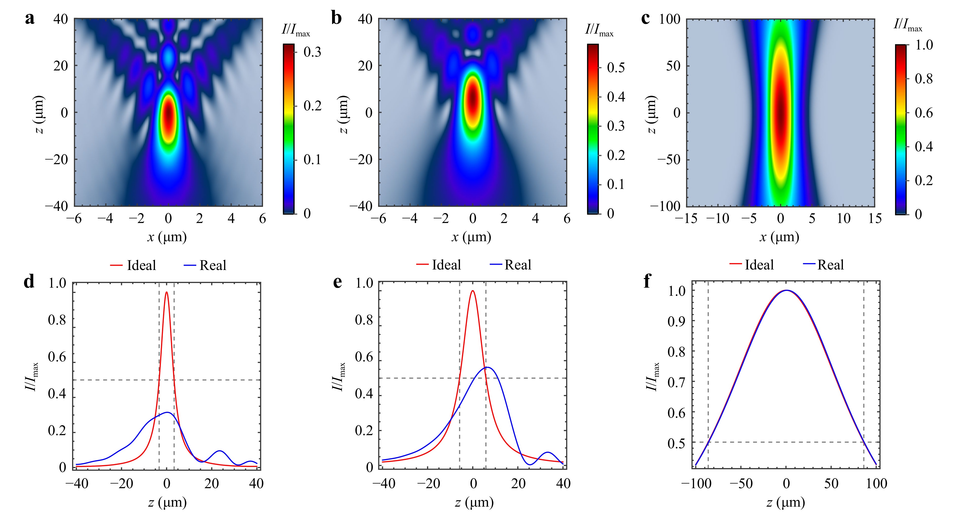
Fig. 8 Numerical simulation results for the focal spot morphology generated by the NA = 0.4 focusing objective inside of the photosensitive glass, using experimental data summarised in Table 2. Axial distributions of the focal spot for a divergent, b collimated, and c convergent beams. Intensity profiles at focus with and without spherical aberrations for d divergent, e collimated, and f convergent beams. The focal spot position was acquired from the Materials and Methods section.
-
The DFC concept introduced in this study was experimentally demonstrated by fabricating a 3D spiral microstructure geometry. This application served as a proof-of-concept, highlighting the efficiency and versatility of the DFC concept when integrated with laser direct writing methods. The working principle is illustrated in Fig. 9a, which presents a graphical representation of the laser beam trajectory during controlled divergence modulation using the MBE. The fabrication process involved a combined motion strategy that integrated an automated XY translation stage and MBE. The translation stage executed a circular motion in a single plane, defining the spiral diameter. Simultaneously, axial displacement of the focused laser beam was achieved by continuously adjusting and tuning the MBE between the two extreme positions. In this configuration, the rotational speed of the MBE dictated the axial displacement speed of the focal point, which directly controlled the spacing between the spiral turns and ultimately determined the geometry of the structure. A lower MBE rotational speed resulted in a smaller axial shift, producing tightly packed turns, whereas a higher rotational speed increased the spacing between the turns, reducing the total number of spirals. Furthermore, dynamic variations in the MBE speed enabled the fabrication of spiral structures with customised or non-uniform turn distributions.
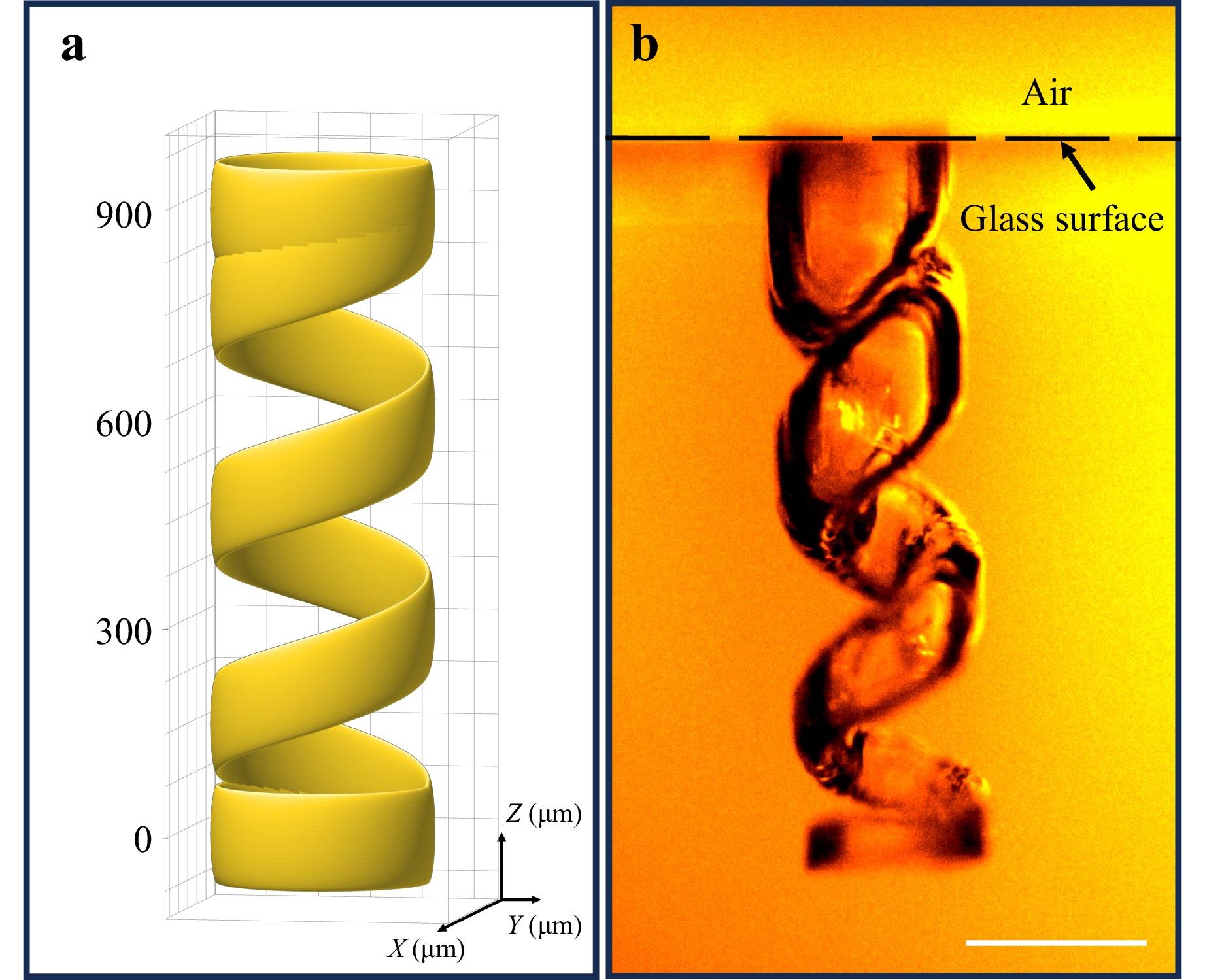
Fig. 9 Fabrication of a 3D spiral structure in Foturan glass using the DFC concept. a Graphical representation of the focal spot trajectory induced by MBE variation. b Optical microscopy image of the fabricated structure. The scale bar is 200 µm.
To experimentally validate the proposed concept, the laser beam was focused within the volume of the Foturan glass by positioning the MBE at location II, with a maximum laser beam divergence (θ = 2.79 mrad). The XY translation stage was programmed to follow a circular path with a diameter of 200 µm at a scanning speed of 50 µm/s, whereas the MBE was manually adjusted to gradually reach the maximum laser beam convergence angle (θ = −6.78 mrad), corresponding to a total axial displacement of 900 µm. After laser exposure, the Foturan glass underwent a standard processing protocol consisting of heat treatment followed by chemical etching in 8% hydrofluoric acid (HF) solution for 1 h. During this process, the laser-exposed glass volume was selectively removed, creating a 3D spiral structure, as shown in Fig. 9b. The fabricated spiral structure, which was affected by the etching process in the upper part of the glass, closely matched the programmed design parameters, thus validating the effectiveness of the DFC concept for generating complex volumetric microstructures. This experiment demonstrated the practical applicability of the DFC concept in direct laser writing for the fabrication of intricate 3D geometries. By decoupling the lateral and axial movements and providing precise control of the focal spot by varying the laser beam divergence, this method significantly broadened the design capabilities of volumetric laser microfabrication.
This processing method can also be applied to other transparent materials, making it adaptable to a broad range of materials commonly employed in 3D microfabrication. Among glass materials, fused silica exhibits better optical performance, with a broader transmission range and low autofluorescence. The development of 3D structures in volume is also possible with DFC processing by etching the laser-exposed regions in diluted HF solution, even without heat treatment, due to the physical reaction by the laser beam. In the case of photoresists, in which cross-linking is initiated through non-linear absorption for 3D fabrication, the DFC concept offers the advantages of parallel voxel generation and depth-selective curing. The DFC processing enables the simultaneous fabrication of multi-layered structures, significantly reducing the fabrication time compared with sequential layer-by-layer writing. In addition, the independent beam control allows the adjustment of the exposure dose for each focal plane, accommodating variations in resin sensitivity, shrinkage behaviour, or diffusion effects during polymerisation. The contribution of the refractive index to Δz is also important. When a laser beam enters a medium with a certain refractive index, the effective optical path length changes, causing the focus to shift deeper relative to the designed position in air. Hence, material-dependent variations in the refractive index should be considered when DFC processing is employed. Future studies should explore the integration of automated or software-controlled MBE systems to enable the fabrication of even more complex geometries with enhanced processing speed and repeatability.
-
Current multi-beam laser processing methods are limited in their ability to independently control the spatial position of each focused laser spot, particularly along the beam path. Laser systems are typically designed to generate multiple laser beams with lateral configurations confined to a single focal plane32–36. This allows simultaneous processing over a wide area in lateral dimensions to increase the throughput.
However, the absence of individual axial control for each beam limits the processing capability of the layer-by-layer approach. Such control is fundamentally advantageous for true 3D processing, enabling reduced fabrication time and enhanced resolution, and several attempts have been made to achieve this goal37–39. The implementation of the DFC concept in a multi-beam laser arrangement enables controlling the positions of multiple focal spots for parallel laser writing with high precision in the transparent material volume while simultaneously retaining the advantages of low-cost integration and high axial displacement.
In this study, we used a two-beam processing scheme and demonstrated its ability to individually manipulate two laser focal spots along the beam axis, which could be further extended to a multi-beam scheme. Validation was carried out by propagating the two laser beams through a single FO, where one laser beam divergence was independently controlled to define its focal position in three dimensions and generate parallel patterns at different depths with well-controlled distances along the beam axis in the photosensitive glass. By tailoring the laser beam divergence, the proposed method enabled dynamic adjustment of the focal shift without mechanical movement of the focusing lens.
The laser set-up configuration was then changed to allow the beam to split into two laser beams using a polarising beam splitter (BS 1): one split beam (laser beam 1) passed through the MBE (placed at location II) which controlled its laser beam divergence, and consequently, the axial position of the focal spot, whereas the other split beam (laser beam 2) was unmodified to maintain a fixed focal spot position determined by the focal length of the FO (Fig. 10). Furthermore, a half-wave plate (HWP) was placed before BS 1, enabling dynamic adjustment of the laser beam polarisation state, which tailored the power ratio, and controlled the energy distribution to the beams. The two beams were then recombined along the same optical path using a second polarising beam splitter (BS 2). The dual-beam configuration allowed the formation of two distinct focal spots (fs): the first focal spot (fs1) generated by laser beam 1 could be dynamically shifted by the MBE variation, whereas the second focal spot (fs2) corresponding to laser beam 2 remained fixed.
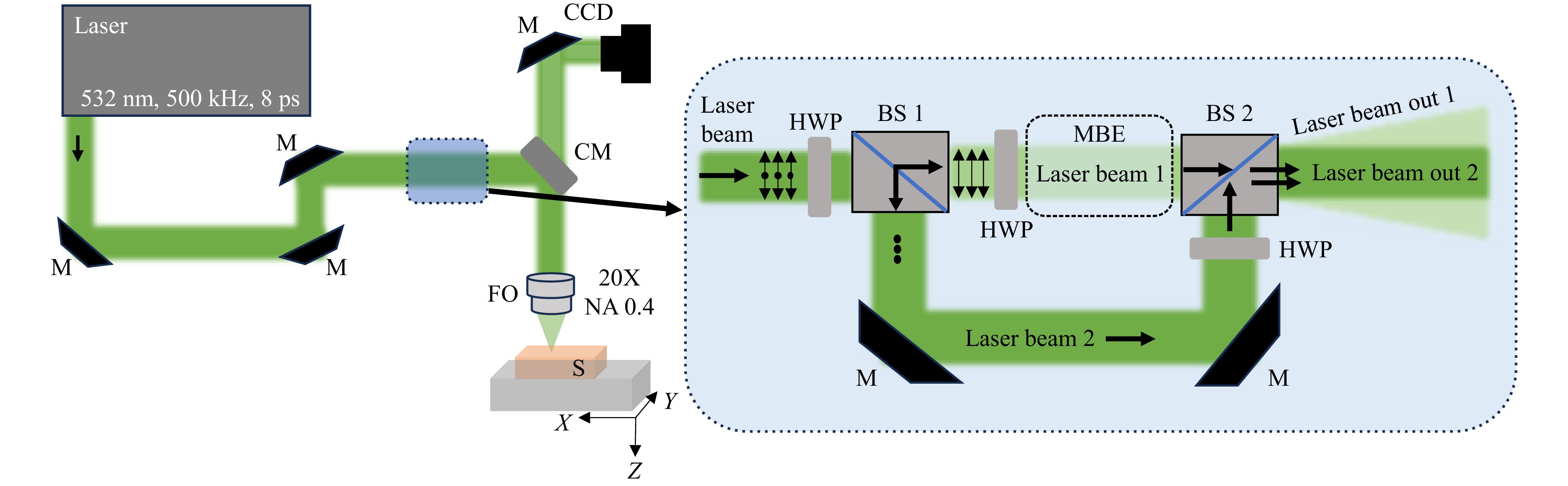
Fig. 10 Design of the optical set-up proposed for the generation of two independent laser beam paths. A combination of optical beam splitters and half-wave plates was used to divide and recombine the laser beam in a single optical path to test the DFC concept. The beam polarisation of each arm is indicated by double arrows and round dots. CM denotes dichroic mirror, FO denotes focusing optics, TR denotes translation stage, BS denotes beam splitter, HWP denotes half-wave plate, M denotes mirror, and MBE denotes manual beam expander.
In the new configuration, the two laser beams were focused by the FO in the photosenstitive glass. The total laser power was set to 100 mW to ensure glass modification by both beams40. By using the HWP, the power ratio was varied during processing by up to 20%, enabling real-time control of the power level of each laser beam. Parallel double-spot structures were fabricated in the photosensitive glass in a single scan and developed by etching using the same conditions as those in the previous experiment, as shown in Fig. 11. The fabrication scheme is presented in Fig. 11a, in which fs1 and fs2 simulate their axial position distributions during the dynamic adjustment of fs1 by the laser beam divergence of beam 1 (dashed lines) with a Δzmax of 900 µm, while maintaining a fixed position for fs2 (solid line).
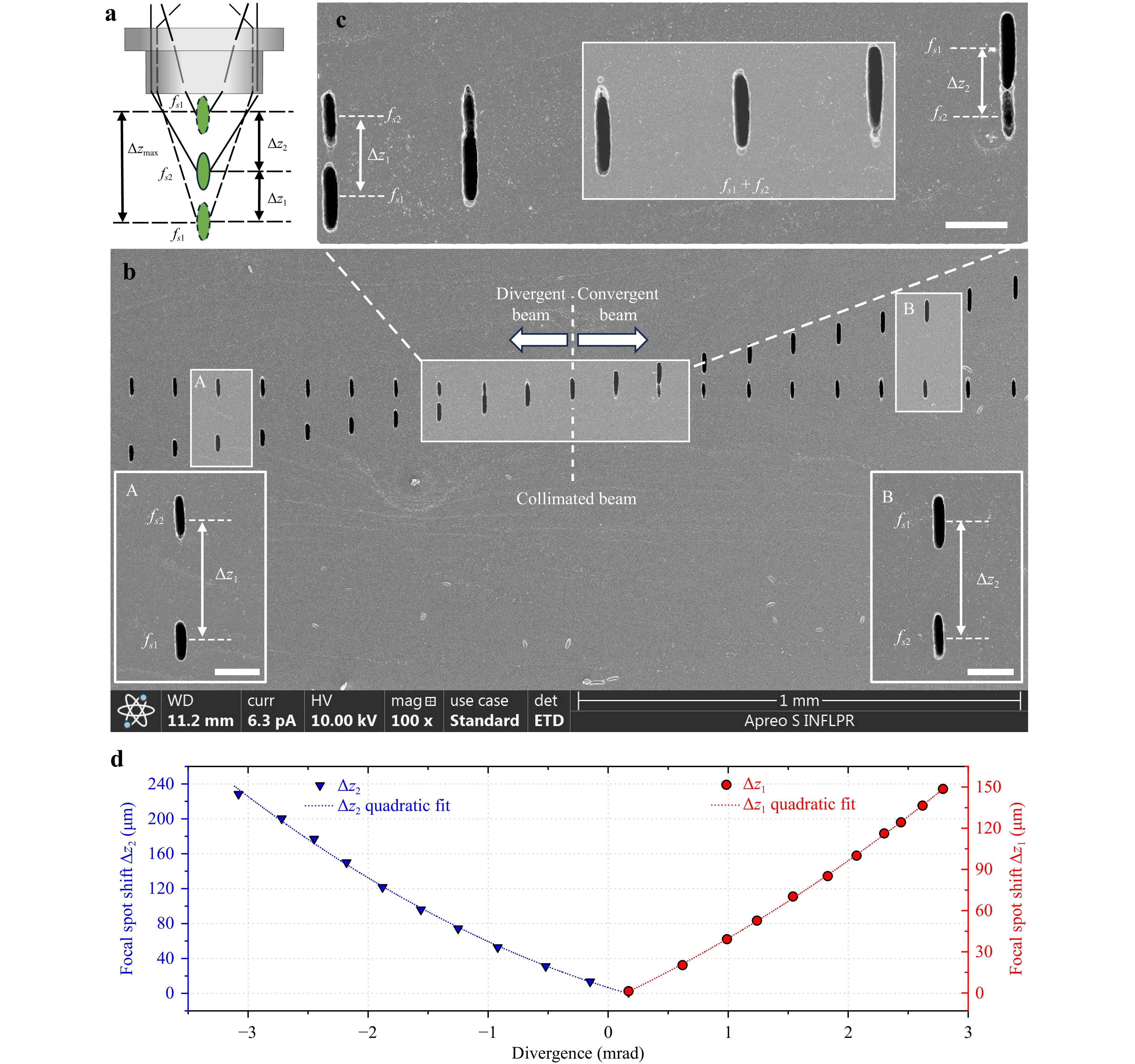
Fig. 11 Dual beam laser processing using a single lens design. a Schematic representation of the focal spot distributions for divergent, collimated, and convergent beams. b SEM image of the fs1 and fs2 distributions along the optical axis. The insets A and B indicate the fs1 position evolution related to the stable fs2 position. The scale bar for the insets is 50 µm. c Magnified image of patterns inscribed at the central region enclosed with a white open rectangle in b, where the fluence of fs1 is smaller than that of fs2. The fs1+fs2 marked area shows the overlapping of both focal spots at the same place. The scale bar is 50 µm. d Dependence of the focal spot shifts on the laser beam divergence.
The SEM image in Fig. 11b shows the 21 laser patterns consisting of a pair of parallel structures inscribed in photosensitive glass after chemical development with fs1 shift induced by varying the laser beam divergence from 2.79 mrad to 3.08 mrad relative to the fixed fs2. The positions of the 21 structures for fs1 gradually shifted upwards from left to right: 10 from the leftmost position corresponded to the divergent beam region, 1 at the centre corresponded to the collimated spot, and 10 from the rightmost position corresponded to the convergent region. The insets A and B in Fig. 11b show the spatial distributions of the two focal spots, clearly separated at distances Δz1 and Δz2, for divergent to collimated and collimated to convergent beam variation, respectively. A pair of parallel structures was fabricated using the same laser power of 50 mW for both laser beams, except for the central marked region, which is enclosed by an open white rectangle in Fig. 11b (the magnified image is also shown in Fig. 11c), for which the laser power was changed to 60 and 40 mW for laser beams 1 and 2, respectively. Thus, it is evident that the increased laser power for beam 1 increased the fs1 height, whereas the decreased laser power for beam 2 decreased the fs2 height at the leftmost point in Fig. 11c. Subsequently, fs1 overlapped a part of fs2 and was eventually superimposed on fs2 at the collimation point. At the rightmost point, fs1 separated towards the convergent regime. The evolution distances of Δz1 and Δz2 as the laser beam divergence varied in both investigated regions are shown in Fig. 11d. Thus, the combination of DFC with laser power variation is beneficial for ultrafast laser processing of transparent materials, particularly for multi-beam focusing in volume with individual control of the deposited energy at each spot.
To model the dependence of the focal spot separation (Δz) on the laser beam divergence angle θ, we performed separate quadratic fits for positive and negative laser beam divergence values, since the experimental data exhibited slight asymmetry, using the following mathematical expression:
$$ \Delta {\textit z}(X)=aX^2 +bX + c $$ (2) The coefficients (a, b, and c) were determined using the FindFit, a built-in function provided in Wolfram Mathematica software, which enables non-linear regression and parameter estimation. A second-degree polynomial (quadratic function), as given by Eq. 2 was fitted to the experimental dataset. The procedure minimized the sum of squared differences between the measured values and those predicted by the model using least-squares optimisation. Hence, the obtained coefficients represented the best-fit parameters that described the underlying trend of the experimental data within the framework of a quadratic relationship. The resulting coefficients for the quadratic fits are given by:
$$ {\Delta {\textit z}}_{{1}} {(\theta )\approx 3.195 \theta }^{ {2}} +{47.53\theta -7.685\;\;(\theta \geqslant 0)} $$ (3) $$ {\Delta {\textit z}}_{ {2}} {(|\theta |)\approx 9.483|\theta|}^{ {2}}- {45.104 |\theta|+4.808\;\;(\theta <0)} $$ (4) where θ is in mrad and Δz is in µm. These equations provided an accurate predictive model of focal spot separation across the measured laser beam divergence range from Fig. 11, capturing both the main linear trend and slight curvature observed experimentally. Here, each discrete change in the laser beam divergence corresponded to a 1-mm translation step of the MBE lens along the optical axis. Although the focal position could be continuously tuned by adjusting the laser beam divergence angle, the precision of the practical axial control precision was fundamentally linked to the mechanical translation of the lens. Analysis of the resulting focal spot shifts showed that a 1-mm lens displacement produced changes in the focal spot separation of ~13 µm to over 20 µm per step, depending on the laser beam divergence interval. This indicated that the axial focal position could be controlled with a resolution on the order of tens of micrometres per millimetre of lens movement. Reducing the lens translation step from 1 mm to 0.1 mm would significantly improve the axial control accuracy by a factor of 10 and proportionally reduce the minimum achievable focal position increment to the micrometre scale, roughly 1.3–2 µm using an actual MBE configuration.
These findings indicated that the focal position might be finely tuned by improving the adjustment control of lens L2 of the MBE. In our configuration, the L2 lens position was achieved through mechanical fine adjustment, which might have been influenced by operator-dependent variances. To overcome these limitations, a motorised fine-adjustment stage for lens L2 can significantly enhance the positioning accuracy, repeatability, and stability. Implementing motorised actuation will allow this displacement to be executed with higher precision and reproducibility, while also enabling programmable control for systematic parametric studies. For example, with a lens displacement of 5 µm, one can induce a focal spot shift of 60–250 nm, depending on the laser beam divergence value. A motorised system with closed-loop feedback can mitigate the mechanical jitter or transient instability, resulting in smoother motion profiles and improved mechanical stability. This level of control is essential for laser processing applications where the nanometre-scale increment of the focal spot will affect the quality and resolution of the resulting 3D patterns. This can enhance system robustness and application scalability. Overall, understanding and controlling the relationship between the laser beam divergence, focal spot size, and FF evolution will enable precise tailoring of the processing parameters and optimisation of the feature uniformity, aspect ratio, and overall quality across the entire tuneable range of the experimental set-up.
Various advanced laser processing methods have demonstrated their efficacy in precisely controlling the position and spatial energy distribution of laser beams using active and passive electronic devices. However, maintaining a sharp focal spot (without optical aberrations) during an axial shift of hundreds of micrometres remains challenging.
Several methods have been demonstrated to achieve axial focal shifting, each exhibiting distinct trade-offs in the axial shift range, precision, cost, and implementation complexity. Table S121,22,24,25,41–68 provided in the Supplementary Information (SI) summarises the existing methods employed to control the axial position of the focal spot, indicating the working principle, achieved axial shift, as well as benefits and limitations. In this study, we introduced the DFC concept to enable precise axial shifting of the laser focal spots. For NA = 0.4, this method allowed axial shifts of up to 900 µm, representing one of the largest among passive optical methods. The DFC processing offers a low-cost and low-complexity solution with high mechanical and thermal stability due to the absence of active electronic components. However, it does not provide control over the wavefront shape or spherical aberrations, which limits its resolution and adaptability for high-precision applications. Alternatively, DOEs provide a compact and static substitute, which have been shown to provide axial shifts of up to 114 µm for NA = 0.422 and 140 µm for NA = 0.9541. Even though DOEs can be cost-effective and offer moderate complexity, the available axial tuning range is significantly smaller than that of beam expanders and is deficient in terms of dynamic tunability. Although the resolution can be high, the flexibility is limited because of the fixed phase profile. The Alvarez lens enables continuous focal tuning through the lateral displacement of two complementary phase elements, typically achieving axial shifts of several hundreds of micrometres when microscopic objectives are used. Although it provides relatively large tuning ranges and good repeatability, its performance is constrained by mechanically induced motion, suffering from response times typically limited to tens to hundreds of Hertz, as well as increased system complexity and alignment sensitivity, at a moderate cost. Deformable mirrors (DMs) are alternatives for axial focal modulation, which dynamically reshape a reflective surface using an array of actuators. Axial shifts of ~53 m at NA = 142, 85 µm at NA = 0.7543, 100 µm at NA = 0.844, and up to 240 µm at NA = 0.445 have been attained. This method offers a very high resolution due to sub-wavelength phase control and fast response times in the kilohertz regime, along with the capability to correct higher-order aberrations. However, DMs are expensive and have a high system complexity. Furthermore, their axial range remains limited, especially at a high NAs. Electrically tuneable lenses (ETLs) provide axial focusing through refractive index modulation induced by electrical actuation with maximum axial shifts of 350 µm at NA = 0.446. These devices offer a good trade-off between cost, compactness, and flexible integration, with response times of 1–10 ms. However, they exhibit hysteresis, thermal drifts, and optical aberrations, which can reduce the effective resolution. SLMs offer programmable wavefront shaping, enabling precise and flexible control of the focal position. Axial shifts of up to 500 µm for high-NA configurations47 and up to 800 µm for NA = 0.4521 have been achieved. SLMs offer very high resolution and unmatched flexibility, including aberration correction and multi-plane generation. However, SLMs are costly, have high system complexity, and are limited by relatively slow refresh rates and low optical efficiency. TAG lenses achieve axial focal modulation through high-frequency acoustic excitation of a refractive index gradient within a fluidic medium. These lenses provide axial shifts of up to 600 µm at NA = 0.2548 under optimised conditions. This highlights a strong dependence of the axial shifts attained by TAG lenses on the NA, where the axial shift significantly decreases at high NAs. TAG lenses operate at very high frequencies far exceeding those of other methods, making them ideal for ultrafast scanning. Nevertheless, the focal position follows a sinusoidal trajectory, preventing static positioning, and the system requires precise synchronisation. In addition, the complexity and cost are relatively high, and full wavefront control is not available. In this context, beam expanders provide the largest axial shift range at low NAs with minimal cost and complexity. However, they lack precise control of the wavefront. DOEs and DMs offer high resolution but with a limited axial range, whereas ETLs and SLMs represent intermediate solutions, balancing range and good control but they are more expensive and complex. TAG lenses are better in terms of speed and dynamic range at lower NAs but they are constrained by their non-static operation and reduced focal spot shift performance at high NAs. From this perspective, the optimal choice depends strongly on the application: high-throughput systems may require TAG lenses, high-precision applications require DMs or SLMs, and cost-efficient and large-range calibration-free industrial applications may necessitate DFC processing.
To achieve extended axial control, various strategies have been explored over the years. Adaptive optics systems such as DMs and SLMs allow dynamic wavefront shaping, enabling millimetre-scale control of focal positioning without mechanical movements. For instance, Kopf et al.69 used a DM to change the focal length of a lens up to the 3.6-mm range in a high-power focusing system, whereas Verpoort et al.70 combined a unimorph DM with an f-theta lens to achieve modulation of the focal position over a notable 60-mm range. These extended shifts are produced by optical lenses with long focal lengths, which are not compatible with laser microfabrication applications that typically require tightly confined focal spots with reduced aspect ratios for high-resolution processing. Even though these systems offer superior flexibility, speed, and precision, they are inherently complex, require precise calibration, and are typically associated with high implementation costs.
By implementing DFC processing, we achieved axial shifts of the focal spot over 900 µm without a significant loss in the focus quality, as confirmed by the experimental inscription of patterns in a photosensitive glass. This extended shift is attributed to the focal length and large aperture of the focusing optics, which are further augmented by the refractive index of the glass. As the tuning distance increases, the contributing beam angles approach the limit set by the NA, which ultimately restricts further extension of the tuning range. Optical aberrations introduced by the focusing optics can become more significant at larger effective laser beam diameters or incidence angles, potentially degrading the focal quality. Future improvements in the technique can be achieved through active control of the laser wavefront using adaptive optical elements, such as DMs or SLMs, which can correct wavefront changes and maintain optimal focusing conditions over a wider axial range. In addition, larger focal shifts may be obtained by employing microscope objectives with higher apertures or optimised optical designs that reduce aberrations and improve the beam filling of the focusing optics. Furthermore, we demonstrated the efficacy of the DFC concept in controlling the spatial localisation of two laser focal spots within a sample volume, thereby offering new perspectives for parallel laser processing. Other methods have been investigated such as multi-beam laser processing, offering a promising solution for scalable micromanufacturing on large surface areas. Meyer et al.33 introduced a novel approach for ultrafast laser material processing by developing a multi-beam system where each beamlet was individually addressable in the same focal plane. This configuration enhanced both the flexibility and scalability of ultrafast laser systems and enabled high-speed processing of intricate structures. Similarly, Zunino et al.35 proposed the use of acousto-optofluidic system to diffract light into multiple beamlets, marking the first demonstration of this method for customised multi-focus generation in laser material processing. In addition, Finger et al.32 developed a method where a matrix of beamlets was generated and individually modulated using acousto-optic modulators, thereby offering dynamic control during processing. Despite their versatility, these multi-beam systems typically operate in a fixed focal plane and require Z-scanning mechanical components to build 3D structures layer-by-layer. Moreover, there are mechanical constraints with these methods, which limit their ability in achieving fully dynamic, volumetric fabrication without compromising throughput or spatial resolution.
In contrast, DFC processing allows precise tuning of focal positioning within the sample volume of multiple laser beams independently, enabling simultaneous generation of multiple focal spots at different depths within the same optical system by tailoring the laser beam divergence.
A multi-beam processing approach is a promising tool designed to significantly enhance productivity in manufacturing applications, overcoming the limitations of conventional layer-by-layer scanning methods. The integration of a SLM or DOE can further enhance the versatility and performance of DFC processing by increasing the number of laser beams. In particular, SLM enables dynamic, programmable wavefront shaping, allowing real-time control of the beam phase and amplitude to facilitate adaptive focal positioning, on-demand generation of complex 3D focal distributions, and compensation for system aberrations or sample-induced distortions. In addition, SLM-based control allows independent intensity balancing among multiple foci, improving the uniformity and process reliability during parallel fabrication. Alternatively, DOE can provide a compact and robust solution for generating predefined multi-focus patterns with high efficiency and excellent spatial stability. The DOE may offer superior mechanical robustness and simplicity, making it more attractive for industrial environments. Such capabilities open new possibilities for advanced microfabrication techniques across various industrial and research domains, such as the manufacturing of photonic, optoelectronic, and microfluidic devices, for which precise 3D structuring and high efficiency are simultaneously required.
-
In this paper, we introduced a new approach for parallel laser writing in a volume of transparent materials based on the DFC concept, where a precise axial shift of the focal spot along the beam axis can be induced by changing the laser beam divergence. Numerical simulations confirmed the influence of different incident laser beam diameters on both the focal spot axial shift and shape in response to variations in the laser beam divergence. Ray-tracing propagation combined with vector diffraction theory demonstrated that the initial laser beam divergence played a critical role in determining the extent to which spherical aberrations affected the focal field distribution, which in turn, influenced the processing performance. Experimental validation of the influence of the laser beam divergence variation induced by an MBE on the laser focal spot axial shift and shape was supported by the inscribed patterns developed in a photosensitive glass volume, where a maximum axial shift of 900 µm was achieved. Furthermore, by adjusting the laser beam divergence, parallel ultrafast laser processing was achieved by simultaneously employing two laser focus spots to inscribe parallel patterns aligned to the beam axis with well-controlled distances in the photosensitive glass.
This new processing method has the potential for multi-beam laser writing and microfabrication inside transparent materials with high precision and efficacy, particularly for structuring over extended areas and parallelising 3D material processing methods, making it an attractive solution for both research and industrial applications. This process capability also holds significant promise for next-generation imaging modalities.
-
The Optica package available in Mathematica software is a specific optics simulation package developed for the design and modelling of complex optical systems. The basic computational mechanism used to design the lens and compute the optical path combines ray tracing, symbolic calculations, and numerical optimisation. All the ray-tracing computations (optical component design, focusing, etc.) satisfy Fermat’s principle which states that light leads the path that minimises the optical path length between two distinct points. Fermat’s principle is essentially imposed in the Optical package through ray tracing obeying Snell’s law, surface definition, and ray path numerical optimisation. To design the optical lens, the primary equation used by the Optica package is Lensmarker’s formula, which is expressed as:
$$ \frac{1}{f}=(n-1)\left(\frac{1}{{R}_{1}}-\frac{1}{{R}_{2}}\right) $$ (5) where f is the focal length, n is the refractive index of the lens material, R1 is the radius of curvature of the first surface, and R2 is the radius of curvature of the second surface.
The optical path length (OPL) plays a crucial role in understanding how light accumulates the phase and determines the focal point and interferences. The OPL is typically calculated as follows:
$$ OPL=\int n(\overrightarrow{r})ds $$ (6) where $ n(\overrightarrow{r}) $ is the refractive index at position $ \overrightarrow{r} $ and ds is the differential element along the ray path. In our simulations, we considered a ray segment inside a uniform medium, which is expressed as:
$$ {OPL}_{\rm{segment}}=n\cdot L $$ (7) where L is the geometric path length through the medium.
In the Optica package, for ray tracing, each ray segment (denoted by “i”) contributes $ {n}_{i}\cdot {L}_{i} $ to the total optical path length and they are summed across all surfaces and media. At each light optical component incidence, the Optica package applies Snell’s law to determine the new direction of the reflected or refracted ray:
$$ {n}_{1}\mathit{\sin } \left({\theta }_{1}\right)={n}_{2}\sin ({\theta }_{2}) $$ (8) where $ {n}_{1} $ and $ {n}_{2} $ represent the refractive indices of the first and second media, respectively, $ {\theta }_{1} $ is the angle of incidence, and $ {\theta }_{2} $ is the angle of refraction. In vectorial form, Snell’s law can be expressed as:
$$ \overrightarrow{T}=\frac{{n}_{1}}{{n}_{2}}\overrightarrow{I}+\left(\frac{{n}_{1}}{{n}_{2}}\mathit{\cos } \left({\theta }_{1}\right)-\cos \left({\theta }_{2}\right)\right)\overrightarrow{N} $$ (9) where $ \overrightarrow{I} $ is the incident ray direction, $ \overrightarrow{T} $ is the transmitted (reflected) ray direction, and $ \overrightarrow{N} $ is the surface normal at the point of incidence. This numerical tool provides a description of customised optical systems based on an extensive database of various materials and optical elements.
-
Foturan glass is known for its ability to undergo localised chemical modifications when exposed to a laser beam under non-linear excitation conditions71,72 only in areas where the photon density reaches the modification threshold40. This allowed us to record any changes in the focal spot shape and shift inside the glass in our experimental configuration. The energy deposited by ultrashort laser pulses in transparent materials produces highly localised material modifications with minimal heat-affected zones in the interaction volume. Consequently, the interaction volume does not undergo significant heating, which may affect the focal position of the beam. However, in the high-repetition regime, exceeding several hundred kilohertz, heat accumulation cannot be ignored73. In addition, for picosecond laser pulses, the possible thermal accumulation may be more pronounced and slightly increase the modified glass volume compared with femtosecond laser pulses, making 3D processing more efficient for large-scale microfabrication. In this study, several aspects of the experimental method were considered to minimise the effect of heat accumulation. Glass exposure was performed in a scanning regime at a relatively low laser fluence, just above the chemical modification threshold, which was lower than that of the physical modification regime. Moreover, the influence of the scanning speed and etching rate was investigated to optimise the processing parameters and minimise possible heat accumulation effects. Consequently, the heat accumulation effects (commonly observed in high-repetition-rate stationary irradiation) were suppressed, minimising possible focal shifts during 3D processing. The eventual weak heat accumulation might have slightly increased the modified glass volume but did not alter the focal shift. By adjusting the laser power to exceed the photochemical modification threshold of the glass only at the focal volume, we ensured that chemical changes could occur only at the focal spot. By precisely adjusting the laser beam divergence, it was possible to observe slight changes in the focal position along the beam axis where chemical modification occurred. To visualise the modification, hollow microstructures were fabricated inside the Foturan glass using picosecond laser irradiation, followed by heat treatment at 605 °C and chemical etching in HF solution. In the experiments, we used an etching time of 5 min in an 8% HF solution, followed by cleaning with distilled water in an ultrasonic bath. The etching variability in the measurement of the focal spot shift was considerably low because the etching process was performed simultaneously for all written structures. Characterisation of the chemical modifications of the Foturan glass was performed after sample polishing using a Thermo Fisher Scientific Apreo S LoVac scanning electron microscope. Spiral structure in Foturan glass was characterized through widefield fluorescence microscopy using a Nikon Eclipse Ti2 inverted microscope equipped with a 10x / 0.45 NA objective. Fluorescence signal from rhodamine 6G was captured with excitation and emission wavelengths centered at 561 nm and 613 nm, respectively.
-
A plano-concave lens (L1) with a focal length of −50 mm was used to expand the beam, followed by a plano-convex lens with a focal distance of 100 mm. The two lenses were mounted on a variable tube lens holder with a total shift of 50 mm, allowing precise adjustment of the distance between them. The plano-concave lens remained fixed, whereas the plano-convex lens was translated along the beam axis without any rotation using a double-helical mechanism installed in the tube lens. The maximum magnification factor of the MBE with this configuration was 2×.
-
A wavefront sensor at the beam expander output (Phasics CCD camera) was used to record the properties of the laser beam. This sensor was based on the Quadriwave lateral shearing interferometry method (QWLSI)74,75, and accurately recorded the modifications of the wavefront caused by the specific position of the L2 lens, providing data on the relationship between the laser beam divergence and resulting changes in the focal spot position. The beam propagation parameters were computed using Phasics SID4 software after directly measuring the beam wavefront using the SID4-HR sensor and fitting the data using Zernike polynomials.
-
The formalism used in Eq. 10, 11 was based on the propagation kernel and coordinate mapping according to Eqs. 10-13 from the work of Wang et al.76, whereas the transformation of the field components was written according to Eq. 13, 14 based on the work of Foreman et al.77
$$\begin{split} {{U}}_{\text{focus}}\left(\rho ,\Delta {\textit z}\right)=\;&-\frac{{i}}{2{\text{π}} }\int\frac{{{k}}_{0}{n}~{f}}{{k}_{{\textit z}}^{2}\left(\boldsymbol{k}\right)}\mathcal{L}{\boldsymbol{e}}{{U}}_{0}\left(-\frac{{f}{\boldsymbol k}}{{{k}}_{{\textit z}}\left({\boldsymbol k}\right)}\right)\\&\times \exp \Bigg[{i}{k}_{\textit {z}}\left({\boldsymbol{k}}\right){f}+{i}{{k}}_{\textit{z}}\left({\boldsymbol{k}}\right)\Delta {\textit z}\\&+{i}{{\phi }}_{\text{res}}\left(-\frac{{f}{\boldsymbol k}}{{{k}}_{\textit{z}}\left({\boldsymbol{k}}\right)}\right)\Bigg]\mathrm{d}{\boldsymbol{k}} \end{split}$$ (10) $$ \mathcal{L}=\left(\begin{array}{cc} \left(1+{{s}}_{\textit{z}}\right)-\left(1-{{s}}_{\textit{z}}\right)\cos 2\varphi & -\left(1-{{s}}_{\textit{z}}\right)\sin 2\varphi \\ -\left(1-{{s}}_{\textit{z}}\right)\sin 2\varphi & \left(1+{{s}}_{\textit{z}}\right)+\left(1-{{s}}_{\textit{z}}\right)\cos 2\varphi \\ -2\sqrt{1-{s}_{\textit{z}}^{2}}\cos \varphi & -2\sqrt{1-{s}_{\textit{z}}^{2}}\sin \varphi \end{array}\right) $$ (11) Here, $ {{U}}_{\text{focus}}\left(\rho ,\Delta {\textit z}\right) $ is the focused field evaluated at the transverse coordinate ρ in the focal region, $ {U}_{0} $ is the reconstructed scalar field on the glass interface plane, defined as a function of the transverse position vector ρ0. Using the one-to-one mapping between ρ0 and the transverse wave vector k in the Debye formalism, the field was evaluated in the integral as ρ0(k) = − f k/kz(k), where e represents the input polarisation vector before the transformation, $ \mathcal{L} $ is the Debye-Wolf transformation matrix that maps the incident transverse field onto the focused vector field components, k0 = 2π/λ is the vacuum wavenumber, n is the refractive index of the propagation medium used in the focal region calculation, and kz is the longitudinal component of the wave vector, which is given by:
$$ {{k}}_{\textit{z}}\left({\boldsymbol k}\right)=\sqrt{{k}_{0}^{2}{{n}}^{2}-{{\boldsymbol k}}^{2}} $$ (12) where $ f $ is the reference focal distance associated with the extracted spherical phase term (distance between the glass interface and focal plane), Δz is the axial displacement with respect to the focal plane, $ {{\phi }}_{\text{res}}\left(-f{\boldsymbol{k}}/{k}_{\textit z}\left({\boldsymbol{k}}\right)\right) $ is the residual phase after subtraction of the ideal spherical focusing phase, and $ \exp \left[{i}{{k}}_{\textit{z}}\left({\boldsymbol{k}}\right){f}+{i}{{k}}_{\textit{z}}\left({\boldsymbol{k}}\right)\Delta {\textit{z}}+{i}{{\phi }}_{\text{res}}\right] $ represents the propagation phase factor containing the axial propagation term and the residual aberration phase.
-
This study was supported by the Executive Agency for Higher Education, Research, Development and Innovation Funding (UEFISCDI) through the PN-IV-P1-PCE-2023-1086 project (no. 89/2025), the Romanian Ministry of Education and Research through the Romanian National Nucleus Program LAPLAS VII (contract no. 30N/2023), and National Platform for Semiconductor Technologies (PNTS) SMIS 304244 (no. G 2024-85828/390008/27.11.2024). In addition, we acknowledge the support of IOSIN–CETAL provided by the National Institute for Laser, Plasma and Radiation Physics (INFLPR).
Parallel 3D laser microfabrication using axial focal spot shift tailored by laser beam divergence angle
- Light: Advanced Manufacturing , Article number: 84 (2026)
- Received: 02 February 2026
- Revised: 15 May 2026
- Accepted: 19 May 2026 Published online: 22 August 2026
doi: https://doi.org/10.37188/lam.2026.084
Abstract: Ultrafast laser processing has emerged as a powerful tool for high-precision 3D microfabrication due to its ability to induce localised structural modifications in transparent materials by non-linear multi-photon absorption. In this study, we demonstrated high-precision parallel laser processing by individual axial control of two laser focal spots using a single focusing lens. The proposed method was based on the divergence focus control (DFC) concept, where the focal spot position along the beam axis in the material volume could be controlled by tailoring the laser beam divergence. Numerical simulations confirmed the influence of the axial shift in response to variations in the laser beam divergence. In addition, ray-tracing propagation combined with vector diffraction theory was used to evaluate the influence of spherical aberrations and partial aperture filling on the focal spot morphology and spatial intensity distribution. Experiments were carried out and the results showed that axial focal shifts exceeding 900 µm were achieved by only using a standard microscope objective with a numerical aperture of 0.4. Furthermore, individual control of the two focal points was attained, allowing parallel laser writing with high precision inside transparent materials. For experimental validation, a pair of parallel patterns with different axial distances was fabricated on photosensitive glass, which exhibited high controllability. This method provides a scalable and compact solution for parallel 3D microfabrication and offers advantages such as reduced costs, ease of operation, and straightforward integration into the existing experimental set-up compared with other conventional focusing strategies.
Research Summary
3D laser microfabrication: Individual axial control of two focal spots
Ultrafast laser processing is a powerful tool for high-precision 3D microfabrication in transparent materials, creating miniaturized photonic, optoelectronic, and microfluidic devices. Conventional microfabrication strategies, such as layer-by-layer single-beam scanning, exhibit limitations in processing speed, scalability, and flexibility. Florin Jipa and colleagues from the National Institute for Laser, Plasma and Radiation Physics in Romania report a method for high-precision parallel laser processing through the individual axial control of two focal spots using a single focusing lens. This approach is based on the divergence focus control concept, in which the focal spot position along the beam axis can be controlled by tailoring the beam divergence. This method provides a scalable processing solution and offers advantages such as reduced costs, easier operation, and easier integration.
Rights and permissions
Open Access This article is licensed under a Creative Commons Attribution 4.0 International License, which permits use, sharing, adaptation, distribution and reproduction in any medium or format, as long as you give appropriate credit to the original author(s) and the source, provide a link to the Creative Commons license, and indicate if changes were made. The images or other third party material in this article are included in the article′s Creative Commons license, unless indicated otherwise in a credit line to the material. If material is not included in the article′s Creative Commons license and your intended use is not permitted by statutory regulation or exceeds the permitted use, you will need to obtain permission directly from the copyright holder. To view a copy of this license, visit http://creativecommons.org/licenses/by/4.0/.

 DownLoad: