






-
High-entropy alloys are promising structural and functional materials that possess tuneable performance driven by high configurational entropy1–3. These alloys exhibit excellent fatigue resistance owing to dislocation-mediated crack blunting, good biocompatibility for biomedical applications, and superior corrosion resistance in harsh service environments4–7. Refractory high-entropy alloys (RHEAs) stand out for their exceptional high-temperature performance, with NbMoTaW-based RHEAs maintaining high yield strength at 1,600 °C8–11. Carbon addition further suppresses grain coarsening and dynamic recrystallisation, effectively enhancing structural stability12–14. Carbide-reinforced NbMoTaW RHEAs are ideal candidates for use in core components of aerospace thermal protection systems, advanced nuclear reactors, and high-temperature gas turbines15,16. These fields require both extreme performance and high-precision manufacturing to fabricate cooling flow channels and complex structural parts17–20. However, the inherent high hardness, brittleness, and low thermal conductivity of RHEAs cause severe machining challenges such as microcracks and serious thermal damage21,22. This derived thermal damage severely hinders the practical engineering deployment of RHEAs.
Laser processing is a versatile precision micromachining technology for difficult-to-machine materials; however, systematic research examining laser micromachining on bulk RHEAs remains scarce23–25. Existing studies mostly focused on the nanoscale synthesis or surface modification of RHEAs26–29. Conventional nanosecond lasers (CNL) and wire electrical discharge machining easily induce thermal damage, voids, and rough surfaces on RHEA workpieces30–32. Currently, there is a critical technical gap in the high-quality precision machining of RHEAs using advanced laser hybrid processing technologies.
Water-jet guided laser (WJGL) technology, as a high-performance processing approach, has received considerable attention in various functional machining fields33,34. It integrates the laser ablation, in-situ cooling, and debris flushing effects of laser-coupled high-pressure water jets35–37. This enables the cleaning of machining interfaces with negligible thermal damage and high processing precision, providing advantages over CNL processing38,39. WJGLs have been successfully applied to the precision machining of Nb–Si alloys, single-crystal silicon, and amorphous alloys, but their application to RHEA machining has not been reported yet39–41.
In this study, we systematically investigate WJGLs for use in the precision micromachining of carbide-reinforced NbMoTaW RHEA. The experimental results reveal innovative advantages over CNL: ultralow taper, a slag-free clean machining interface, and an ultrathin heat-affected zone (HAZ). We evaluate the effects of laser power and scanning speed on machining quality via grooving, slicing, and drilling experiments, and we quantify the workpiece morphology, surface roughness, drilling diameter, and taper. We further analyse the microstructural evolution and phase characteristics, reveal the formation mechanism of new phases, and propose material removal mechanisms involving WJGL and CNL combined with flow field simulations. This work verifies the excellent potential of WJGL for RHEA precision machining, provides a reliable technical route for manufacturing hard and brittle refractory materials, and promotes the practical application of RHEAs in the aerospace and nuclear energy fields.
-
A NbMoTaWC RHEA with a nominal composition of (NbMo)30Ta30W30C10 was synthesised via vacuum arc melting in a Ti-gettered high-purity argon atmosphere. High-purity (99.9 wt%) refractory metals, namely W, Ta, Mo, and Nb, as well as powdered graphite were utilised as raw materials. To ensure chemical homogeneity, each ingot was remelted at least eight times.
-
The WJGL device (FN-300, Ningbo Femto & Nano Laser Tech.) was equipped with diode-pumped Nd:YAG lasers. The employed laser source was a diode-pumped solid-state laser emitting at a wavelength of 532 nm with a repetition rate of 6 kHz. At an average output power of 20 W (the power level used in the main experiments), the pulse width was approximately 220 ns. The conventional nanosecond laser device was equipped with a diode-pumped YAG laser (20 W maximum, 20-YAG Logan). The femtosecond laser processing system was equipped with a 20× objective lens and a laser source (1,030 nm, 300 fs, 200 kHz, FemtoYL-25, YSL). The water pressure was set at 30 MPa. The phase structures were examined using an X-ray diffractometer (XRD, D8 ADVANCE, Bruker). The morphology and microstructure were observed using a scanning electron microscope (SEM; G360, Zeiss) equipped with an electron backscattered diffraction (EBSD) detector. The processed surface roughness was analysed using a white-light interferometer (NT9100, Veeco). The simulation was performed using the COMSOL 6.2 multi physics software39,40.
-
WJGL technology has attracted extensive attention owing to its superior performance in achieving clean machined surfaces, long effective work distances, and cooling effects. A comparison with CNLs indicates an edge-cutting breakthrough in overcoming the thermal influence of WJGLs. Fig. 1a, b present a schematic comparison of the experimental setups of CNL and WJGL processing systems. In this study, a focused laser beam with a wavelength of 532 nm was coupled into a water jet after passing through an objective lens. The pulse width was 220 ns at a laser power of 20 W. The repetition rate of the incident laser beam was fixed at 6 kHz. The complete WJGL device and nozzle is illustrated in Fig. 1c and Fig. S1. The water jet emitted from the nozzle can guide the laser transmission for a distance exceeding 100 mm through total reflection. Similar to traditional optical fibres, the water jet forms a waveguide structure with the water jet (refractive index ~1.33 at 298 K) as the core and air (refractive index ~1.0 at 298 K) as an infinitely thick cladding. A schematic of the laser-coupled water jet and total reflection is shown in Fig. 1d. The thermal effect can be effectively restrained through water evaporation or heat transfer to the water flow when heat is generated after the laser interacts with the material. Moreover, the WJGL has a longer work distance along the water-mediated waveguide than the CNL, in which the effective length is limited around the focus point.
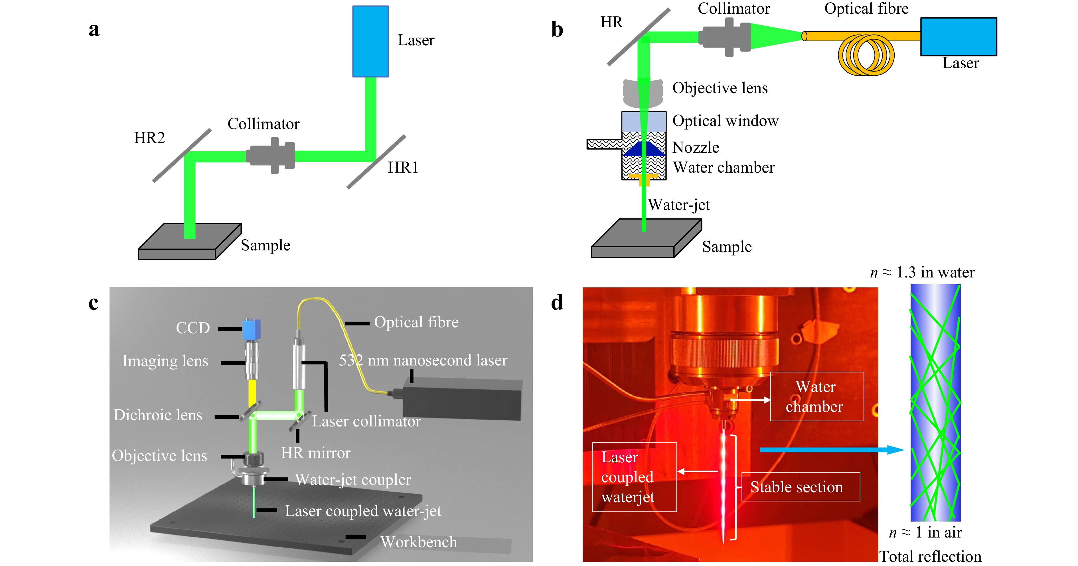
Fig. 1 Experimental set-up for laser processing. Schematic of the a conventional laser and b water-jet guided laser technology. c Diagram of the water-jet guided laser device. d Image of the laser coupled water-jet. The right inset image is the diagram of total reflection in the waterjet waveguide.
-
The two laser processing schemes were compared based on the microscopic morphology of the grooves. A carbide-reinforced RHEA sample with a nominal chemical composition of (NbMo)30Ta30W30C10 (at. %) was prepared for laser machining. The laser power of both methods was set at 5–15 W with an interval of 5 W, a scanning speed of 10 mm/s, and 10 repetitions of the grooving procedure. Fig. 2a shows an SEM image of the sample processed using CNL. At a low magnification, a small amount of slag or residual accumulation was observed; however, the groove had a distinct slope. The high-magnification image in Fig. 2b shows the microscopic morphology at the top of the groove. To illustrate the morphological changes in groove depth, the profile of the CNL groove is shown in Fig. 1c. Similarly, evident slag and residual sputtering projections were observed at the edge of the groove. The internal remelted layer had pores owing to rapid heating and cooling. The profile shows a clear V-shaped opening, indicating that the carbide-reinforced NbMoTaW RHEA sample processed by CNL had significant tapering, HAZ, and residual contamination. The SEM images of the grooves fabricated via femtosecond laser machining, as shown in Fig. S2, indicate that even ultrafast lasers cannot eliminate the generation of spatter and redeposits during the machining process. The elemental-mapping results presented in Fig. S3 and S4 indicate that these re-deposits are mainly composed of oxides. Therefore, when grooving the RHEA using CNL or a femtosecond laser, it is difficult to obtain a clean interface and low-taper groove.
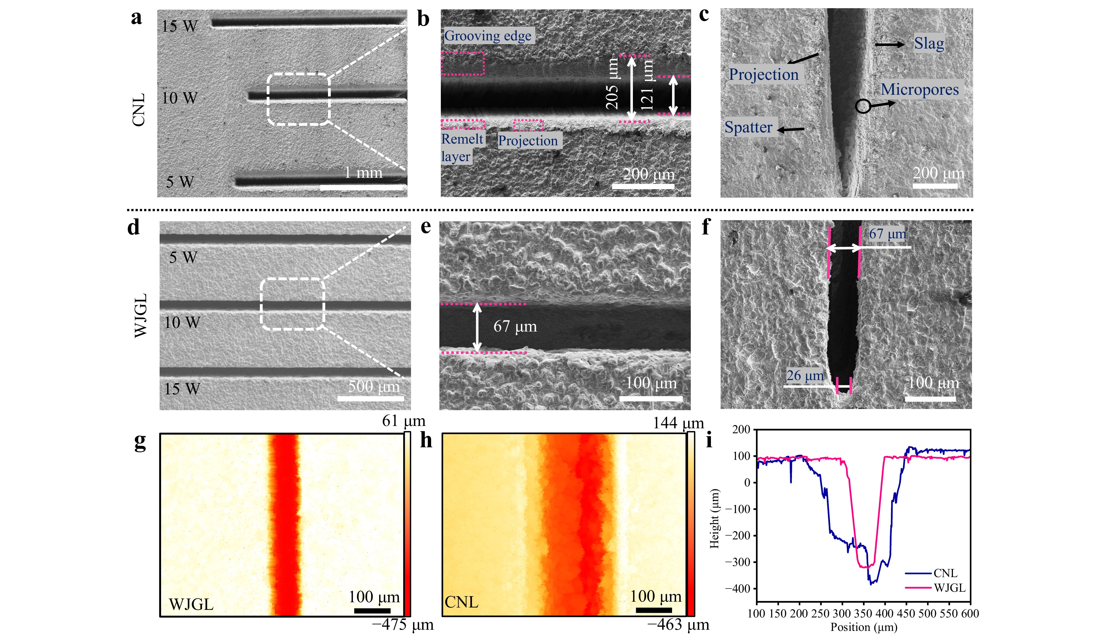
Fig. 2 Processing comparison of CNL and WJGL. a-c Grooving lines of CNL at different laser powers. d-f Grooving lines of WJGL at different laser powers. b, c and d, e were all processed under 10 mm/s, 10 W. g, h Roughness of grooves processed using WJGL and CNL. i Roughness profiles of grooves in g, h.
In contrast, the sample grooved by the WJGL exhibits a vertical profile and a neat surface owing to the uniform energy transfer, cooling, and flushing effect of the water jet, as shown in Fig. 2d-f. Fig. 2d illustrates the overall morphology of the grooves obtained under 5–15 W laser power, and the high-magnification surface morphology in Fig. 2e reveals clean and highly vertical cutting seam edges. Specifically, the groove fabricated under 10 W with a top width of 67 μm displays no excess slag. This indicates that the WJGL significantly eliminates excessive heat accumulation during the grooving process and generates a uniform depth evolution. Further analysis of the depth change based on the groove profile is presented in Fig. 2f. The approximately parallel groove reveals that the WJGL technology forms a groove without a visible tapered shape during grooving. Notably, no residual slags or projections were found on the two sides of the profile area, indicating that the WJGL technology has self-cleaning ability owing to high-speed jet flushing. However, the groove taper increases as the groove opening diameter decreases continuously near the bottom. This phenomenon arises from significant changes in the velocity and pressure of the water jet at the groove bottom.
The roughness data of the grooves fabricated using WJGL and CNL revealed remarkable differences in machining accuracy and quality. The contour plots presented in Fig. 2g, h show that CNL machining generates a larger groove opening and a distinct depth gradient during grooving. As illustrated in the surface roughness profiles of Fig. 2i, the CNL-processed sample exhibits a 256 μm wide groove opening, in contrast to the 67 μm of that fabricated using WJGL. This result is consistent with the SEM measurements. CNL-fabricated grooves are characterised by multiple depth gradients and rough groove bottoms, whereas WJGL-processed grooves feature smooth sidewalls and flat bottoms. These findings confirm that WJGL possesses significant advantages over CNL in terms of machining precision and quality.
The processing characteristics of the samples fabricated using the WJGL technology were investigated by adjusting the key machining parameters. To accentuate the differences in machining outcomes induced by speed, the scanning laser power was fixed to 20 W, whereas the scanning speed was varied from 5 to 25 mm/s in intervals of 5 mm/s. Fig. 3a displays the 3D interference profile of the grooves, and Fig. 3b presents the lateral contour data of the sample. The cutting depth data obtained at a scanning speed of 25 mm/s were excluded because the depth exceeded the detection range of the white-light interferometer. The depth variation can be attributed to the matching relationship among the scanning speed, water jet stability, and laser energy deposition rate in the material interaction zone. At low scanning speeds (5 and 10 mm/s), the prolonged laser-material interaction time caused excessive bottom disturbance of the water jet at the action point, which induced attenuation of the laser energy density and weakened the material removal efficiency. In contrast, excessively high scanning speeds (20 mm/s and above) resulted in insufficient laser energy deposition during a single scan, leading to inadequate material ablation and producing a rough machined bottom. A scanning speed of 15 mm/s corresponds to the optimal energy deposition rate for WJGL machining because at this speed, both the stability of the jet-material interface and a uniform ablation rate are ensured. The statistical roughness of the groove bottom also indicates a minimum roughness (0.0054 mm) at 15 mm/s, as shown in Fig. 3c. The average values of the bottom depths were –328.9, –402.4, –484.7, and –594.2 μm. Moreover, the grooving depth has a linear relation with scan speed at a fixed laser power; it can be fitted as y = –0.015x – 0.249 (mm), where y is the grooving depth and x is the scan speed. Therefore, appropriate parameter selection will balance the efficiency and material removal rate.
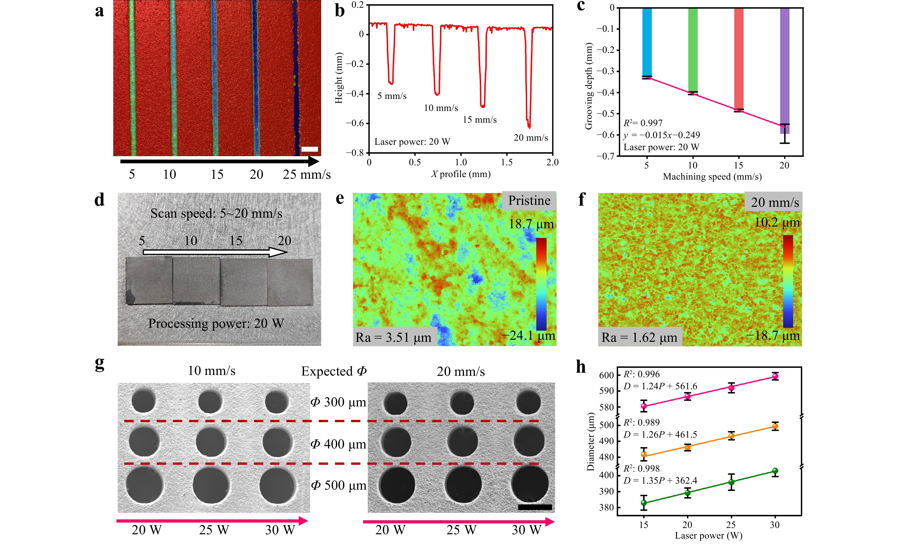
Fig. 3 Sliced samples processed using WJGL: a 3D interference profile of grooves under 15 W with speed varied from 5 to 25 mm/s; b height profile of grooves along the X direction; c roughness of groove bottoms in a; d image of sliced samples; roughness profiles of e pristine slice and f slice obtained using WJGL; g SEM images of drilled holes; h statistical diameters of drilled holes. Scale bars: 100 μm (Fig. 3a), 500 μm (Fig. 3g).
The overall morphologies of the WJGL-processed samples are presented in Fig. 3d. The surface of the 1 mm-thick RHEA sheet remained clean without any obvious processing residues. A comparison of the surface roughness values is shown in Fig. 3b, c. The surface roughness gradually decreased with higher scanning speed, and the lowest roughness of 1.62 μm was achieved at a speed of 20 mm/s. As shown in Fig. S5, the surface roughness decreased with increasing scan speed, even at different power levels. Notably, stripes were observed on the sample at a scanning speed of 5 mm/s. When the scanning speed reached 10 mm/s or higher, the striped processing marks almost disappeared. This might be caused by the higher scanning speed during the slicing of the RHEA, which led to multiple slicing and remelting cycles12.
Parameter optimisation is critical for improving the quality of WJGL-drilled holes. An orthogonal experimental parameter design was adopted to evaluate the drilling performance, with the target initial drilling diameters set to 300, 400, and 500 μm. Three replicate holes were drilled for each combination of parameters. The average value was calculated from three repeated measurements for each hole to minimise measurement errors. Fig. 3g presents SEM images of the drilled holes fabricated at laser powers of 20 and 30 W with scanning speeds of 10 and 20 mm/s. The statistical data in Fig. S6 indicate the correlation between the actual drilling diameter and the two key processing parameters (scanning speed and laser power). As illustrated in Fig. S6d, the actual drilling diameters exhibit similar standard deviations at different scanning speeds, whereas Fig. 3h displays a linear correlation between drilling diameter and laser power. The required compensation values were obtained via data fitting under different processing parameters to achieve the target drilling diameters. This result indicates that the variation in drilling diameter was predominantly determined by machining laser power rather than scanning speed.
The WJGL can achieve high-quality microchannel processing. The difference in radius between the top and bottom of the microchannel with an aspect ratio of 3.53 was only 4.6%. The drilling parameters of the test sample included a laser power of 20 W and a speed of 5 mm/s. The speed setting considered the motion accuracy of the workbench during microhole drilling. After the completion of drilling, the microhole with a length of 1 mm was evenly divided to obtain the test sample. Some areas were selected to obtain the surface profiles and roughness data at the top, middle, and bottom of the microholes. The top of the microhole was defined as the machining start position for water-jet-guided laser feeding. First, we collected and fitted the data for the sample surface profile. The contour graphs are shown from top to bottom in Fig. 4a-c. The fitted radii of the three positions were 296.98, 288.51, and 283.48 μm, as shown in Fig. 7d-f. The corresponding R2 values were 0.9997, 0.9996, and 0.997, respectively, indicating the high reliability of the fitted data and good agreement with the actual profile. Fig. 4g-i illustrate the roughness distribution along the Y direction as 0.312, 0.311, and 0.242 μm, with the average heights of the bottom profile being –0.1509, –0.1508, and –0.1512 mm, respectively. This surface has an average height fluctuation of less than 1 μm in a single direction. Therefore, WJGL can ensure high-quality characteristics when used for drilling low-roughness and high-flatness microholes.
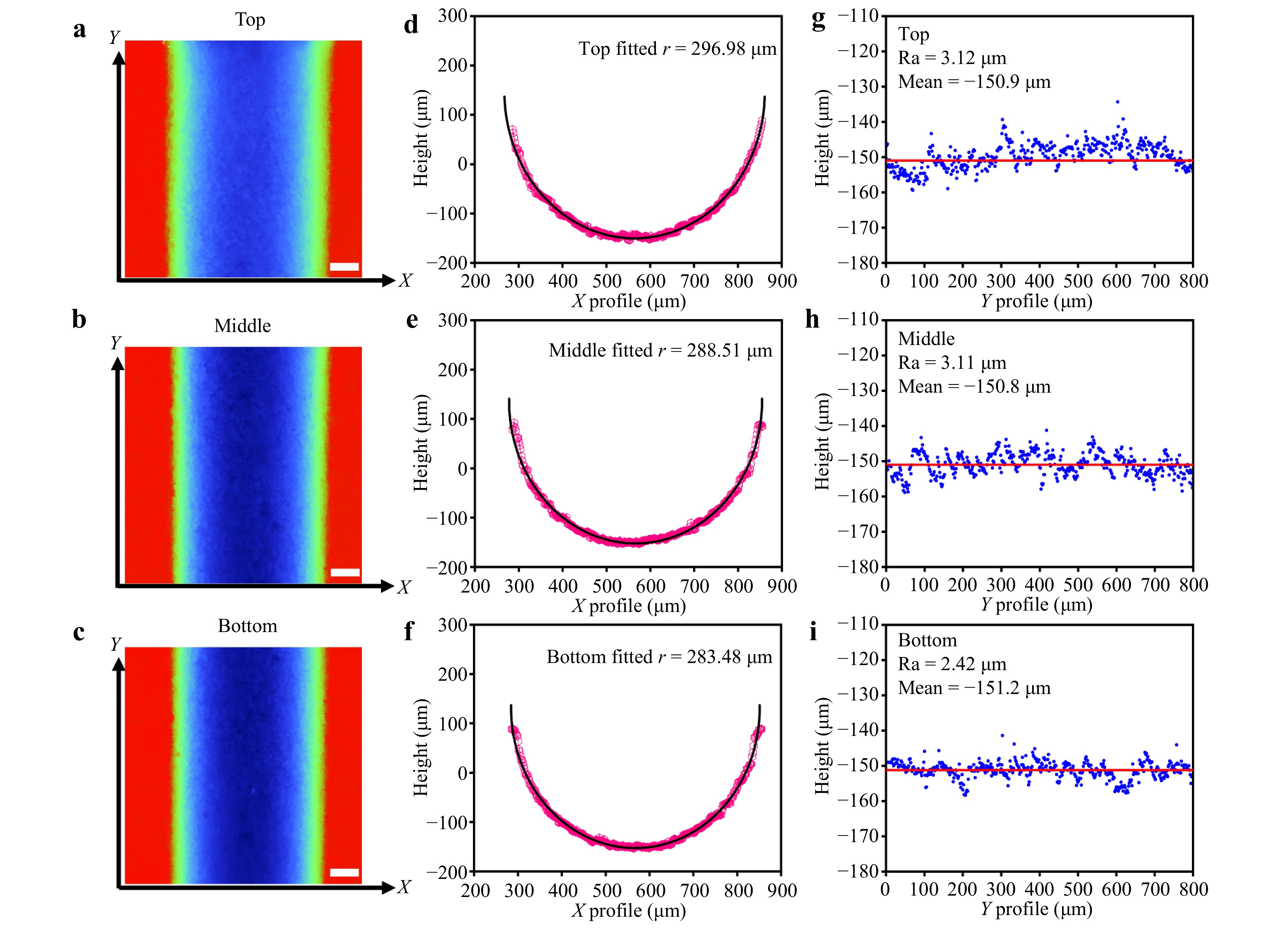
Fig. 4 Drilling quality assessment. Interference image and extracted data of the drilled microholes at the a-c top, d-f middle, and g-i bottom positions. Scale bars: 100 μm.
-
The structural changes in carbide-reinforced NbMoTaW during the machining of WJGL are crucial for optimising the technological process. The XRD patterns in Fig. 5a show the phase compositions of the CNL-processed and WJGL-processed surfaces before and after polishing. A body-centred cubic phase (BCC1) together with a hexagonal close-packed carbide phase (HCP) were detected on the polished surface, coinciding well with observations in the literature15. A series of extra diffraction peaks were observed in the CNL-processed sample, which were identified to be oxides. However, both the number and intensity of these oxide peaks distinctly decreased on the WJGL-processed surface. Interestingly, in addition to the oxides, a new set of diffraction patterns corresponding to a new BCC2 phase was observed on the WJGL-processed surface, as shown in Fig. 5b. This suggests that the remelted refractory elements would react with oxygen in the environment to form oxides. Simultaneously, considering the difference in melting temperature and their affinity with oxygen11,12, Nb and Ta were expected to undergo selective oxidation during WJGL processing, inducing the appearance of oxides on the processing surface. The lattice constants corresponding to BCC1 and BCC2 were calculated to be 3.218 and 3.158 Å, respectively. Then, owing to the cooling effect of the water jet, less active W and Mo with smaller radii were retained to form a new BCC2 phase but with a smaller lattice constant, shifting the diffraction peak to a higher angle as shown in Fig. 5b.
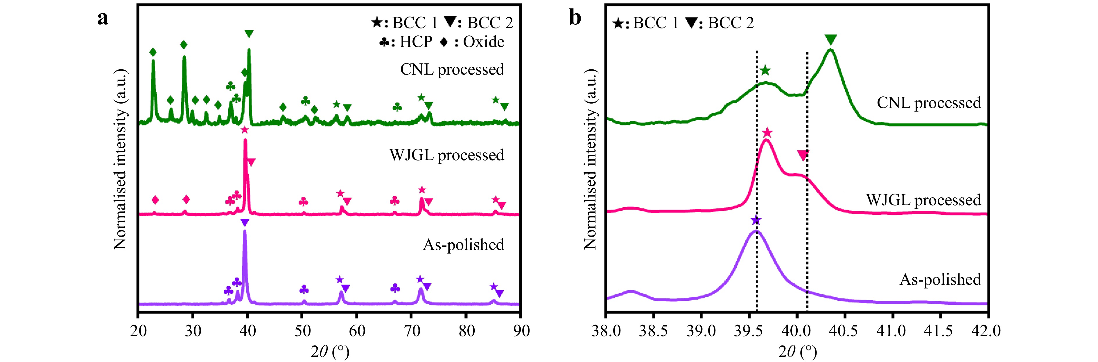
Fig. 5 a XRD patterns of WJGL sliced and surface polished samples. b Magnified range corresponds to BCC1 and BCC2.
Elements Nb Mo Ta W Melting point (℃) 2,468 2,610 3,000 3,380 Boiling point (℃) 4,927 5,560 5,427 5,900 Lattice parameter (Å) 3.301 3.147 3.303 3.165 Atomic radius (pm) 198 190 200 193 Formation enthalpies of oxide (kJ·mol–1) –1,899.5 –745.1 –2,045.9 –842.9 The phase and elemental distributions at the machining interface help guide the analysis of the process. The sliced profile exhibited a dual-phase structure with a single orientation in each phase. Moreover, the fractured area appeared to be generated at the boundary between the two phases. Fig. 6 shows the microstructure of the carbon-enhanced NbMoTaW after WJGL slicing. Fig. 6a-c show the cross-sectional SEM image, corresponding EBSD phase map, and inverse polo figure (IPF) of the WJGL-processed sample. The intergranular areas exhibit a eutectic-like morphology, as shown in Fig. 6a, consistent with previous observations15, and the EBSD phase map in Fig. 6b confirms the existence of both the BCC phase and HCP carbides. However, some dark-contrast phases, marked by white lines, were observed in the areas close to the processing surface. These could not be indexed as either the BCC or HCP phases (Fig. 6b); thus, they were regarded as oxides. Meanwhile, some cracks propagated along the interface between the oxides and the matrix. Additionally, the IPF image in Fig. 6c further suggests the possible change in crystallographic orientation for both the BCC phase and carbides. Therefore, these areas are likely the WJGL processing induced affecting zone, possessing a width ranging from 5 to 20 μm. This assumption was further verified using elemental distribution. The elemental distribution images in Fig. 6d-f and Fig. S7 indicate that Ta and Nb were segregated as carbides, whereas W and Mo were partitioned into the BCC phase.
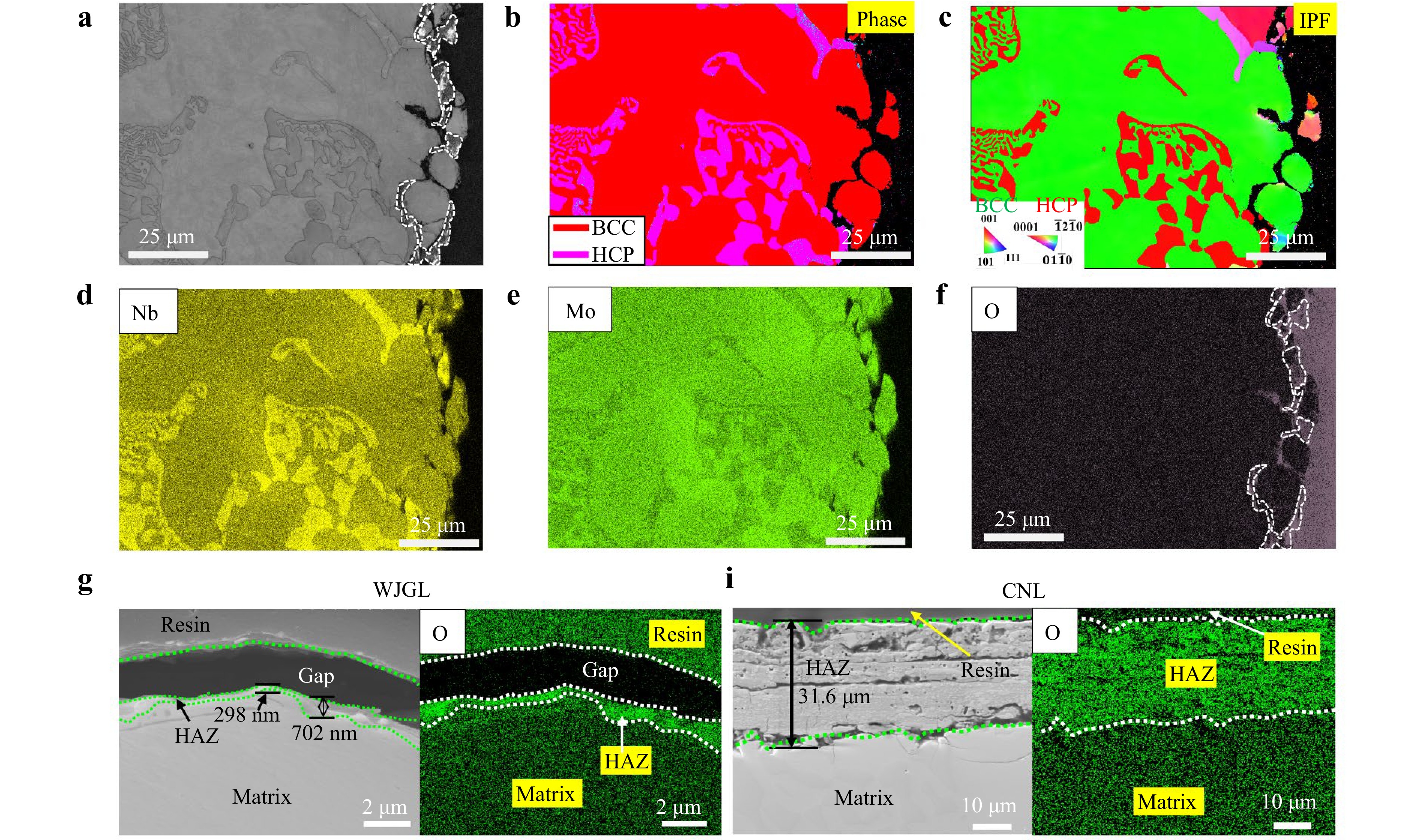
Fig. 6 SEM images and mapping result of the WJGL processed interface and material matrix. a SEM image of the slice profile with lower magnification. b, c Phase and IPF map figures of a. d-f Element mappings of the slice profile. g-i Element mappings at HAZ corresponding to the WJGL and CNL processed samples.
Notably, oxygen was concentrated in the dark-contrast phase, and the formation of oxides was confirmed through oxygen mapping and point scanning. Fig. 6g reveals that the HAZ width of the WJGL-processed samples ranged from 298 to 702 nm, with the oxygen content in the HAZ (marked by the green dashed line) ranging from 5.9% to 25.1%, as shown in Fig. S8. These values are significantly higher than the average oxygen content of 3.7% in the matrix. The formation of oxides in the HAZ of the CNL-processed samples was verified from the mapping results shown in Fig. 6i. The combined line scanning (Fig. S9) and mapping measurements confirmed that the HAZ width of the CNL-processed samples reached 31.6 μm, indicating that the HAZ width on the surface of WJGL-processed samples was less than 1% of that of CNL-processed ones. In summary, an ultrathin HAZ was formed on the surface of the WJGL-processed samples, which was significantly thinner than that of the CNL-processed samples.
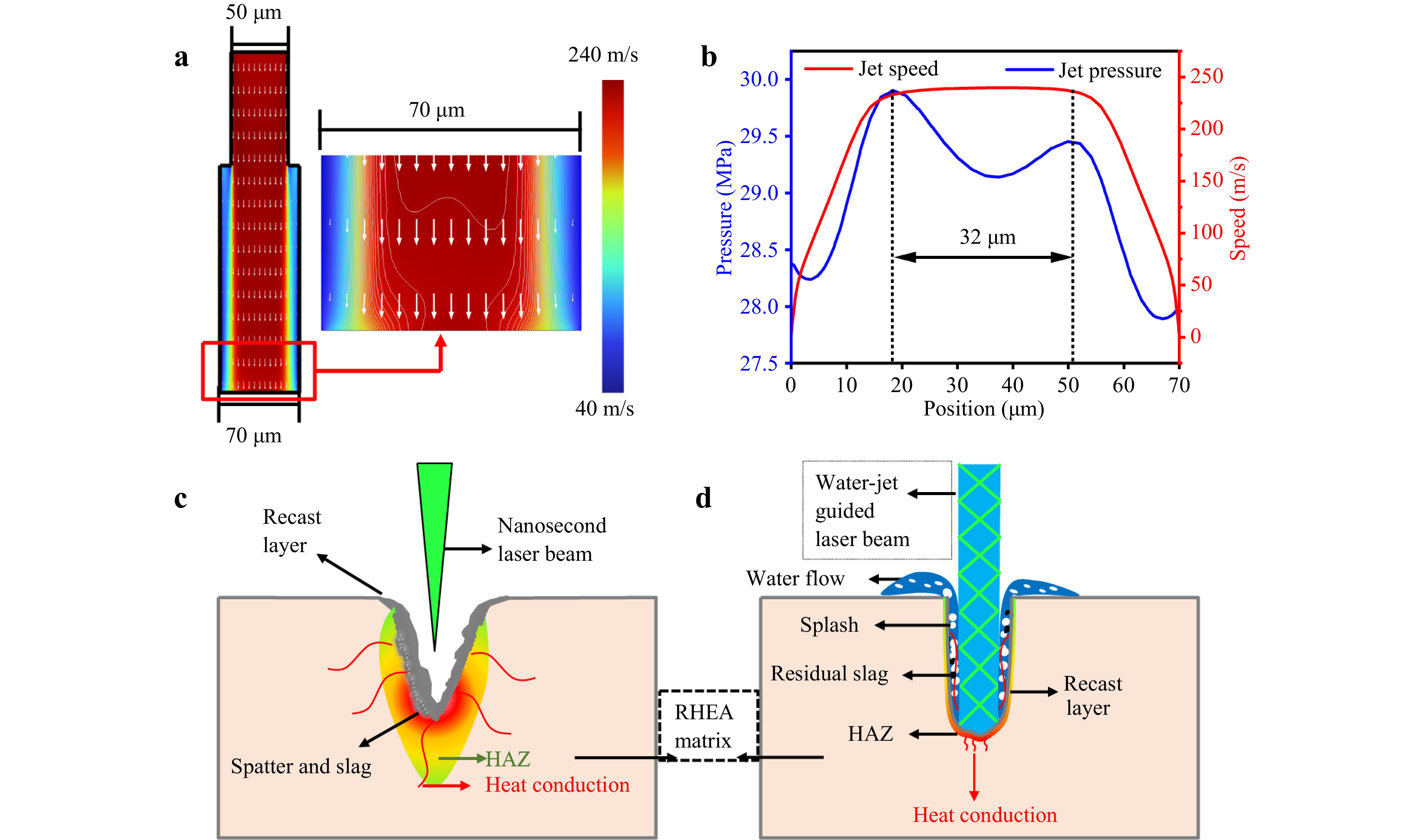
The processing mechanism was proposed based on an analysis of the simulation and experimental results. The evolution of the jet velocity distribution within the microchannel led to non-zero taper processing. The clean processing surface was the result of flushing, the cooling effect of the water jet, and the high melting point of NbMoTaW (C10). The flow behaviour of the water jet after entering a vertical channel at a certain depth was verified through a flow field simulation. In the simulation, the channel width was set to 70 μm and the height to 200 μm. The high-speed water-jet with a diameter of 50 μm entered the channel and caused lateral diffusion, as shown in Fig 7a. The geometric model and boundary conditions are explained in Fig. S10. The incident velocity at the jet edge decreased with the appearance of lateral diffusion. The velocity decrease gradually expanded towards the centre of the jet as the channel depth increased. The range of velocity reduction at the jet edge reached a maximum near the bottom of the channel. The water jet produced four lateral pressure intervals at the bottom of the channel within a range of 27.7–30 MPa as shown in Fig. 7b. The distance between the two pressure peaks was 32 μm, which was close to the 26 μm obtained from the cross-sectional result of the SEM shown in Fig. 2f. Some interesting phenomena occurred after extracting the relevant pressure and velocity data. The jet pressure changed by less than 10%, but the vertical velocity changed from 240 m/s at the pressure peaks in the centre to 40 m/s towards the channel wall. After reaching the bottom of the channel, the jet continued to release pressure downward. The channel centre tended to generate large-depth material removal because the stable waterjet core maintained continuous laser energy transfer.
Based on the simulation results, we propose machining mechanisms utilising CNLs and WJGLs. As shown in Fig. 7c, the CNL produced a typical V-shaped notch owing to the Gaussian energy distribution of the beam cross section. Because of the rapid melting and recrystallisation of NbMoTaW after reaching its melting point, a large amount of spattered particles and slag were generated at the opening and profile of the groove. The machining mechanism of the WJGL is shown in Fig. 7d. Similar to traditional fibres, the laser energy is uniformly distributed in the water jet. Consequently, the laser power guided by the water jet could be uniformly transferred to the NbMoTaW matrix. A clean surface is formed because the spatter and slag produced during material removal are washed away by the water flow. The HAZ is significantly reduced even though the melting point of NbMoTaW is approximately 3,000 °C. Moreover, owing to the multiregion distributions of speed and pressure generated when the jet enters the processing area, the energy of the jet edge is dissipated as the machining depth increases. The edge energy dissipation of the water-jet-guided laser induces an uneven feeding speed along the lateral direction at the channel bottom.
-
Drilling and pattern machining are crucial in prospective engineering applications. WJGL can potentially process RHEA for mechanical components at the millimetre and even micrometre scales, as shown in Fig. 8. We produced an ultralow-taper microhole array on an NbMoTaW sheet. Microholes with diameters of 300, 400, and 500 μm were each processed 10 times, as shown in Fig 8a. The relevant taper values were 0.0144°, 0.0200°, and 0.0143°, respectively, as shown in Fig. S11. Moreover, the drilled microchannels exhibited reliable repeatability and consistency, as shown in Fig. 8b, c. Finally, we demonstrated the machining ability of the WJGL, as shown in Fig. 8d-f. A size comparison of Fig. 8e, f is shown in Fig. S12. The measurement results of these components indicate the high-precision processing potential of the WJGL, particularly for the precise angle and curvature processing requirements for RHEA.
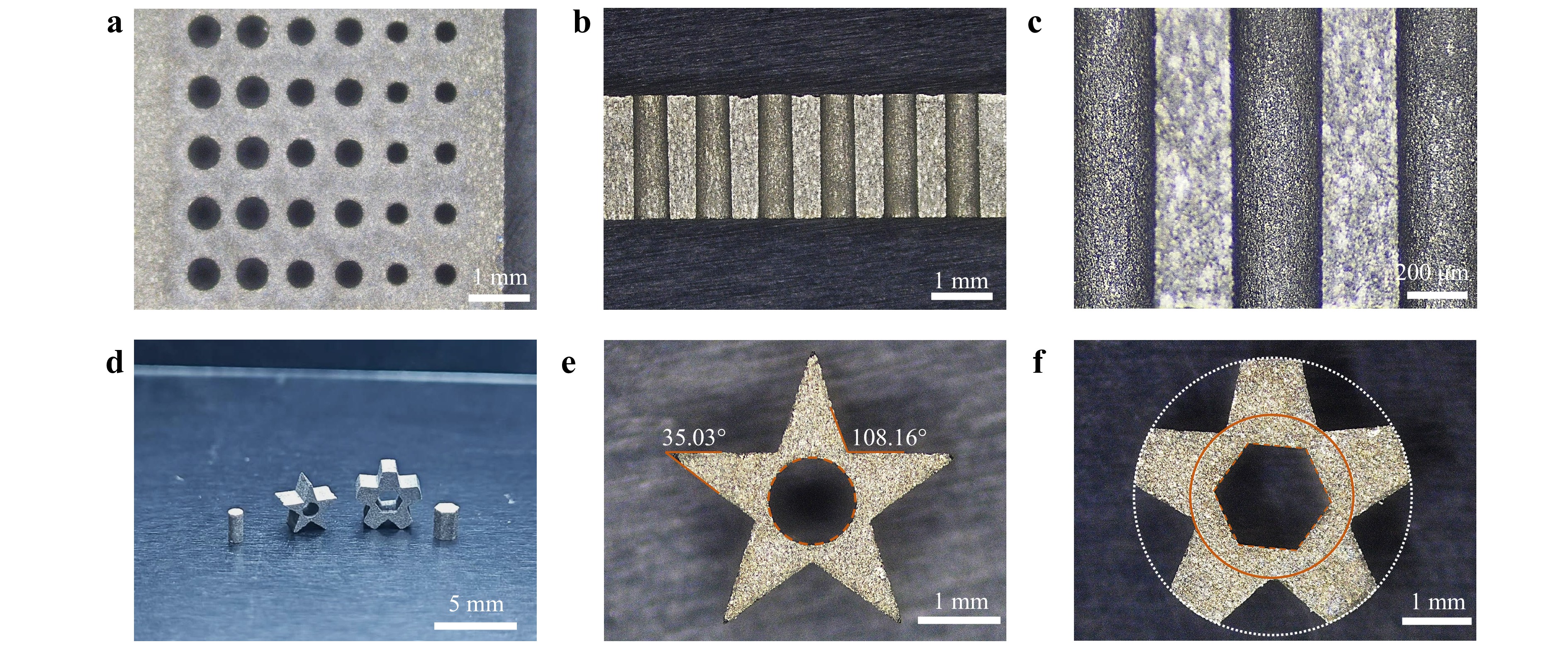
Fig. 8 Hole array and pattern machining results. a Optical image of the hole array on NbMoTaW sheet. b, c Profile of drilling channels at low and high magnification. d-f Optical images of the pattern machined samples.
-
This work systematically investigated using WJGLs for the precision micromachining of carbide-reinforced NbMoTaW RHEAs, with CNLs as the control. WJGLs exhibited superior machining performance, fabricating neat, low-taper grooves with clean interfaces, whereas CNLs produced V-shaped grooves with slag residue. For WJGL drilling, the machined diameter was dependent on the laser power rather than the scanning speed. XRD and EBSD characterisations revealed that the WJGL induced a new BCC2 phase and an ultrathin HAZ (298–702 nm) on the RHEA surface. Based on flow field simulations, we proposed a WJGL machining mechanism and clarified that a slight taper was caused by changes in the jet flow field. Finally, the WJGL was used to successfully fabricate ultra-low-taper microhole arrays (0.014°) and complex patterns, which verified its significant potential for engineering applications. This study provides a reliable route for machining hard-to-process RHEAs and other refractory materials, and it paves the way for the manufacture of RHEAs in the aerospace and nuclear energy fields.
Future exploration of the coupling mechanism between the water jet and the laser will help improve the coupling power and introduce ultrashort lasers to improve processing efficiency and reduce thermal effects. Additionally, the development of in situ characterisation techniques will assist in exploring the processing mechanism of WJGLs on RHEA, enabling precise control of processing parameters and further improving the processing quality and efficiency of producing complex and precise components with RHEA.
-
This work was supported by the National Key Research and Development Program of China (grant number 2023YFE0200200), and the National Natural Science Foundation of China (grant number U2141205, 52171096).
Precise micromachining of carbide reinforced NbMoTaW refractory high entropy alloy with ultrathin heat affected zone using water-jet guided laser technology
- Light: Advanced Manufacturing , Article number: 99 (2026)
- Received: 26 September 2025
- Revised: 09 June 2026
- Accepted: 10 June 2026 Published online: 22 August 2026
doi: https://doi.org/10.37188/lam.2026.099
Abstract: Refractory high-entropy alloys (RHEAs) have attracted considerable interest owing to their excellent mechanical strength and thermal stability. However, their inherent brittleness and low thermal conductivity pose significant challenges for high-precision micromachining at room temperature. Conventional nanosecond lasers (CNL) and wire-electrode cutting inevitably cause severe thermal damage and reduce machining quality. In this study, water-jet guided laser (WJGL) technology was utilised for the precision machining of a carbide-reinforced NbMoTaW RHEA. Benefiting from synergistic ablation, cooling, and debris removal effects, WJGLs enable a much cleaner machining interface with minimal spattering compared with CNL and femtosecond lasers. Notably, WJGLs reduced the heat-affected zone to 298 nm, which was ~99.1% lower than that of the CNL. A minimum drilling taper of 0.014° was achieved, indicating ultrahigh micromachining precision. The material removal mechanism and microstructural evolution were elucidated. This study provides a reliable approach for the precision manufacturing of hard-to-process RHEAs.
Research Summary
Water-Jet Guided Laser Enabled Precision Manufacturing of High-Entropy Alloys
Refractory high-entropy alloys (RHEAs) have attracted considerable interest owing to their excellent mechanical and thermal properties. However, their inherent brittleness and low thermal conductivity pose significant challenges for high-precision micromachining at room temperature. Conventional nanosecond lasers (CNL) and wire-electrode cutting inevitably cause severe thermal damage and reduce machining quality. In this study, water-jet guided laser (WJGL) technology was utilised for the precision machining of a carbide-reinforced NbMoTaW RHEA. Benefiting from synergistic ablation, cooling, and debris removal effects, WJGLs reduced the heat-affected zone to 298 nm, which was ~99.1% lower than that of the CNL. A minimum drilling taper of 0.014° was achieved, indicating ultrahigh micromachining precision. The material removal mechanism and microstructural evolution were elucidated. This study provides a reliable approach for the precision manufacturing of hard-to-process RHEAs.
Rights and permissions
Open Access This article is licensed under a Creative Commons Attribution 4.0 International License, which permits use, sharing, adaptation, distribution and reproduction in any medium or format, as long as you give appropriate credit to the original author(s) and the source, provide a link to the Creative Commons license, and indicate if changes were made. The images or other third party material in this article are included in the article′s Creative Commons license, unless indicated otherwise in a credit line to the material. If material is not included in the article′s Creative Commons license and your intended use is not permitted by statutory regulation or exceeds the permitted use, you will need to obtain permission directly from the copyright holder. To view a copy of this license, visit http://creativecommons.org/licenses/by/4.0/.

 DownLoad: