




-
In conventional refractive microscope objective designs, correcting chromatic aberrations, especially lateral color over a large field of view (FOV), remains a challenge1. Commercial microscope objectives are typically corrected for two or three wavelengths within a given spectral band of light, which is accomplished by combining lenses with different optics powers and material dispersions to bring the desired wavelengths into focus at a single plane. However, refractive objectives are less suitable in imaging techniques that integrate multiple microscopy modalities or require the use of widely separated wavelengths. This is particularly true in nonlinear optical (NLO) microscopy, a powerful tool for biomedical imaging2–11, which often involves excitation and emission wavelengths that are spectrally distant, demanding effective chromatic correction across a broad spectral range. Besides the required chromatic aberration correction already mentioned, refractive elements introduce group delay dispersion that broadens the excitation pulses used in NLO imaging, thus reducing the generated signal strength. In contrast, reflective optics are inherently achromatic and free of group delay dispersion, so an all-reflective objective would be a breakthrough for NLO microscopy.
A relatively simple all-reflective objective already exists in the Schwarzschild form12, but it suffers from a large on-axis obscuration from the concentric arrangement of its two mirrors. The obscuration reduces image contrast13 and the total throughput of the objective. To address these issues, an unobscured alternative is desired. Such a solution can only be realized, however, by straying from traditional rotational symmetry. Then, to effectively correct the resulting rotationally variant aberrations, the use of more complex surface shapes, such as freeform optics14,15, is necessary.
Prior studies in all-reflective optical microscopy have investigated the use of spherical mirrors arranged in an off-axis configuration for beam expansion and a scan relay, while incorporating commercially available rotationally symmetric reflective objectives16,17. In the field of unobscured reflective microscopy, a freeform reflective objective with a 0.4 numerical aperture (NA) was developed to showcase a novel design strategy for wide-field aplanatic systems18. Another effort explored a fully reflective microscope system employing a 0.5 NA objective that utilized freeform optics throughout its design19. Additionally, a 0.33 NA objective tailored for strip-field imaging was created by building on a base of rotational symmetry20. Finally, a low-NA zoom microscope objective was developed for search and inspect functions21. Our preceding study22 described the optical design methodology used to conceptualize and optimize an all-reflective microscope objective that surpassed existing unobscured solutions in both NA and packaging size. That work evaluated several front-group folding configurations, comparing each system’s nominal optical performance, packaging constraints, and sensitivity characteristics in a theoretical environment. A comparison of the prior art and our system for relevant system parameters is shown in Table 1.
Publication NA FOV (mm) Working distance*
(mm)Package size
(L)Wang and Zhu18 0.40 2 × 2 0** 1.8 (inc. tube lens) Peterson et al.19 0.53 0.75 (radial) 9 1.1 (inc. housing) Wang and Zhu20 0.33 10 × 1.5 8** 0.75** Wang and Zhu21 0.2–0.3 1.5 × 1.5-1 × 1 0** 0.19** Current design 0.65 0.3 × 0.3 0.5 0.16 *Working distance is defined as the distance between the plane of the image and the plane of the nearest mechanical feature. **Parameter value was not explicitly given in the publication and was instead estimated from a diagram or other provided data. Table 1. Specification comparison between the current proposed system and prior art.
Building upon the foundational design concepts of our previous study22, this present work serves as a transition from a theoretical study to a physical demonstrator by introducing additional design phases focused on manufacturability that yielded an objective suitable for fabrication. In parallel, a mounting scheme for the optics was conceived and a mechanical housing was designed and fabricated to precisely align and hold the optical elements. To facilitate the ultra-sensitive alignment necessary, an assembly station was constructed that enabled multiple at-assembly compensators to be used to recover the system performance after mounting the optical elements. The freeform optics were diamond-machined and subsequently measured using an optical coordinate measuring machine (CMM). The finished optics were then installed into the objective housing, and first light was obtained by imaging a resolution target and a biological sample.
-
In our previous publication on this topic22, we detailed the process for determining the ideal objective mirror geometry and then translating that concept into a real optical design. That work concluded that a six-mirror design, shown in Fig. 1, outperformed the competing five-mirror design in terms of nominal optical performance, packaging efficiency, and tolerance sensitivity. This current manuscript describes the design-for-manufacture evolution of the six-mirror design concept that was tailored to the application space of NLO biological imaging.
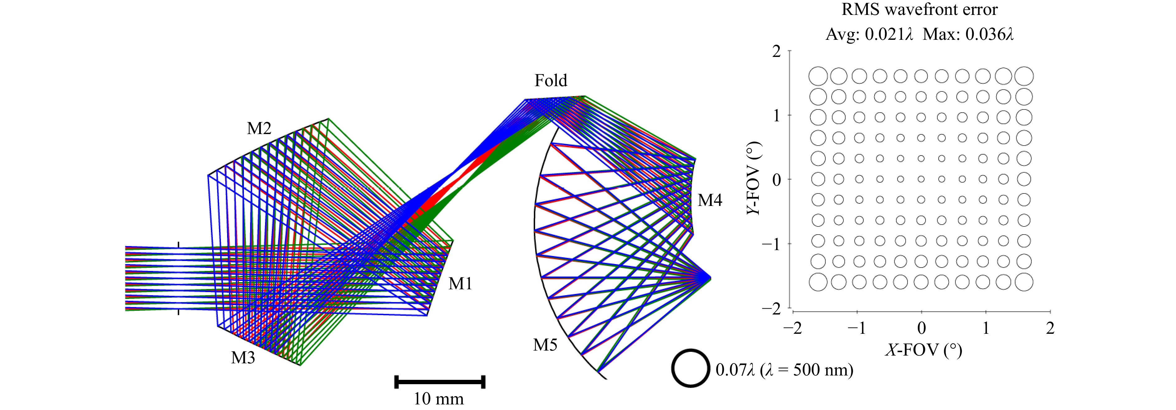
Fig. 1 Conceptual design in our previous paper on this topic22. M2, M4, and M5 are freeform, M1 and M3 are spheres, and the fold is flat. This design serves as the starting point for the design-for-manufacture of an all-reflective microscope objective tailored for NLO biological imaging.
-
In the design-for-manufacture targeted at NLO biological imaging, the first critical requirement addresses the need for a coverslip atop the sample. Given the wide spectral range of the targeted imaging techniques (0.5–6 µm), a calcium fluoride coverslip was selected to ensure transmission across the full wavelength range. Though the coverslip is a simple component, it has a significant impact on the system aberrations. While the monochromatic aberrations introduced by the coverslip can be compensated by reflective objective design, its chromatic impact cannot be compensated for in an all-reflective configuration (unlike in refractive objectives, where its dispersion can be accounted for). The chromatic aberrations generated by the coverslip scale with the thickness of the coverslip, so minimizing the thickness is important. Although thickness options for commercially available calcium fluoride coverslips are limited, we successfully sourced 0.35 mm-thick coverslips for this application that satisfied our needs.
Then, following preliminary opto-mechanical design work on the housing, it became clear that the starting point objective's working distance (WD) needed to be increased to accommodate realistic component thicknesses. Specifically, a 4-mm M4 substrate thickness, a 0.75-mm thickness of the mounting wall for M4, and the 0.35-mm coverslip must be accounted for when determining the WD. The conceptual design had a 2-mm WD, defined as the axial distance between the image plane and the nearest optical surface. To give the user an 0.5-mm effective WD (comparable to other high-NA objectives), defined as the axial distance between the sample plane and the nearest mechanical surface, the original 2-mm WD needed to be extended to 5.6 mm. This substantial increase in the WD considerably stresses the design as it increases the beam size at M5, making it an ultra-fast mirror (faster than F/0.4). Let us note here that a fast M5 not only degrades the nominal system performance but also increases its sensitivity to manufacturing and alignment tolerances.
Additionally, the preliminary opto-mechanical analysis revealed that M4 could not feasibly serve as a compensator during assembly (as had been theoretically modeled) due to insufficient space for the fixturing that would be required to adjust its position. Lastly, the baseline sensitivity analysis of the previous work only included basic astigmatic surface errors. For a more representative assessment of the as-built system, a comprehensive figure tolerance analysis was conducted and will be reported in Section 2.4. Furthermore, the prior analysis assumed ideal at-assembly compensation, with infinite precision. Thus, the sensitivity analysis in this design-for-manufacture stage incorporates “lock-down error” associated with the compensator adjustments and devises an assembly plan that accounts for compensator limitations. To allow for use within an existing commercial microscope frame, the input and output optical axes are required to lie along the same axis. Accounting for these considerations, the specifications of the design-for-manufacture system are shown in Table 2.
Parameter Unit Specification Wavelength range nm 500−6,000 Numerical aperture − 0.65 Image size mm 0.3 × 0.3 Working distance mm 5.6 Effective working distance mm 0.5 Entrance pupil diameter mm 7 Input/Output optical axes − Coaxial Back focal plane location − Accessible RMS wavefront error waves < 0.035 (nominal) at λ = 500 nm Distortion % < 2 Coverslip material − Calcium fluoride Coverslip thickness mm 0.35 System axial length mm 50−70 System half width mm < 20 (cylindrical radius)
< 12 (one-sided bulge from cylinder)Table 2. Specifications for the all-reflective microscope objective that includes design-for-manufacture considerations
-
With the specifications provided in Table 2, we performed an initial series of system optimizations following an aberration-based optimization strategy15. While the nominal wavefront error (WFE) of the designed system was acceptably low, a preliminary sensitivity analysis revealed that it was unreasonably sensitive to assembly errors, rendering it impractical for manufacture. Consequently, we incorporated as-built performance into the optimization merit function.
The method that was found to give the most robust as-built performance is based on the desensitization strategy introduced by Fuse23 for rotationally symmetric optics. In this approach, the system is modeled with multiple configurations/zooms. The base configuration represents the nominal design, while each additional configuration is a replica of the base configuration modified with mirror alignment perturbations. The perturbations were applied to the six rigid body degrees of freedom (X, Y, Z, tip, tilt, clocking) for each mirror. The perturbations were generated randomly within each respective tolerance range with a uniform probability density function. We found that using 20 additional configurations yielded a good balance between optimization speed and desensitization impact. The base design parameters for each perturbed replica are “picked up” from the base configuration, meaning that if there are any changes made to the base configuration, those changes propagate to each replica, but the perturbations remain applied. Subsequently, the base configuration is optimized while all configurations contribute to the optimization merit functions. Since the additional configurations are tied to the base configuration, any changes to the parameters of the base configuration during optimization are automatically and continuously applied to each additional perturbed configuration. Also, because the perturbations of the additional configurations remain fixed, the optimizer converges on a solution that not only performs well nominally but also maintains acceptable performance across the perturbed configurations. The system was optimized in CODE V using the built-in wavefront error merit function with uniform weighting across the FOV and for each perturbed configuration. The result is a design that is desensitized to manufacturing errors.
Fig. 2 shows a comparison of the predicted as-built performance at an intermediate phase of this design between a system that was optimized prioritizing only the nominal performance and a system that was optimized using the desensitization method. As expected, the nominal performance is highest for the nominal-performance-prioritized system, but after assembly tolerances are applied, the desensitized version has roughly 2x better predicted as-built performance. Interestingly, this desensitization optimization facilitated the use of higher-order Zernike polynomials (Z37–Z64, in Extended Fringe ordering) in the mathematical description of M4 and M5, which were critical for achieving the requisite correction with the increased WD. Without the desensitization optimization methods, the higher-order polynomials only served to improve the nominal performance and always made the as-built performance worse. The desensitization approach presented here is central to the development of a methodology aimed at design-for-manufacture.
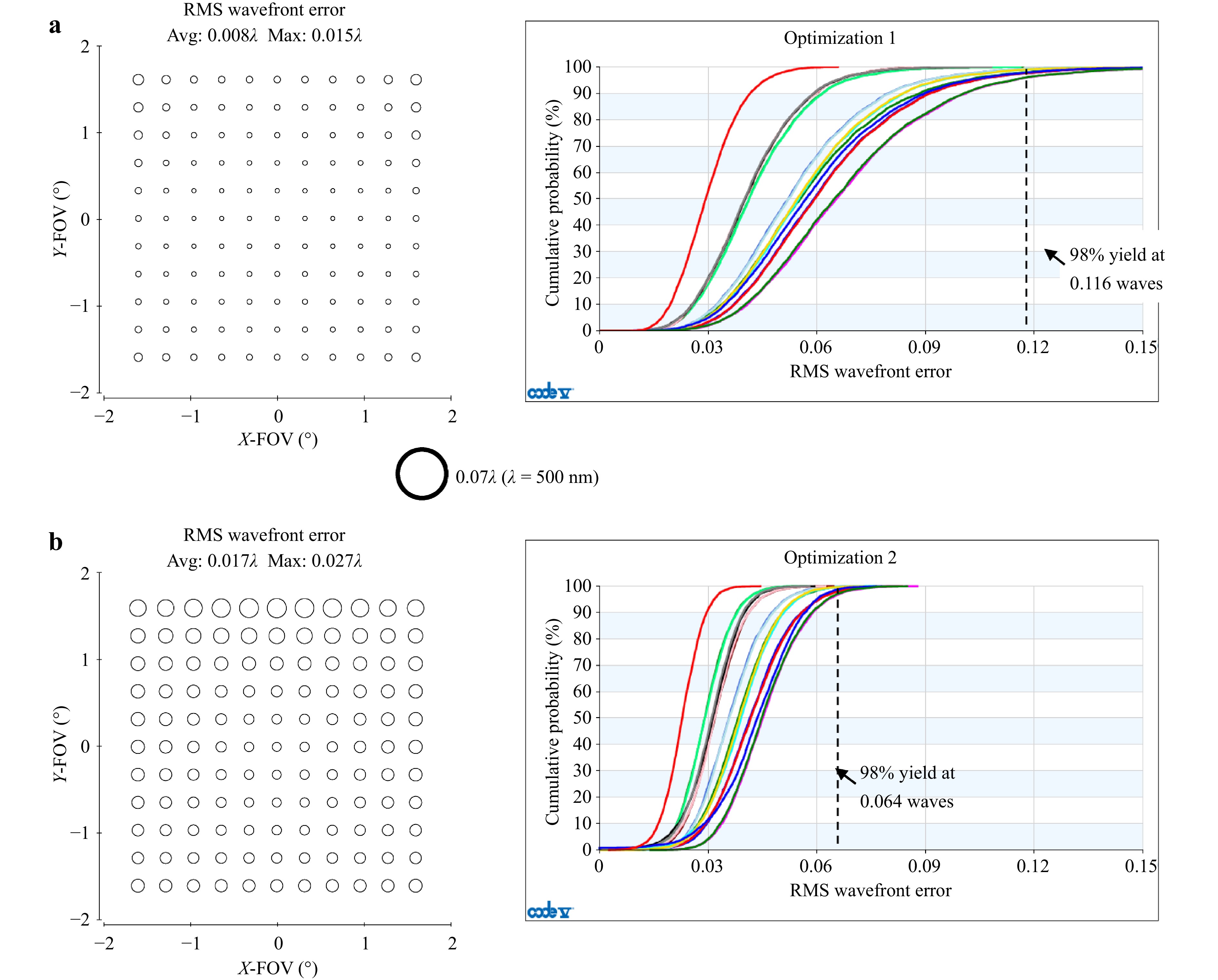
Fig. 2 Desensitization comparison. (left) Full-field display showing the nominal RMS WFE and (right) percent-yield plots indicating the predicted as-built performance at regions across the full FOV for a a system optimized without desensitization and b a system optimized with desensitization at an intermediate phase in the design process.
Integrating the aforementioned design and optimization strategies, we ultimately converged on the optical design shown in Fig. 3. The finalized design comprises three freeform mirrors (M2, M4, and M5), two spherical mirrors (M1 and M3), and a single fold flat. The freeform surfaces were mathematically defined using Zernike polynomials, represented by the Extended Fringe ordering scheme in CODE V, up to the 64th term. This parameterization provided the necessary degrees of freedom (DOFs) to achieve the required aberration correction, particularly considering the high NA, the increased working distance, and the presence of the coverslip.
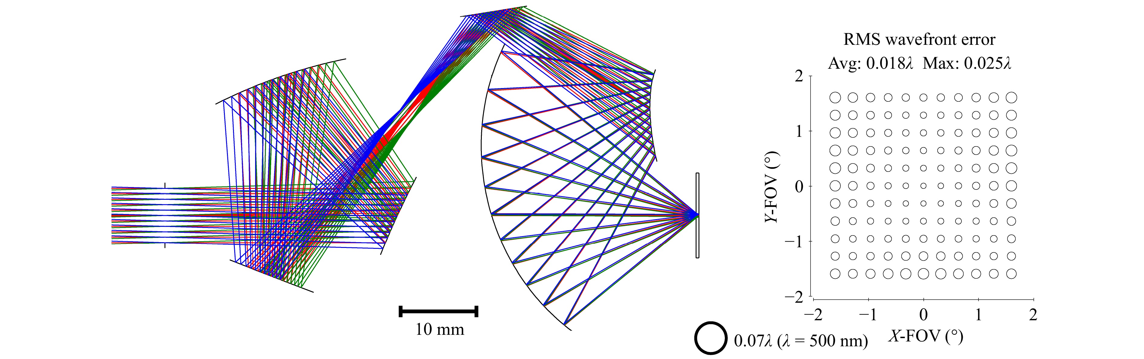
Fig. 3 The final optical design and its nominal RMS WFE. The performance is better than the diffraction limit, providing a useful buffer for manufacturing errors.
-
An essential consideration for off-axis reflective systems is the potential presence of specular stray light. While all mirror geometries are subject to low intensity diffuse stray light from surface scattering, specular stray light is uniquely present in some mirror geometries, and its high intensity can cause problematic hotspots in the image. To assess this source of stray light, we analyzed possible ray paths that propagate from image space to object space through specular reflections from mirrors in an unintended sequence. The system was modeled using nonsequential raytracing software with a Lambertian source placed near the image plane. Rays were emitted in all directions from this source. A field stop was placed at the intermediate image plane between M3 and the fold, which played a critical role in blocking stray light paths. The analysis showed that only rays that reflected from the mirrors in the intended order were detected in object space, meaning that there are no stray specular paths for this mirror arrangement, as shown in Fig. 4.
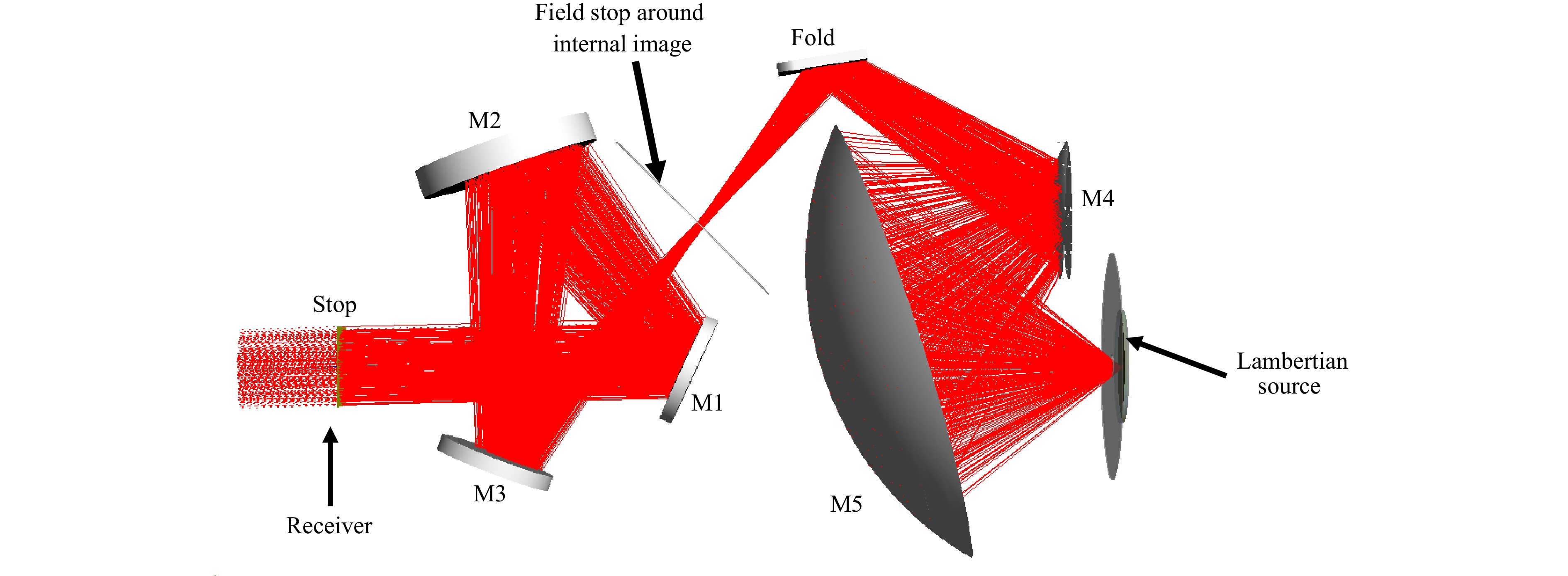
Fig. 4 Non-sequential raytrace of the system using a Lambertian source located near the image plane. A receiver is located at the entrance pupil. Only rays that follow the intended reflection path (colored red) are incident on the receiver, indicating there are no stray specular reflections paths.
-
The as-built performance of the final design was evaluated using a Monte Carlo analysis whereby the assembly and fabrication tolerances were applied to the system in a randomized fashion, while staying within the prescribed tolerance range, and the resulting performance of the system was calculated. This process was repeated numerous times to generate statistical insights into the expected as-built performance. Based on our previous work, we anticipated the need for an at-assembly compensator to recover performance losses due to manufacturing errors in both the optical surfaces and the positioning of the optics. An at-assembly compensator is an optic whose position can be adjusted in the final stages of the assembly, after the fixed elements have been mounted. In the final optical design, both M4 and M5 were identified as effective candidates for compensation; M1, M2, and M3 were found to be too slow to effectively generate the compensating aberrations needed. However, in the optomechanical housing design, the mounting of M4 has a direct impact on the effective working distance, so it must be packaged as compactly as possible against a sidewall, as shown in Fig. 5. As a result, there is not enough space for it to be a practical, actively aligned compensator. Thus, M5 was the only effective compensation candidate for positioning and surface errors.
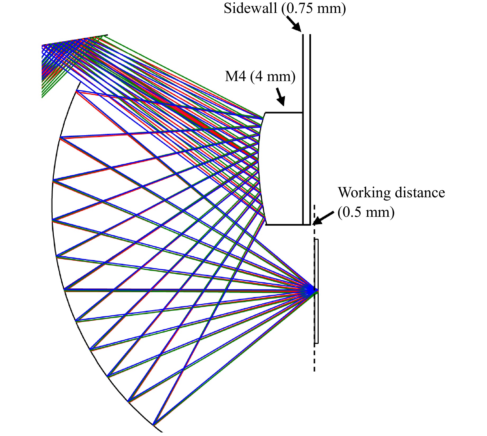
Fig. 5 . Thickness build-up near image plane. After adding real thickness to the rear side of M4 and giving it a sidewall to be mounted upon, there is 0.5 mm of clearance remaining between the glass cover slip and the mechanics, which is considered to be the effective working distance. Due to the limited space around M4, it cannot serve as the at-assembly compensator.
Each mirror possesses six degrees of possible displacement from nominal due to manufacturing errors (X, Y, Z, tip, tilt, clocking). To model potential figure errors of the freeform mirrors, perturbations were applied to their Zernike coefficients, specifically Z4, Z5/6, Z7/8, Z9, Z10/11, Z12/13, and Z14/15. The spherical and flat elements were modeled with standard power and irregularity tolerances. The complete list of tolerances is shown in Table 3. Although the tolerances are tight, they are manufacturable using precision techniques such as diamond-machining. The resulting percent-yield curves, shown in Fig. 6a, indicate that the as-built performance approaches the diffraction limit at the shortest operating wavelength of 500 nm. However, this analysis assumes that the M5 compensator can be moved with infinite precision and be locked in place without it moving–conditions that are idealized and unlikely in practice. For M5 compensation, lock-down errors include the precision of the stage actuator positioning and the shrinkage of the bonding agent used to hold it in place.
Parameter Tolerance X/Y/Z position (M1–M4, fold) ±25 µm Tip/Tilt/Clocking (M1–M4, fold) ±3 arcmin Freeform peak-to-valley error
(M2, M4, M5)280 nm Sphere irregularity (M1, M3, fold) λ/2 (λ = 632.8 nm) Sphere power (M1, M3, fold) 1λ (λ = 632.8 nm) Coverslip wedge 10 µm Coverslip thickness ±10 µm Coverslip irregularity and flatness* 2.5λ (λ = 632.8 nm) Compensators M5 (X, Y, Z, tip/tilt), M3 (X,Y,Z),
image defocusCompensator adjustment range M5: 50 µm (X,Y,Z), 5 arcmin (tip/tilt)
M3: 500 µm (X,Y), 75 µm (Z)Compensator precision M5: ±2 µm (X,Y,Z), ±21 sec (tip/tilt)
M3: ±25 µm (X,Y), ±10 µm (Z)Table 3. Tolerances used in the sensitivity analysis.
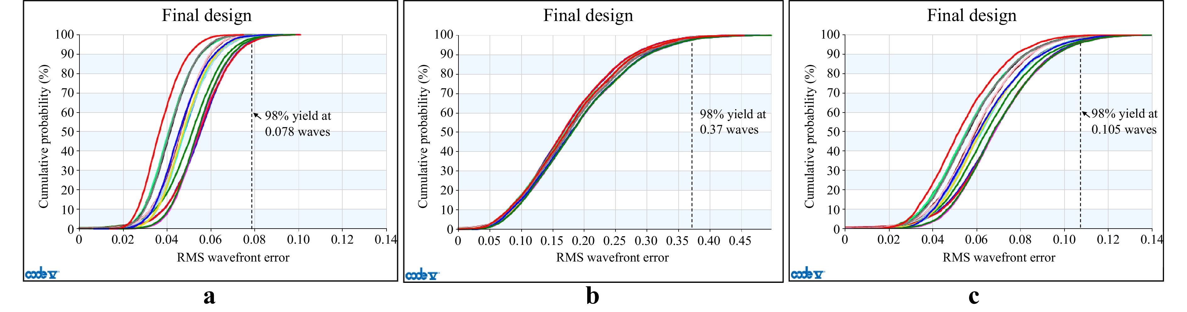
Fig. 6 Percent-yield plots for the final design after applying the tolerances in Table 3. In a the compensation of M5 is assumed to have infinite precision. Plot b shows the poor yield after adding the compensator precision of M5 (see Table 3) into the analysis. Plot c shows the vastly improved yield for the two-step assembly plan where M5 is first used as a compensator, then locked-down, after which M3 is decentered in X, Y, and Z to compensate for the lock-down error of M5.
To account for the lock-down error of M5 after compensation, an extra step was incorporated into the sensitivity analysis. M5 was perturbed from its ideal compensation position in all six DOFs. With this analysis, we found that M5 would have to be positioned and locked down to an X/Y/Z positioning tolerance of 0.5 µm and 1 arcsecond of tip/tilt to achieve near-diffraction-limited as-built performance. Such stringent positioning and lock-down tolerances are not realistically achievable. Consequently, an alternative assembly strategy was developed to relax the required precision for M5’s positioning and lock-down movement.
The compensation capability of M5 stems from its fast speed, which allows it to generate significant compensating aberrations with small movements–a fact that also makes it hard to lock into place without introducing residual errors. To mitigate these errors, we introduced a second compensator to correct specifically for M5’s lock-down errors. The X-Y-Z position of M3, a slow spherical mirror, was found to be effective in removing residual aberrations from the M5 lock-down error. Additionally, M3 is relatively insensitive, so its own lock-down errors remain minimal. The required tolerances for M3 after compensation were 25 μm in X/Y and 10 µm in Z, which are much more reasonable values to achieve. Using this multi-step compensation scheme, the design achieved a predicted 98% manufacturing yield at 0.105 waves, as shown in Fig. 6c. While not fully diffraction-limited, this outcome was satisfactory. The sequential compensation using M5 then M3 is appropriate for multiple reasons compared to parallel compensation. First, using two compensators in-parallel that have similar impact adds unnecessary complexity into the active alignment process without substantial gain. Second, there is not enough physical space to grab and move both M3 and M5 simultaneously in the housing. Third, compensating in-parallel would not reduce the lock-down error associated with M5. Thus, M3 was only used after M5 was locked-down post compensation.
-
With the multi-adjustment alignment method compensating for residual aberrations from manufacturing errors, the fixed mirrors (M1, M2, M4, and the fold mirror) have realistic placement tolerances. High-precision machining of the fixed mirrors is sufficient to meet the required mechanical tolerances. The mounting scheme for the mirrors in the microscope objective relies on a lapped baseplate to which each mirror is attached. Each fixed mirror features holes in its bottom flat surface that correspond to dowel pins on the baseplate, ensuring precise registration and constraint of X, Z, clocking, and tilt DOFs. The Y-position and tip of the static mirrors are constrained by locking screws threaded from beneath the baseplate, which pull each mirror flush against the baseplate, fully constraining all DOFs.
M3 is temporarily mounted in a similar manner but initially includes a shim between it and the baseplate to allow for removal for compensation of the M5 lock-down error. During the first alignment steps, M5 is held on a pre-aligned vacuum chuck, which is part of a multi-axis alignment tool used to position M5 for the final system alignment. Once the final position of M5 is found, it is bonded to the baseplate and released from the vacuum chuck. Because the bonding agent may cause slight movement during curing (i.e., lock-down error), M3 may then be unmounted and adjusted as the final alignment step before being permanently bonded to the baseplate. A 3D model of the baseplate and the six mirrors is shown in Fig. 7, alongside a CAD representation of the fully enclosed system, where a machined metal enclosure is attached to isolate the optics within the objective.
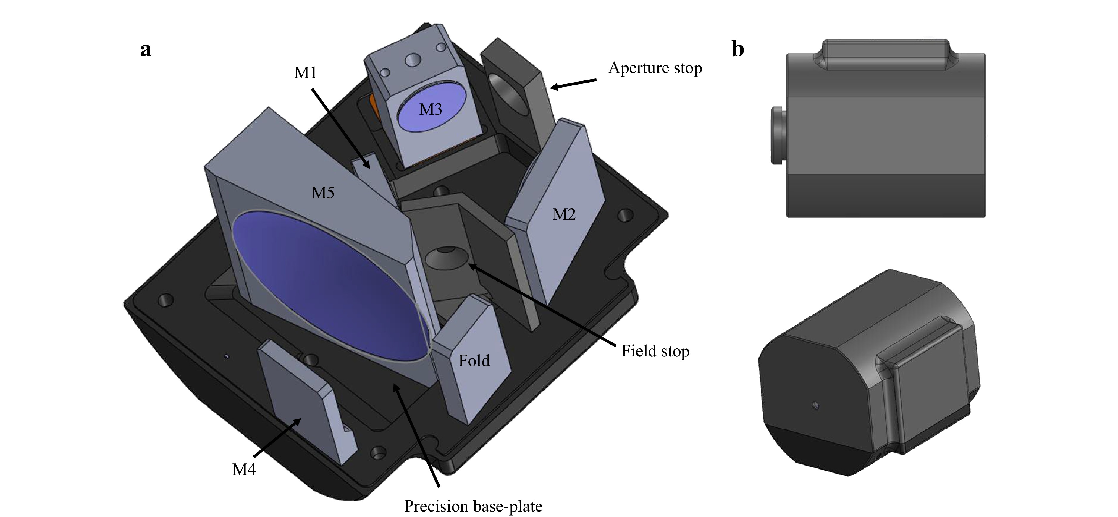
Fig. 7 Optomechanical design. a The internal mechanics of the housing assembly with the six mirrors shown mounted in place. b A CAD representation of the fully assembled system with the enclosure attached to the baseplate.
-
Given the active alignment steps necessary for this system, it is essential to have quantifiable feedback on the current alignment state. Fig. 8 shows a top view of the alignment station assembled for this purpose. Before installing the objective in the alignment station, a fiber-coupled laser source was collimated using a lens system with a wavefront sensor providing feedback control to ensure a quality beam, which then served as the reference axis. This collimated beam was then directed into the rough aligned objective as described above, where all mirrors except M5 were fixed in place using the pins and screws. M5 was held by a vacuum chuck with five DOFs for precise motion control.
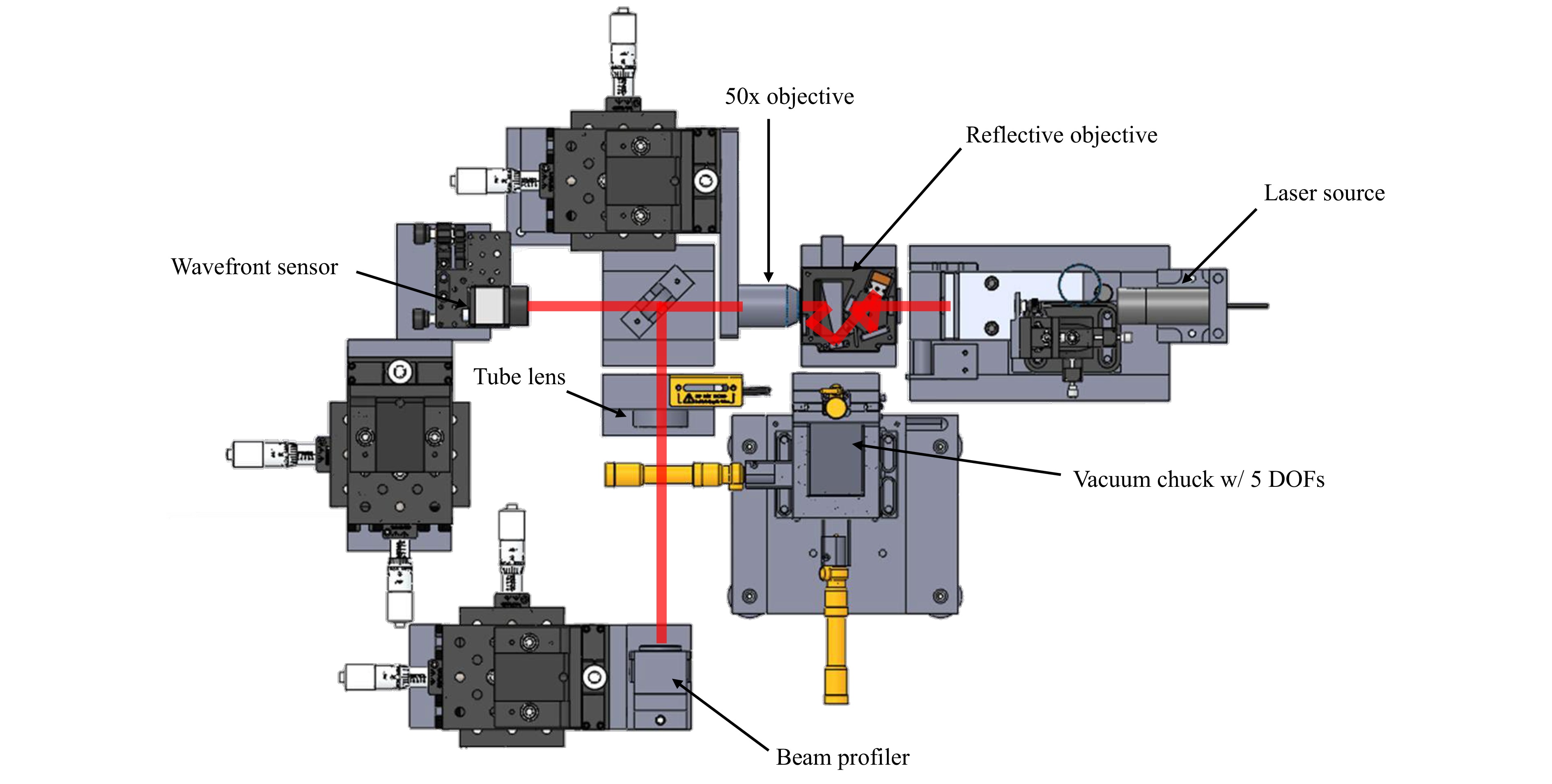
Fig. 8 Top view of the assembly station used for the active alignment of M5 and M3 in the objective.
Laser light was then focused by the objective in the vicinity of the nominal image plane, where it was picked up by a 50x commercial microscope objective that recollimated the beam. The beam output spot was steered by shifting the 50x objective until the beam was colinear to the input laser beam. The tilt of the 50x objective was controlled by use of an autocollimator that was aligned to the reflective objective’s base. The recollimated light passed through a tube lens and onto a beam profiler that was mechanically aligned to the beam center, providing quantitative feedback on the beam spot quality. Computer-controlled adjustments of M5’s five DOFs were performed while monitoring the imaging quality, aiming to find the M5 alignment that yield the best image. Due to the system’s high NA, a rough alignment was required before utilizing the beam profiler for fine tuning. Once the optimal position of M5 was determined, it was permanently cemented to the baseplate. The vacuum chuck was then transferred to M3, and the process was repeated. Because M3 is less sensitive than M5, this second compensation step proceeded more quickly.
-
The compact form factor of the mirrors and limited space for mechanical components pointed to the use of monolithic mounting structures integrated into each mirror. This design choice made diamond-machining the most reasonable fabrication method for all surfaces, even the spherical and flat optics. Freeform optics metrology is an industry-wide challenge and, as such, metrology of the final manufactured surfaces was not offered by the optics vendor. The mirrors were diamond machined from 6061 aluminum alloy using a 3-axis machine equipped with a slow-tool-servo. Subsequently, their optical surfaces were coated with a protected silver coating. Five copies of each mirror were fabricated. A full set is shown in Fig. 9 along with the nominal freeform departures for M2, M4 and M5 in Fig. 10.
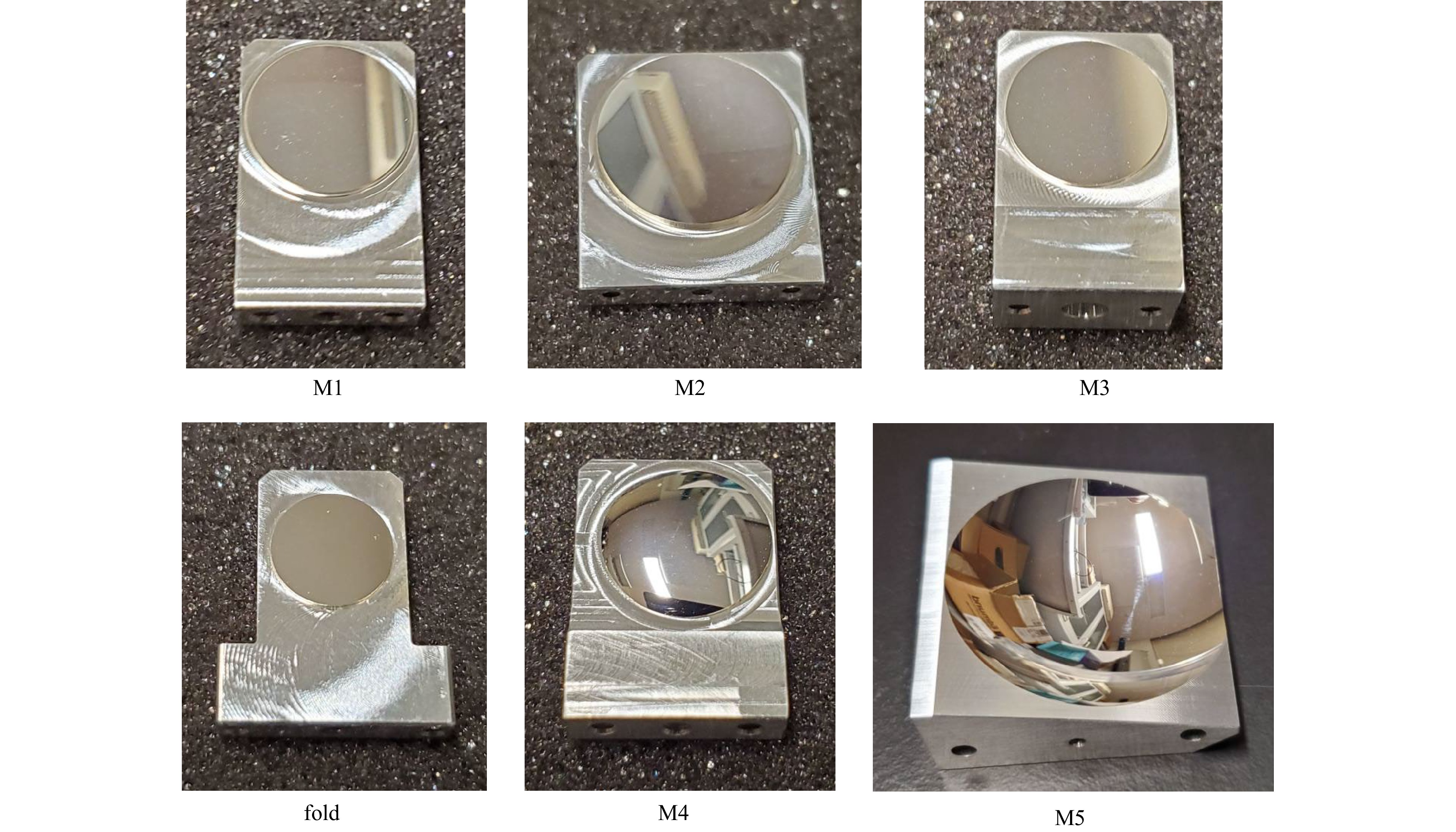
Fig. 9 One set of the diamond-machined and silver-coated mirrors.
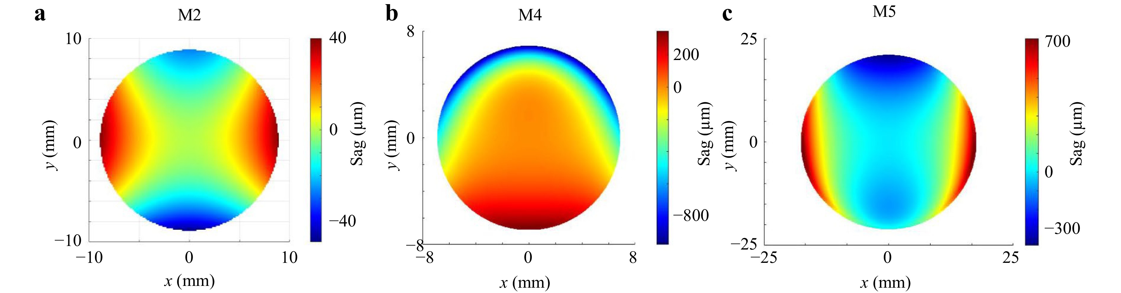
Fig. 10 Nominal freeform departure from base sphere for the three freeform mirrors a M2, b M4, and c M5.
-
To better understand the final optical surfaces and mechanical features, we measured one set of the six mirrors using our in-house non-contact optical coordinate measuring machine (CMM). This CMM is reported to have a peak-to-valley (PV) measurement accuracy of approximately 200 nm. The physical datums for each mirror were the bottom flat, the back flat, and one side flat. The parts were measured as they would be mounted in the housing, so the bottom flats were not accessible, thus the top flat was used for registration in the CMM instead. For validation and comparison, the spherical and flat mirrors were also measured using an interferometer.
The resulting surface error maps, referenced to the nominal prescription with rigid body motions removed, are shown in Fig. 11. While M1, M2, M3, and the fold mirror met their surface figure requirements, M4 and M5 presented significant challenges. Due to clearance issues between the CMM measurement probe and the M4 mechanical features, only a portion of its optical surface could be measured. Within the measured area of M4, and across the entire surface of M5, the figure error was far outside the specified tolerance.
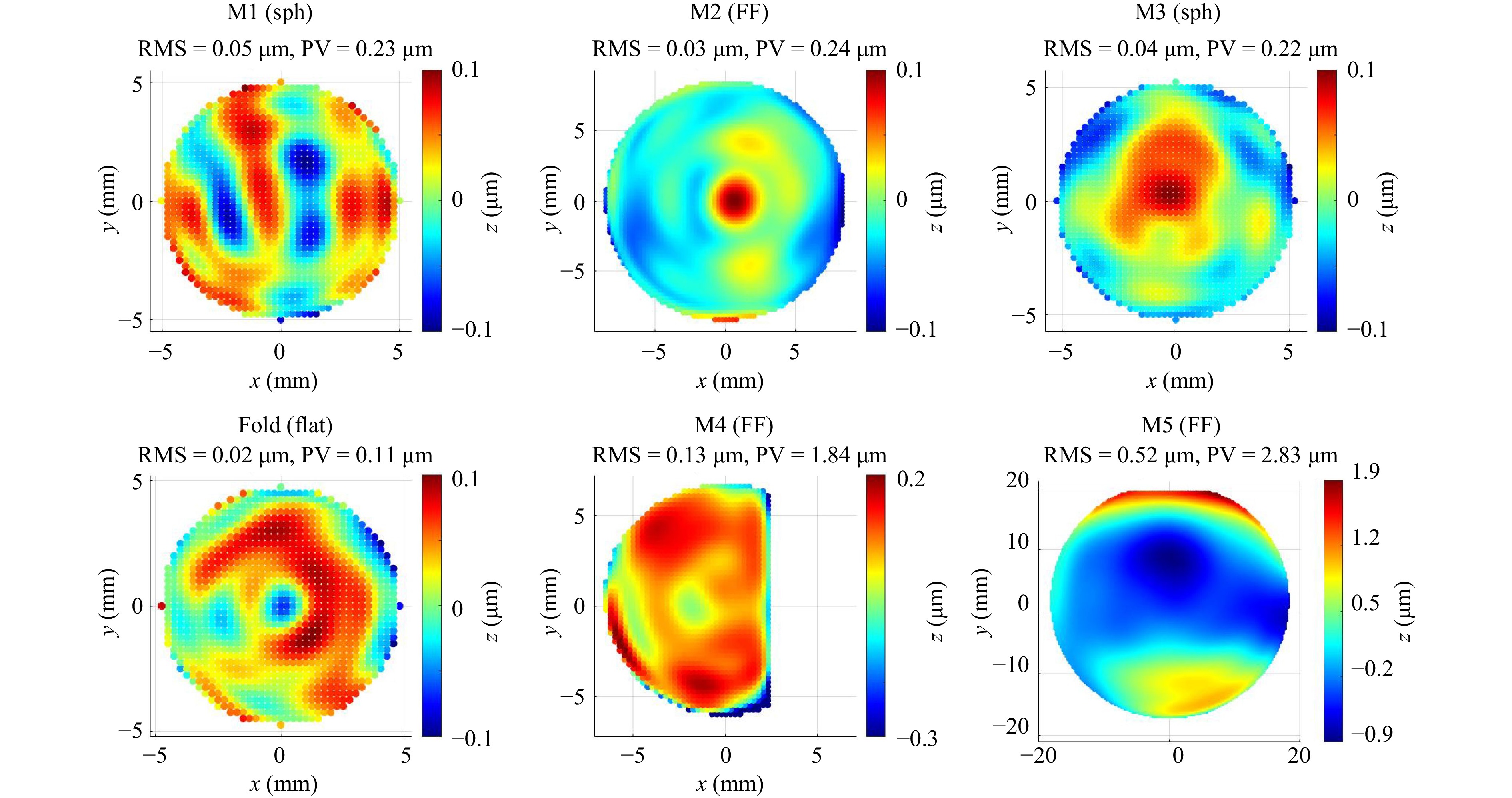
Fig. 11 Mirror figure error. Figure error for each mirror after subtracting the nominal surface prescriptions and rigid body motions for one set of the six mirrors as measured with an optical CMM (Optipro UltraSurf 5x 400).
This outcome underscores the difficulty in fabricating optics with large surface slopes and steep base curvatures, as M4 and M5 exhibited the steepest slopes among the mirrors. Due to the high NA of the microscope objective that results in steep marginal ray angles in image space, the highly curved M4 and M5 mirrors that pose fabrication and metrology challenges are largely unavoidable in design. To further reduce form errors on these aggressive surfaces, feedback from in-shop surface metrology could be used to facilitate re-machining of the mirrors. Reliable methods such as computer-generated holograms (CGHs) can be employed as nulling optics to reduce the interferometry fringe density and, ultimately, provide the metrology data necessary for correction of the optics. However, for prototyping projects requiring only a small number of mirror copies, CGHs are often prohibitively expensive, costing between $25k-$40k for each optic to be measured. This is due not only to the cost of fabricating the CGH itself, but also the need for a custom alignment and optomechanical setup tailored to each specific CGH-interferometer configuration. As a result, this approach remains largely inaccessible for most prototyping efforts. Looking ahead, reconfigurable CGHs may offer a more practical solution for future metrology application and are currently under development24–26.
The interferometric measurement results for the rotationally symmetric parts (M1, M3, and fold) are shown in Fig. 12, confirming that their surface figures are quite good. Importantly, the observed errors in the interferometry data are below the accuracy threshold of the CMM, indicating that the corresponding CMM error maps for these mirrors are dominated by CMM measurement noise. Since multiple copies of the mirrors were fabricated, the measured set reported here is different than the set that was used to assemble the first system. However, mirrors exhibiting surface errors like those measured for M4 and M5 would undoubtedly degrade overall system performance.
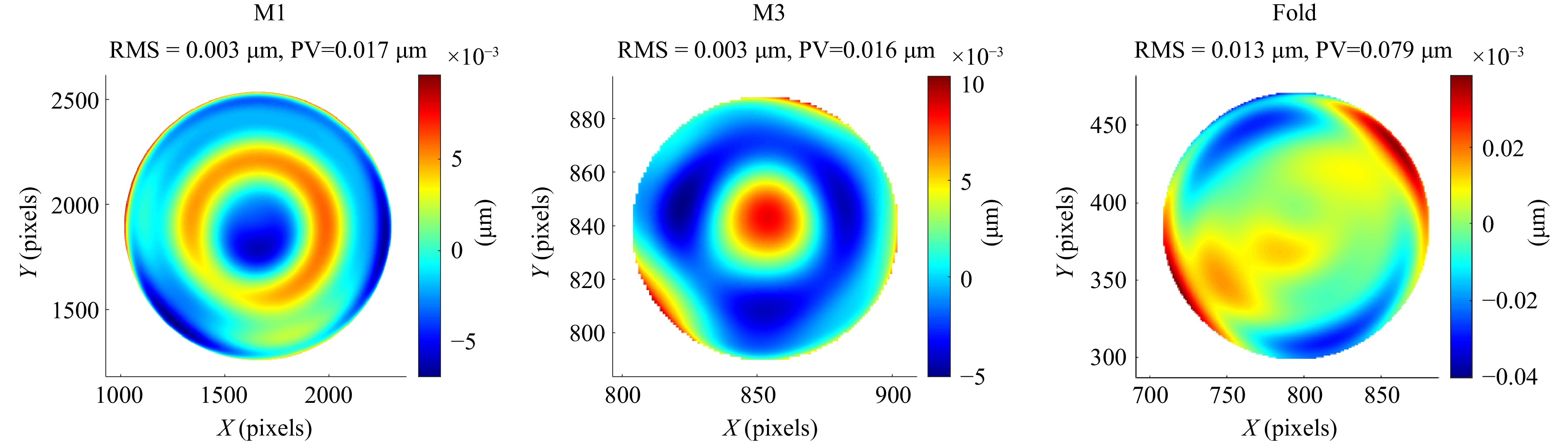
Fig. 12 Mirror interferometry. Interferometrically measured figure error for the rotationally symmetric mirrors with tip, tilt, and power removed.
-
The first system was assembled following the procedure outlined in Section 3.2, resulting in the objective shown in Fig. 13a, b. During assembly, the extreme sensitivity of M5 posed a significant challenge. The original plan to use manual stage actuation proved impractical, as even the slightest touch of the actuators caused excessive mirror movement. Computer-controlled actuators facilitated the compensation step and provided the requisite sensitivity for M5 movement. Computer simulations of misalignments proved instrumental in finding good starting points for the DOF scan. These simulations revealed how specific mirror adjustments produced characteristic changes in the beam shape, helping to determine which DOF to adjust to iteratively walk M5 toward its optimal position.
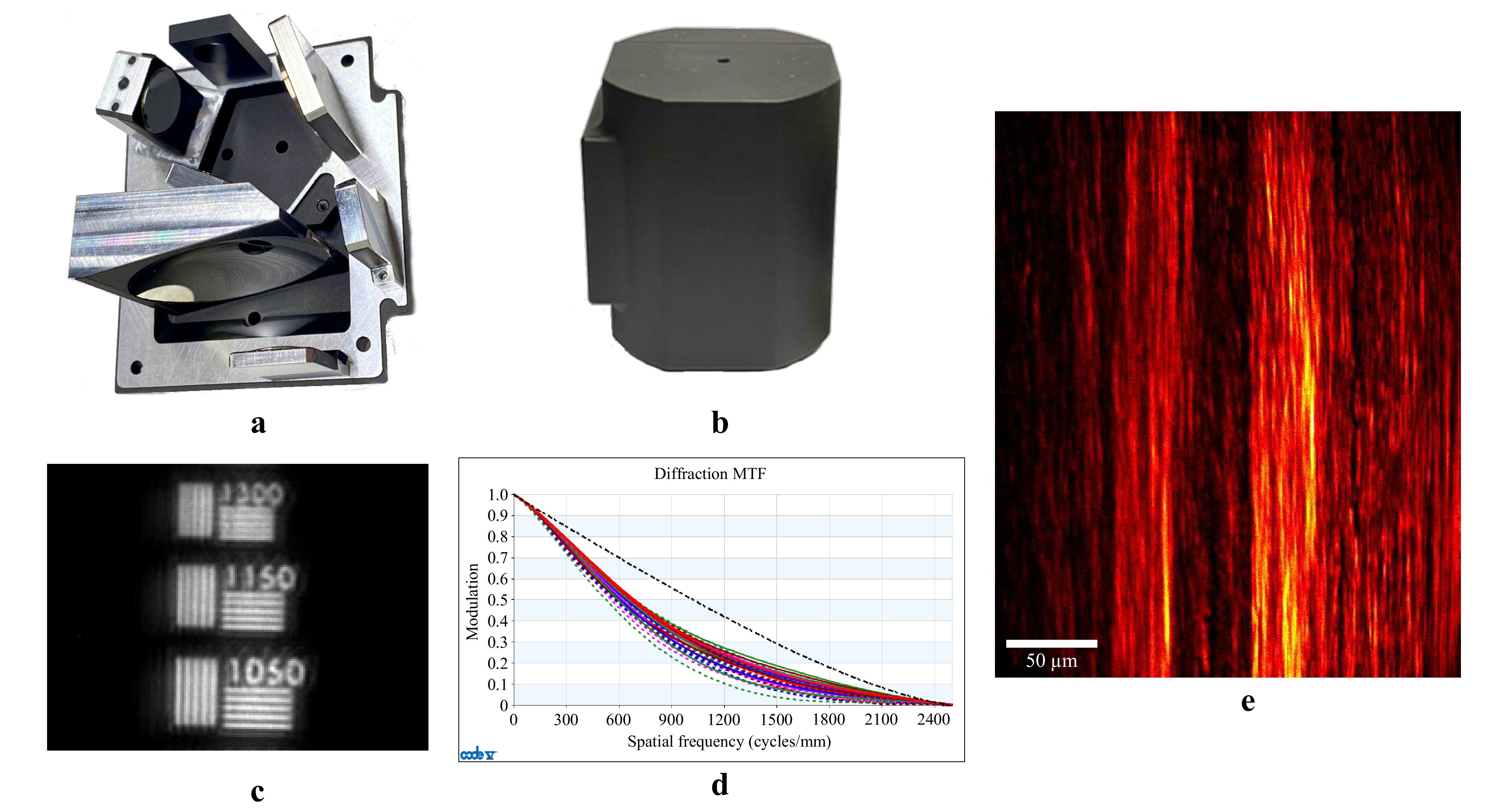
Fig. 13 Assembled Objective. a The assembled objective without the enclosure. b The assembled objective with the enclosure attached. Its cylindrical dimensions measure roughly 70 mm in height and 50 mm in diameter. c An initial image of a high-resolution target (Edmund Optics #37-539) captured using the objective, where line pairs of the indicated frequencies are resolved using 528 nm light. d MTF plot for an example system with simulated fabrication errors resulting in performance of ~0.11 waves RMS. e An image of collagen acquired using sum-frequency generation microscopy that uses excitation wavelengths of 1,030 nm and 3,395 nm.
An image of a high-resolution target (Edmund Optics #37-539) was captured using the objective and 528 nm illumination, as shown in Fig. 13c. The Rayleigh criterion stipulates that the smallest resolvable dimension of a diffraction-limited 0.65 NA objective at 528 nm is 496 nm. This resolution corresponds to a line spacing of about 2018 lp/mm. In Fig. 13c, the 1,300 lp/mm set can be clearly resolved, but apparent aberrations limit higher line spacings from being properly resolved. Fig. 13d shows an MTF plot for the final design with a set of random manufacturing tolerances applied that results in an RMS WFE of 0.11 waves, which was the predicted as-built performance. Based on that MTF plot, the assembled design is close to expectations. Noticeable image artifacts manifesting as ghosting or image replication limit the achievable resolution. Additionally, as shown in Fig. 13e, initial biological imaging was performed with the assembly objective that highlights its wide-field and high-contrast advantages. A detailed characterization of the microscope objective’s performance for imaging is presented in a separate publication with an emphasis on the objective’s application in the area of NLO microscopy27.
The origin of the observed artifacts is under further investigation, but they likely result from a combination of the surface figure error of M4 and M5, especially astigmatic error in the surface shape, residual system aberration, and mid-spatial frequency (MSF) errors of the diamond-machined surfaces. Residual astigmatism could cause the observed replication given its property of creating dual focal planes. Because both mirror figure error and residual misalignments can introduce astigmatism, it is difficult to conclusively distinguish between these contributions without confirmation of the metrology of the freeform surface shapes with an independent method. Specifically for MSF errors, repeated structures like those commonly seen in diamond-turning toolpaths can act like a diffraction grating where light is diverted into the nonzero diffraction orders causing image blur or ghosting28. To reduce the impact of the MSF errors, it is helpful to avoid regular tool paths like rasters or spirals29. If this is not feasible, tolerancing of MSFs to limit their impact on image quality, specifically image blur and ghosting, to below a predefined threshold remains an active area of research that we anticipate will be fully integrated into future design workflows30. Finally, as needed, the surfaces could undergo post-polishing using a technique such as ion beam polishing31.
-
In the process of designing and manufacturing an all-reflective freeform microscope objective, we encountered numerous challenges stemming from the steeply curved surfaces that are required for unobscured, high-NA imaging in a compact format. Using desensitization optimization and a concurrent engineering approach, we addressed these challenges and delivered a first-of-its kind optical system and first light through the system. Further advancing the precision in the optical surface fabrication (surface form and mid-spatial frequency errors), which critically relies on metrology, especially for those surfaces with high slopes, will be critical to reducing risk and enabling the broader deployment of these systems. For mass production of these systems, CGHs can be leveraged in metrology to ensure all surface forms, even the most challenging ones, fall within specification.
-
This research is synergistic with the National Science Foundation I/UCRC Center for Freeform Optics (CeFO) (EEC-2310640, EEC-2310681); National Institutes of Health (R43GM149018, R21-EB034084); National Science Foundation (2221721).
Design-for-manufacture, fabrication, and assembly of an all-reflective freeform microscope objective
- Light: Advanced Manufacturing , Article number: 113 (2026)
- Received: 16 February 2026
- Revised: 30 June 2026
- Accepted: 30 June 2026 Published online: 13 August 2026
doi: https://doi.org/10.37188/lam.2026.113
Abstract: All-reflective microscope objectives offer distinct advantages for microscopy techniques that operate across widely separated spectral bands. However, designing a high numerical-aperture (NA), unobscured, all-reflective objective that is manufacturable remains a substantial challenge, requiring early integration of fabrication considerations into the optical design process. In this work, we present design-for-manufacture strategies for a 0.65-NA unobscured all-reflective microscope objective enabled by freeform optics. These strategies include minimizing freeform departures, desensitization optimization, and a stray-light analysis. Concepts for mounting and assembly are also introduced and implemented, culminating in the successful fabrication and imaging demonstration of the first system of its kind.
Research Summary
Freeform optics: Enabling the next generation of achromatic microscopy
Reflective microscope objectives have the potential to transform advanced microscopy by eliminating chromatic aberrations and pulse dispersion across an exceptionally wide range of wavelengths. However, their adoption has been hindered by the difficulty in designing, manufacturing and assembling compact, high-performance freeform optical systems. Aaron Bauer from the University of Rochester and his colleagues now demonstrate a comprehensive design-for-manufacture methodology for an unobscured all-reflective freeform microscope objective. By integrating robust optical design, manufacturability optimization, tolerance analysis, precision fabrication, and active alignment into a unified workflow, the team successfully fabricated and assembled the first high-numerical-aperture system of its kind. The work provides a practical pathway for translating complex freeform optical designs into next-generation microscope objectives for ultra-broadband biological imaging and other advanced optical applications.
Rights and permissions
Open Access This article is licensed under a Creative Commons Attribution 4.0 International License, which permits use, sharing, adaptation, distribution and reproduction in any medium or format, as long as you give appropriate credit to the original author(s) and the source, provide a link to the Creative Commons license, and indicate if changes were made. The images or other third party material in this article are included in the article′s Creative Commons license, unless indicated otherwise in a credit line to the material. If material is not included in the article′s Creative Commons license and your intended use is not permitted by statutory regulation or exceeds the permitted use, you will need to obtain permission directly from the copyright holder. To view a copy of this license, visit http://creativecommons.org/licenses/by/4.0/.

 DownLoad: