






HTML
-
Light-matter interactions involving optical chirality have attracted significant interest over the past decade, driven by the rapid development of chiral metasurfaces, polarisation-selective photonic devices, and compact platforms for controlling the handedness of light. A fundamental limitation of conventional homogeneous isotropic mirrors is that they invert the handedness of the circularly polarised light upon reflection. Overcoming this limitation and achieving handedness-preserving reflections are crucial in various fields of applied photonics.
One of the most intriguing applications of optical chirality is the development of highly sensitive sensors for chiral molecules. This challenge is essential in pharmaceutical and biological systems, where the specific chirality of a compound determines its bioactivity and toxicity1,2. A promising route toward enhanced enantioselective detection involves nanophotonic structures that resonantly amplify the weak interactions between chiral light and chiral matter3−6. Resonators supporting high-quality chiral electromagnetic modes can interact differently with left- and right-handed molecules, enabling highly sensitive measurements from small analyte volumes7,8. Various platforms, such as chiral metamaterials7,9−11, plasmonic helices12−15, nanoparticles16,17, and complex chiral metasurfaces18−22, have been explored for this purpose. Among these, the Fabry-Pérot architecture23−26 remains particularly attractive because of its conceptual simplicity, strong field confinement, and compatibility with established fabrication processes.
If conventional homogeneous isotropic mirrors invert the handedness of light upon reflection, a key requirement for implementing a Fabry-Pérot resonator that supports chiral modes is the creation of a handedness-preserving mirror24,26. Several approaches have been proposed for implementing handedness-preserving reflections, including three-dimensional chiral metamaterials27−29, anisotropic multilayer coatings30, and low-symmetry periodic metasurfaces24,26,31−34. Ref. 24,32 reported in-plane chiral metasurfaces that demonstrated near-perfect reflection of one circular polarisation with handedness preservation and transparency for the opposite polarisation. The required functionality is achieved when a structure has a pair of orthogonal eigenstates with opposite parities24.
The resonant nature of low-symmetry handedness-preserving mirrors significantly restricts their operating bandwidth. This, along with the fabrication complexity, substantially limits the practical applicability of resonant metasurfaces. Broadband metasurfaces are an alternative to resonant structures35−39. The broadband effect in such devices is typically achieved via two distinct approaches: the integration of a family of low-quality resonances within a single structure to collectively span a broad spectral range or the utilisation of non-resonant metasurfaces.
In this study, we used the second approach and demonstrated a non-resonant broadband handedness-preserving mirror based on a one-dimensional dielectric grating placed on top of a distributed Bragg reflector. The grating provides in-plane anisotropy, whereas the Bragg mirror ensures high reflectivity and stabilises the spectral phase response. We demonstrate that these elements preserve handedness upon reflection across a wide wavelength range. The operating range of the proposed metasurface is within the stop-band of the Bragg mirror. This design relies solely on standard dielectric materials and fully planar fabrication, making it compatible with scalable nanolithography.
-
To describe the reflection of a normally incident circularly polarised wave from the mirror, we use the Jones calculus formalism, where the electric field of the wave is expressed in terms of a complex vector of amplitudes written in the linear polarisation basis (denoted as ‘$ {\text{π}}$’) or circular polarisation basis (denoted as ‘$ \sigma $’):
$$ {{\boldsymbol{A}}}_{{\text{π}}} = \left[\begin{array}{*{20}{c}} {a_x}\\{a_y } \end{array}\right],\; \; \; \; \; \; \; {\boldsymbol{A}}_{\sigma} = \left[\begin{array}{*{20}{c}} { a_{\sigma^+}}\\{a_{\sigma^-} } \end{array}\right] $$ (1) with a transformation matrix $ \boldsymbol{T} $:
$$ \boldsymbol{T}\equiv\boldsymbol{T}_{\sigma \leftarrow {\text{π}}} = \dfrac{1}{\sqrt{2}} \left[\begin{array}{*{20}{c}} {1} & {i} \\ {1} & {-i} \end{array}\right] $$ (2) such that $ {{\boldsymbol{A}}}_{\sigma} = \boldsymbol{T}{{\boldsymbol{A}}}_{{\text{π}}} $. Because the vector of amplitudes can describe waves propagating in either the positive or negative $ {\textit{z}} $-direction, we introduce the notation $ {{\boldsymbol{A}}}^{\rm{inc}} $ for an incident wave and $ {{\boldsymbol{A}}}^{\rm{refl}} $ for a reflected wave. Note that for incidence along the $ {\textit{z}} $-direction, the vectors $ {{\boldsymbol{A}}}^{\rm{inc}}_{\sigma} = [1, 0]^{\rm T} $ and $ {{\boldsymbol{A}}}^{\rm{refl}}_{\sigma} = [0, 1]^{\rm T} $ describe a right-handed (RH) wave, whereas the vectors $ {{\boldsymbol{A}}}^{\rm{refl}}_{\sigma} = [1, 0]^{\rm T} $ and $ {{\boldsymbol{A}}}^{\rm{inc}}_{\sigma} = [0, 1]^{\rm T} $ correspond to a left-handed (LH) wave. Conventional homogeneous isotropic mirrors reflect both linear orthogonal polarisations with the same complex amplitude reflection coefficient $ r $. Thus, the reflection matrix of such a mirror on a linear basis is
$$ \boldsymbol{R}_{{\text{π}}} = \left[\begin{array}{*{20}{c}} {r} & {0}\\ {0} &{r}\end{array}\right] $$ (3) whereas on a circular basis, according to $ {\boldsymbol{A}}_{\sigma}^{{\rm{refl}}} = \boldsymbol{T}{\boldsymbol{A}}_{{\text{π}}}^{{\rm{refl}}} = \boldsymbol{T}\boldsymbol{R}_{{\text{π}}}{\boldsymbol{A}}_{{\text{π}}}^{{\rm{inc}}} = \boldsymbol{T}\boldsymbol{R}_{{\text{π}}}\boldsymbol{T}^{-1}{\boldsymbol{A}}_{\sigma}^{\rm{inc}} $, it takes the form
$$ \boldsymbol{R}_{\rm{\sigma}} = \boldsymbol{T}\boldsymbol{R}_{{\text{π}}}\boldsymbol{T}^{-1} = \left[\begin{array}{*{20}{c}} {r} & {0}\\ {0} &{r} \end{array}\right] $$ (4) The reflection matrix $ \boldsymbol{R}_{\rm{\sigma}} $ of the isotropic mirrors preserves circular polarisation but inverts handedness:
$$ \boldsymbol{R}_{\sigma}{{\boldsymbol{A}}}^{\rm{inc}}_{\sigma} = \left[\begin{array}{*{20}{c}} { r} &{ 0}\\{ 0 } & {r} \end{array}\right] \left[\begin{array}{*{20}{c}} {1}\\ {0 } \end{array}\right]^{\rm{inc}}_{\text{RH}} = \left[\begin{array}{*{20}{c}} {r}\\{0 } \end{array}\right]^{\rm{refl}}_{\text{LH}} \equiv {{\boldsymbol{A}}}^{\rm{refl}}_{\sigma} $$ (5) In contrast to isotropic mirrors, handedness-preserving mirrors invert circular polarisation while preserving its handedness, as reflected in their name. Thus, the corresponding reflection matrix on a circular basis is anti-diagonal:
$$ \boldsymbol{R}_{\sigma}{{\boldsymbol{A}}}^{\rm{inc}}_{\sigma} = \left[\begin{array}{*{20}{c}} { 0} & {r'}\\ {r }&{0 } \end{array}\right] \left[\begin{array}{*{20}{c}} 1\\0 \end{array}\right]^{\rm{inc}}_{\text{RH}} = \left[\begin{array}{*{20}{c}} 0\\r \end{array}\right]^{\rm{refl}}_{\text{RH}} \equiv{{\boldsymbol{A}}}^{\rm{refl}}_{\sigma} $$ (6) Nonzero diagonal elements of the matrix $ \boldsymbol{R}_{\sigma} $ lead to the mixing of orthogonal polarisations, resulting in elliptically polarised reflected light instead of the desired circular state. By considering only symmetric handedness-preserving mirrors that reflect LH and RH incident waves with equal amplitude reflection coefficients ($ r = r' $), we obtain the reflection matrices in the linear and circular polarisation bases in the following form:
$$ \boldsymbol{R}_{\rm{\sigma}} = \left[\begin{array}{*{20}{c}} {0} &{r}\\ {r }&{0} \end{array}\right],\; \; \; \boldsymbol{R}_{{\text{π}}} = \boldsymbol{T}^{-1}\boldsymbol{R}_{\rm{\sigma}}\boldsymbol{T} = \left[\begin{array}{*{20}{c}} { r} &{ 0}\\ {0} &{-r} \end{array}\right] $$ (7) The expression for the reflection matrix in a linear basis $ \boldsymbol{R}_{{\text{π}}} $ indicates that preserving the handedness of light upon reflection requires a reflective surface to be designed with two key properties: First, the amplitude reflection coefficients for the $ x $ and $ y $-polarisations must sum to zero ($ r_{xx}+r_{yy} = 0 $), equivalently their magnitudes must be equal, $ |r_{xx}| = |r_{yy}| $, whereas phase difference corresponds to an odd multiple of $ {\text{π}} $ ($ \Delta\phi = \arg(r_{xx}) - \arg(r_{yy}) = {\text{π}}(2n + 1) $, where $ n \in \boldsymbol{Z} $). Second, the cross-polarisation coefficients in the linear basis must vanish ($ r_{xy} = r_{yx} = 0 $). For the surface to act as a high-quality mirror, an additional condition of perfect reflectivity, $ |r_{xx}|^2 = |r_{yy}|^2 = 1 $, must also be satisfied. In contrast to earlier approaches24,32, a system that satisfies these criteria must exhibit in-plane anisotropy while maintaining a vertical plane of mirror symmetry. The simplest structure that fulfils these requirements is a homogeneous slab that is anisotropic within the horizontal plane. Although naturally anisotropic materials can, in principle, satisfy these conditions at a specific thickness, their typically weak anisotropy $ \Delta n $ results in an impractically narrow operating bandwidth. Periodic metasurfaces, however, can provide a substantially stronger in-plane anisotropy. In the following section, we present a metasurface design that simultaneously satisfies all of the above criteria, thereby enabling a broadband, high-quality mirror that preserves the handedness of the reflected light.
-
The proposed structure consists of a one-dimensional Si/air grating placed on top of a Si/SiO2 Bragg mirror, as shown in Fig. 1a. Our objective is to determine a set of geometric parameters of the model structure to minimise the target function $ {{f}}_1 = |r_{xx}+r_{yy}| $ while maximising the target function $ {{f}}_2 = |r_{xx}|^2+|r_{yy}|^2 $ over the wavelength range 1,400–1,800 nm. An ideal handedness-preserving mirror corresponds to $ {{f}}_1 = 0 $ and $ {{f}}_2 = 2 $. Using a genetic algorithm, we optimise the layer thicknesses $ h_{{\rm{gr}}} $, $ h^{\rm{sub}}_\mathrm{SiO_2} $, $ h^{\rm{BM}}_{\rm{Si}} $, $ h^{\rm{BM}}_\mathrm{SiO_2} $, grating period $ p $, and Si wall width $ a $. Thicknesses of the Si and SiO2 layers in the Bragg mirror are taken such that the central wavelength is $ \lambda=1,550 $ nm (see details in the Supplemental Material). Introducing a thin SiO2 sublayer between the grating and top Si layer of the Bragg mirror broadens the operating bandwidth.
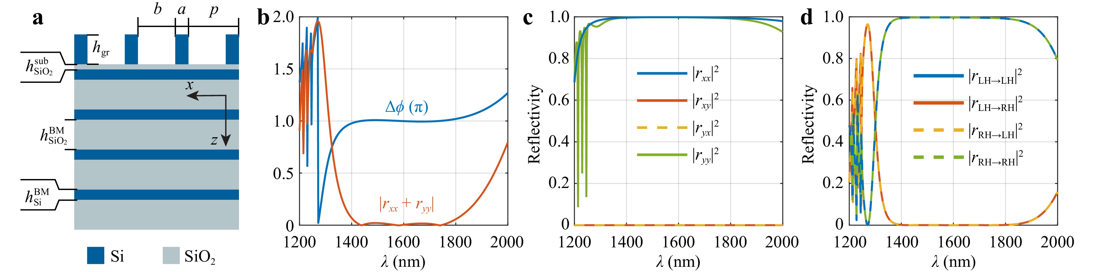
Fig. 1 Modelling. a The sketch of a wide-band handedness-preserving mirror consisting of the one-dimensional Si grating on a Si/SiO2 multilayered structure. b Spectral dependence of $ \Delta \phi = \arg(r_{xx})-\arg(r_{yy}) $ and $ |r_{xx}+r_{yy}| $. c Spectral dependencies of co- and cross-polarisation reflection coefficients in the basis of linear polarisations. d Spectral dependencies of co- and cross-handed reflection coefficients. Optimized geometric parameters: thicknesses of the layers was $ h_{{\rm{gr}}} = 297 $ nm (grating), $ h_{\text{SiO}_2}^{\text{sub}} = 50 $ nm (SiO2 sublayer), $ h_{\text{Si}}^{\text{BM}} = 102 $ nm (Si layer of the Bragg mirror), $ h_{\text{SiO}_2}^{\text{BM}} = 297 $ nm (SiO2 layer of the Bragg mirror); the period $ p = 503 $ nm; the stripes' width $ a = 131 $ nm the grooves' width $ b = 372 $ nm.
The reflection spectra of a structure with optimised geometric parameters are shown in Fig. 1. In the range of 1,400−1,800 nm, the designed structure simultaneously satisfies the requirements $ r_{xx}+r_{yy} = 0 $ and $ |r_{xx}| = |r_{yy}|=1 $ where the cross-polarisation amplitude coefficients $ r_{xy} $ and $ r_{yx} $ are zero. Consequently, the structure functions as a handedness-preserving mirror within this spectral range, reflecting LH light into LH light and RH light into RH light, as illustrated in Fig. 1d.
The operating bandwidth of the mirror is governed primarily by the spectral range over which the condition $ r_{xx}+r_{yy} = 0 $ is satisfied, rather than by the reflectance band of the underlying Bragg mirror; the latter is substantially broader. In Fig. 1d, in addition to a wide handedness-preservation band, several sharp dips are observed near 1,200 nm. These parasitic resonant features originate from the excitation of waveguide modes within the silicon layers of the Bragg mirror, which is mediated by diffraction from the grating. Under oblique incidence, these resonances split because of the lifting of polarisation degeneracy (see details in the Supplemental Material).
As shown in Fig. 1, the effect of handedness preservation is non-resonant because it is wideband and falls entirely within the stopband of the Bragg mirror. This indicates that the underlying mechanism does not rely on sharp, narrowband resonances, but rather on the engineered anisotropic properties of the effective medium.
Because the handedness-preserving functionality is non-resonant, the designed mirror should be stable against geometric imperfections. In the following, we analyse the tolerance of the structure to geometric fabrication imperfections across all geometrical parameters. We first assess the grating period, as shown in Fig. 2a. Increasing the period slightly narrows the operating bandwidth and shifts it toward longer wavelengths. A variation of up to 50 nm preserves the reflectance above 90% across the entire band from 1,400 to 1,800 nm. The most sensitive parameter is the filling factor (Fig. 2b) because it directly determines the in-plane anisotropy of the layer and, consequently, the phase retardance between the $ r_{xx} $ and $ r_{yy} $ components. Nevertheless, the reflection is maintained above 90% for variations in the filling factor within $ \pm15\% $ that correspond to a change of $ \pm75 $ nm in the widths of the grooves and stripes. The dependence on the grating thickness $ h_{\text{gr}} $ (Fig. 2c) is qualitatively similar to the dependence on the grating period (Fig. 2a). The response remains highly robust, with the reflectance remaining above 90% throughout the band. The operating range shifts slightly toward longer wavelengths owing to a minor increase in the phase difference between the $ r_{xx} $ and $ r_{yy} $ components, $ \Delta\phi $, as the grating thickness increases. As shown in Fig. 2d, the broadest spectral range with a reflectance exceeding 99% is achieved at the optimal SiO2 sublayer thickness. Nevertheless, for all sublayer thicknesses presented in Fig. 2d, the reflectance remains above 90% across the entire spectral band. Notably, even in the absence of the SiO2 sublayer, the structure continues to function as a handedness-preserving mirror, although with approximately half the operating bandwidth. Fig. 2e shows the reflection coefficient for simultaneous variations in the thicknesses of the Si and SiO2 layers of the Bragg mirror. A thickness deviation of $ \pm10 $ nm does not reduce the width of the operating band, and even a deviation of $ \pm20 $ nm maintains a reflection above 90% across the entire band.
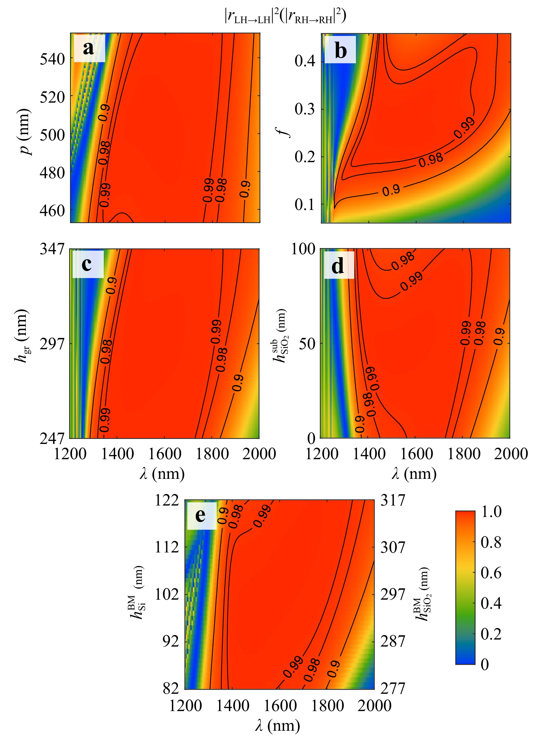
Fig. 2 Modelling. Reflection coefficient for LH→LH (RH→RH) polarisation as a function of the light wavelength and structural parameters: a grating period $ p $, b filling factor $ f = a/p $, c grating thickness $ h_{{\rm{gr}}} $, d SiO2 sublayer thickness $ h_{\text{SiO}_2}^{\text{sub}} $, and e Bragg mirror layers thickness $ h_{\text{Si}}^{\text{BM}} $, $ h_{\text{SiO}_2}^{\text{BM}} $ that was changed simultaneously. Initial parameters used for modelling: $ h_{{\rm{gr}}} = 297 $ nm, $ h_{\text{SiO}_2}^{\text{sub}} = 50 $ nm, $ h_{\text{Si}}^{\text{BM}} = 102 $ nm, $ h_{\text{SiO}_2}^{\text{BM}} = 297 $ nm, $ p = 503 $ nm, $ a = 131 $ nm, $ b = 372 $ nm.
Another important characteristic of the designed mirror is its stability with respect to the angle of incidence. Fig. 3 shows the angular dependence of the co-polarised reflection spectrum on the circular basis. When the plane of incidence is perpendicular to the stripes (left panel of Fig. 3), the waveguide resonances redshift with an increasing incident angle, restricting the operating bandwidth of the mirror. However, outside these resonances, the reflectance remains high over a wide spectral range, reaching up to 99% for incidence angles below $ 20^{\circ} $ and above 90% for angles up to $ 50^{\circ} $. In contrast, when the plane of incidence is parallel to the stripes (right panel of Fig. 3), no resonant features appear in the spectral–angular region of interest, which ensures high stability of the mirror performance with respect to the incident angle. Consequently, the reflectance remains high over the entire 1,400−1,800 nm range, exceeding 99% for angles below 20° and remaining above 90% for angles up to 50°. See additional details in the Supplemental Material in Waveguide Modes section.
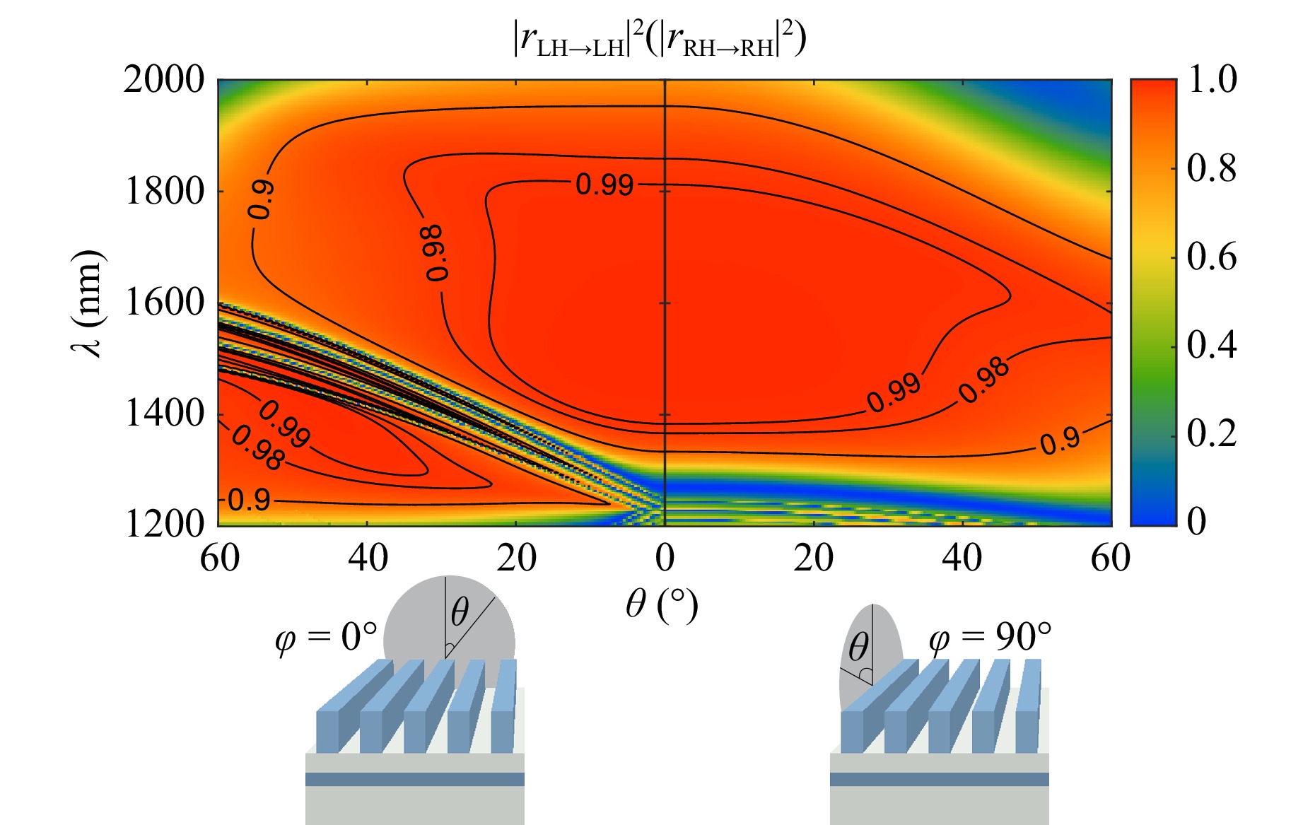
Fig. 3 Modelling. Reflection coefficient for LH→LH (RH→RH) polarisation as a function of the light wavelength and incidence angle $ \theta $: incidence perpendicular to the grating stripes and parallel to the grating stripes. Parameters used for modelling: $ h_{{\rm{gr}}} = 297 $ nm, $ h_{\text{SiO}_2}^{\text{sub}} = 50 $ nm, $ h_{\text{Si}}^{\text{BM}} = 102 $ nm, $ h_{\text{SiO}_2}^{\text{BM}} = 297 $ nm, $ p = 503 $ nm, $ a = 131 $ nm, $ b = 372 $ nm.
Please note that the theoretical results in this section are based on the assumption that the structure contains high-quality crystalline silicon and that the scattering losses are negligible; therefore, they represent the theoretical maximum for the handedness-preservation effect achievable on the Si/SiO2 platform and one-dimensional grating.
-
To verify our theoretical findings, we fabricated two mirror samples with different geometric parameters. In both samples, the Si parts were amorphous, and the Bragg mirror consisted of three Si/SiO2 pairs. The geometric parameters of Sample 1 were close to the theoretically optimal values obtained for amorphous Si. The geometric parameters of Sample 2 were altered to experimentally observe the impact of the non-optimal geometry. The details of the sample fabrication procedure are provided in the Materials and Methods section. Fig. 4a, b shows a scanning electron microscopy (SEM) image of the fabricated grating and Bragg mirror corresponding to Sample 2.
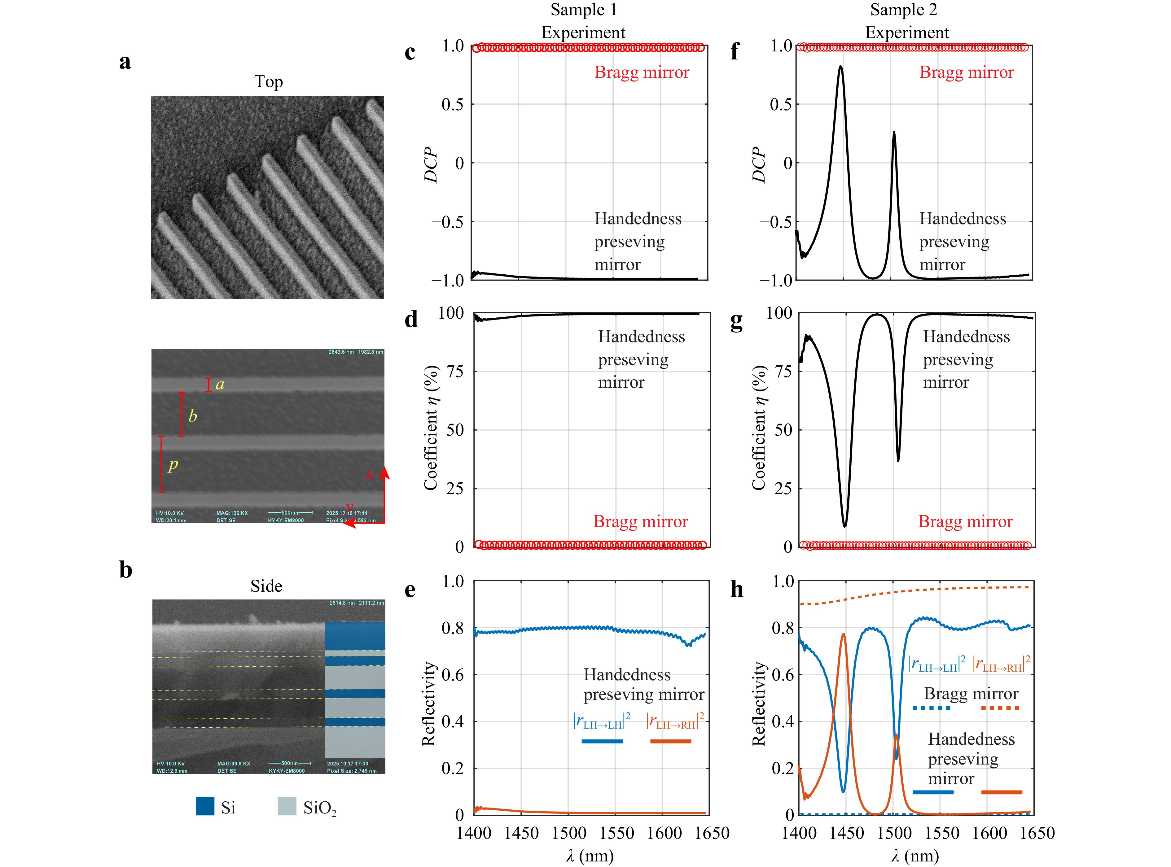
Fig. 4 Experiment. a SEM image of the grating fabricated on top of the Si/SiO2 Bragg mirror. b SEM image of the side cross section of the unprocessed Bragg mirror (for Sample 2). Spectral dependence of the c, f DCP and d, g handedness-preservation coefficient $ \eta $ for the bare Bragg mirror (red markers) and the fabricated handedness-preserving mirrors (black lines). e, h co- and cross-handed reflectivity spectra for the fabricated handedness-preserving mirrors (solid lines). The dashed line in panel h indicates co- and cross-handed reflectivity spectra for the Bragg mirror. Panels c-e corresponds to Sample 1 and f-h corresponds to Sample 2. The results are presented for normal incidence of the light, and the parameters of the structures were as follows: Sample 1 on Si wafer $ h_{{\rm{gr}}} = 228 $ nm, $ h_{\text{SiO}_2}^{\text{sub}} = 60 $ nm, $ h_{\text{Si}}^{\text{BM}}/h_{\text{SiO}_2}^{\text{BM}} $ = [82,296, 80,311, 79,291] nm, $ p = 466 $ nm, $ a = 176 $ nm, $ b = 290 $ nm; Sample 2 on SiO2 substrate $ h_{{\rm{gr}}} = 290 $ nm, $ h_{\text{SiO}_2}^{\text{sub}} = 60 $ nm, averaged thicknesses $ h_{\text{Si}}^{\text{BM}} = 115 $ nm, $ h_{\text{SiO}_2}^{\text{BM}} = 260 $ nm, $ p = 650 $ nm, $ a = 150 $ nm, $ b = 500 $ nm.
To quantify the preservation of optical handedness upon reflection from the fabricated mirrors, we measured the reflected intensities on a circular polarisation basis and calculated the degree of circular polarisation (DCP):
$$ {DCP} = \dfrac{I({{\sigma}}^-) - I({{\sigma}}^+)}{I({{\sigma}}^-) + I({{\sigma}}^+)} $$ where $ {{\sigma}}^- $ and $ {{\sigma}}^+ $ denote the circular polarisation states corresponding to the Jones vectors $ {\boldsymbol{A}}_{\sigma} = [0, 1]^{\rm T} $ and $ {\boldsymbol{A}}_{\sigma} = [1, 0]^{\rm T} $ respectively (see the Theory section). The experimental setup and measurement procedure are detailed in the Materials and Methods section and are schematically depicted in Figure S5.
In addition to the DCP, we introduce a handedness-preservation coefficient $ \eta $, which is better tailored for the quantitative description of handedness preservation upon reflection. This coefficient can be expressed in terms of the DCP or through the amplitudes of the co- and cross-handed reflection coefficients, as follows:
$$ \eta = (1-{DCP})/2\cdot100\%= \dfrac{|{r}_{_{\text{LH}\rightarrow \text{LH}}}|^2}{|{r}_{{\text{LH}\rightarrow \text{LH}}}|^2+|{r}_{{\text{LH}\rightarrow \text{RH}}}|^2}\cdot100\% $$ In accordance with the Theory section, the incident $ \sigma^{-} $ and reflected $ \sigma^{+} $ polarisation states correspond to LH light, whereas the incident $ \sigma^{+} $ and reflected $ \sigma^{-} $ states correspond to RH light. Given these conventions, under LH illumination ($ \sigma^- $ polarisation state), the reflected light's values $ {{DCP}} = +1 $ and $ \eta = 0 $ would correspond to a scenario in which the polarisation state of light is conserved upon reflection, whereas handedness is not. Conversely, $ {{DCP}} = -1 $ and $ \eta = 1 $ in the reflection would indicate conversion from $ \sigma^{-} $ to $ \sigma^{+} $ polarisation and the preservation of handedness.
The parameters DCP and $ \eta $ were measured for both samples. For Sample 1, the measurements are performed under normal incidence using a $ \pm10^\circ $ aperture, whereas for Sample 2, the angular-resolve measurements with $ \pm0.5^\circ $ aperture were performed. Different measurement techniques were used because in the measurement spectral range, the presence of angular-dependent waveguide modes in Sample 2 was expected.
The experimental spectra of the DCP and $ \eta $ for the bare Bragg mirror and the entire structure are shown in Fig. 4 for both samples. Over the entire spectral range of the measurements, the bare Bragg mirrors had DCP = 1 and $ \eta = 0 $. This implies that the handedness of light is not conserved upon reflection from in-plane-isotropic homogeneous mirrors, as expected. Additionally, for the Bragg mirror with Si stripes, the results were completely different: the DCP was close to −1 and the $ \eta $ coefficient reached 99%, which indicated the preservation of handedness. In Sample 1 (nearly optimal geometry), the effect of handedness preservation was observed over the entire spectral range of measurements, whereas in Sample 2 (non-optimal geometry), the handedness of light is conserved in the range 1,525−1,650 nm. Remarkably, despite the spectra of Sample 1 being measured with $ \pm10^\circ $ aperture and the geometric parameters of Sample 2 being far from optimal, both samples still functioned as handedness-preserving mirrors across a broad spectral range.
Note that although $ \eta $ reached fairly high values (~99%) for both mirrors, their total reflectivity did not exceed 80%−85%, which fell short of the theoretical prediction of ~97%. Given that the bare Bragg mirrors in both samples exhibited a total reflectivity of ~97%, scattering losses resulting from the periodic structure are the most realistic explanation for this discrepancy.
Next, Sample 2 exhibited sharp parasitic dips in the spectra, which corresponded to waveguide modes in the Si layers of the Bragg mirror (see details and the electric field intensity distribution in the Supplementary Material Figs. S2, S3). Typically, such modes are sensitive to incident angles. Therefore, and to test the stability of the handedness-preservation effect with respect to the incident angle $ \theta $, we measured the reflection spectra of Sample 2 for different angles in planes parallel and perpendicular to the stripes (the $ x{\textit{z}} $ and $ y{\textit{z}} $ planes, respectively). Under oblique incidence within the $ x{\textit{z}} $ plane ($ \varphi = 0^{\circ} $), the parasitic waveguide resonances split and exhibited an additional redshift, as shown in Fig. 5a. At an incidence angle of $ \theta = 10^{\circ} $, the handedness-preservation band shifted to 1,590 nm (green line). In contrast, for incidence within the $ y{\textit{z}} $ plane, the resonances experience small splitting; however, no noticeable spectral shift was observed (Fig. 5b). At $ \theta = 15^{\circ} $, the handedness-preservation band began at 1,530 nm (green line).
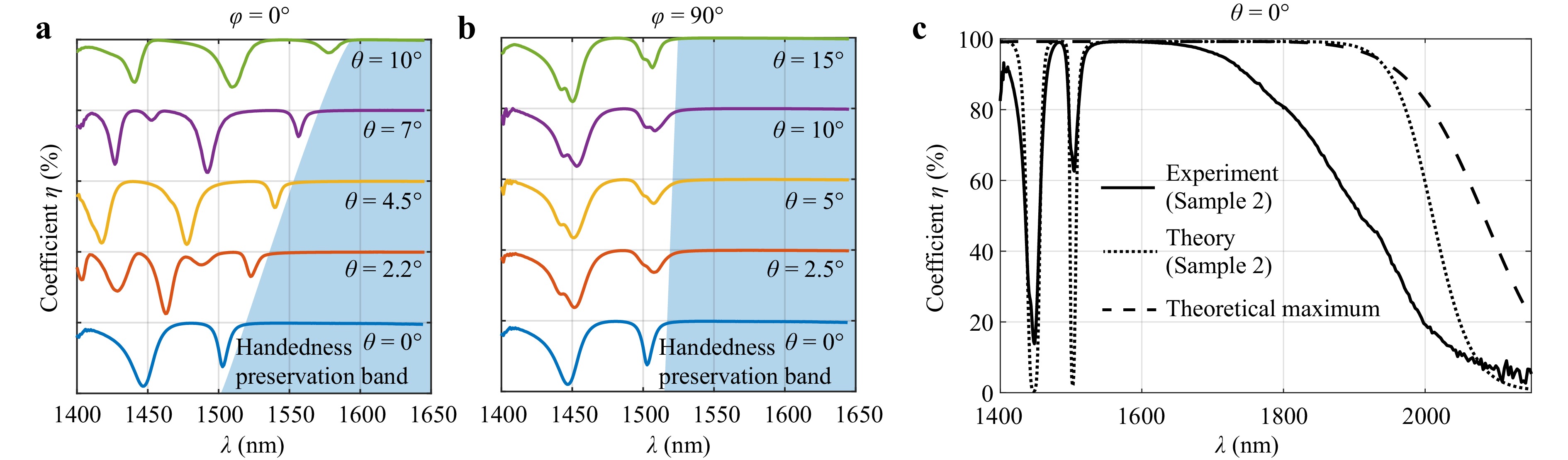
Fig. 5 Experiment. Spectral evolution of the handedness-preservation coefficient $ \eta $ for different incidence angles in the two incidence geometries: a $ \varphi = 0^{\circ} $ and b $ \varphi = 90^{\circ} $. c Spectra of $ \eta $ in a wide spectral range measured in the experiment on Sample 2 (solid line), reproduced numerically from the structure with geometric parameters of Sample 2 (dotted line) and calculated for the optimal structure considered in Fig. 1–3 (dashed line).
The extended theoretical and experimental spectral dependencies of $ \eta $ are shown in Fig. 5c for Sample 2 in comparison with the theoretically achievable optimal spectrum obtained for crystalline Si and the ideal geometry. The experimental spectrum for Sample 2 revealed that $ \eta $ reached 99% over a 150-nm-wide spectral range centred around 1,600 nm, with distinct dips corresponding to waveguide modes. For wavelengths greater than 1,650 nm, $ \eta $ decreased. The theoretical spectrum of Sample 2 reproduced the dips rather well; however, the spectral region where $ \eta $ approached unity was substantially broader, extending up to 1,850 nm. This discrepancy between the theory and experiment was attributed to the scattering losses present in the experimental setup, which were not accounted for in the theoretical model. Finally, the theoretical spectrum for an ideal structure, featuring a geometry optimised differently from that of Sample 2 and composed of high-quality crystalline silicon, represented the theoretical maximum for the handedness-preservation effect, establishing an upper bound for practical devices.
These observations demonstrate that the handedness-preserving functionality of the mirror is robust against moderate angular deviations and remains effective across both excitation geometries, thus confirming the stability of the design under different illumination conditions.
-
Next, we describe the above effect by considering a model structure consisting of an anisotropic layer with an effective dielectric permittivity $ \varepsilon_x = \varepsilon_\perp $ and $ \varepsilon_y = \varepsilon_\parallel $ lying on a perfect mirror ($ \varepsilon_m=-\infty $). For this model structure, the amplitude reflection coefficients $ r_{xx} $ and $ r_{yy} $ for a normally incident plane wave can be expressed as follows:
$$ r_{xx} = -\dfrac{1+\dfrac{i}{\sqrt{\varepsilon_\perp}}\tan{\left(k_0\sqrt{\varepsilon_\perp}h_{{\rm{gr}}}\right)}}{1-\dfrac{i}{\sqrt{\varepsilon_\perp}}\tan{\left(k_0\sqrt{\varepsilon_\perp}h_{{\rm{gr}}}\right)}} $$ (8) $$ r_{yy} = \dfrac{1-i\sqrt{\varepsilon_\parallel}\cot{\left(k_0\sqrt{\varepsilon_\parallel}h_{{\rm{gr}}}\right)}}{1+i\sqrt{\varepsilon_\parallel}\cot{\left(k_0\sqrt{\varepsilon_\parallel}h_{{\rm{gr}}}\right)}} $$ (9) The condition for the anisotropic layer to function as a handedness-preserving mirror, $ r_{xx}+r_{yy} = 0 $, is now equivalent to
$$ \dfrac{\tan{\left(k_0\sqrt{\varepsilon_\parallel}h_{{\rm{gr}}}\right)}}{\sqrt{\varepsilon_\parallel}}\cdot\dfrac{\tan{\left(k_0\sqrt{\varepsilon_\perp}h_{{\rm{gr}}}\right)}}{\sqrt{\varepsilon_\perp}} = -1 $$ (10) By taking the effective dielectric permittivities from the FMM-based homogenisation procedure as $ \varepsilon_\perp = 1.40 $ and $ \varepsilon_\parallel = 5.37 $, we can easily verify that condition (10) is approximately satisfied within the handedness-preservation band.
As mentioned in the Theory section, one option to implement a reflective surface such that its reflection matrix takes the form of (7) is the use of a homogeneous anisotropic layer with in-plane anisotropy. Although achieving a constant phase shift of $ {\text{π}} $ between the reflection coefficients $ r_{xx} $ and $ r_{yy} $ is possible at a single wavelength, maintaining this condition over a broad spectrum while ensuring that both reflection amplitudes remain near unity is exceptionally demanding. This necessitates an anisotropic material with an anomalous dispersion of its ordinary and extraordinary permittivities and a constant difference between them (see Supplementary Material Figure S6). Owing to this requirement, the successful selection of a suitable anisotropic material is highly unlikely.
Multilayer stacks of anisotropic materials may offer another alternative solution. Following the design proposed by Pancharatnam40, commercial quarter- and half-wave plates with extremely flat retardance in transmission over a broad spectral range have been demonstrated. An example is ‘Thorlabs Superachromatic Wave Plates’, which consist of three quartz and three magnesium fluoride (MgF2) plates that are optically cemented to maximise transmission and are carefully aligned to minimise the wavelength dependence of retardance41. A combination of such a broadband quarter-wave plate with an integrated mirror deposited on one of its surfaces can function as a handedness-preserving mirror. To compare its characteristics with those of our mirror, we simulated the above-mentioned quarter-wave plate placed in front of a broadband metallic mirror (for details, see Supplementary Material and Fig. S7a, b). As expected, this approach provides an extremely broadband operation with a spectral bandwidth that is approximately five times larger than that of our design. However, it does not offer advantages in terms of reflectivity, exhibiting a reflectance of only approximately 80%, which is similar to the experimentally obtained values but significantly lower than the theoretically predicted values for our design. Unlike our structure, the imperfect reflectance of the quarter-wave plate-based mirror is caused by, among other factors, losses (according to41, the sum of the reflection and transmission coefficients is less than 1) that sufficiently suppress the quality of such a mirror. Moreover, when comparing both designs of handedness-preserving mirrors, note that our grating-based design exhibits a substantial advantage in stability with respect to the angle of incidence. The quarter-wave plate-based mirror operates primarily for normal incidence and exhibits a rapid degradation in retardance for incidence angles exceeding $ 3^{\circ} $. As mentioned earlier, the numerical simulations show that in our design, the mirror is nearly insensitive to variations in the angle of incidence within $ \pm 10^{\circ} $. A detailed comparison between handedness-preserving mirrors based on commercial wave plates and our design is presented in the Supplemental Material (Fig. S7c-f). An additional advantage of our design over mirrors based on commercial quarter-wave plates is its compactness. The thickness of the grating is 297 nm, and the total thickness of the structure including the Bragg mirror is approximately 2 $ \mu $m. In contrast, the thickness of a mirror based on a quarter-wave plate exceeds 5 mm. Moreover, our structure is fully compatible with integrated-circuit fabrication technologies and can be manufactured from a wide variety of materials.
An alternative design for a Bragg-mirror-based handedness-preserving mirror can be achieved by replacing the dielectric Bragg mirror with a metallic mirror, as the latter can provide 97% reflectance and high angular tolerance. In the Supplementary Materials, we demonstrate that an optimised geometry of the metallic mirror-based design supports handedness-preserving reflection over a spectral range from 1,350 to 2,100 nm (Fig. S4). Although this operating bandwidth is approximately 300 nm wider than that of the Bragg-mirror-based design, the co-handed reflectivity varies between 95% and 97%, as shown in Fig. S4d, which is less than 99% offered by the configuration considered in the Results section.
As mentioned in the Introduction section, an application of handedness-preserving mirrors is in the creation of Fabry-Perot resonators that support chiral electromagnetic modes6,26. Therefore, one or both mirrors must be partially transparent. In this perspective, handedness-preserving mirrors based on commercial quarter-wave plates42 as well as those on reflective metallic substrates are inappropriate candidates.
A Fabry-Perot resonator formed using anisotropic broadband handedness-preserving mirrors is shown in Figure S8. As shown in our recent publications6,26 and Supplementary Materials, such a resonator supports modes of both handedness; by selecting the appropriate gap size and angle between mirror orientations, we can easily adjust the frequency of the Fabry-Perot mode to any value within the handedness-preservation band of the mirrors. This capability fundamentally distinguishes Fabry-Perot resonators based on anisotropic handedness-preserving mirrors from those utilising low-symmetry handedness-preserving mirrors24,32, because the latter operate only within a narrow spectral range. As mentioned previously, the narrowband functionality of low-symmetry mirrors originates from their resonant nature.
Finally, as demonstrated in Ref. 6, the resonant frequency of the Fabry-Perot resonator based on a pair of anisotropic handedness-preserving mirrors is highly sensitive to the macroscopic dielectric parameters of the material placed between them. The presence of chiral modes over a wide spectral range enables chiral sensing by monitoring the resonance frequency without requiring to measure circular dichroism or optical activity.
-
We theoretically derived and experimentally demonstrated a wideband all-dielectric mirror capable of preserving the handedness of circularly polarised light upon reflection in the near-infrared range. By combining a high-contrast, near-subwavelength one-dimensional dielectric grating with a Bragg mirror and optimising the design using a genetic algorithm, we achieved a structure that is robust against fabrication imperfections and tolerant to oblique incidence. Our experimental results demonstrate a wide spectral band in which over 98% of the reflected light preserves its handedness, with the total reflection coefficient reaching 80% under normal incidence. Moreover, the mirror retains high performance for incidence angles up to ±10°, underscoring its practical robustness. These findings demonstrate that the proposed mirror can function effectively as a reflective phase plate, providing a promising platform for Fabry-Pérot resonators and other photonic devices engineered for chiral light control and manipulation.
-
To theoretically study the optical behaviour of the Si grating on the Bragg mirror, we used a Fourier modal method in the scattering matrix form43, also known as rigorous coupled-wave analysis (RCWA)44. In the Fourier decomposition of electromagnetic fields, a one-dimensional set of Fourier harmonics in reciprocal space was selected. The total number of harmonics was set to $ N_g = 21 $, which ensured convergence of our numerical scheme. Consequently, a $ 4N_g \times 4N_g $-dimensional scattering matrix $ \boldsymbol{S}(\omega,k_\parallel) $, which contains the full optical information of our structure, was constructed. Here, $ \omega $ and $ k_\parallel $ denote the frequency of the electromagnetic oscillations and the in-plane wavevector, respectively.
The dielectric permittivities for crystalline Si and SiO2 used in the modelling were taken from Ref. 45 and 46.
-
The sample was fabricated on a single-crystalline Si (111) substrate. A Bragg mirror (DBR structure) was fabricated using e-beam deposition (Nexdep, Angstrom Engineering, Inc.). The thickness of the layer was controlled in situ using a calibrated quartz monitor. The DBR structure consisted of the following layers: 3$ \times $(87 nm Si/302 nm SiO2)/70 nm SiO2/236 nm Si. Grating manufacturing on the top silicon layer followed a standard process flow that included e-beam lithography and inductively coupled plasma etching. E-beam lithography was performed using a scanning electron microscope (JEOL JSM-7200F) equipped with a Xenos XPG2 pattern generator. Selective inductively-coupled plasma etching of the top silicon layer was performed using a CSAR AR-P 6200 (Allresist) patterned resist mask in the PlasmaPro 100 (Oxford Instruments) setup. The fabricated grating had a period of 463 nm with a filling factor of 0.36. The grating covered an area of 200 × 200 μm2. The thicknesses of the different layers forming the DBR structure were controlled using spectroscopic ellipsometry (SENresearch 4.0. Sentech Instruments).
-
Sample 2 was fabricated on a single-crystal quartz substrate. A Bragg mirror consisting of three consecutive pairs of Si and SiO2 layers was first deposited on a bare substrate using thermal e-gun deposition, with layer thicknesses of Si (110 nm) / SiO2 (280 nm) / Si (110 nm) / SiO2 (280 nm) / Si (110 nm). A 60 nm thick SiO2 layer and 290 nm thick Si layer were subsequently deposited on top to form the grating layer. Subsequently, an aluminium mask defining the grating pattern was fabricated using UV lithography and thermal e-gun deposition of a 100 nm thick Al film. This Al mask served as an etch mask for the subsequent inductively coupled plasma reactive-ion etching (ICP RIE) of the top Si layer in an SF6/CHF3 gas mixture. Finally, the Al mask was dissolved in a weak base solution, leaving a clean Si grating. The final structure covers an area of 4 × 4 mm2, with a grating period of approximately 650 nm and ribbon thickness of approximately 150 nm (Fig. 4a).
-
The experimental results reported in this paper were obtained using a resonant polarisation-reflection technique. The experimental setup is shown in Figure S5. All the measurements were performed at room temperature.
The broadband light of a halogen lamp was directed onto a 500-µm pinhole, and the resulting image was projected onto the sample using a lens-based optical system. Before reaching the sample, the beam was passed through an interference filter (IF, LBTEK) that selected wavelengths in the 1,100–2,100 nm range. A Glan-Taylor polariser (GP1, Thorlabs) combined with a quarter-wave Fresnel rhomb retarder (qwFR, Thorlabs) was used to generate the required circular polarisation state of the incident beam.
An iris diaphragm positioned in front of a plate beamsplitter (PB, Thorlabs, 10:90) limited the size of the light beam. Because the polarising optical system operated in a parallel light beam, and for all diaphragms used, an angular divergence of less than 0.25 degrees, the size of the iris diaphragm uniquely determined the angular aperture of the excitation beam focused by the lens positioned in front of the sample. To control the angle of incidence of the excitation beam, a beam splitter PB, enabled lateral displacement of the beam along the X-axis, mounted on a micrometre linear translation stage (Newport, M-462-X-M) with a shift accuracy of 10 microns. This accuracy was significantly smaller than the focal lengths of the lenses we used, which were several tens of millimetres, ensuring a high accuracy in determining the beam incidence angle. To prevent the shifting of the focus spot when the beam was translated in the X-direction, we placed the sample, a handedness-preserving mirror, on a precision XYZ translation stage with the possibility of rotation around the Z axis, and the position of the focal spot on its surface was monitored using an optical camera (Imaging Source). The experimental spectra presented in Fig. 5 with excitation angles up to 7° were obtained with an angular aperture of 1°, and those for excitation angles greater than 7° were obtained with an angular aperture of 2.5°.
The reflected signal was passed back through a Fresnel rhomb retarder and a Glan-Taylor polariser (GP2, Thorlabs), enabling the measurement of the intensity distribution on a circular polarisation basis. The beam was then passed through an achromatic quarter-wave plate (qwP) and focused on the entrance slit of the spectrometer. A quarter-wave plate was used to suppress any residual polarisation effects introduced by the monochromator grating of the spectrometer. Spectral measurements were performed using an Andor SR-303i-B spectrometer coupled to a thermoelectrically cooled CCD camera (Andor DU 490A-1.7). The exposure time was 10 s, with count rates below 300 Kcps. The spectral resolution was 1.5 nm, and the error in measuring the DCP signal did not exceed 0.5%.
-
This study was supported by the Russian Science Foundation (grant No. 25-12-00454).

 DownLoad: