-
The electromagnetic (EM) spectrum between the microwave and far-infrared regions, which is known as the terahertz (THz) frequency band (0.1-30 THz), is a spectral window that can facilitate rich scientific development1. It is well known that technological advances related to THz waves are not only driven by high-efficiency sources and detectors, but also decided by a variety of high-quality functional devices. Such devices (e.g., waveplates, beam splitters, convex/concave lenses, attenuators, and reflectors) are applied to modulate THz wavefronts, which play an important role in the application of THz waves. Currently, most of these devices are fabricated from high-density polyethylene, polytetrafluoroethylene, polymethylpentene, silicon, quartz, etc. When THz waves pass through functional devices made from such materials, their wavefronts will be deflected by gradual phase retardation inside predesigned media. However, such materials suffer from limited refractive indexes that are determined by permittivity and permeability within a narrow variation range. Therefore, traditional functional devices are bulky and must be sufficiently thick to generate propagation phase accumulation to realise the desired wave-manipulating functionality. Although THz waves have many promising applications ranging from biomedical and medical examinations, imaging, and environment monitoring to wireless communications2–5, existing limitations significantly hinder their application to the development of next-generation integrated/smart THz systems.
Metamaterials, which are artificial electromagnetic media consisting of periodic subwavelength microstructures, enable the functionality of modulating EM waves with tailored properties because their microstructures can be tuned with arbitrary values of electric permittivity and magnetic permeability. The major appeal of metamaterials lies in their ability to exhibit unprecedented EM properties that are impossible to achieve using naturally occurring materials. Such properties facilitate the fabrication of left-handed materials and negative-refractive-index materials6, 7. Previous works have demonstrated that metamaterials can be widely applied to the realisation of superlenses8, EM cloaks9, chiral media10, 11, etc. It should be noted that metamaterials enable these unprecedented functionalities based on subwavelength structures, rather than their constitutive materials. In contrast, metacomposites (random nanocomposites)12–20 exhibit unique properties such as negative permittivity and/or permeability based on their compositions and microstructures. Although EM metamaterials have achieved significant success, most metamaterial-based devices are still bulky in size and suffer from fabrication difficulties. To overcome these shortcomings, metasurfaces, which are the two-dimensional counterparts of metamaterials, have been developed. Metasurfaces typically consist of planar antennas that induce predetermined EM responses. These antennas are made of metals or traditional high-refractive-index dielectrics that can be easily fabricated using standard fabrication processes. Additionally, metasurfaces with the functionality of manipulating EM waves are dependent on abrupt phase changes at planar antenna interfaces, meaning the thickness of a metasurface is typically much smaller than the incident wavelength. Metasurfaces can locally control the wavefronts of EM waves at subwavelength resolutions, leading to various practical applications such as the metalens21–26, waveplates27, 28, vortex beam generators29–33, beam steering34, 35, and holograms36–40. The ultrathin nature of metasurfaces, their ease of fabrication, and subwavelength resolution for manipulating of EM waves make metasurfaces ideal candidates for THz device miniaturisation (ultra-compact THz devices) and system integration.
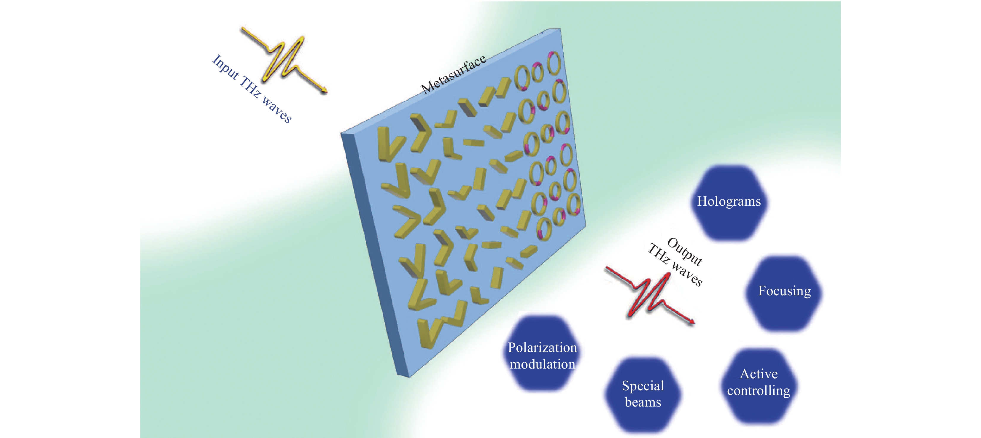
In this paper, we present an overview of metasurface-based wavefront-modulation devices in the THz region, including the planar metalens, holograms, arbitrary polarisation control, special beam generation, and active metasurface devices, which are illustrated schematically in Fig. 1. In “Principles of metasurfaces”, the working principles of metasurfaces for manipulating linearly polarised (LP) and circularly polarised (CP) EM waves will be introduced. In “Metasurfaces for focusing”, we review a variety of planar metalenses with different functions (e.g., spin-selected metalens, broadband metalens, spin-insensitive metalens, polarisation-controllable metalens, and imaging). In “Metasurfaces for generating holograms”, recent advancements in metasurfaces for generating holograms in the THz band will be introduced. In “Metasurfaces for controlling polarisation”, THz polarisation manipulation using polarisation rotators and polarisation convertors realised by metasurfaces will be discussed. In “Metasurfaces for generating special beams”, we review special beam generation based on metasurfaces. In “Metasurfaces for actively manipulating THz waves”, we review THz active metasurface devices. Finally, “Conclusions and outlook” concludes this review and presents perspectives on future applications in this research field.
-
Generally, metasurfaces in the THz region are divided into two categories: one is associated with antenna resonance while the other is based on the Pancharatnam-Berry phase (or geometric phase). The former type, which is used for realising desired phase changes, is related to the delicate design of the antenna geometry (e.g., V-shaped antennas with different arm lengths and opening angles for manipulating LP waves). The latter type is typically related to anisotropic antennas with identical structures, but different in-plane orientations (for manipulating CP waves). In this section, we summarise the physical principles of these two types of metasurfaces.
-
Traditional methods for reshaping the wavefronts of EM waves are dependent on various lenses (e.g., waveplates, convex/concave lenses, and attenuators) that can generate gradual phase accumulations along an optical path. When EM waves propagate at an interface between two different media, the reflection/refraction properties are governed by Snell’s law. It can be concluded that the angle of reflection is equal to the angle of incidence, whereas the angle of refraction is different from the angle of incidence, but obeys a fixed relationship. Recently, Yu et al. proposed a novel approach41 to manipulating the wavefronts of EM waves and breaking the constraint of the traditional Snell’s law (actually, the concept of a metasurface can be traced back even earlier42). By introducing an abrupt phase delay (phase discontinuity) at the interface between two media, the laws of reflection and refraction can be revisited according to Fermat’s principle. As shown in Fig. 2a, if a light beam incident from point A propagates to point B via two paths, the light beam will pass through the interface with a fixed phase gradient
$\left({{d\Phi }}/{{dx}}\right)$ and Snell’s law of refraction can be written as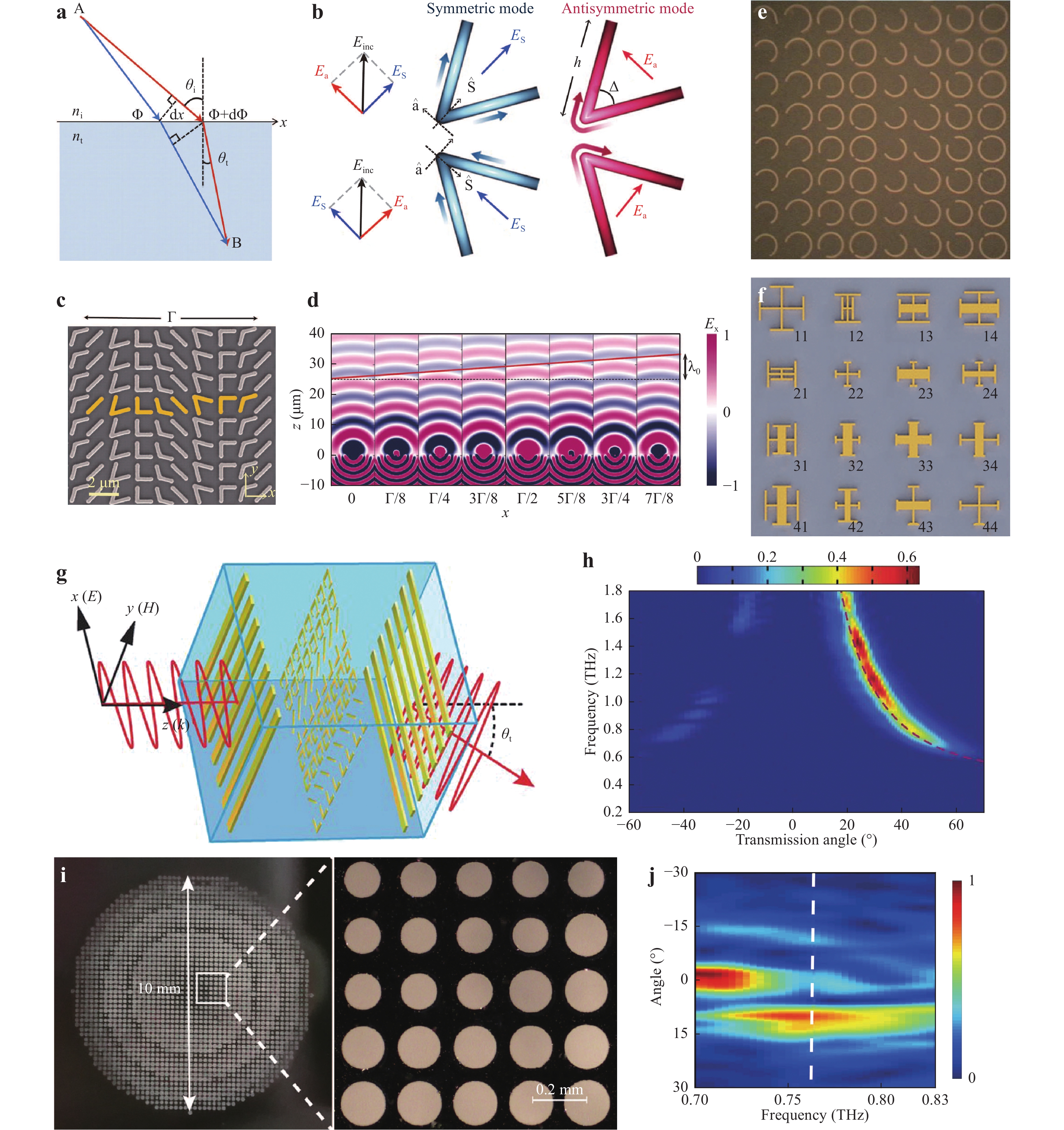
Fig. 2 Metasurfaces for manipulating LP EM waves.
a Schematics used to derive the generalised Snell’s law41. b V-shaped antenna for supporting symmetric and antisymmetric modes41. c Typical metasurfaces consisting of V-shaped antennas with different profiles, orientations, and flare angles41. d Calculated electric field distribution beyond a metasurface41. e and f Two types of gradient-index metasurfaces composed of C-shaped split-ring resonators (SRRs) with different orientations43 and flare angles, and cross-shaped SRRs with different sizes46. g and h Enhanced efficiency of beam deflection based on metasurfaces and gratings49. i and j Beam deflector with highly efficient transmission57. Images reprinted with the following permissions: a41, b41, c41, d41 from AAAS; e43 from John Wiley and Sons; f46 from IEEE; g49, h49 from AAAS; i57, j57 from John Wiley and Sons.$${n_t}\sin {\theta _t} - {n_i}\sin {\theta _i} = \frac{\lambda }{{2{\text π} }}\frac{{d\Phi }}{{dx}}$$ (1) where λ is the working wavelength. After introducing the phase gradient, Snell’s law of reflection is governed as follows:
$$\sin {\theta _r} - \sin {\theta _i} = \frac{\lambda }{{2{\text π} {n_i}}}\frac{{d\Phi }}{{dx}}$$ (2) Both Eqs. 1 and 2 are defined as the generalised Snell’s law, providing an approach to manipulate EM waves with multiple degrees of freedom.
Realising the desired phase gradient is of great importance because an antenna can only modulate incident waves with a fixed phase profile. Yu et al. designed V-shaped antennas with different opening angles, orientations, and arm lengths to modulate phase over a 2π range (see Fig. 2b). Therefore, a phase gradient can be obtained by introducing supercell-based structures (see Fig. 2c) to mimic the generalised Snell’s law. As shown in Fig. 2d, for the normal incidence of an x-polarised light beam, a beam with cross-polarisation (y-polarised light beam) is transmitted through the interface. Planar V-shaped antenna structures that can flexibly manipulate the wavefronts of EM waves are defined as metasurfaces. In addition to V-shaped metasurfaces, other types of metasurfaces consisting of C-shaped SRRs (see Fig. 2e), cross-shaped SRRs (see Fig. 2f), and U-shaped SRRs with different sizes and shapes have also been proposed to control the wavefronts of LP EM waves43–48.
Despite significant progress in terms of realising the generalised Snell’s law, the aforementioned metasurfaces suffer from low conversion efficiency, which is defined as the ratio between the power with cross-polarisation and the incident power. One approach to enhancing conversion efficiency is to design multilayered metasurfaces49–54. As shown in Fig. 2g, a multilayered structure consists of two-layered orthogonal metal gratings and a single-layer metasurface. The conversion efficiency is greater than 60% at an anomalous refraction angle of 24° based on interference between multiple polarisation couplings in the Fabry-Pérot-like cavity (see Fig. 2h). In addition to multilayered metal-based metasurfaces, metasurfaces consisting of dielectric rods with different sizes and shapes can also enable high conversion efficiency. The mechanisms behind the high efficiency of all-dielectric metasurfaces are believed to be antireflection coatings55 and Mie resonances56–59. For example, Yang et al. designed a Huygens’ metasurface consisting of low-index (air) holes in a high-index (silicon) wafer, as shown in (Fig. 2(i))57. The response of this metasurface is governed by electric and magnetic Mie resonances, resulting in a high conversion efficiency of up to 84.7% (see the beam deflector in Fig. 2j). A Huygens’ metasurface composed of non-uniform dielectric resonator antennas on a metal ground plane also enables high conversion efficiency (approximately 80%) based on resonance enhancement60. An all-dielectric KTiOPO4 (Huygens’) metasurface was also reported by Tian et al. and a THz beam deflector with an efficiency of 80% was numerically demonstrated61. Additionally, Zhao et al. designed a two-layered high-efficiency Huygens’ metasurface and the corresponding efficiency of anomalous refraction was calculated to be 66%53.
In addition to phase modulation, resonance-type metasurfaces can also manipulate the amplitudes of EM waves. The simultaneous control of phase and amplitude has been demonstrated by carefully designing the geometrical configurations and accurately controlling the angular orientations of a C-shaped antenna-based metasurface62. A dual-layered metasurface consisting of metallic C-shaped SRRs (in the top layer) and complementary SRRs (in the bottom layer) can independently manipulate both phase and amplitude at two THz wavelengths63. Additionally, approaches to the simultaneous control of phase and amplitude have been extended to THz surface plasmons, leading to the development of an efficient meta-coupler for complex surface plasmon launching64.
-
Unlike the manipulation of LP EM waves based on gradient-index metasurfaces, geometric metasurfaces have been proposed (Huang et al., 2012) to harness CP EM waves. Geometric metasurfaces typically consist of anisotropic antennas with different in-plane orientations, but identical shapes (see Fig. 3a, b). When incident CP (e.g., right-hand CP (RCP)) EM waves interact with an antenna (see Fig. 3a), the transmitted waves can be represented as follows:
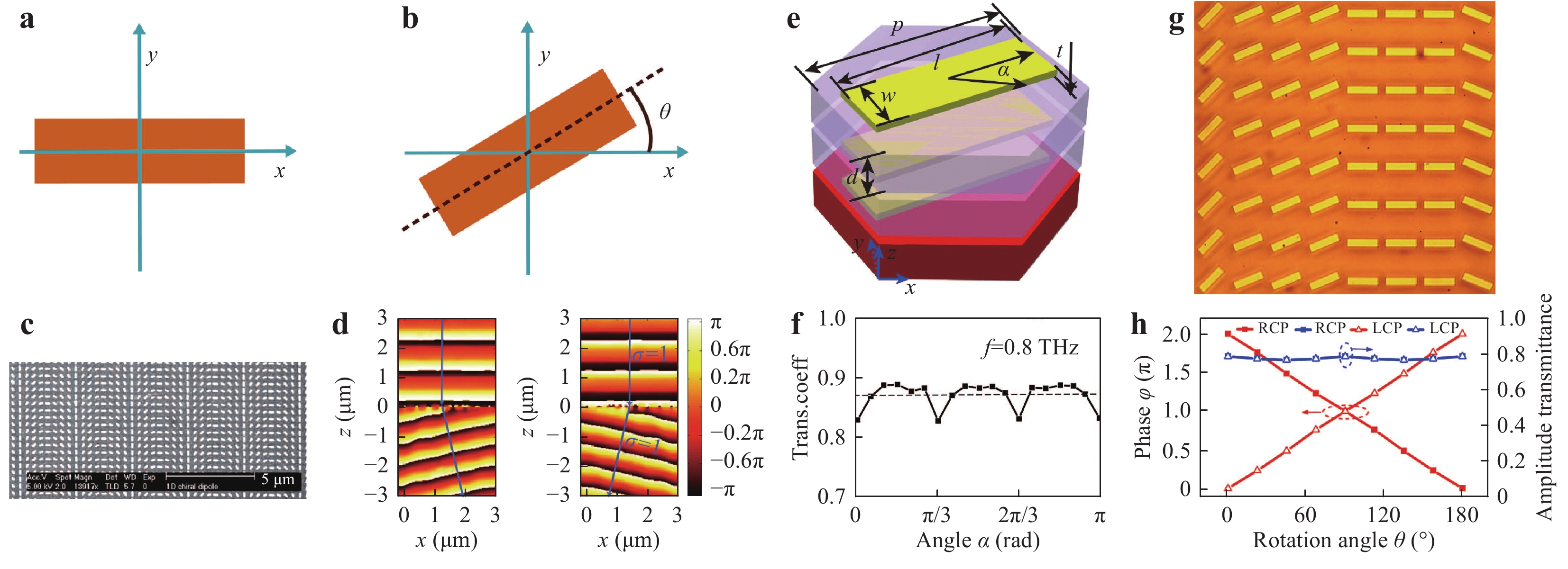
Fig. 3 Geometric metasurfaces for manipulation CP EM waves.
a and b Schematics of the working principles of the geometric metasurfaces. c and d Scanning electron micrscopy image of a geometric metasurface and helicity-dependent beam deflection under the normal incidence of CP EM waves65. e and f Schematics and efficiency of multilayered geometric metasurfaces68. g and h Optical image and efficiency of dielectric geometric metasurfaces69. Images reprinted with the following permissions: c65, d65 from ACS; e68, f68, g69, h69 from The Optical Society.$$\begin{split}{E_{out}} \propto J(\varphi )E_{in}^{RCP} =& \left[ {\begin{array}{*{20}{c}} {{e^{i\varphi /2}}}&0 \\ 0&{{e^{ - i\varphi /2}}} \end{array}} \right]\left[ {\begin{array}{*{20}{c}} 1 \\ i \end{array}} \right] \\=& \cos \frac{\varphi }{2}\left[ {\begin{array}{*{20}{c}} 1 \\ i \end{array}} \right] + i\sin \frac{\varphi }{2}\left[ {\begin{array}{*{20}{c}} 1 \\ { - i} \end{array}} \right]\end{split}$$ (3) where
$J(\varphi )$ is the Jones matrix for deducing the functionality of an anisotropic antenna (see Fig. 3a).It should be noted that transmitted EM waves consist of two components: co-polarised (non-converted) EM waves and cross-polarised (converted) EM waves. The conversion efficiency of converted EM waves depends on the phase retardation (φ) between the long and short axes. When RCP EM waves pass through a rotated antenna (antenna rotated counter-clockwise by an angle of θ (see Fig. 3b)), the transmitted waves can be represented as:
$${E_{out}} \propto J_{(\varphi )}^{(\theta )}\left[ {\begin{array}{*{20}{c}} 1 \\ i \end{array}} \right] = \left[ {\begin{array}{*{20}{c}} {\cos \dfrac{\varphi }{2} + i\sin \dfrac{\varphi }{2}\cos 2\theta }&{i\sin \dfrac{\varphi }{2}\sin 2\theta } \\ {i\sin \dfrac{\varphi }{2}\sin 2\theta }&{\cos \dfrac{\varphi }{2} - i\sin \dfrac{\varphi }{2}\cos 2\theta } \end{array}} \right]\left[ {\begin{array}{*{20}{c}} 1 \\ i \end{array}} \right] = \cos \dfrac{\varphi }{2}\left[ {\begin{array}{*{20}{c}} 1 \\ i \end{array}} \right] + i\sin \dfrac{\varphi }{2}{e^{i2\theta }}\left[ {\begin{array}{*{20}{c}} 1 \\ { - i} \end{array}} \right]$$ (4) where
$J_{(\varphi )}^{(\theta )}$ is the Jones matrix for deducing the functionality of a rotated antenna (see Fig. 3b). Here, the transmitted electric field also contains two components: non-converted EM waves and converted EM waves. However, converted light acquires an abrupt phase of 2θ induced by the rotated antennas. Therefore, this abrupt phase is known as a geometric phase or Pancharatnam-Berry phase. An antenna can be considered as an anisotropic scatterer that can convert a portion of incident CP EM waves into the opposite helicity with an abrupt phase.Fig. 3c presents a typical structure of a geometric metasurface consisting of anisotropic antennas with identical shapes, but different in-plane orientations65. Because the abrupt phase is solely dependent on the orientations of dipole antennas (anisotropic antennas), rather than their spectral responses, the phase discontinuity induced by the rotated dipole antennas is dispersionless, resulting in a broadband response for manipulating the wavefronts of EM waves. Under the illumination of left-hand CP (LCP)/RCP EM waves, the phase gradient of the converted portion is ± dφ/dx, where ‘+’ and ‘−’ are dependent on the helicity of the incident EM waves. Therefore, a helicity-dependent deflection phenomenon is generated under illumination from LCP/RCP EM waves, as shown in Fig. 3d. This approach can also be extended into the THz near-field region for manipulating anomalous surface waves66.
It should be noted that the conversion efficiencies of geometric metasurfaces increase with an increase of the number of antennas in each unit cell based on near-field coupling between the antennas in each unit cell67. When multilayered geometric metasurfaces are stacked (e.g., three-layered metasurfaces shown in Fig. 3e), the average conversion efficiency is as high as 76% (see Fig. 3f), leading to a high-efficiency metasurface for THz wavefront manipulation68. Unlike multiple-antenna metasurfaces and multilayered metasurfaces, all-dielectric geometric metasurfaces (see Fig. 3g, h) can also enable high operating efficiency for manipulating CP EM waves based on the resonance effect69 and coherence effect70, 71.
-
As indispensable tools, lenses have been widely exploited in various scientific communities (e.g., imaging, communication, and detection). Conventional lenses exhibit curved shapes that can reshape the wavefronts of EM waves with phase retardation, but require large and bulky shapes, significantly hindering the development of system integration. Metasurface-based lenses, which are referred to as metalenses, can abruptly modulate the phases of EM waves in the sub-wavelength range, significantly reducing the required thickness of lenses. Based on the unprecedented capabilities of metasurfaces for the local manipulation of the intensity, phase, and polarisation of EM waves, metalenses provide a series of unique functions that are difficult or impossible to achieve using conventional lenses.
Because the concept of metasurfaces provides a robust platform for controlling the wavefronts of EM waves, the function of a lens with a convex phase profile can be easily realised. For example, Fig. 4a presents a schematic of a THz metalens that can focus x-polarised incident THz waves into a y-polarised focal point. To focus incident LP THz waves, the planar metalens has a phase profile defined as follows72:
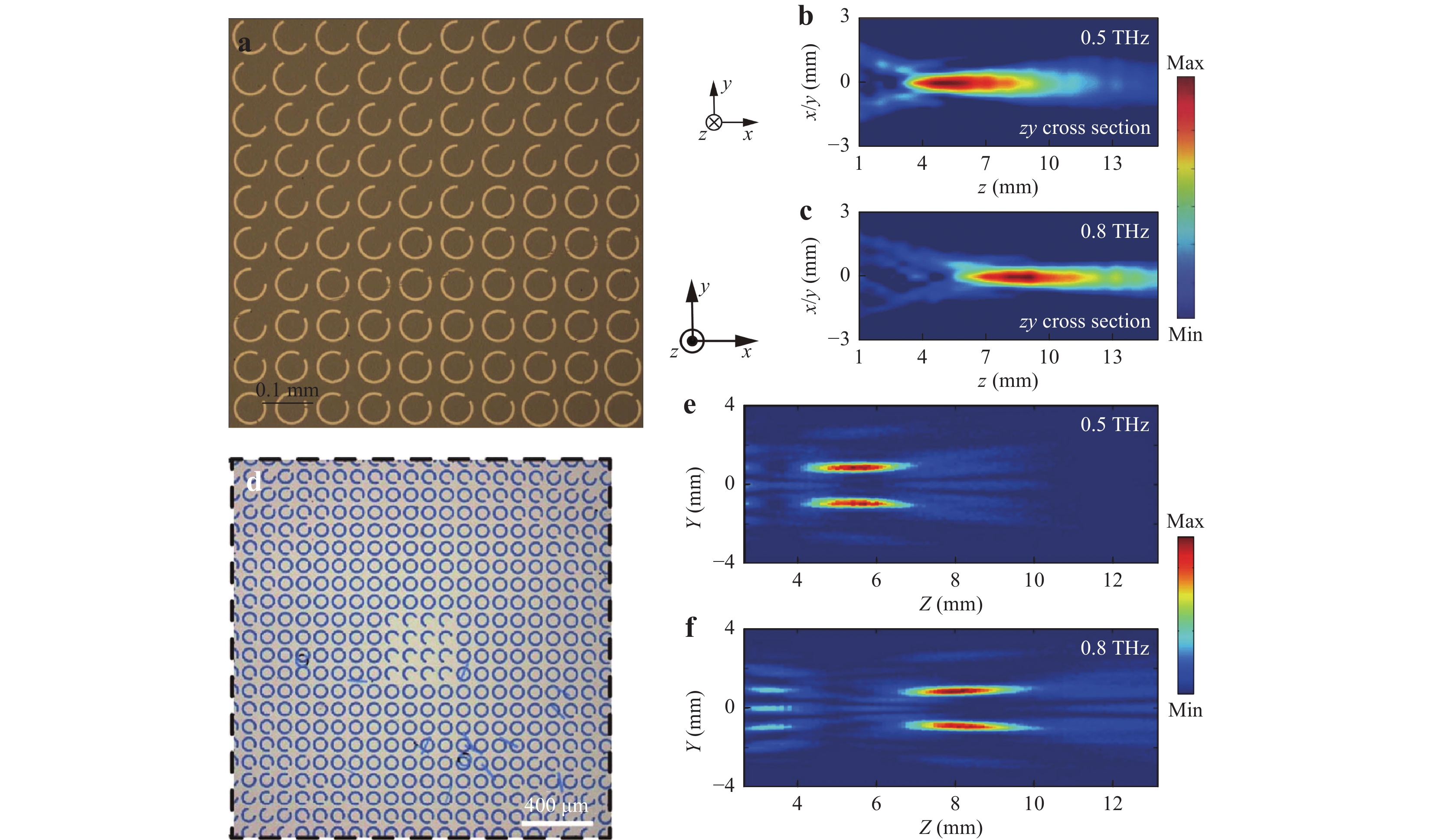
Fig. 4 Metalenses with one focal point and multiple focal points.
a Optical image of a metalens with a single focal point72. b and c Measured results of electric field distributions at 0.5 and 0.8 THz, respectively, under x-polarised normal incidence72. d Optical image of a metalens with multiple focal points74. e and f Measured results of electric field distributions at 0.5 and 0.8 THz, respectively, under x-polarised normal incidence74. Images reprinted with the following permissions: a72, b72, c72 from John Wiley and Sons; d74, e74, f74 from Springer Nature.$$\varphi (x,y) = \frac{{2{\text π} }}{\lambda }(\sqrt {{x^2} + {y^2} + {f^2}} - |f|)$$ (5) where
$\lambda $ is the working wavelength and f is the focal length. Under the illumination of x-polarised THz waves, a y-polarised focal point can be observed after the metalens, as shown in Fig. 4b, c. A THz flat lens comprised of C-shaped SRRs exhibits broadband focusing properties ranging from 0.5 to 0.9 THz. Additionally, Jia et al. reported a dilectric metalens (Huygens’ metasurface) consisting of periodically arranged sub-wavelength silicon cross resonators for focusing LP incident THz waves into a focal point with a focusing efficiency of 24%73.To demonstrate the versatility of C-shaped metalenses, He et al. designed a THz ultrathin multi-foci metalens (see Fig. 4d) based on the Yang-Gu amplitude-phase retrieval algorithm74. Under the incidence of LP THz waves, four focal points can be observed, as shown in Fig. 4e, f. This metalens also exhibits broadband performance ranging from 0.3 to 1.1 THz. By using cross-shaped structures with different sizes to manipulate the wavefronts of THz waves, a polarisation-insensitive multi-foci metasurface mirror can be realised75. Additionally, spin-dependent multi-foci metalens76 and holographic metasurface mirrors77 for generating multiple THz focal points have also been proposed in recent years.
Focusing efficiency, which is defined as the ratio of the intensity of the focal point over the incident intensity, plays a vital role in the evaluation of metalens performance. To enhance focusing efficiency, a series of metalenses, including multilayered metalenses51, 78–81 and all-dielectric metalenses55, 57, 73, have been proposed and fabricated. As shown in Fig. 5a, a high-efficiency metalens has been designed based on a sandwiched structure (i.e., three layers of square aluminium cladding separated by polyimide spacers). This metalens can focus x-polarised plane waves into a focal point with a transmission efficiency greater than 45% based on Fabry-Pérot-like resonance (the corresponding electric field distribution is presented in Fig. 5b). Chang et al. designed a tri-layered metasurface-based lens with high focusing efficiency (68%). Their metalens exhibited diffraction-limited focusing at an operating frequency of 400 GHz79. For all-dielectric metalenses, focusing efficiency can reach as high as 54.9%57 and 61.3%55 by leveraging waveguide resonance and Mie resonance, respectively.
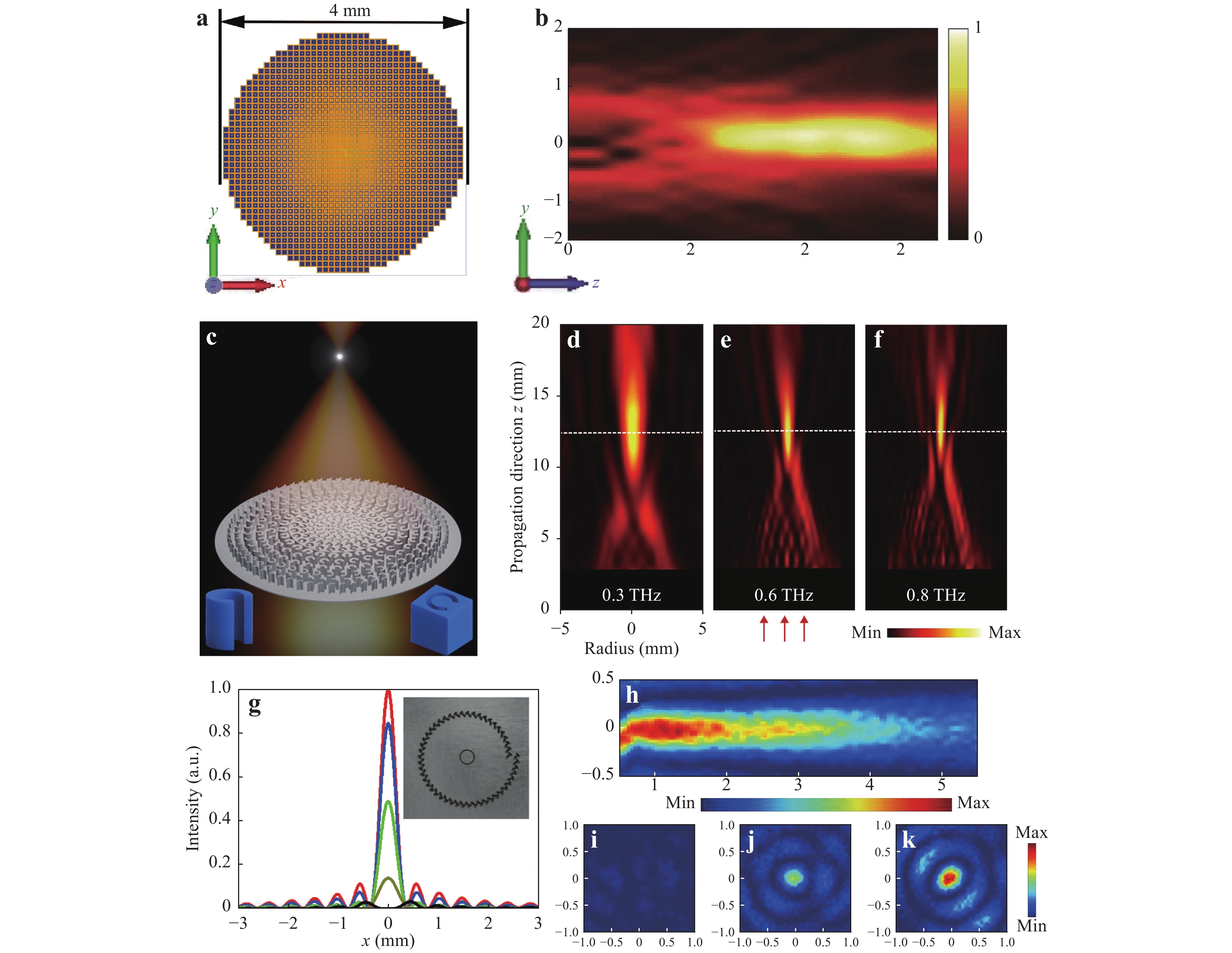
Fig. 5 Metalenses with high conversion efficiency, achromatic functionality, and superresolution functionality.
a Schematic of a high-efficiency metalens51. b Measured electric field distribution of the metalens under normal plane wave incidence at 0.95 THz51. c Schematic of a dielectric achromatic metalens consisting of two complementary structures83. d, e, and f Measured electric field distribution of the metalens under the illumination of RCP THz waves at 0.3, 0.6 and 0.8 THz, respectively83. g Normalized intensity distributions (in the x-axis) and optical image of a polarisation-controlled superfocusing metalens84. h Measured electric field distribution at 0.34 THz84. i, j, and k Measured electric field distributions of the metalens under the illumination of LCP, LP, and RCP THz waves, respectively, at focal planes84. Images reprinted with the following permissions: a51, b51 from John Wiley and Sons; c83, d83, e83, f83 from Science China Press; g84, h84, i84, j84 k84 from AIP Publishing.In addition to the high efficiency of metalenses, achromatic focusing is also essential for imaging. For traditional metalenses under the illumination of EM waves with multiple wavelengths, aberration effects occur as a result of material dispersion, leading to numerous focal points at different spatial positions and decreasing the performance of imaging and detection. To realise achromatic functionality, a conventional imaging system typically uses a multi-lens cascade to compensate for phase differences. It has recently been reported that chromatic aberrations can be eliminated in multi-wavelength or broad-bandwidth scenarios by using metalenses. Ding et al. designed a metalens consisting of C-shaped/C-slit structures with different opening angles that can focus THz waves at 400 and 750 μm to the same focal distance82. As shown in Fig. 5c, an all-dielectric metalens composed of C-shaped/inverse-C-shaped structures has been developed to realise achromatic focusing. Under the illumination of RCP THz waves, the focal lengths of focal points at 0.3, 0.6, and 0.8 THz are very similar, as shown in Fig. 5d-f. An achromatic metalens can work in a broad bandwidth range from 0.3 to 0.8 THz with a bandwidth coverage of 91% at the centre frequency83.
The resolution of imaging realised by metalenses is another crucial factor. Fig. 5g presents a schematic of a metalens that can generate a near-field focal point84. The measured electric field distribution is presented in Fig. 5h. The full width at half maximum of the focal point is 337 μm (approximately 0.38λ), demonstrating that the designed metalens enables high-resolution functionality in the near-field region. This metalens provides a tuneable intensity of the focal point by controlling the polarisation of incident THz waves. As demonstrated in Fig. 5i-k, the intensity of the focal point becomes stronger as the polarisation of the incident THz waves is switched from LCP to RCP. Here, the realisation of THz superfocusing can be attributed to the scattering of surface plasmon polaritons (SPPs) into free space with in-phase field superposition. Accordingly, a polarisation-independent high-numerical-aperture dielectric metalens and tri-layered metalens were designed by Chen et al. and Zhang et al., respectively, to perform sub-wavelength tight focusing85, 86.
Recently, metalenses have been reported as a promising technology for imaging. In 2013, Hu et al. proposed an ultrathin THz metalens (see Fig. 6a) composed of complementary V-shaped antennas for imaging87. Three letter patterns of ‘C’, ‘N’, and ‘U’ were used as imaging objects and these three letters were clearly displayed on an image plane (see Fig. 6b-d). Wang et al. reported spin-selected imaging based on a spin-selected metalens. The spin-selected metalens was designed based on the shift of wave vectors and can generate two helicity-dependent focal points. For predesigned letter patterns under the illumination of LCP/RCP THz waves, the revealed images are located at different positions, demonstrating the realisation of spin-selected imaging76. Accordingly, a high-efficiency metalens based on dual-layered metasurfaces was also proposed for imaging80. Furthermore, Zang et al. proposed a polarisation-controllable THz multi-foci metalens for polarisation-dependent imaging88. Fig. 6e presents a corresponding schematic in which two focal points with different polarisation orientations can be observed under the illumination of LP THz waves. As demonstrated experimentally, a y-polarised focal point can be observed at z = 3 mm, while the other x-polarised focal point is observed at z = 6 mm under the incidence of x-polarised THz waves. A polarisation-dependent sample was proposed to characterise lens imaging functionality and polarisation rotation capability simultaneously. As shown in Fig. 6f, g, when a polarisation-dependent sample is embedded in the region of the left focal point, the left capital letter ‘E’ is revealed. The ‘
$\exists $ ’ symbol on the right is observed when the sample is embedded in the region of the right focal point. Unlike traditional metalenses with limited focal depths, metalenses with extended focal depths have been designed and fabricated to enhance imaging depth89, 90. Fig. 6h presents a schematic of a metalens with extended focal depth and polarisation insensitivity. Under the illumination of LCP/RCP THz waves, there is a focal point with a main field distribution ranging from 10 to 20 mm (see Fig. 6i, j with a focal length of 10 mm), whereas the focal length for a traditional metalens in this scenario is only 4 mm. Additionally, an arrow-shaped sample was considered to demonstrate the characteristics of a metalens with an extended focal length. For the designed metalens with an extended focal length (see Fig. 6k-m), the arrow can be observed at z = 11 mm, z = 15 mm, and z = 19 mm, demonstrating the realisation of high-tolerance imaging. For a traditional metalens, only one arrow-shaped image can be observed when the arrow-shaped sample is placed at z = 6 mm, z = 10 mm, and z = 14 mm.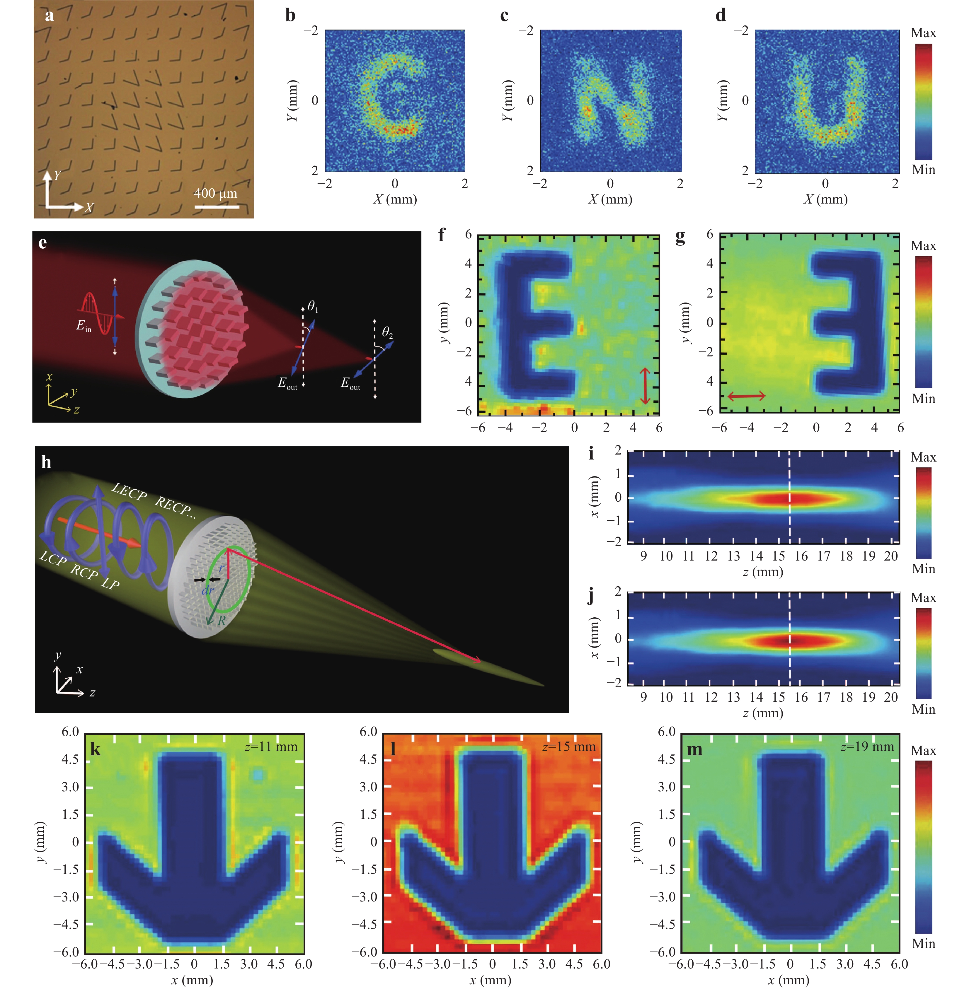
Fig. 6 Metalenses for imaging.
a Optical image of a metalens with a focal point87. b, c, and d Images of three letters (C, N, and U) after the metalens shown in a87. e Schematic of a THz multi-foci metalens with polarization-rotated points88. f and g Measured images when the designed imaging sample is embedded in the left and right focal points, respectively88. h Schematic of a polarisation-insensitive metalens with an extended focal depth89. i and j Measured electric field distributions of a metalens under the illumination of LCP and RCP THz waves89. k, l, and m Measured images of an arrow-shaped sample at z = 11 mm, z = 15 mm, and z = 19 mm89. Images reprinted with the following permissions: a87, b87, c87, d87, e88, f88, g88, h89, i89, j89, k89, l89, m89 from John Wiley and Sons. -
Holography can generate unique photographic images without the use of a lens. Unlike photographic images, which record variations in the intensity of light reflected from an object, holography records both the intensity and phase of light. Therefore, a hologram contains complete information regarding an object’s scattered waves, meaning it can generate vivid representations of images for the human eye. The traditional method for realising holograms is based on the interference between reference light and scattered waves from an object. Computer generated holograms, which are another approach to generating holograms, typically provide significant advantages compared to optical holograms because no real objects are required. A holographic image can be generated by calculating holographic interference patterns (phase information) and encoding them onto a surface structure or spatial light modulator (SLM). Because a metasurface can accurately manipulate the wavefronts of EM waves, metasurfaces are considered as ideal candidates for generating holograms. Compared to holographic technology based on SLMs, metasurface-based holograms, which are referred to as metaholograms, enable higher image quality and efficiency, superior broadband characteristics, and a wider field of view.
Fig. 7a presents a V-shaped metasurface for generating holograms87. The Gerchberg-Saxton iterative algorithm in the Fresnel domain is used to retrieve the phase profile of a phase-only hologram (e.g., the letter of ‘C’). Next, the phase distribution is encoded onto the metasurface by controlling the arm lengths and opening angles of the V-shaped structures. Under the incidence of LP THz waves, the image of the letter ‘C’ is observed one a plane at a distance of 4 mm from the metasurface, as shown in Fig. 7b. However, phase-only (or amplitude-only) holograms inevitably degrade image quality and resolution. To overcome this issue, broadband metaholograms based on amplitude-phase modulation have been developed in recent years91, 92. By simultaneously tailoring the amplitude and phase, the disadvantages of traditional phase or amplitude holograms can be overcome, leading to enhanced performance and resolution. Fig. 7c presents a metasurface with simultaneous amplitude and phase modulation for generating high-performance holograms. C-shaped SRRs with different rotation angles and opening angles are designed for amplitude and phase modulation. In Fig. 7d, under the illumination of x-polarised THz waves, a hologram reconstructed from letters of ‘T’, ‘J’, and ‘U’ can be clearly observed following the metasurface. As shown in Fig. 7e, another hologram with the same letters can be generated using a metasurface with only phase modulation. When comparing Fig. 7d, e, the resolution of the hologram generated with amplitude-phase modulation is greater than that of the phase-only hologram. In addition to the manipulation of EM waves in free space (far-field), metasurfaces can also be designed as plasmonic couplers for the excitation and modulation of SPPs. It has been reported that the amplitudes and phases of excited SPPs can be freely modulated by etching slit-pair resonators with predesigned orientations on a metal film, leading to polarisation-controlled SPP holography93.
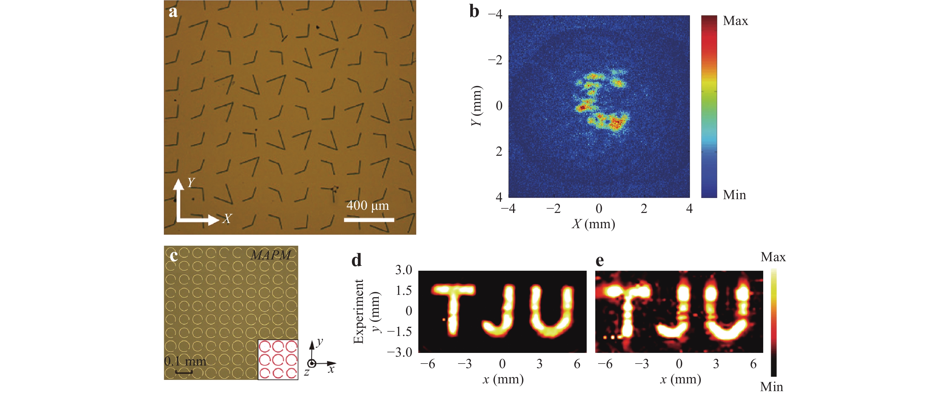
Fig. 7 THz meta-holograms for image reconstruction.
a Optical image of the metasurface for generating hologram87. b The measured result of the y-polarised electric distribution on the image plane87. c Optical image of the metasurface for generating hologram91. d The measured result of the y-polarised electric distribution (after the metasurface with simultaneous amplitude and phase modulation) on the image plane91. e The y-polarised electric distribution (after the metasurface with only phase modulation) on the image plane91. Images reprinted with the following permissions: a87, b87 from John Wiley and Sons; c91, d91, e91 from Springer Nature.For metaholograms, one of the most important performance indicators is information capacity. Recently, the concept of holographic multiplexing has been proposed and demonstrated to meet the growing need for improving the information capacity of holograms. Fig. 8a presents a specific metasurface structure for the generation of wavelength-multiplexed holograms. Each C-shaped subwavelength metallic antenna is used as a dual-colour wavefront modulator unit94. Under the illumination of x-polarised THz waves, two y-polarised letters of ‘C’ and ‘N’ are reconstructed at 0.5 and 0.63 THz, respectively (see Fig. 8b, c). Similar to wavelength-multiplexed holograms, polarisation introduces another degree of freedom that can be applied to improve the information capacity of holograms95, 96. Fig. 8d presents a schematic of reflective helicity-multiplexed metaholography. The metasurface for generating helicity-multiplexed holograms consists of periodic supercells in which two unit cells distributed in the diagonal direction are designed to manipulate RCP THz waves, while two unit cells distributed in the anti-diagonal direction are designed to modulate LCP THz waves. Therefore, this metasurface can independently tailor THz waves with different spin states. As shown in Fig. 8e, f, two images of ‘L’ and ‘R’ can be reconstructed at the same position under the illumination of LCP and RCP THz waves, respectively. Additionally, Zhao et al. designed a metahologram for multi-image hiding and seeking. Their metasurface consists of rod slit antennas and C-shaped slit antennas that are used to control CP and LP THz waves, respectively (see Fig. 8g)97. Under the illumination of x-polarised THz waves, the C-shaped slit antennas convert a potion of the incident THz waves into the y-polarised letter ‘H’ in channel 1 (see Fig. 8h). The rod slit antennas simultaneously convert the other portion of the incident THz waves into two helicity-dependent letters of ‘C’ and a mirrored ‘C’ in channels 2 and 3, as shown in Fig. 8i, j, respectively. In addition to wavelength- and polarisation-multiplexed metaholograms, metasurfaces can also be accurately designed for spatial multiplexing of holograms98, 99.
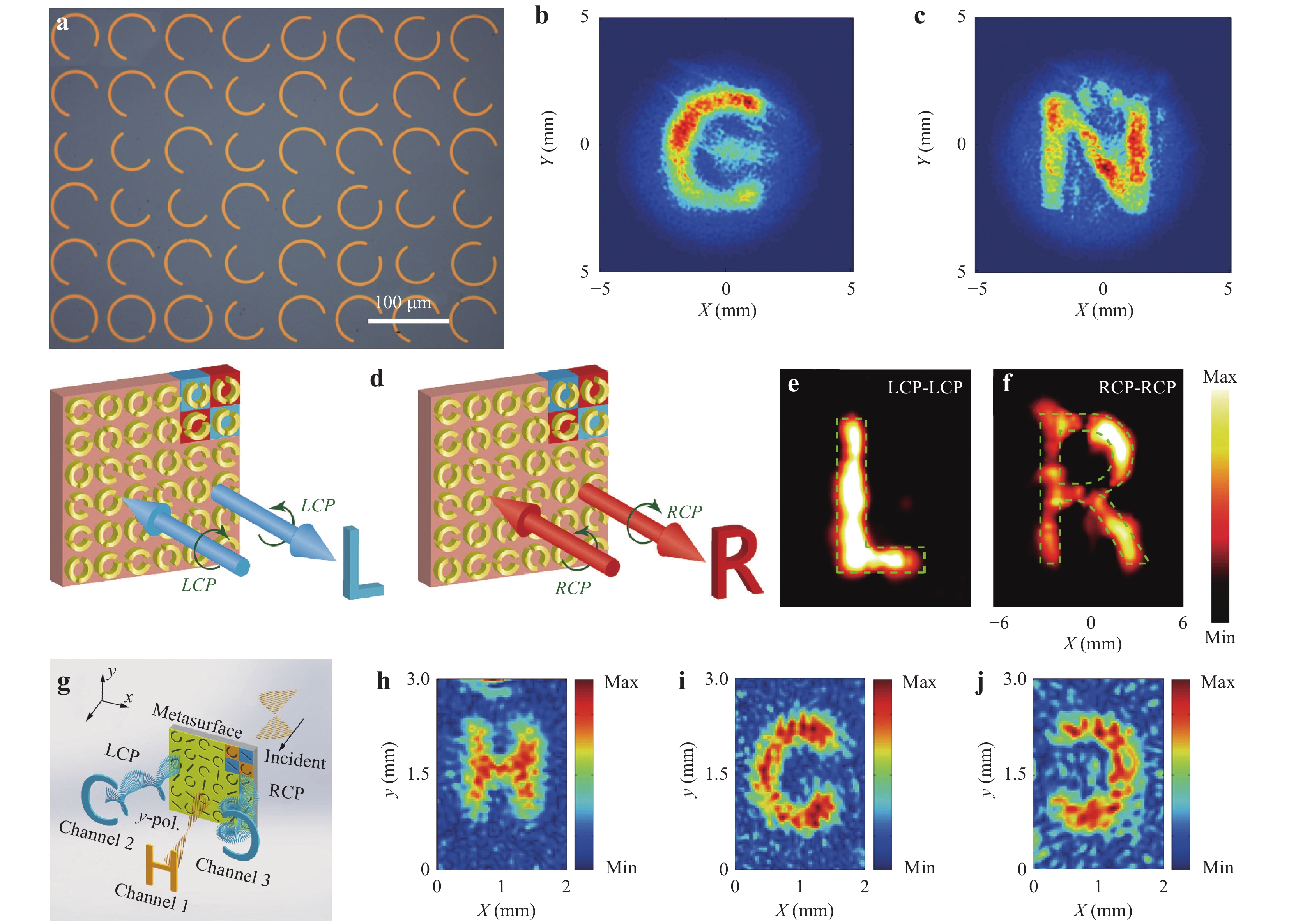
Fig. 8 Wavelength and polarisation-multiplexed metaholograms.
a Optical image of a metasurface for generating wavelength-multiplexed holograms94. b and c Measured results of y-polarized electric distributions on image planes at 0.5 and 0.63 THz, respectively94. d Schematics of reflective helicity-multiplexed metaholography: images ‘L’ and ‘R’ are reconstructed at the same position under the illumination of LCP and RCP THz waves95. e and f Measured results of LCP and RCP electric distributions on the same image plane, respectively95. g Schematic of an LP and CP multiplexed metasurface for generating multiple images97. h, i, and j Measured electric field distributions of transmitted fields Exy, ERL, and ELR in channels 1, 2, and 3, respectively97. Images reprinted with the following permissions: a94, b94, c94, d95, e95, f95 from Springer Nature; g97, h97, i97, j 97 from American Physical Society. -
Similar to phase and amplitude, polarisation is one of fundamental properties of EM waves. The manipulation of polarisation has found many useful applications in daily life, including polarised sunglasses, photography, and 3D display. Traditional polarisation manipulation is largely based on the birefringence, scattering, and dichroism realised by wave retarders, lenses, and spatial phase modulators, which are typically large and bulky. In this section, we focus on recent progresses related to ultra-thin metasurfaces for manipulating the polarisation of THz waves, including half-wave plates and quarter-wave plates.
-
LP EM waves can be considered as a superposition of LCP and RCP components with the same amplitude. When LP EM waves pass through materials with circular birefringence (e.g. half-wave plates), the polarisation angle of the output EM waves will be rotated based on the different refractive indices of the LCP and RCP components. Metasurfaces with carefully designed anisotropic meta-atoms provide unprecedented capabilities for mimicking circular birefringence, which has lead to the development of a plethora of ultrathin and ultra-compact THz half-wave plates49, 100–104. Fig. 9a presents a schematic of a reflective type of THz half-wave plate consisting of identical anisotropic rods along the diagonal direction49. Under the illumination of x-polarised THz waves, the reflected THz waves are mainly comparised of y-polarised component (cross-polarised THz waves), as shown in Fig. 9b. Such a high-efficiency (greater than 80%) THz half-wave plate can operate in a broad bandwidth ranging from 0.73 to 1.80 THz. Each of the anisotropic rods can be considered as a localized half-wave plate with its principal axis along the diagonal direction, meaning x-polarised THz waves can be completely converted into y-polarised THz waves. Additionally, dual- and tri-layered metasurfaces have been proposed to realise high-efficiency and broadband THz half-wave plates100-102. An all-dielectric single-layered metasurface can also obtain a high efficiency and broadband half-wave plate103. As shown in Fig. 9c, a high-efficiency and broadband THz half-wave plate has been designed based on a pair of rectangular silicon pillars. By controlling the orientation of each pillar and introducing a phase gradient, the cross-polarised component (with a maximum conversion efficiency of 67.5%) can be spatially separated over a space covering the range of 0.5-1.4 THz (see Fig. 9d). In addition to rotating the polarization of THz waves in a single channel, Zang et al. proposed an approach to realise an ultra-thin multi-channel THz half-wave plate104. A reflective-type metasurface (see Fig. 9e) was designed to reflect incident LP THz waves as four beams, where the polarisation of the reflected beams in each channel was modulated by a rotation angle with respect to the incident THz waves, resulting in a multi-channel half-wave plate. Under the incidence of x-polarised THz waves, the polarization states of reflected beams in horizontal channels are rotated with a rotation angle of π/4 with respect to the incident THz waves, whereas the rotation angle of polarisation in perpendicular channels is π/2, as shown in Fig. 9f-i. In fact, metasurface-based half-wave plates can be applied to design chiral metamaterials, leading to asymmetric transmission of THz waves. For example, Lv et al. have designed a bilayer chiral metasurface consisiting of orthogonally chained S-shaped metal-patterns, and such a metasurface enables the functions of half-wave plate and asymmetric transmission105. Furthermore, Rao et al. have presented an all-silicon metasurface with the functionality of half-wave plate to demonstrate the asymmetric transmission effect106. In addition, a hybrid THz metasurface embedded with VO2 (vanadium dioxide) was also designed for polarization manipulation and thermal-controlled chiral switching107.
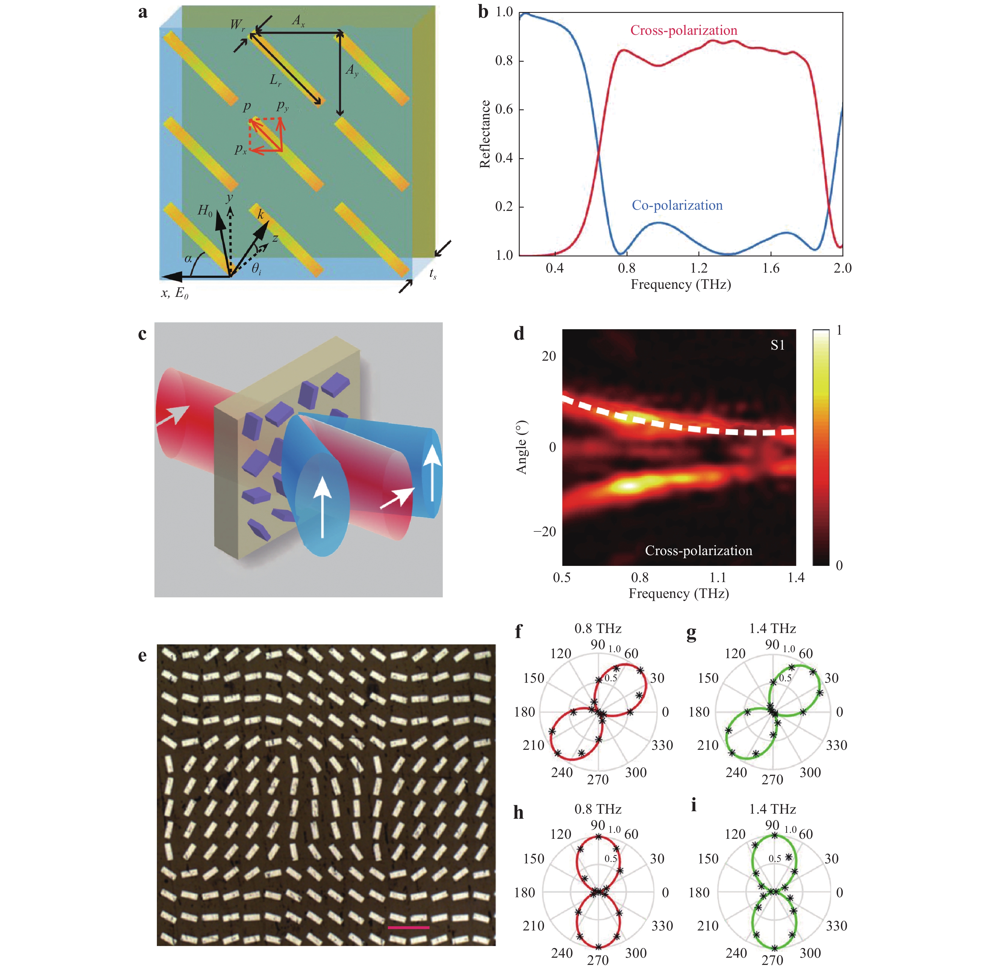
Fig. 9 THz half-wave plates.
a Schematic of a reflective type THz half-wave plate consisting of identical anisotropic rods along the diagonal direction49. b Measured co- and cross-polarized reflectance49. c Schematic of a THz all-dielectric metasurface half-wave plate103. d Measured cross-polarized transmission spectrum of the THz half-wave plate103. e Optical image of a THz half-wave plate104. f and g Simulated (solid curves) and experimentally measured (discrete asterisks) polarisation distributions in the horizontal channels at 0.8 and 1.4 THz, respectively104. h and i Simulated (solid curves) and experimentally measured (discrete asterisks) polarisation distributions in the perpendicular channels at 0.8 and 1.4 THz, respectively104. Images reprinted with the following permissions: a49, b49 from AAAS; c103, d103 from Chinese Laser Press; e104, f104, g104, h104, i104 from AIP Publishing. -
Polarisation convertors such as quarter-wave plates can also be realised based on birefringent effects, which can be conventionally generated by certain materials, including bulky crystals and polymers. It was recently reported that the thicknesses of quarter-wave plates can be significantly reduced to the subwavelength scale based on the use of metasurfaces. Fig. 10a presents a schematic diagram of a THz linear-to-circular/elliptical polarization convertor108 consisting of ultrathin aluminium SRRs (150-200 nm in thickness). There are two air gaps in the aluminium SRRs. By breaking the axial symmetry of these air gaps, linear-to-circular polarisation conversion can be realised (see Fig. 10b-e). For δx = 0 μm, the output THz beam is in the linearly co-polarised state (under the illumination of y-polarised THz waves). When the axial symmetry is broken (e.g. δx = 10, 20 μm), right-hand elliptically and CP THz waves are generated at 0.9 THz (see Fig. 10c, e). To enhance the working bandwidth further, a tri-layered metasurface was proposed to realise a broadband THz linear-to-circular polarisation convertor109. Such a highly flexible quarter-wave plate enables the desired response between 1.4 and 1.8 THz with a quasi-perfect RCP state based on lattice diffraction modes and the plasmon resonance induced by birefringence and phase compensation. By introducing SRRs and gratings into a single-layered metasurface, a broadband THz linear-to-circular THz polarization convertor (quarter-wave plate) in two broad frequency bands of 0.64 to 0.82 THz and 0.96 to 1.3 THz was developed110. Unlike the approach in Ref. 82 (without considering inter-unit-cell coupling), Zang et al. proposed a THz broadband linear-to-circular polarization convertor based on inter-unit-cell coupling111. As shown in Fig. 10f, the quarter-wave plate consists of two rectangle arrays of different size. Each rectangle array appears as a single-band quarter-wave plate and a broadband response (see Fig. 10g, h) is obtained via the dual-band superposition based on the coupling between two rectangles of different size. Additionally, a single-layered metasurface can enable the functionalities of both a half-wave plate and quarter-wave plate112, 113. As illustrated in Fig. 10i, an all-dielectric metasurface composed of silicon brick arrays enables the simultaneous excitation of dipole and quadrupole resonances that can heavily suppress backward scattering. Under the illumination of THz waves with polarisation along the diagonal direction, this metasurface can simultaneously operate as a quarter-wave plate at f1 and half-wave plate at f2 with transmission close to unity (see Fig. 10j). Based on the coupled mode theory, Chang et al. proposed and experimentally demonstrated off-resonance reflective metasurfaces realising linear-to-circular polarisation conversion. Their linear-to-circular polarisation convertor can operate over a full octave bandwidth with near-unity power conversion efficiency114. Additionally, Lee et al. proposed a dielectric-resonator metasurface for designing a broadband THz polarisation convertor to realise quarter- and half-wave mirrors. The bandwidth for a quarter-mirror is 0.63 THz (with a conversion efficiency of 92%) and that for a half-wave mirror is 0.65 THz (with a conversion efficiency of 96%)115.
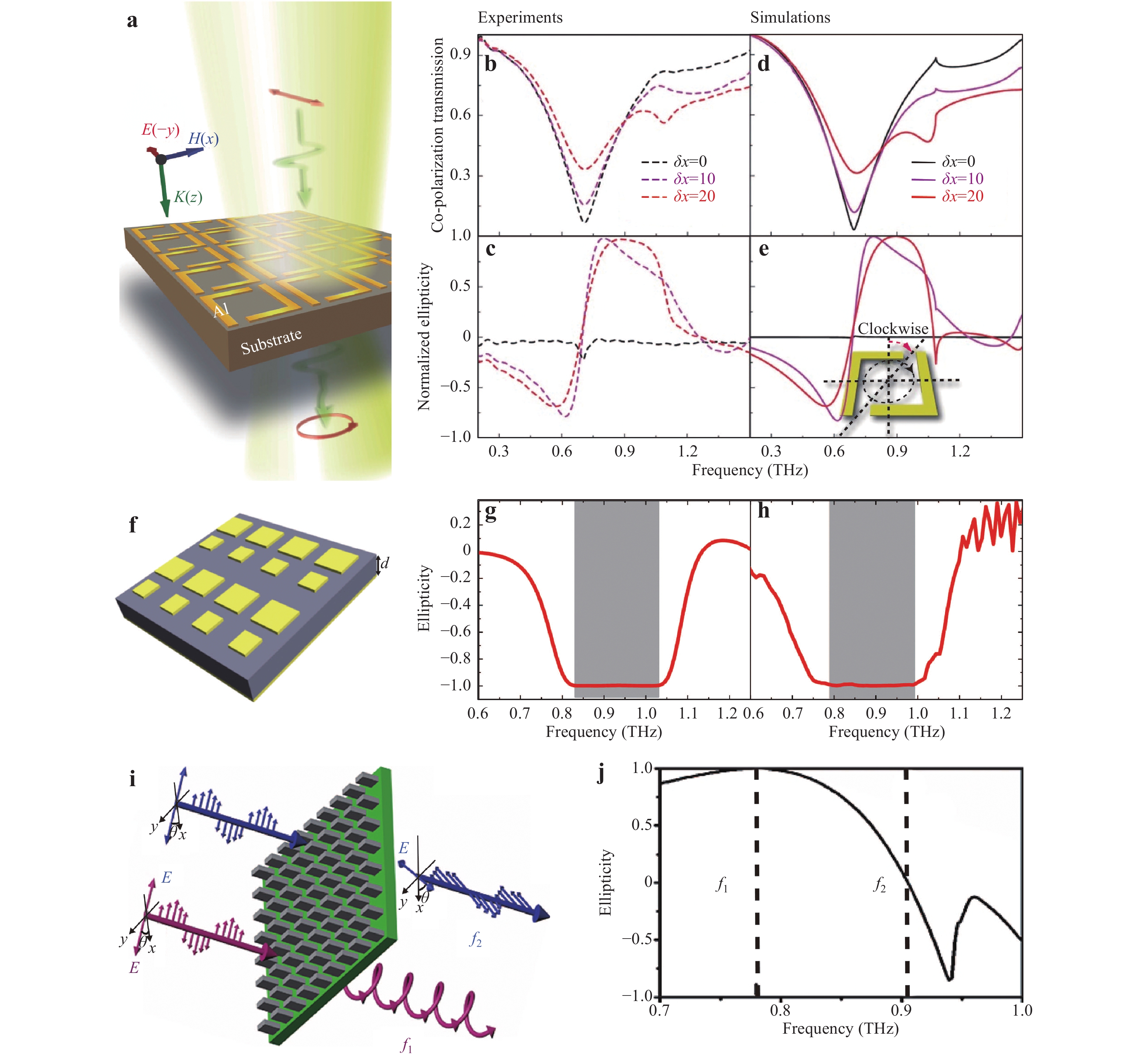
Fig. 10 THz quarter-wave plates.
a Schematic of a linear-to-circular polarisation converter108. b and d Measured and calculated co-polarised transmission spectra108. c and e Measured and calculated ellipticity values for r-SRRs with δx = 0, 10, and 20 μm108. f Schematic of a reflective-type linear-to-circular polarisation convertor111. g and h Calculated and measured ellipticity values111. i Schematic of an all-dielectric metasurface with the functionality of a quarter-wave plate and half-wave plate112. j Simulated ellipticity of the designed polarisation convertor112. Images reprinted with the following permissions: a108, b108, c108, d108, e108 from John Wiley and Sons; f111, g111, h111 from The Optical Society; i112, j112 from AIP Publishing. -
Metasurfaces have the unprecedented capability to manipulate different physical parameters of wavefronts, leading to a variety of unique applications. By accurately controlling angular momentum, amplitude, and phase using ultrathin metasurfaces, special beams such as vortex beams, Bessel beams, and Airy beams can be generated, enabling applications in high-capacity data transmission, super-resolution imaging, particle trapping, etc. In this section, we discuss various metasurface-based devices for generating special beams.
-
EM waves can carry two types of angular momenta: spin angular momentum (SAM) and orbital angular momentum (OAM). SAM is typically associated with CP beams and has only two values of
$ \pm\, \hbar $ (per photon), whereas OAM has various values (e.g.$\ell \hbar $ per photon ($\ell = 0, \pm\, 1, \pm \,2 \cdot \cdot \cdot $ )). Therefore, EM waves possessing OAM, which are defined as vortex beams, can carry unprecedented quantities of data, enabling high-capacity data transmission. Traditional approaches to generating vortex beams include spiral phase plates116, Q-plates117, cylindrical mode convertors118, and spatial light modulators119. Recently, a series of methods were proposed to generate THz vortex beams using metasurface41, 65, based on their ultrathin and broadband characteristics. As shown in Fig. 11a, an ultrathin plasmonic metasurface was proposed to generate THz vortex beams. Eight types of complementary V-shaped slit antennas were designed to encode the helical phase in the metasurface120. Under the illumination of x-polarised THz waves, a converged vortex beam with polarisation along the y-axis can be observed, as shown in Fig. 11b. As illustrated in Fig. 11c, the corresponding topological charge is$\ell = 1$ . For vortex beams, conversion efficiency is one of the most important indicators determining device performance. It was recently reported that the conversion efficiency of vortex beams can be significantly enhanced by all-dielectric metasurfaces consisting of circular or cross-shaped resonators121, 122. By carefully designing dielectric resonators, conversion efficiency can reach as high as 82.5%.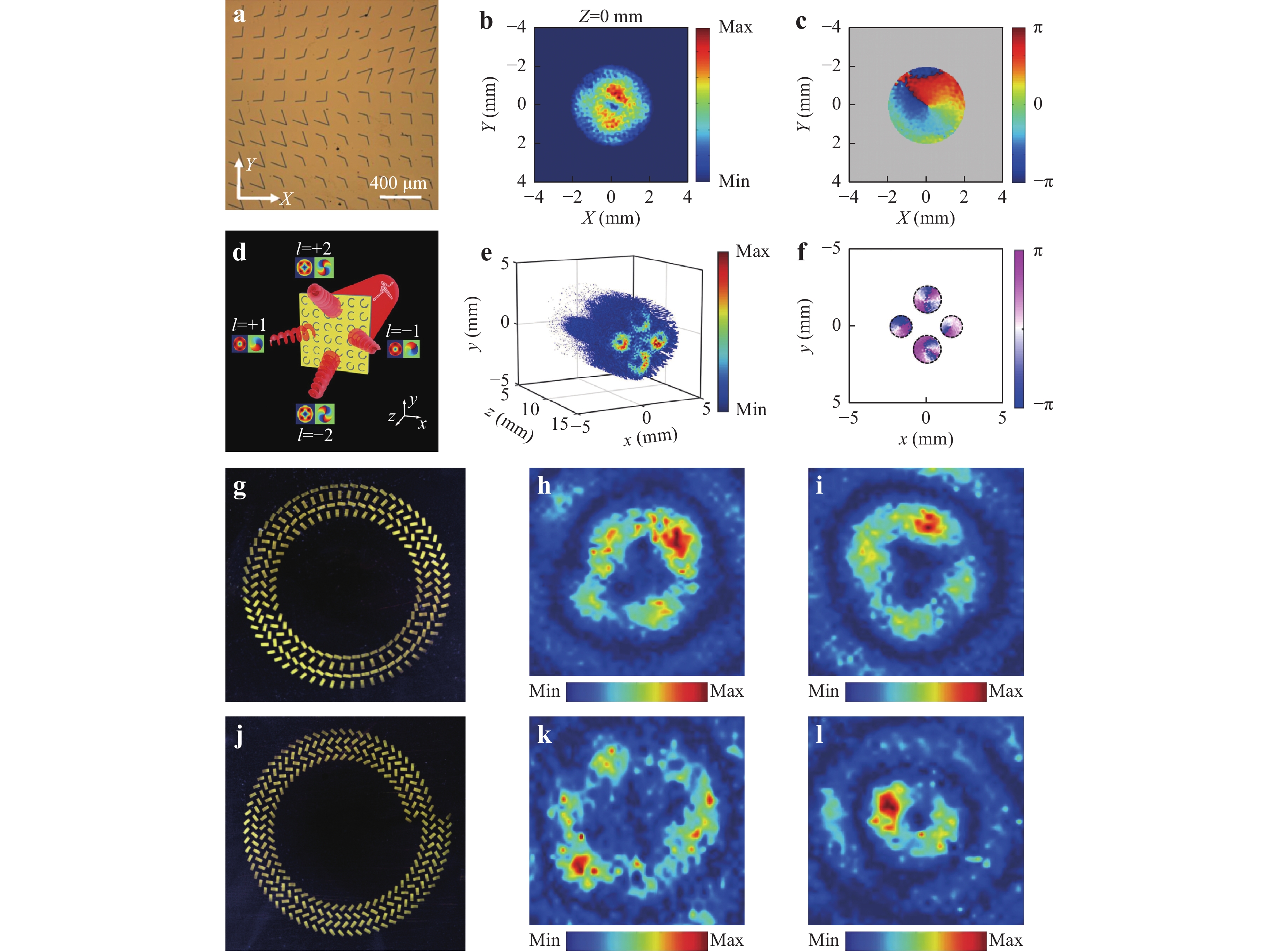
Fig. 11 Metasurfaces for generating vortex beams.
a Optical image of a metasurface for generating a vortex beam120. b and c The intensity and phase distributions of THz vortex beams in the focal plane120. d Schematic of a metasurface for THz OAM multiplexing123. e and f Measured amplitude and phase distributions at predetermined focal plane123. g Metasurface for generating THz OAM beams based on geometric phase124. h and i Measured electric field distribution under the illumination of LCP and RCP THz waves, respectively124. j Metasurface for generating THz OAM beams based on geometric phase and dynamic phase124. k and l Measured electric field distribution under the illumination of LCP and RCP THz waves, respectively124. Images reprinted with the following permissions: a120, b120, c120 from The Optical Society; d123, e123, f123 from ACS; g124, h124, i124, j124, k124, l124 from John Wiley and Sons.However, the aforementioned metasurfaces are restricted to generating only one vortex beam with a specific topological charge. Zhao et al. proposed an approach that can convert LP THz waves into multiple cross-polarised vortex beams with different topological charges, leading to OAM multiplexing123. Fig. 11d presents a schematic of a metasurface for generating multiple converged vortices. Under the incidence of x-polarised THz waves, four converged vortex beams (with polarisation along the y axis) are generated following the designed metasurface, as shown in Fig. 11e. The topological charges of these four vortex beams are ±1 and ±2 respectively (see Fig. 11f). This approach to designing metasurfaces to generate vortex beams in free space (far-field region) can be also extended into the near-field region for converting excited SPPs into plasmonic vortices124, 125. As shown in Fig. 11g, a metal film with annularly distributed air slits was designed to excite helicity-dependent plasmonic vortices based on a pure geometry phase. The topological charges of the plasmonic vortices are determined by the in-plane angle of each air slit. When the rotation angle of the air slits in a turn is 3π, the topological charge is 2 (−2) for the incidence of LCP (RCP) THz waves, yielding two helicity-dependent plasmonic vortices, as shown in Fig. 11h, i. In contrast, when the air slits are designed as Archimedes spiral slit arrays (see Fig. 11j), both helicity-dependent plasmonic vortices are modulated by the geometry phase and dynamic phase. When the rotation angle of the air slits in a turn is also 3π, the topological charge is 3 (−1) under the illumination of LCP (RCP) THz waves (see Fig. 11k, l).
-
Bessel beams exhibit nondiffraction, self-healing, and self-accelerating characteristics. Therefore, they have various applications such as optical tweezing, super-resolution imaging, and molecular detection. Recently, metasurfaces have been proposed to generate Bessel beams based on their flexible wavefront manipulation functionality. Fig. 12a presents a high-efficiency metasurface consisting of tri-layered (C-shaped) resonator arrays for generating Bessel beams50. By encoding a special phase profile onto the matasurface, a Bessel beam with extended focal depth longer than 27λ can be observed, as shown in Fig. 12b. When comparing Fig. 12b, c, one can see that the beamwidth of the main lobe decreases with an increase in the exit angle. By designing an all-dielectric magnetic mirror metasurface (Huygens’ metasurface), Ma et al. experimentally demonstrated a reflection-type Bessel beam with a focal depth of 27λ and conversion efficiency of 80%60. Airy beams with non-diffracting waveforms can also be realised based on metasurfaces via simultaneous amplitude and phase modulation44, 126, 127. Fig. 12d presents a schematic of a metasurface that can simultaneously generate Airy beams for SPPs and transmitted waves. When THz waves are normally incident on the metasurface, the excited SPP Airy beam propagates along the gold/air interface, while the transmitted Airy beam propagates into free space. When the incident THz wave with polarisation switches from LCP to RCP, the position of the SPP Airy beam shifts from the left to the right side of the metasurface, as shown in Fig. 12e, f. Additionally, metasurfaces can generate radially polarised Lorentz beams128. As shown in Fig. 12g, a metasurface composed of cross-shaped resonators with various sizes and orientations has been designed to modulate amplitude and polarisation simultaneously. Under the incidence of LP THz waves, a radially polarised Lorentz beam can be observed following the metasurface, as shown in Fig. 12h, i.
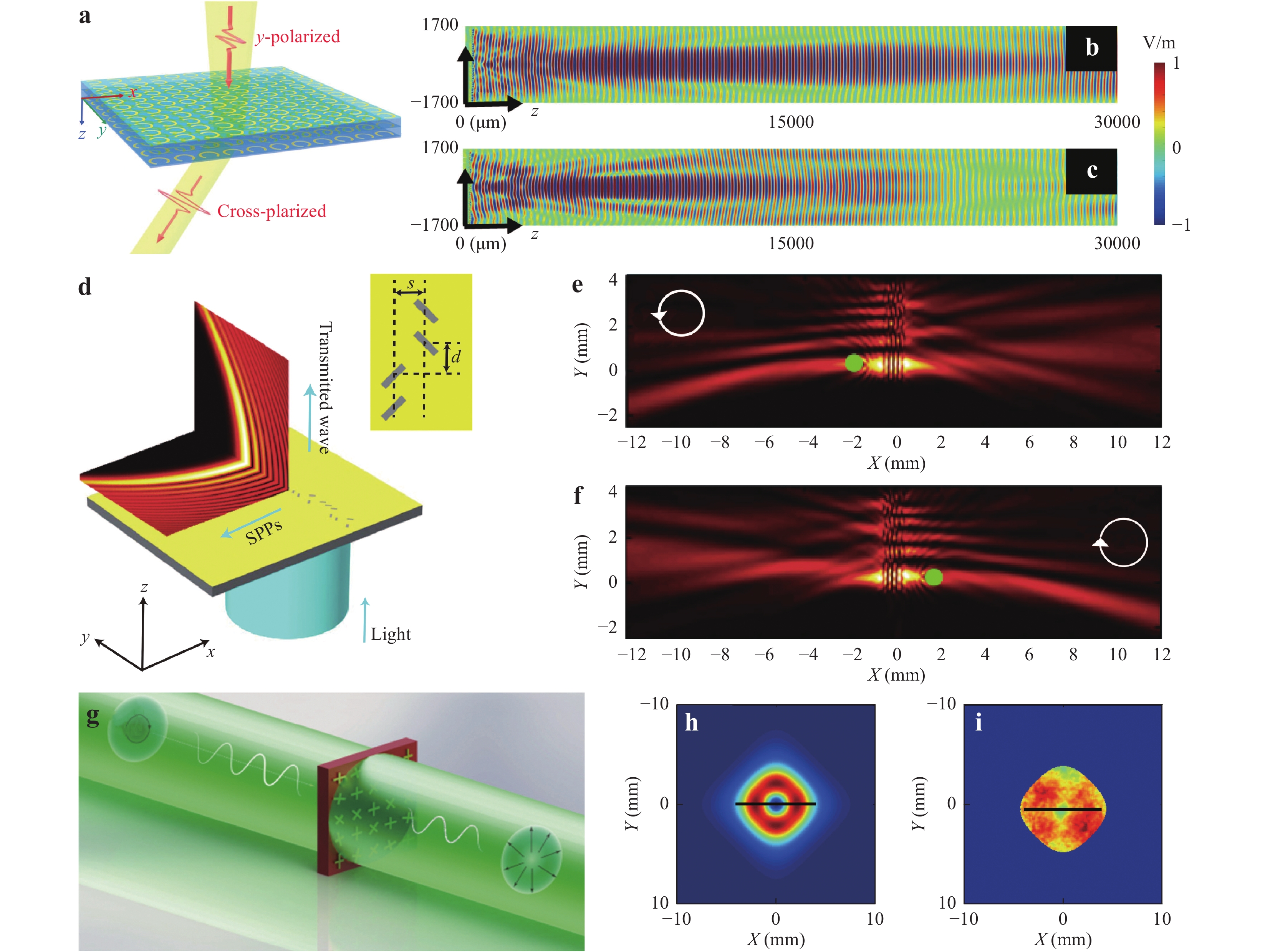
Fig. 12 Metasurfaces for generating Bessel beams, Airy beams, and radially polarised Lorentz beams.
a Schematic of a tri-layered metasurface for generating Bessel beams50. b and c Electric distributions of Bessel beams with different exit angles of 5˚ and 10˚, respectively50. d Schematic of a metasurface for generating Airy beams for SPPs and transmitted waves126. e and f Electric distributions of SPP Airy beams under the illumination of LCP and RCP THz waves, respectively126. g Schematic of a metasurfaces for generating radially polarised Lorentz beams128. h and i Simulated and measured transmission distributions for a radially polarised Lorentz beam128. Images reprinted with the following permissions: a50, b50, c50 from ACS; d126, e126, f126 from The Optical Society; g128, h128, i128 from John Wiley and Sons. -
Although metasurfaces have shown excellent capabilities for manipulating THz waves, their modulation functionalities are still limited based on their fixed structures and material characteristics. Therefore, seeking new approaches to realising active metasurfaces that can dynamically control the wavefronts of THz waves, is of great significant. Active metasurfaces cannot only enable reusable properties, but can also modulate wavefronts to generate predesigned functionalities, meaning active metasurfaces can further expand metasurface applications. In this section, we report recent advancements related to active metasurfaces for the wavefront manipulation of THz waves, including tuneable beam deflectors, metalenses, and holograms.
Graphene, which is a two-dimensional carbon structure, consists of atoms arranged in a honeycomb lattice and typically exhibits gate-controllable light-matter interactions by manipulating Fermi levels. By integrating single-layered graphene onto a patterned metasurface composed of U-shaped apertures (see Fig. 13a), an active metasurface can be formed to manipulate the wavefronts of incident THz waves dynamically129 because the Fermi level of graphene can be accurately controlled by a gate voltage. As illustrated in Fig. 13b, c, the amplitude of anomalous refraction (generated by an active graphene metasurface) can be effectively modulated by controlling the gate voltage. It is also possible to construct active metasurfaces with switchable functionalities in the THz frequencies130–132.
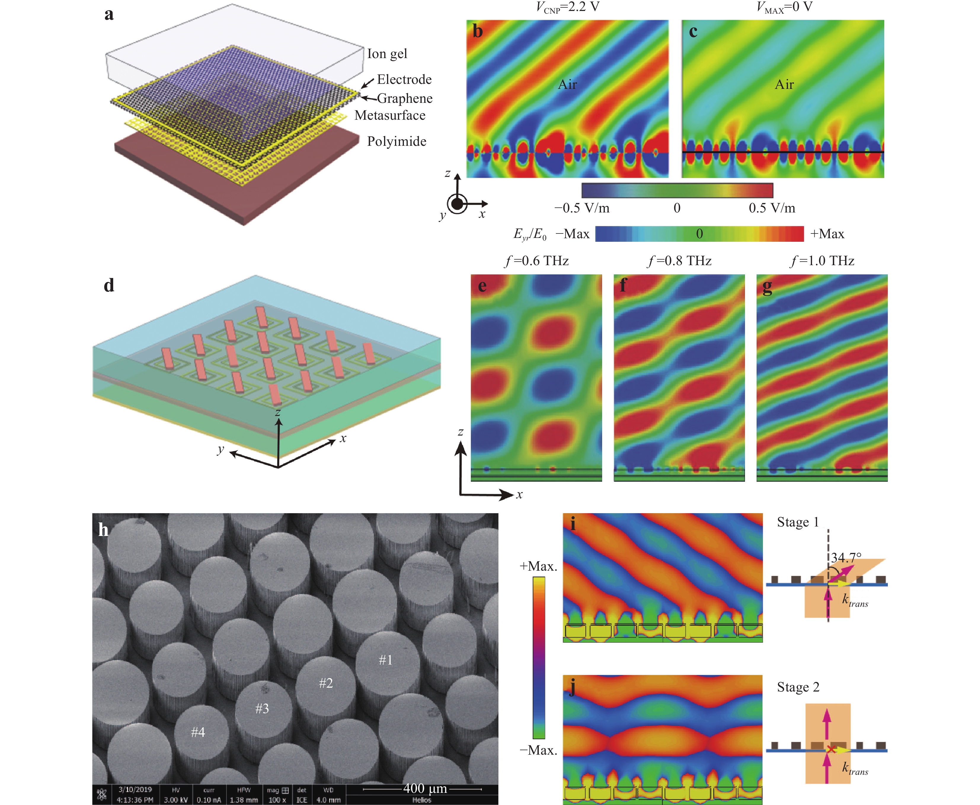
Fig. 13 Active metasurfaces for beam deflection.
a Schematic of an active metasurface consisting of a single layer of graphene deposited on a U-shaped aperture array129. b and c The y component of electric field distributions with gate voltages of 2.2 and 0 V, respectively, under the illumination of LCP THz waves129. d Schematic of an active VO2 metasurface with switchable functionality130. e, f, and g The y components of electric field distributions at 0.6, 0.8, and 1.0 THz, respectively, with σ = 20000 S/m130. h Schematic of a THz tunable beam reflector based on a spatiotemporal dielectric metasurface136. i and j Electric field distributions at two stages based on a temporal modulation136. Images reprinted with the following permissions: a129, b129, c129, d130, e130, f130, g130, h136, i136, j136 from John Wiley and Sons.Fig. 13d presents an active metasurface consisting of periodic VO2 brick-shaped antennas, double SRRs, and VO2 films. By carefully designing the structure of each antenna, a spatially linear phase profile can be obtained to realise THz beam deflection. When x-polarised plane waves are normally incident on the designed metasurface, they are completely absorbed by the VO2 in its insulating state at room temperature (σ = 200 S/m)130. In contrast, 90% of the reflected THz waves are contained within the −1 diffraction order at temperatures above Tc (critical temperature), as shown in Fig. 13e-g. The deflection of THz beams through the VO2 metasurface in both the horizontal and vertical directions can also be realised by the applied current distribution on the VO2 substrate in the horizontal and vertical directions131. Additionally, an all-optical switchable coding metasurface composed of C-shaped metal-VO2 hybrid resonators was proposed to manipulate the wavefronts of THz waves dynamically132. Accordingly, active metasurfaces consisting of C-shaped metal-Si hybrid resonators or C-shaped slit SRRs with Si-GaAs substrates have also been designed to realise THz beam deflectors133, 134. Coherent control of the ratio of deflected THz beams can be realised by controlling the relative phase of two incident beams135. In addition to realising active metasurfaces by controlling the gate voltage and temperature, Cong et al. proposed a spatiotemporal dielectric matasurface (see Fig. 13h) for dynamically steering of THz beam. At temporal 1 (without an external optical field), the transmitted THz wave is steered at an angle of 34.7˚ (see Fig. 13i), while at temporal 2 (with an external optical field), the wavefront (see Fig. 13j) of the transmitted THz wave is directed parallel to the incident THz wave136. This kind of Huygens’ metasurface can be applied to the design THz optically tuneable absorbers that enable an intensity transmission modulation depth of 99.93%137. In addition to external field manipulation, the dynamic control of THz waves can also be realised by mechanically tuneable meatsurfaces138. A cascaded bilayer metasurface has been designed to construct a tuneable beam deflector. When the distance between two metasurfaces ranges 0 to 5176 nm, the deflection angle increases with the displacement of the metasurfaces, leading to a mechanically tuneable THz beam deflector.
Active metasurfaces can be also extended to design dynamic metalenses and metaholography devices. Fig. 14a presents an optical image of C-shaped air slit arrays deposited on a VO2 substrate139. For x-polarised incident THz plane waves, one focal point can be observed following the metasurface at 20˚C (see Fig. 14b), while four focal points are generated at 70˚C (see Fig. 14c). By using a graphene-based metasurface or integrating graphene substrates and resonators/rods, dynamic metalenses can be realised to manipulate the focal lengths of focal points140–143. As shown in Fig. 14d, an active metalens composed of a graphene substrate and anisotropic rods with different orientations has been proposed. When the gate voltage is 0 V, a focal point with a focal length of 10.46 mm is generated, whereas a focal point with a focal length of 12.24 mm is observed for a gate voltage of 2 V, demonstrating a metalens with a tuneable focal length. For a metasurface with C-shaped metal-VO2 hybrid resonators (see Fig. 14g), thermally dependent dynamic holography can be realised144. A letter of ‘H’ can be observed at 25˚C, but it switches to ‘G’ at 100˚C, as shown in Fig. 14h, i, respectively. Additionally, another approach for dynamically generating metasurface structures on a silicon wafer using a spatially modulated femtosecond laser was proposed to generate hologram images dynamically98.
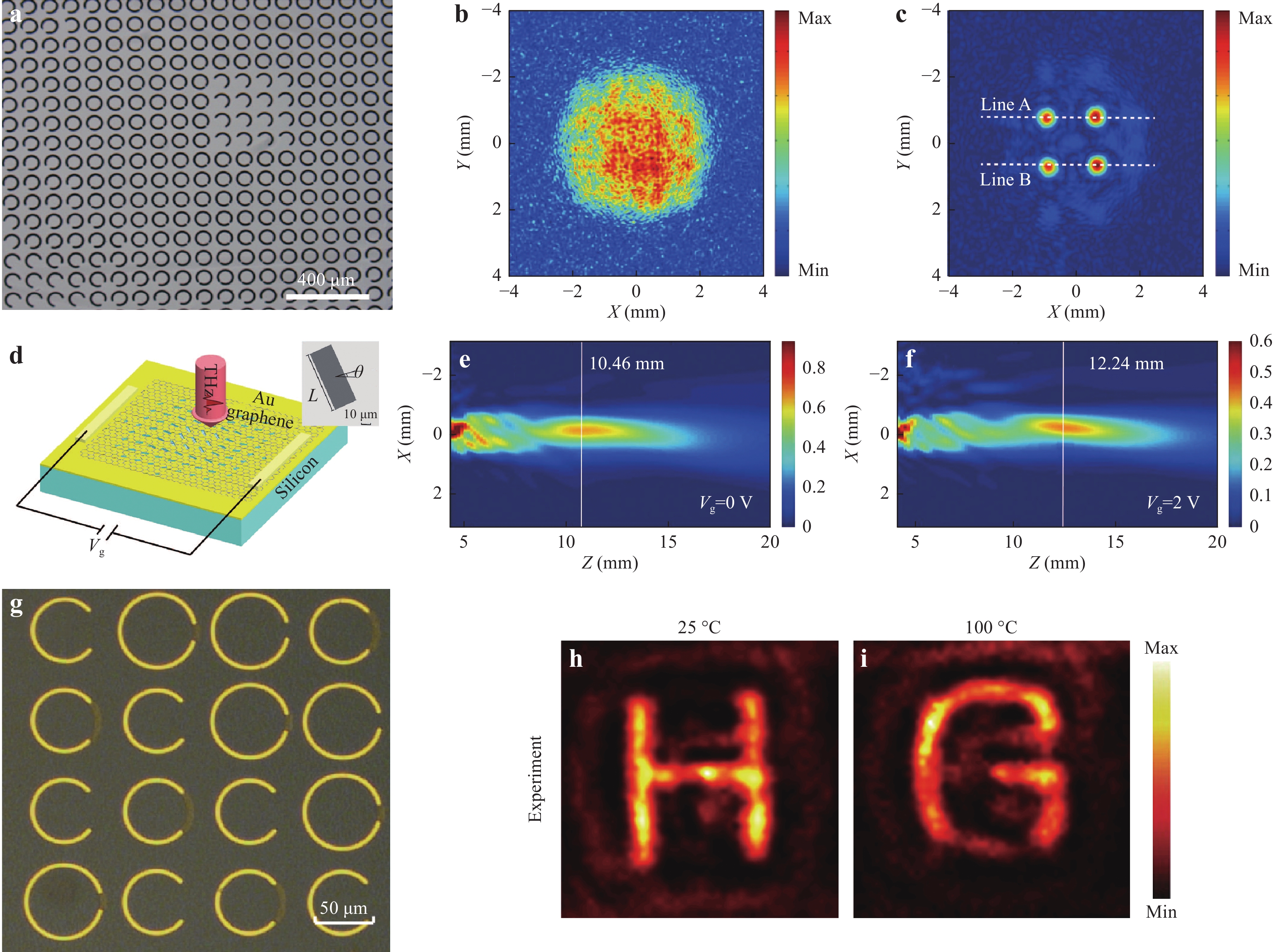
Fig. 14 Active metasurfaces for metalenses and holograms.
a Optical image of active metalens for generating a uniform focal point or four focal points139. b and c The electric field distributions of active metalens at temperatures of 20˚C and 70˚C, respectively139. d Schematic of an active metalens with tunable focal length141. e and f The electric field distributions of the active metalens at gate voltages of 0 V and 2 V, respectively141. g Optical image of metasurface for generating thermally-dependent dynamic meta-holograms144. h and i The electric field distributions of the active metalens at temperatures of 25˚ and 100˚, respectively144. Images reprinted with the following permissions: a139, b139, c139 from The Optical Society; d141, e141, f141 from Chinese Laser Press; g144, h144, i144 from John Wiley and Sons. -
Amplitude, polarisation, and phase are the fundamental properties of THz waves, whose spatial distributions can be applied to process, store, and record information. Therefore, the manipulation of THz wavefronts is of great significance. Traditional elements for manipulating THz waves, such as lenses, wave plates, attenuators, and reflectors, are hindered by their large and bulky volumes, limiting their applications and the development of next-generation on-chip devices. Although metamaterials have achieved remarkable results based on the tuneable electric permittivity and magnetic permeability of meta-atoms, they are limited by technical challenges in their fabrication and the high loss of metal-based unit cells. Metasurfaces with planar structures can locally modify the wavefronts of THz waves at subwavelength resolutions. Metasurfaces not only provide an ultra-compact platform for manipulating the wavefronts of THz waves, but can also facilitate a plethora of applications that are difficult to realise using conventional functional devices. An overview of recent developments related to metasurfaces for manipulating THz waves was presented in this paper. The fundamental principles of metasurfaces for controlling LP/CP EM waves were introduced. Ultrathin THz metalenses, including the spin-dependent metalens, spin-insensitive metalens, polarisation-controllable metalens, and achromatic metalens, were discussed. Metalenses for THz imaging have been developed and experimentally demonstrated in several studies. THz holograms based on metasurfaces have been achieved by flexibly designing the structure sizes and/or orientations of each SRR or rod. Various applications of metasurfaces for generating ultrathin THz waveplates (e.g., half-wave plates and quarter-wave plates) and special beams (e.g., THz vortex beams, THz radially polarised beams, and THz Bessel/Airy beams) have also been realised. Additionally, active metasurfaces have been proposed to manipulate THz waves dynamically.
Metasurface-based approaches to manipulating THz waves have made significant contributions to the development of ultrathin/ultra-compact and tuneable THz components. The main advantages/contributions of THz metasurfaces can be summarised as follows. (1) THz components have reduced size. The functionalities of focusing, OAM, and polarisation conversion realised by metasurfaces have traditionally been obtained by using a THz lens, helical phase plate, and half-wave (or quarter-wave) plate, respectively. However, these traditional THz components are relatively thick and require specific surface topographies to realise the desired wavefront manipulation (or predesigned functionality). The typical thicknesses of these traditional THz components are on the order of centimetres, leading to large and bulky THz devices. Metasurfaces typically consist of planar meta-atoms that provide a flexible platform for designing ultrathin/ultra-compact THz components based on abrupt phase changes in EM waves at meta-atom interfaces. For example, the thicknesses of metal-based metasurfaces for metalenses, OAM generators, and linear-to-circular polarisation converters72, 111, 124 are 6.2, 25.2, 25.2 μm, respectively, meaning these devices are much thinner than traditional THz components. The thickness of an all-dielectric metasurface-based THz component (e.g., THz metalens87) is typically on the order of millimetres. THz components realised using metasurfaces provide reduced thickness, leading to significant advantages in terms of designing ultrathin/ultra-compact THz components. (2) Metasurface-based THz components can provide multiple functions. Traditional THz devices (e.g., THz lenses and waveplates) can only provide a single function. Metasurfaces not only provide a flexible platform to realise ultrathin/ultra-compact THz devices with single functions, but also provide unprecedented capabilities for designing multifunctional THz devices. A THz lens combined with a THz half-wave plate can focus and rotate the polarisation of incident THz waves into a focal point, but the focusing phase and polarisation-rotation phase can be simultaneously encoded onto a single metasurface, yielding a multi-foci metalens with polarisation-rotated focal points89. A polarisation-rotation phase and beam-splitting phase can also be encoded onto a single metasurface to realise multi-channel THz polarisation rotators104. Conventional imaging systems for realising achromatic functionality use multi-lens cascades to compensate for phase differences, whereas a single metasurface (e.g., achromatic metalens) can enable both focusing and dispersion compensation functionalities83. Additionally, polarisation-dependent phase modulations can be encoded onto a single metasurface for generating polarisation-dependent holograms94 that are difficult or impossible to achieve using conventional methods. (3) Metasurface-based THz components provide tuneable functionality. Traditional THz components provide fixed functionality based on their fixed structures and material characteristics. Metasurfaces combined with VO2, graphene, etc. can open new avenues for developing THz components with active functions. For example, by modulating the gate voltage, a patterned metasurface composed of U-shaped apertures combined with single-layer graphene can effectively modulate the amplitude of anomalous refraction129. A metalens with a tuneable focal length can be realised by integrating a graphene substrate with metasurfaces141. Additionally, thermally dependent dynamic metaholograms can also be realised by combining metasurfaces with VO2144. Although metasurfaces have exhibit many promising features, there are still some challenges must be addressed. We propose some promising future directions for THz metasurface research below.
Most metasurface-based THz functional devices utilise passive metasurfaces that are limited to fixed functions. Creating a single metasurface-based THz device with tuneable properties or switching functionality is a difficult task. Although approaches such as thermal tuning, geometrical deformation, and voltage bias have been introduced into metasurfaces to generate tuneable functionalities, these methods are limited by requirements for special materials such as semiconductors145, graphene140–143, 146, 147, VO2130-132, 139, 144, and Ge2Sb2Te5148. Therefore, tuneable functionalities are limited to global manipulation, rather than the independent modulation of individual meta-atoms. Therefore, metasurfaces with tuneable functionalities for individual meta-atom/unit cells are very important. Recently, Cui et al. proposed a coding scheme for designing digital and programmable metasurfaces that can facilitate the digitalised description of metasurfaces to provide flexible and real-time manipulation of EM waves in the spatial domain, frequency domain, and space-frequency domain149–155. By integrating biased diodes into a metasurface, one can digitally modify the voltage distributions on the metasurface by using field-programmable gate array hardware to control the ‘ON’ and ‘OFF’ states of the biased diodes, leading to to the required ‘0’ and ‘1’ states for a programable metasurface. If this approach is extended into the THz region, we believe that it will yield a series of practical applications in THz communications, imaging, and detection.
THz metalenses, which represent a prominent application of metasurfaces, have shown unprecedented functionality compared to traditional lenses. As a typical application, THz metalenses can be used for imaging. However, imaging resolution is limited by the diffraction limit. Although a plasmonic metalens has been proposed and fabricated84, this type of metalens is limited to near-field imaging with a tight focus and low focusing efficiency. Therefore, the development of metalenses with high focusing efficiency and far-field superfocusing is desirable. One could integrate polarisation modulation to obtain radially polarised beams with phase modulation to focus radially polarised beams into an all-dielectric metasurface to achieve a high-performance longitudinally polarised focal point156 that can be applied to high-resolution medical imaging157 and defect detection158. Additionally, previously reported THz metalenses are symmetric in the forward and backward directions. It is necessary to develop directional metalenses with asymmetric focusing159 that can be used for unidirectional imaging. Directional metalenses would provide the functionality for capturing information one side while protecting information on the other side, meaning they could be utilised for information security and cloaking applications.
THz components with multiple functions are promising for device miniaturisation. Although the multiplexing of multiple functions into a single metasurface provides significant advantages, crosstalk between different functions is an issue that must be addressed. For example, Zhou et al. proposed a spin-decoupled metalens to generate helicity-dependent vortices independently. Crosstalk is generated when multiple helicity-dependent vortices are generated for incident LP THz waves160. Crosstalk in the multiplexing of plasmonic vortices has also been observed161. With an increase in the number of functions encoded on a single metasurface, crosstalk will become more apparent. One could adopt optimisation algorithms such as the particle swarm algorithm162 and covariance matrix adaptation evolutionary strategy33 to eliminate crosstalk. Another intriguing research direction is artificial-intelligence-enhanced photonic techniques (e.g., photonics neural networks). We believe that multi-functional metasurface-based THz components will be made much more efficient and performant with the aid of machine learning techniques163, 164.
In addition to device miniaturisation, system integration is an important topic driving the development of advanced THz technology. THz metasystems that can integrate a variety of metasurface-based devices for manipulating THz waves represent a promising research topic in this field. One promising direction is the design of metasystems consisting of two or more cascaded metasurface devices for realising more complicated functionality. Another intriguing direction is to integrate metasurface devices into conventional THz components that can simultaneously leverage the advantages of each type of component165, 166. Based on their ultrathin and ultra-compact characteristics, as well as their flexible wavefront-manipulating functionality, metasurfaces will inevitably promote the development of THz science and technology.
-
This work is supported in part by the National Key Research and Development Program of China (2017YFA0701005), National Natural Science Foundation of China (61871268, 61722111), Natural Science Foundation of Shanghai (18ZR1425600), Shanghai Pujiang Program (18PJD033), "Shuguang" Program of Shanghai Education Commission (19SG44), Shanghai international joint laboratory project (17590750300), 111 Project (D18014), and Shanghai top talent program. the Russian Foundation for Basic Research under Grant 18-29-20104 and Grant 20-21-00143, the Ministry of Science and Higher Education in part within the Agreement No. 075-15-2019-1950, in part within the State assignment FSRC “Crystallography and Photonics” RAS.
Metasurfaces for manipulating terahertz waves
- Light: Advanced Manufacturing 2, Article number: (2021)
- Received: 04 August 2020
- Revised: 11 November 2020
- Accepted: 26 February 2021 Published online: 22 March 2021
doi: https://doi.org/10.37188/lam.2021.010
Abstract: Terahertz (THz) science and technology have attracted significant attention based on their unique applications in non-destructive imaging, communications, spectroscopic detection, and sensing. However, traditional THz devices must be sufficiently thick to realise the desired wave-manipulating functions, which has hindered the development of THz integrated systems and applications. Metasurfaces, which are two-dimensional metamaterials consisting of predesigned meta-atoms, can accurately tailor the amplitudes, phases, and polarisations of electromagnetic waves at subwavelength resolutions, meaning they can provide a flexible platform for designing ultra-compact and high-performance THz components. This review focuses on recent advancements in metasurfaces for the wavefront manipulation of THz waves, including the planar metalens, holograms, arbitrary polarisation control, special beam generation, and active metasurface devices. Such ultra-compact devices with unique functionality make metasurface devices very attractive for applications such as imaging, encryption, information modulation, and THz communications. This progress report aims to highlight some novel approaches for designing ultra-compact THz devices and broaden the applications of metasurfaces in THz science.
Research Summary
Metasurfaces: A new platform for designing ultrathin THz devices
Traditional THz functional devices are bulky and must be sufficiently thick to generate propagation phase accumulation to realize the desired wave-manipulating functionality. Metasurfaces, which are two-dimensional metamaterials consisting of predesigned meta-atoms, can accurately tailor the amplitudes, phases, and polarisations of electromagnetic waves at subwavelength resolutions, meaning they can provide a flexible platform for designing ultra-compact and high-performance THz components. Xiaofei Zang et al. from China’s University of Shanghai for Science and Technology now report recent advancements in metasurfaces for the wavefront manipulation of THz waves based on these ultrathin and ultra-compact devices. The team aim to highlight some novel approaches for designing ultra-compact THz devices and broaden the applications of metasurfaces in THz science and technology.
Rights and permissions
Open Access This article is licensed under a Creative Commons Attribution 4.0 International License, which permits use, sharing, adaptation, distribution and reproduction in any medium or format, as long as you give appropriate credit to the original author(s) and the source, provide a link to the Creative Commons license, and indicate if changes were made. The images or other third party material in this article are included in the article′s Creative Commons license, unless indicated otherwise in a credit line to the material. If material is not included in the article′s Creative Commons license and your intended use is not permitted by statutory regulation or exceeds the permitted use, you will need to obtain permission directly from the copyright holder. To view a copy of this license, visit http://creativecommons.org/licenses/by/4.0/.






 DownLoad: