


-
The hologram of an object or a scene consists of the recording of the interference between two mutually coherent waves, arising from a laser beam split into two parts, the first travelling via the object (the object beam) and the second one not (reference beam). At the early stage of holography, holograms were recorded on photochemical recording materials1 (nowadays called “analogue holography”), which are still of great interest for the 3D rendering of portraits or scenes2. Soon in the mid-'60s, holographic interferometry (HI) surfaced. It uses the interference of two or more wavefronts read out through holograms recorded at different states of a moving object, yielding observation of interference patterns (interferograms) after the holographic plate3. These patterns can be related to phase change in the object or scene. HI was applied since then in an ever-increasing number of applications, among which fluid mechanics, solid mechanics, nondestructive testing (NDT, e.g. damage/crack detection), among others4, 5. The rapid need for industrial applicability of HI devices led to the introduction of simplified hologram recording modalities6. Mainly, electronic recording devices were used to store holograms directly on the matrix sensor, owing to the speckle effect (in which case holograms are called specklegrams). The speckle pattern interferometry can be used to retrieve an interference pattern similar to HI for monitoring object changes7, 8. Later digital holography (DH) was proposed also based on electronic recording9. Contrarily to speckle interferometry, which requires a lens to image the subjective speckle on a matrix sensor, DH can be used under a wide variety of optical schemes10. In particular, lensless schemes are possible. The object wavefront is then calculated using free space propagation integral on the digitally recorded hologram pattern up to the object location by numerical refocusing. One popular configuration is the off-axis DH using the Fresnel approach under paraxial approximation, applying simply fast Fourier transforms (FFT)11. The other one is inline DH with phase-shifting (PS), which allows eliminating unwanted diffraction orders superposed to the object image12.
Whether one considers analogue holography, speckle interferometry or DH, the laser wavelength
$ \lambda $ plays a central role. Soon at the beginning, its impact on setup stability requirements, HI measurement range and the type of object’s reflectivity were experienced.Most of the holography applications are performed at visible wavelengths. This is due to the fact that many components are readily available in visible (lasers, cameras, recording materials, optical components), but also simply because many applications are intended to display images for the human eye. Despite this, applying holography at non-visible wavelengths can provide fascinating outcomes.
In this paper, we will present developments and results obtained by several groups with DH and speckle interferometry at long wavelengths. Mainly, we will concentrate on long-wave infrared (LWIR) and beyond, the Terahertz (THz) waves. Shorter IR wavelengths (SWIR and MWIR) are not considered here, mainly because long coherence length lasers are still difficult to find with sufficient power and affordable prices. To clarify the ideas, we consider LWIR extending from 7 µm to 15 µm. Then comes the far-infrared (FIR), starting at 15 µm (20 THz frequency) and generally considered as the start of the THz spectrum. The sub-THz range extends from 300 µm to 3 mm (1 to 0.1 THz). Also, although some analogue recording materials were demonstrated in the past (reviewed elsewhere13, 14), they proved to be unpractical. Therefore, we will focus on digital hologram recording.
After briefly reviewing the main components necessary in these ranges, we will see that long wavelengths can solve some issues experienced in the visible. Meantime, other issues will appear as well as interesting features that can be used advantageously. The paper is not intended to be an exhaustive review. Instead, we will emphasize the limits of using long wavelengths while showing their benefits through some representative applications in both the LWIR and the THz.
-
In holography, the main components needed are lasers, camera matrix sensors, beamsplitters and combiners, and a series of more classical components for beamforming. Exhaustive reviews of existing technologies were given elsewhere: for the LWIR, see Georges13, and for THz, see, for instance, Valzania et al. 15. Here we give only a short introduction for understanding the rest of the paper. Regarding sources, since we need good coherence lengths, we limit the discussion to continuous ones.
In LWIR, the main source of interest is the CO2 laser, emitting lines around 10µm, powerful (a few watts), relatively stable and with hundred meters coherence lengths13. This source is the one used the most in LWIR, although quantum cascade lasers (QCL) are also studied for holography16.
Concerning cameras, two leading technologies exist. The cooled cameras are developed with either the quantum-well infrared photodetectors (QWIP) or the Mercury Cadmium Telluride (MCT), the latter being the most available commercially. They can be found in large formats and show very low noise, but their cooling system generates vibrations, which we found incompatible with a proper holographic recording. Therefore, uncooled technologies will be preferred. In these, we find the pyroelectric and the microbolometer technologies. The former was used for the very first demonstration of LWIR DH17 but had limited pixel numbers. Microbolometer cameras are now well established in the thermography market. While having lower signal quality than cooled cameras, they have ever-increasing pixel numbers (up to megapixel format) and were used in most applications discussed in the paper.
In THz-FIR, the widespread coherent sources are the gas lasers, with up to 500 mW power at 118.8 µm (295-FIR laser by Edinburgh Instruments). It is composed of a 200W CO2 laser, pumping a cell filled with various gases in order to obtain different wavelengths, between 90 µm to 500 µm. QCL lasers make rapid progress towards similar powers. In the sub-THz range, impact ionization avalanche transit-time (IMPATT) diodes and Gunn diodes are compact sources in this category15. These sources are highly coherent. Therefore, the coherence length is not an issue for interferometry with the object at meter distances.
THz cameras are primarily based on microbolometer technologies adapted to the THz range. Interestingly, microbolometers can be used at FIR wavelengths because of some residual response, although only under the lensless scheme (without LWIR imaging lens)18.
Other optical components (lenses, mirrors, beamsplitters, etc.) can be found easily on catalogues by various manufacturers. The reader should refer to previous reviews papers for more details13, 15.
-
The interference fringes in front of the detector plane are continuous and infinite. However, during the digital hologram recording, they are sampled by the camera with discrete pixels and a finite extent of the imaging area. Visible, LWIR and THz cameras typically have µm-scale pixel pitch
$ p $ and tens of mm-scale imaging area$ Np\times Np $ ($ N $ number of pixels), whereas the working wavelengths differ by 2-3 orders of magnitude. Naturally, the optimum recording conditions to be respected for faithful hologram recording vary. We now discuss these concerns and their impacts based on the three typical cases summarized in Table 1.λ (μm) p (μm) N θmax (deg) zmin* (m) Intrinsic resolution dr Visible 0.532 4 1000 × 1000 3.8 15 0.0001 z LWIR 10.6 17 640 × 480 18 3.2 0.001 z THz 118.8 17 640 × 480 − − 0.01 z *For a 2 m object Table 1. Typical parameters of cameras and impact of wavelength on distance object-detector and resolution
The first aspect is that the spatial sampling condition should be fulfilled: the finest fringe should be correctly sampled by the pixels, which limits a maximum off-axis angle14:
$$ {\theta }_{max}=2{\mathrm{sin}}^{-1}\left(\frac{\lambda }{4p}\right) $$ (1) This implies that, when observing an object with lateral dimension
$ D $ , a minimum recording distance should be respected, following$$ {z}_{min}\approx \frac{2p\left(D+Np\right)}{\lambda } $$ (2) For a given recording distance, larger objects can be observed when working with a longer wavelength. The maximum off-axis angle at visible (
$ \lambda $ = 532 nm) with a typical pitch p = 4 μm is 3.8 degrees. A 2m-sized object should be set at least 15 m away from the camera. The maximum off-axis angle at LWIR ($ \lambda $ = 10.6 µm) with pitch p = 17 μm is relaxed to 18 degrees. The minimum recording distance is reduced to 3.2 m. At THz range, especially when working with typical bolometer cameras, the off-axis angle is no longer limited since$ \lambda > 4p $ hold in many cases. The relaxation of maximum off-axis angle is advantageous for situations where a large field of view is expected. Coincidentally, at the LWIR range, the high output power of CO2 lasers guarantees sufficient flux for illuminating large areas. On the other hand, although the sampling condition is no longer an issue for THz DH, macroscopic objects imaging is unsuitable due to the lack of powerful THz sources. Thus, LWIR DH is the best choice for large object or scenes imaging, as is demonstrated by Ferraro’s group in a series of papers19-23. They noticed that, at such wavelengths and with setup parameters discussed above, the speckle grains become very large and affect the reconstructed image quality. Nevertheless, special techniques described elsewhere can mitigate this24.The second concern is the size of the imager area. The intrinsic resolution is diffraction-limited, i.e., the lateral resolution depends on the wavelength and the numerical aperture (NA) of the imaging system. Under lensless DH configuration, the NA is determined by the size of imager
$ Np $ and the recording distance between the object plane and the detector plane:$$ {d}_{r}=\frac{\lambda }{2NA}=\frac{\lambda }{2\mathrm{sin}\alpha }=\frac{\lambda }{2}\sqrt{{\left(\frac{2z}{Np}\right)}^{2}+1}\approx \frac{\lambda z}{Np} $$ (3) The high-frequency components of object wave are diffracted outside of the imager zone. Therefore, they are lost during DH recording. As a result, the attainable intrinsic resolution decreases proportionally with working wavelength. LWIR DH with a slightly lower lateral resolution is acceptable for macroscopic DH applications. However, the diffraction is severe when using THz wavelength. Achieving a sub-mm level resolution regarded as a minimum requirement in most THz imaging cases remains challenging due to the large wavelength. Thus minimizing the object-detector distance is crucial for THz imaging. The recording distance is often squeezed to less than 5 cm when working with the 1cm2-sized imagers at THz wavelength. The geometrical configuration often sets the lower limit of object-detector distance.
For THz off-axis DH setup, one should leave enough space for reference wave injection: the object-detector distance can be reduced to 1 cm. For inline DH or other reference-free phase retrieval setup, the recording distance can be reduced further. An extensive detection area is needed for Sub-THz DH due to the mm-level wavelength. Suitable 2D array detectors are not yet available. Therefore Sub-THz DH is realized by a raster-scanned detector. For instance, in Heimbeck et al.25, when working at 0.495 THz (λ = 606 µm), for a sample located 16.3 cm away from the detector, a detection area of
$ 20\;\times\; 20 $ cm2 is needed to achieve a lateral resolution comparable to the wavelength. The short recording distance in THz DH translates to a high Fresnel number. Therefore, the angular spectrum method (ASM)10 and Rayleigh-Sommerfeld convolution10 are more suitable than the paraxial Fresnel approximation for THz DH reconstruction. Consequently, the discrete Fresnel transform method, which is widely used in visible and LWIR DH for its simplicity (only one FFT is required) and the flexibility of reconstructing large FOV, is not appropriate for THz DH. -
HI is used for measuring variations of the phase
$ \varphi =2\pi nl/\lambda $ of the objects by subtracting the phase from holograms recorded at different object states. Phase variations$ \mathrm{\Delta }\varphi $ can occur through any change related to the object wave, i.e. in the optical path length (the product of the refractive index$ n $ and the geometrical path length$ l $ ) or the wavelength$ \lambda $ . Regardless of the nature of phase change, an interference pattern (interferogram) is observed in the image plane$ (x,y) $ . It is expressed as$$ I\left(x,y\right)={I}_{0}(x,y)\left[1+m\left(x,y\right)\mathrm{cos}\left(\mathrm{\Delta }\varphi \right(x,y\left)\right)\right] $$ (4) with
$ {I}_{0} $ the average irradiance and$ m $ the contrast. The goal is to retrieve the phase change and to interpret the optical path difference (OPD) which induces the phase change. In DH, the phase is easily obtained in the reconstruction process, while in some other versions of holography (analogue holography, speckle interferometry), phase quantification techniques must be considered5,6,26. In any case, once the phase difference$ \mathrm{\Delta }\varphi $ is computed, it can be related to the OPD and the wavelength through$ \mathrm{\Delta }\varphi =\left(2\pi /\lambda \right)OPD $ .In transmission mode, the light passes through the transparent object. The OPD between two points relates to the variation of thickness
$ \Delta t $ or refractive index$ \Delta n $ . For a homogeneous transparent object with refractive index n, the thickness difference between two points is written as$ \Delta t= \Delta \varphi \lambda /\left[2\pi \right(n-1\left)\right] $ . For an object with uniform thickness$ t $ , the refractive index variation is$ \Delta n= \Delta \varphi \lambda /\left[2\pi \right(t-1\left)\right] $ .Under reflection configuration, the light is reflected by the surface of the object under investigation. The phase difference reveals the object’s 3D profile. The phase difference is proportional to the height variation
$ \Delta d $ of the surface profile.The measurable range and resolution are two aspects that should be noticed when relating the phase distribution and the measurand. First off, the obtained phase distribution is wrapped in modulo 2π. A more extensive measurement range of variation corresponds to 2π phase variation thanks to the large working wavelength. As illustrated in Fig. 1, a deformation ranging from 0 to 50 µm is observed using reflection configuration under normal incidence illumination. In this case, the relationship between the deformation
$ \Delta d $ and the phase map$ \mathrm{\Delta }\varphi $ obeys the following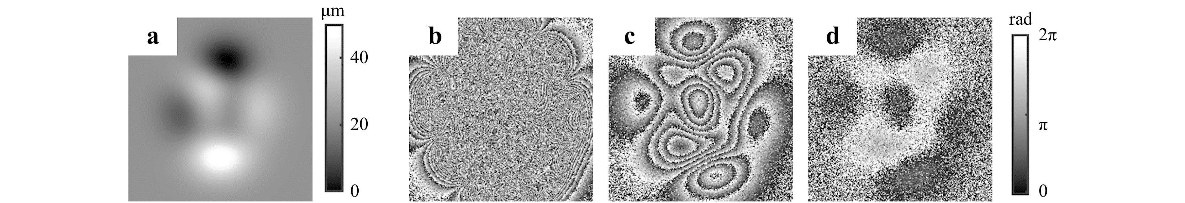
Fig. 1 Simulation of phase variation under different working wavelengths. a shows the simulated deformation map. b−d shows the wrapped phase obtained at resp. 532 nm, 10.6 µm, 118.8 µm based on Eq. 5.
$$ \mathrm{\Delta }\varphi =\left(4\pi /\lambda \right)\Delta d $$ (5) Since the phase retrieved is always obtained modulo
$ 2\pi $ , there the deformation is too large to be observed in visible wavelength (Fig.1b) because the resolution criteria of Nyquist-Shannon is not fulfilled to distinguish two neighbouring fringes. The number of fringes reduces with the increase of working wavelength. However, the measurement precision decreases when working with a large wavelength since the measurand is proportional to the wavelength. It is considered as a shortcoming when working with THz wavelength. In the same example, if the phase resolution, i.e., the minimum distinguishable phase variation, is 0.2 rad for three wavelengths, the minimum measurable displacement will be λ/63, which corresponds to 0.17 µm in Fig. 1c whereas 1.9 µm in Fig. 1d. If prior knowledge of the deformation is known, unwrapping the phase obtained with LWIR in Fig. 1c will give the optimum result among the three wavelengths. -
The fact that an object appears scattering or specular depends on the ratio between its roughness
$ R $ and$ \lambda $ 27. If$ R\ll \lambda $ , the object appears purely specular, while for$ R\gg \lambda $ , it appears purely scattering, favoring the speckle effect. In practice, things are not so simple; some surfaces may appear partly scattering and specular when the roughness is close to$ \lambda $ .In the case of solid reflecting objects, holography is easily applicable when the surface appears scattering. The object reflects part of the light to the camera, where it interferes with the reference beam. As long as a good balance of power between reference and object beams is guaranteed, there is always a way to maximize the hologram contrast at recording. This allows the development of lensless DH configurations, where imaging lenses are not necessary for image focusing. When the object is specular, this is more complicated to achieve because the light reflected by the object can fall well out of the hologram recording location. The light collection is necessary through schemes adapted explicitly to the object shape. This is feasible in a very limited number of cases (both spherical and aspheric optics cases), but complex specular surface shapes could be too challenging. Artificially introducing a scattering property is feasible: removable powder is often applied on objects. However, this is not always feasible or recommended in actual industrial applications.
Working at long
$ \lambda $ further complicates the problem since surfaces scattering in visible become specular in LWIR. Even some objects present neighbouring surfaces with either specular or scattering behaviour. Therefore this reflectivity issue has to be considered in developing a LWIR interferometer and strongly depends on the targeted objects.One application discussed later concerns the NDT of carbon fibre-based composite structures. We found that many composites have a roughness of the order or more significant than the wavelength of CO2 laser28. Therefore, the object is sufficiently scattering to allow DH or speckle interferometry. On that basis, we were able to use a mobile LWIR speckle interferometer on aeronautical parts29.
In another application, the target objects are large aspheric reflectors for space that are purely specular. The removable powder cannot be applied. In some specific cases (concave or flat surfaces), such mirrors can be illuminated by an extended diffuser which generates artificial scattering reflected by the mirror towards the camera sensor, enabling hologram recording. This was studied in detail elsewhere30 and will be presented in section applications.
Sometimes objects have neighbouring areas with either specular or scattering behaviour. This requires specific illumination arrangements for dealing with both at the same time31.
-
Recording holograms with larger wavelengths makes the setup more tolerant to external perturbations. Setup stability is a non-trivial requirement for interferometric technologies, including digital holography. Any perturbation in the environment can lead to the variation of the phase of beams reaching the detector (mainly the one from the object), blurring the interference fringes. As a rule of thumb, the optical path in the interferometric setup should vary no more than a fraction of the laser wavelength during hologram recording. For that reason, holography at visible wavelengths requires setup to be mounted on vibration-isolated tables and preferably with tabletops to avoid air turbulence or alternatively making use of short laser pulses.
In some cases, working out-of-the lab is necessary and using long-wavelength alleviates the stability requirement for DH setup. This feature makes LWIR DH more resilient to the inevitable perturbations. This was demonstrated by our group in industrial plant conditions29 and even outdoors by others32. For the same reason, the THz DH is further immune against external perturbations. For instance, one can envisage hologram recording via raster-scanning a single-point detector where the acquisition can take tens of minutes.
-
The MWIR and LWIR ranges are characterized by the thermal radiation emitted by bodies at temperatures around the ambient or corresponding to temperature elevation of a few tens of degrees, which are typical to those used in NDT. In particular, Planck’s Law shows that the maximum emission of ideal black bodies around 20°C corresponds to the main emission lines of CO2 laser (around 10 µm). The direct consequence is that thermal emission will be present as incoherent background into the hologram.
Like any other noise, this can be filtered out if needed, what we showed in Ref. 14. For some DH configurations, like the inline with phase-shifting, the computation naturally eliminates the thermal background (provided it does not vary during the phase-shifting acquisition)33, 34.
However, keeping the thermal background can be of interest for some NDT applications. Indeed, the thermal infrared camera used in LWIR DH can also be used for thermography. On the one hand, the latter is a well-known NDT method that allows observing structures' thermal behaviour under stress or revealing subsurface anomalies by tiny surface temperature differences. On the other hand, HI measures the mechanical behaviour or allows observing subsurface defects by local fringe variations. Being complementary, it can be of high interest to combine both35.
In order to observe the thermal image, image-plane holography configurations are required due to the incoherent nature of thermal radiation (it cannot be propagated by usual DH numerical algorithms). For that reason, LWIR speckle interferometry was developed34. We will describe this application later.
-
Performing holography through materials can also be of significant interest, not only for measuring refractive index variations as consistently demonstrated on many occasions, but also for reconstructing images (amplitude and phase) of objects occluded by visually opaque materials. Because of the wide variety of materials, their state (solid, liquid, gas) and the broadness of the spectrum, it is impossible to have an exhaustive list of potentialities.
However, let us recall that the atmosphere transmits well the LWIR wavelengths. Although absorptions lines exist for H2O or CO2, the lines of the CO2 laser around 10 µm can pass through the smoke or even flames. This property was used advantageously in an outstanding application36 that we will discuss in a later section.
Going further at long wavelengths appears the THz domain where many materials become transparent37, 38 and where a tremendous activity in new technologies for imaging is ongoing39, 40. THz radiation's non-ionization penetration capability is the highlight of THz imaging technologies, making it a safe alternative to X-ray imaging. Meanwhile, the penetration ability of THz radiation is more selective than X-ray. It depends mainly on the materials under investigation and the working wavelength. For various dielectrics materials, the absorption coefficient increases significantly when the frequency exceeds 1 THz, including standard three-dimensional (3D) printable materials such as Acrylonitrile butadiene styrene (ABS), Polylactic acid (PLA), and Nylon, most adhesives and certain industrial plastics such as Polyvinyl Chloride (PVC) and Polycarbonates (PC). Therefore, THz DH should be carried out with sub-THz wavelength when investigating these materials. Polymers including polypropylene (PP), polyethylene (PE), polytetrafluoroethylene (PTFE, Teflon), cyclic olefin polymers (Topas and ZEONEX), dehydrated tissues, and thin textile remain highly transparent at FIR THz range. Therefore, it is preferable to image these samples at FIR frequency with a smaller wavelength to achieve a better resolution for imaging concerns.
-
This chapter will present some typical applications that can be achieved with LWIR holography, taking advantage of one or several of the specific features discussed in the previous section.
-
A thermographic camera performs imaging in a classical way, like any other imaging system with an objective lens. The situation is depicted in Fig. 2a. If a hot source (a flame, a hot plume) is present in front of the subject to the image (here a statuette), the image will be blinded by it (Fig. 2b). Considering LWIR DH in the lensless configuration allows solving this problem. Part of the CO2 laser beam illuminates the whole scene, and some rays travel from the object to the sensor, although disturbed by the flame (substantial variations of refractive index), Fig. 2c. Despite this, by the holographic reconstruction process, it is possible to numerically refocus the object behind the disturbance, as is shown in Fig. 2d.
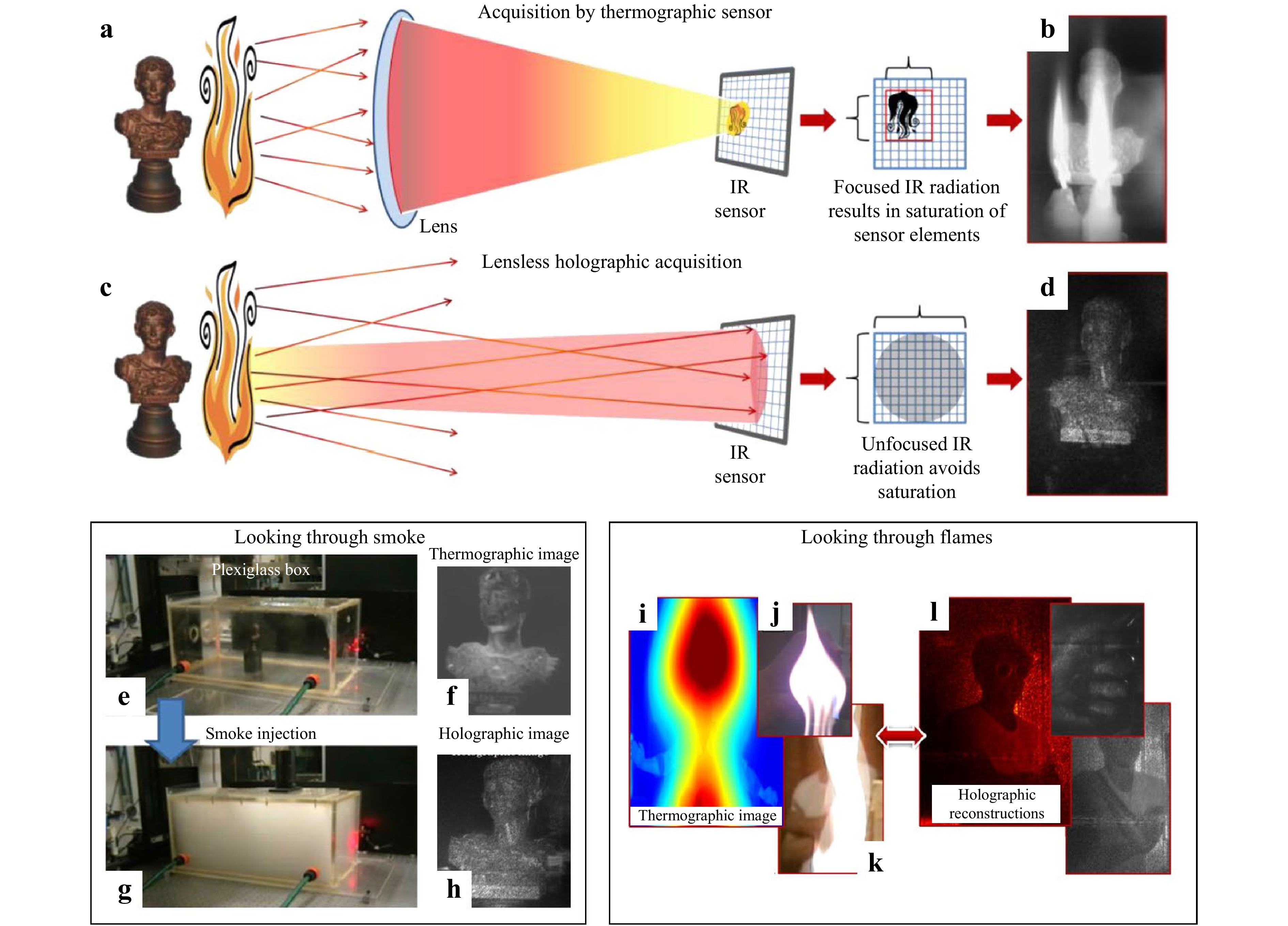
Fig. 2 Looking through smoke and flames. a Classical thermographic imaging scheme; b LWIR lensless DH acquisition scheme; c A thermographic image obtained with the statuette behind a flame; d Holographic reconstruction after numerical refocusing at the distance of the object. (The figure is adapted from figures of Ref. 36, by permission of OSA)
Here the authors use the off-axis DH configuration. They can isolate the object in a part of the reconstruction plane and reconstruct the image thanks to a single hologram. This configuration is well suited for dynamic events, where the thermo-optical disturbance is rapidly changing. By its incoherent nature, the thermal emission is present in the zero-order, thus not reconstructed in the image after the spectral filtering.
The authors also used the same principle to image an object (the statuette) surrounded by smoke, as is shown in the bottom left medaillon. The object is enclosed in a plexiglass box (transparent at 10 µm), Fig. 2e. It is possible to record a thermographic image in these conditions, Fig. 2f. When the box is filled with smoke, Fig. 2g, the object is not visible anymore, although it is possible to reconstruct the holographic image, Fig. 2h.
Finally, the most impressive application concerns the observation of a living human behind a flame, as is shown in the bottom right medaillon. Fig. 2i shows the thermographic image: the subject is not observable because the image is blinded by the flame. This is also the case with images taken in visible, Fig. 2j, k where the subject is barely visible. As is shown in Fig. 2l, applying LWIR DH allows the reconstruction of the image of the subject behind the flame and to recognize it is a human being.
The large size of reconstructed objects, as already stressed earlier, is put in evidence in this application. Recently the group demonstrated a self-referenced configuration easing setup portability41.
-
HI is a method that can be used for monitoring the thermo-mechanical behaviour of space structures undergoing temperature changes, similar to those experienced during space flight. One project funded by the European Space Agency (ESA) aimed at measuring up to hundred-micrometre level deformations that occur on the meter-sized space aspheric reflectors. The idea was to use DH to perform phase measurement at different temperatures during thermal cycling in a vacuum chamber simulating space environments14.
We already stressed that, in LWIR, objects appear more specular than in the visible range. In the ESA application, reflectors intended for far-infrared/sub-mm wavelengths were to be tested. They mostly appeared specular in the visible. Therefore, we needed to consider the design of a DH interferometer for specular objects. A constraint was that the laser and the camera are not vacuum-compatible and must be kept out of the vacuum chamber.
Fig. 3a shows the design of the DH interferometer. Details of its development are given elsewhere14. In brief, the configuration is inline DH, which maximizes the resolution in the reconstructed image. The expanded and collimated laser beam enters the vacuum chamber through a window W. The beam is split by BS1 into two parts. The reference beam travels to sensor S through the beam combiner BC and passes by a folding mirror mounted on a piezo translator (MPZT) for applying phase-shifting. After BS1, the object beam illuminates a reflective diffuser D. The scattered light illuminates the reflector, a parabolic mirror with a 1.1m diameter and 1.58m focal length. The mirror reflects specularly the speckled wavefront towards the camera sensor through the beam combiner and a second window W. A set of lenses L1 to L6 are in the various paths for adapting the dimensions of the beams while relaying the images from inside the chamber to the camera.
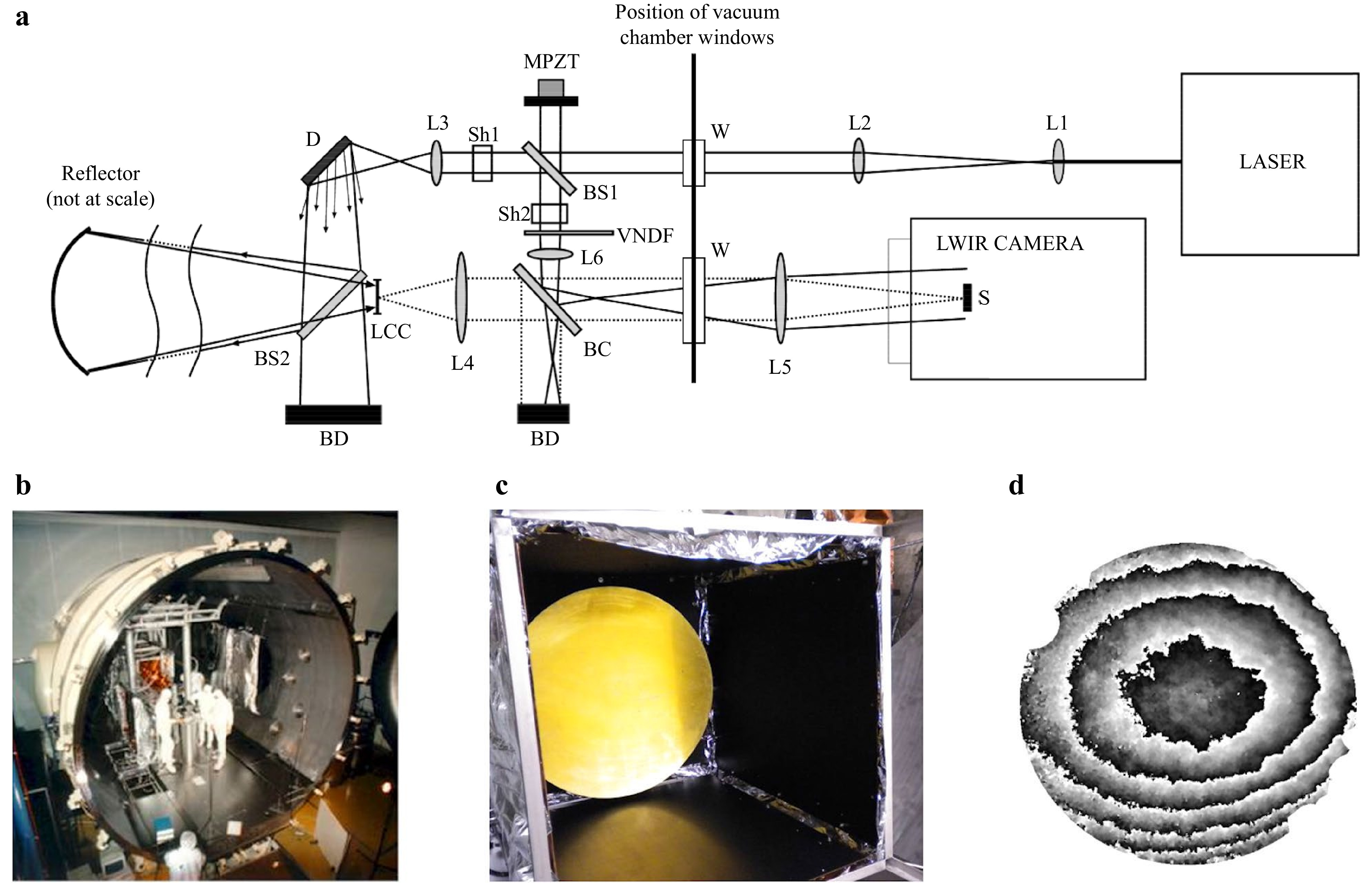
Fig. 3 Measuring large deformation of large space reflectors by inline LWIR digital holographic interferometry. a Sketch of the interferometer adapted to vacuum-chamber operation; b View of the vacuum chamber; c The 1.1m diameter gold-coated reflector in a thermal shroud for radiative transfer; d Phase map mod 2
$ \pi $ showing the deformation of the reflector from 224 K to 107.5 K.Fig. 3b shows a picture of the 5 m diameter vacuum chamber where the experiment was implemented. Fig. 3c shows the gold-coated aspheric mirror in a thermal shroud allowing temperature variations by radiative transfer. The rest of the interferometer (except the camera, the laser and three lenses) was placed inside the chamber and kept at ambient temperature. Fig. 3d shows the phase difference modulo
$ 2\pi $ due to the deformation of the mirror between 224 K and 107.5 K. Excellent agreement was found between this measurement and another taken with a classical infrared interferometer adapted explicitly to the reflector.A second application of the same technique concerned the cryogenic test of a 4 × 4 mosaic of detectors used of the EUCLID space mission, Fig. 4a. It was required to measure the global deformation of the ensemble, the deformation of each detector as well as the displacement of each of them with respect to their neighbors42. The range of deformation was 20 µm which is compatible with LWIR DHI. Also, since relative piston movements between sub-assemblies are to be sought, we incorporated the temporal phase unwrapping to follow the phase of each pixel independently to their neighbours. In this project, the setup was redesigned for coping with the new object. The latter is roughly flat, and the diffuser D to be used must be at least as large as the object. The setup is shown in Fig. 4b, with again the laser and the camera outside the vacuum chamber. Details about the experiment and the results can be found in Ref. 42. Fig. 4c shows a 3D plot of the residual deformation of the detectors mosaic.
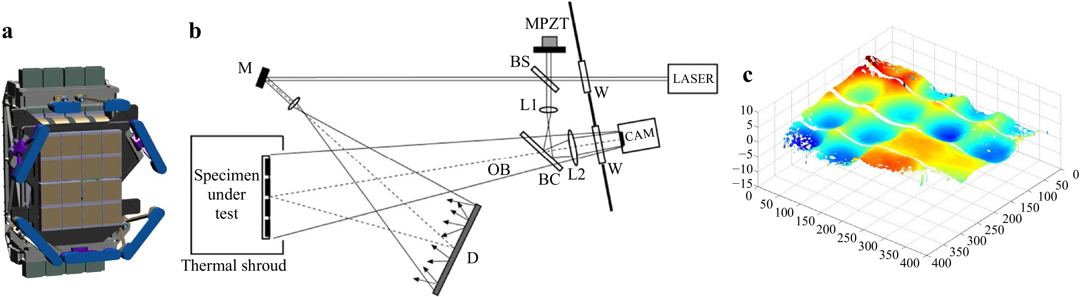
Fig. 4 Measuring deformations and rigid body motions of detectors arranged in a 4 × 4 mosaic for the EUCLID space observatory. a Drawing of the mosaic of detectors in its mechanical holder; b Sketch of the interferometer adapted to vacuum-chamber operation; c Phase map mod 2
$ \pi $ showing the residual deformation from 293 K to 90 K. -
As discussed in the thermal self-emission subsection, it is possible to record both the thermal background image of an object together with its hologram. The only condition is to use an image holography configuration, i.e. with a lens focusing the object image on a sensor. In that sense, speckle interferometry responds to this condition. It is related to digital holography, except that the processing does not make use of numerical refocusing.
Using phase-shifting allows retrieving phase in the usual way (for the holographic part), and the temperature background is obtained through the addition of the phase-shifted holograms34. Doing so for different object states, we can compute the respective optical phases and the thermal backgrounds and calculate their differences. Once proven in the lab, this concept was implemented in a mobile instrument for in-field NDT29, 43. Fig. 5a−c shows the principle of the instrument. Details are given elsewhere29. In brief, it is composed of a lower bench Fig. 5a, with the CO2 laser and a polarization beamsplitter (PBS), detailed in Fig. 5b. A part of the beam is used to illuminate the object. The remaining reference beam is directed to the upper bench, Fig. 5c, where it is directed to the camera through a beam combiner BC and a retroreflecting mirror CM. The camera receives the light through BC as well as the reference beam. The instrument is shown in blue in Fig. 5d.
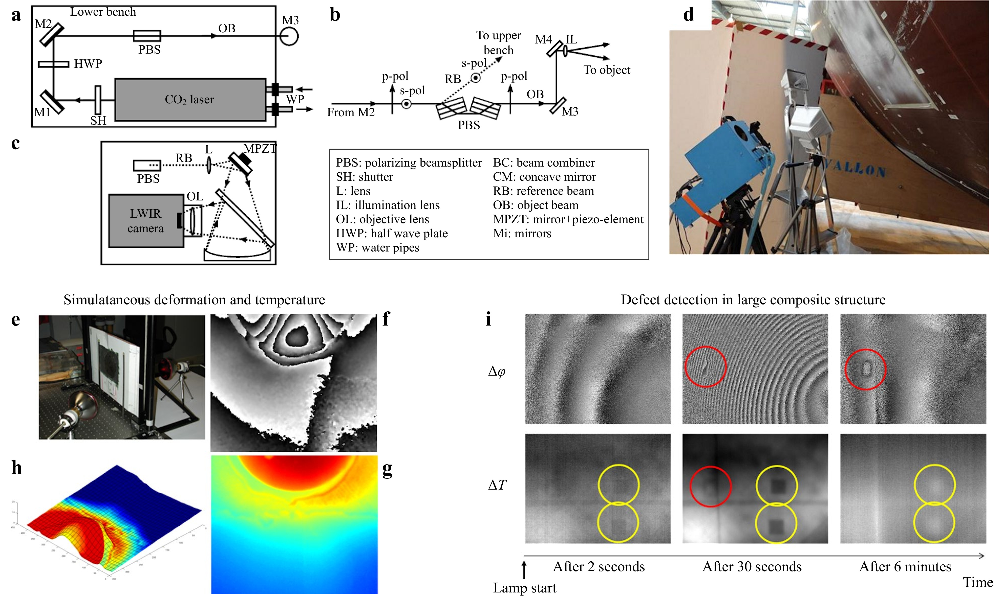
Fig. 5 Mobile LWIR speckle interferometer: a lower bench with laser, b upper bench with camera, c beam separation and object illumination. d The system when used for NDT experiment on large composite aircraft structure. e Helicopter composite structure with central repair, f interferogram due to deformation after thermal heating, g simultaneous temperature variation, h hybrid view of deformation and temperature variation. i Defect detection on large aircraft composite structure by simultaneous deformation and temperature variation measurement.
The bottom right medallion shows the first laboratory demonstration of simultaneous deformation and temperature variation measurement. Fig. 5e shows the object: a composite panel with a repaired part (dark area). The structure is heated thanks to infrared lamps on both sides of the object. Fig. 5f, g show respectively the phase map related to the deformation and the temperature change. We have both information at every pixel simultaneously, Fig. 5h, which is an advantage compared to separate systems measuring deformation and temperature independently. This was used in a variety of applications for determining the thermo-mechanical behaviour of materials.
The most impressive application was the use of the instrument at an aircraft testing plant on a full-scale composite fuselage, as seen in Fig. 5d. The zone observed is seen coated with scattering removable powder. The convex shaped surface could not allow a homogeneous scattering profile.
The fuselage incorporates some artefacts simulating internal damages. Fig. 5i shows the deformation (phase map
$ \Delta \varphi $ ) and the temperature change obtained at different instants during a step heating of a few tens of seconds. We can see defects appearing in the deformation signal (defects circled in red) while they are not visible in the thermal signal, and conversely (defects circled in yellow).The instrument was later adapted to vibration measurement44, but temperature variations were not found sufficiently high to be put in evidence.
-
Developing THz DH offers another way of performing THz imaging, a flourishing realm over the last two decades40,45,46. The first development of DH with THz radiation originated from the low-frequency (sub-THz) range. Dated back to 2004, an off-axis THz digital hologram was recorded with a 100 GHz Gunn diode oscillator and a single-point Schottky Barrier Diodes (SBD) detector47. In 2008, Tamminen et al.48 proposed a THz reflective off-axis DH setup using a vector network analyzer as transmitter and receiver at 310 GHz to image a metallic target placed 1.5 m away from the detector. In 2011, Heimbeck et al.49 realized THz off-axis DH with a tunable frequency-multiplied microwave synthesizer and an SBD single-point detector in the range 0.66−0.76 THz. The frequency tunability of the THz source allowed them to apply the well-known dual-wavelength approach to eliminate the
$ 2\pi $ phase ambiguity problem.Full-field was the inevitable trend for THz DH and other possible coherent lensless imaging techniques. However, at the sub-THz range, the long wavelength requires very large 2D arrays with adequate sensitivity for sub-THz radiation50.
On the other hand, despite the selective penetration ability in the FIR range, which limits the further application, the band is more suitable for investigating emerging coherent lensless imaging techniques with commercially available 2D thermal FPA arrays in single-shot without tedious raster-scanning using a single-point detector. In 2011, Ding et al. reported the first full-field off-axis THz DH setup with a FIRL laser and a pyroelectric camera at 2.52 THz with a lateral resolution of 3.4
$ \lambda $ 51. The first THz inline DH was performed in 2012 by the same research group52.Since this first successful demonstration, the THz coherent lensless imaging became an active research area. Thermal FPAs paired with FIR CW sources became the mainstream equipment for investigating full-field DH imaging techniques.
After the above proof-of-concept demonstrations, the development of THz DH devoted itself to further improving the imaging performance, notably in resolution enhancement. In terms of DH recording, besides minimizing recording distance for resolution enhancement, the synthetic aperture (SA) technique was successfully implemented with both off-axis53, 54 and in-line55, 56 configurations, making up for the insufficient size of THz detectors. For inline THz DH, efforts have been mainly made on reconstruction algorithms towards better reconstruction quality57,58,59.
As the imaging ability is maturing, THz DH has been gradually carried out towards application. Similar to visible wavelengths, due to the specificity of the setup, inline THz DH was solely implemented in digital holographic microscopy (DHM) fashion for biomedical applications, seeing through sparse samples. The testing samples have transitioned from dehydrated insect specimens to cancerous tissue. In Ref. 60, the reconstruction of a human hepatocellular carcinoma tissue slice (Fig. 6a) proved that early signs of liver cancer and diseases could be traced using THz inline DH.

Fig. 6 THz inline digital holographic reconstructions. a Photograph of the object, a human hepatocellular carcinoma tissue; b Reconstructed absorption and c phase shift after numerically extrapolating the holograms recorded via sub-pixel registration method. The green arrow indicates a cut across a vessel or a region damaged after freezing the object. The blue arrow indicates a vertical line which is a sign of tissue fibrosis (Figure adapted from Fig 3 and Fig 4 of Ref. 60, by permission of Sci. Rep.)
The reconstructed phase after resolution enhancement revealed a sign of tissue fibrosis (the blue arrow in the phase map in Fig. 6c), making THz inline DH a promising tool for cancer diagnosis. Off-axis THz DH offers a wider choice of samples, thus more application scenarios, thanks to the independent reference wave. The samples can be measured in both transmission and reflection mode. In transmission mode, thickness measurement of optically opaque materials at FIR range was carried out in Refs. 61, 62. At the Sub-THz range, visualizing the void in a 3D-printed sample has been demonstrated at 0.495 THz25, 63. A depth of 45 µm was clearly distinguished from the phase image. On the other hand, imaging concealed objects using off-axis DH under reflection mode paves the way to applications in non-destructive inspections. In Refs. 64, 65, real-time imaging of moving metallic objects hidden by a thin yet rigid plate made of optically opaque yet highly transparent (PE or PP) has been successfully demonstrated, as shown in Fig. 7c, d adapted. However, despite the encouraging results, the perturbation caused by the interaction between complex cover materials and the samples still needs to be tackled before meeting the challenge of real-world industrial inspection applications66. The FOV of the reconstruction scene remained on a cm-scale. Moreover, the reflectivity and the transmittance of both the imaging target as well as the cover materials is also an important concern in terms of applications67.
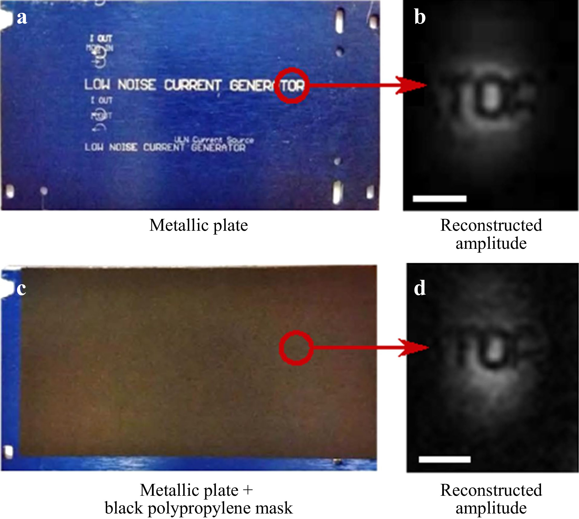
Fig. 7 Real-time imaging concealed object using reflective off-axis THz DH. a Photograph of the object, a metallic plate with inscriptions; b Reconstructed amplitude of the object at one position during its movement; c Photograph of the plate cover; d Reconstructed amplitude of the concealed inscription. (Figure adapted from Fig. 1 Ref. 64, by permission of Sci. Rep.)
-
This overview shows that using wavelengths much longer than the visible spectrum in holography can bring many advantages, tackling some apparent issues. In particular, all applications in LWIR show that holography can work efficiently under industrial conditions, even in a harsh outdoor environment. Furthermore, wavelength also plays a central role in metrology where it sets the sensitivity of the holographic interferometry method: large displacements can be measured more easily with a decent resolution. This was put in evidence in real-life projects for testing large space structures undergoing significant temperature variations.
In addition, we have seen that particular behaviour appears with long wavelengths. First, objects tend to be specular, which is not an advantage. However, this can be mitigated up to some point by using removable scattering powder, when possible, or illuminating objects through diffusers. Second, specifically in LWIR, thermal emission appears, corresponding to ambient temperature. This incoherent background can be naturally filtered out, but it can also be used appropriately to perform simultaneous deformation and temperature measurements. It was used advantageously in aeronautical NDT on the sizeable composite fuselage.
We have seen that long wavelengths penetrate the matter better. In LWIR, human-size objects illuminated through smoke or flames can be refocused under a lensless DH configuration. In THz, light can penetrate a wide range of solid materials. Thus, DH with THz radiation allows imaging objects concealed by these visually opaque materials.
Despite all these advantages and outstanding applications, there is a price to pay. We discussed a fundamental limit that is related to the ratio of the pixel pitch of state-of-art cameras and the wavelength. These aspects hold true from LWIR ranges to THz ranges. In LWIR, larger objects can be observed with acceptable resolution when working at wavelengths longer than visible wavelengths for a given recording distance, assuming lensless Fresnel DH. However, due to the limited size of array detector in THz, keeping acceptable resolution requires placing the objects very close to the detector, limiting the applicability of Fresnel DH. Other DH reconstruction methods, such as ASM or convolution, can be used on objects of centimetric sizes, such as those found in the biomedical field, as was demonstrated in cancer detection, which is by far the most appropriate application of THz DH in the FIR regime. On the other hand, the Sub-THz regime is the band where we can make the utmost use of the penetration ability to develop seeing-through applications. However, the lack of sufficiently large and sensitive array detectors limits the development of Sub-THz DH towards application. More industrial applications can be envisaged with the availability of large and sensitive array detectors for Sub-THz.
In the visible range, wavefront shaping components such as spatial light modulators (SLMs) will offer more possibilities in DH, such as self-interference incoherent DH. For instance, a proof-of-concept multispectral incoherent DH experiment has been demonstrated in IR range68. The maturing of IR and THz SLMs technologies will push these methods towards applications.
-
M.G. and Y.Z. acknowledge European Regional Development Fund/Wallonia region project (TERA4ALL); MG. and JF.V. acknowledge the support of ESA (GSTP project Contract No. 22540/09/NL/SFe) and EU (FP7 European project FANTOM ACP7-GA-2008-213457).
Holography in the invisible. From the thermal infrared to the terahertz waves: outstanding applications and fundamental limits
- Light: Advanced Manufacturing 3, Article number: (2022)
- Received: 15 September 2021
- Revised: 07 March 2022
- Accepted: 08 March 2022 Published online: 11 April 2022
doi: https://doi.org/10.37188/lam.2022.022
Abstract: Since its invention, holography has been mostly applied at visible wavelengths in a variety of applications. Specifically, non-destructive testing of manufactured objects was a driver for developing holographic methods and all related ones based on the speckle pattern recording. One substantial limitation of holographic non-destructive testing is the setup stability requirements directly related to the laser wavelength. This observation has driven some works for 15 years: developing holography at wavelengths much longer than visible ones. In this paper, we will first review researches carried out in the infrared, mostly digital holography at thermal infrared wavelengths around 10 micrometers. We will discuss the advantages of using such wavelengths and show different examples of applications. In nondestructive testing, large wavelengths allow using digital holography in perturbed environments on large objects and measure large deformations, typical of the aerospace domain. Other astonishing applications such as reconstructing scenes through smoke and flames were proposed. When moving further in the spectrum, digital holography with so-called Terahertz waves (up to 3 millimeters wavelength) has also been studied. The main advantage here is that these waves easily penetrate some materials. Therefore, one can envisage Terahertz digital holography to reconstruct the amplitude and phase of visually opaque objects. We review some cases in which Terahertz digital holography has shown potential in biomedical and industrial applications. We will also address some fundamental bottlenecks that prevent fully benefiting from the advantages of digital holography when increasing the wavelength.
Research Summary
Holography at long invisible wavelengths allows outstanding applications
Marc Georges from Université de Liège reviews researches and developments on digital holography at wavelengths much longer than the visible ones, mainly between 10 µm and 120 µm. Long wavelengths applied to quantitative phase imaging, in particular holography, can bring many advantages and open the way to new applications. Obviously, holography is better immune to environmental perturbations, hence can be used on the field, even in exterior. Thermal infrared wavelength allow penetrating visually opaque gases, making possible reconstruction of scenes occluded by smoke. Moreover, holographic interferometry incorporate the natural thermal emission in the hologram. This improves nondestructive testing applications on very large industrial parts. After these successes, it was natural to migrate towards larger wavelengths with Terahertz waves, which allow penetrating many solids for searching occluded artefacts. However, some fundamental limits are reached and discussed.


Rights and permissions
Open Access This article is licensed under a Creative Commons Attribution 4.0 International License, which permits use, sharing, adaptation, distribution and reproduction in any medium or format, as long as you give appropriate credit to the original author(s) and the source, provide a link to the Creative Commons license, and indicate if changes were made. The images or other third party material in this article are included in the article′s Creative Commons license, unless indicated otherwise in a credit line to the material. If material is not included in the article′s Creative Commons license and your intended use is not permitted by statutory regulation or exceeds the permitted use, you will need to obtain permission directly from the copyright holder. To view a copy of this license, visit http://creativecommons.org/licenses/by/4.0/.

 DownLoad: