


-
Coded aperture imaging (CAI) technologies offer imaging capabilities and dimensionalities beyond the limits of conventional lens-based imagers1. In a lens-based imager, an object point is mapped to a distinct point on the sensor if the object point lies within the depth of focus. Since this is a point-to-point mapping, resulting in the formation of an image of the object directly on the sensor, the lens-based imagers are called direct two-dimensional (2D) imagers. For this reason, it is crucial to produce high-quality lenses with as minimum aberrations as possible. In CAI methods, every point of an object is mapped by an optical modulator to a unique 2D intensity distribution. Any change in the location of the point changes the 2D intensity distribution. Only linear, shift-invariant systems are considered here, and so any change in the lateral direction only shifts the 2D intensity distribution, and a change in the axial direction changes the 2D intensity distribution. This linearity exists for the intensity of light in the case of incoherent imagers. This study is focused only on imaging systems with spatially incoherent and high temporally coherent illumination that includes sources such as light- emitting diodes, fluorescent sources, and also natural light with chromatic filters. In all the experiments discussed next, only critical illumination is considered. When a thick object is made up of multiple points in three-dimensional (3D) space with P observed planes along the Z-axis, the resulting object intensity distribution is formed by the summation of shifted and scaled point spread intensity distributions given as
$ {I}_{O}=\sum _{p=1}^{P}{I}_{PSF,p}\otimes {O}_{p} $ , where$ {O}_{p} $ is the object intensity at plane p, ‘$\otimes $ ’ is a 2D convolution operator and$ {I}_{PSF,p} $ is the point spread intensity distribution at the plane p. Consequently, the object information at a plane p can be reconstructed as$ {O}_{p} $ =IO*$ {\hat{I}}_{PSF,p} $ , where ‘*’ is the 2D correlation operator, and$ {\hat{I}}_{PSF,p} $ is a processed version of$ {I}_{PSF,p} $ . The above relation can be modified as${O_p} = \sum\nolimits_{k = 1}^P {{I_{PSF,k}}} \otimes {O_k} * {\hat I_{PSF,p}}.$ So, the reconstructed image of the object consists of two correlation terms, namely$ {I}_{PSF,p}\ast {\hat{I}}_{PSF,p} $ and$ \sum _{m\ne p}^{P}{I}_{PSF,m}\ast {\hat{I}}_{PSF,p}, $ which are the autocorrelation and cross-correlation terms respectively, where m is non-zero integer sampling the out-of-focus planes. For 3D imaging, the point response should yield a sharp autocorrelation delta-like peak and low cross-correlation values, enhancing the strength of the object information at the plane of interest and suppressing the object information from other planes. Such a property is present with scattered light, where the speckles formed by scattering in the far-field have an average size of the diffraction-limited point spread function of a direct imaging system with the same numerical aperture. This last feature makes CAI attractive for 3D imaging2. Based on the interesting properties of scattered light, most of the recent CAI methods converted the light diffracted from an object into a random wave to encode 3D information of the object in a 2D matrix3-5. The introduction of chaos in the form of a random phase (or amplitude) mask converts the light from an object into a speckle pattern and transforms a 2D imager into a 3D one. In most of the previous studies2-4, the engineering of chaotic apertures is not discussed in detail. While some of the methods3,5 did not engineer the apertures, it is evident from the previous studies1,4, that engineering of chaotic apertures is crucial to control the imaging characteristics of CAI systems. Some of the review articles1,6 mentioned aperture engineering. However, a detailed review of chaotic aperture engineering methods and their role in controlling imaging characteristics have not been discussed. In this article, we review some of the engineering approaches of chaotic apertures and describe how the characteristics of chaos manipulate the imaging characteristics of the system. -
The optical configuration of the CAI method is shown in Fig. 1a. Light from an object is incident on an optical modulator that scatters the object wave, and the scattered intensity distribution is recorded by an image sensor. The object and image distances are zs and zh, respectively. Let us consider a single point in the object plane at
$ \overline{{r}_{o}}=({x}_{o},{y}_{o}) $ with an intensity Io. The complex amplitude reaching the optical modulator is given as$ {C}_{1}\sqrt{{I}_{o}}L(\overline{{r}_{o}}/{z}_{s})Q(1/{z}_{s}) $ , where$ (x,y) $ are the modulator’s coordinates,$ L(\overline{{r}_{o}}/{z}_{s})= $ $ \mathrm{e}\mathrm{x}\mathrm{p}\left[j2\pi \right({x}_{o}x+{y}_{o}y)/(\lambda {z}_{s}\left)\right] $ and$Q(1/{z}_{s})=\mathrm{e}\mathrm{x}\mathrm{p}[j\pi ({x}^{2}+{y}^{2})/ $ $ (\lambda {z}_{s})]$ are the linear and quadratic phase functions, respectively, and C1 is a complex constant. The complex amplitude of the optical modulator is Mexp(jΦ), where M is a constant for a phase-only modulator and for a pinhole array Φ is a constant and$M = \sum\nolimits_{n = 1}^N {\delta \left( {x - {x_n},y - {y_n}} \right)} $ , where$ ({x}_{n},{y}_{n}) $ are set of random locations, and N is the number of pinholes. The complex amplitude after the optical modulator is$ {C_1}\sqrt {{I_o}} L\left( {{{{{\bar r}_o}} \mathord{\left/ {\vphantom {{{{\bar r}_o}} {{z_s}}}} \right. } {{z_s}}}} \right)Q\left( {{{\text{1}} \mathord{\left/ {\vphantom {{\text{1}} {{z_s}}}} \right. } {{z_s}}}} \right)M{\text{exp}}\left( {j\Phi } \right). $ The scattered intensity distribution, which is the PSF for a point at zh from the optical modulator over the plane$ {\bar{r}}_{h}, $ is,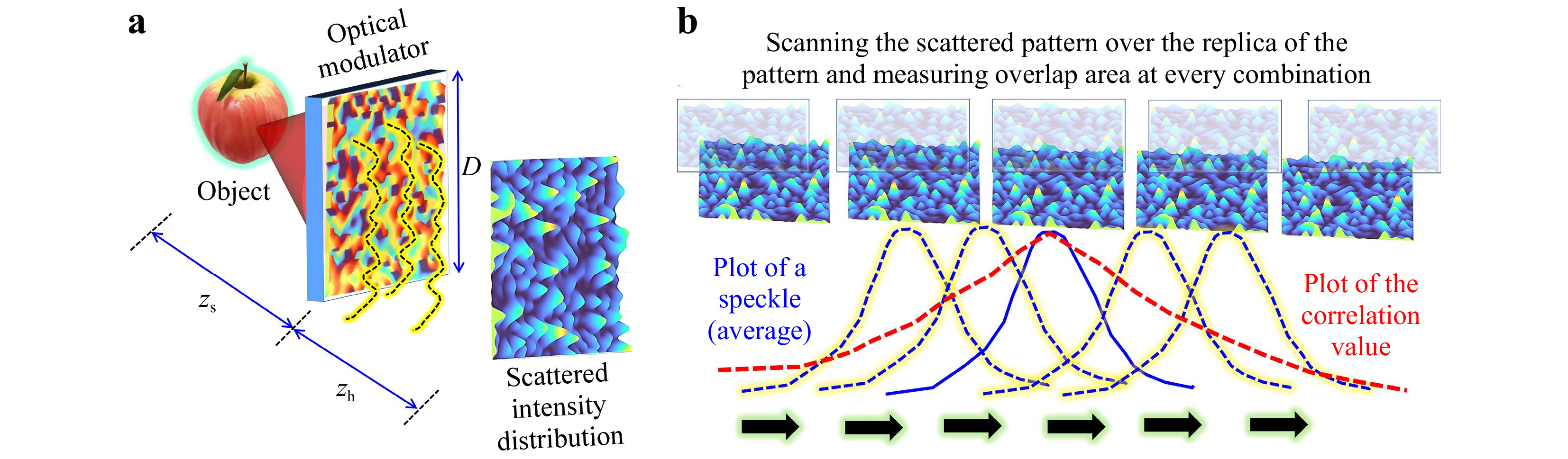
Fig. 1 a Optical configuration of simplified coded aperture imaging method. b Autocorrelation operation.
$$ {I}_{\mathrm{P}\mathrm{S}\mathrm{F}}\left(\overline{{r}_{h}};\overline{{r}_{o}},{z}_{s}\right)={\left|{C}_{1}\sqrt{{I}_{o}}L\left(\frac{\overline{{r}_{o}}}{{z}_{s}}\right)Q\left(\frac{1}{{z}_{s}}\right)M\mathrm{e}\mathrm{x}\mathrm{p}\left(j\mathrm{\Phi }\right) \otimes Q\left(\frac{1}{{z}_{h}}\right)\right|}^{2} $$ (1) -
The lateral resolution limit of a direct imaging system is the width of the diffraction-limited spot obtained in response to a point in the input, which is 1.22λzs/D. In the case of CAI methods, the lateral resolution is given by lateral correlation length Ll given as twice that of the average speckle size2. Note that the resolution is defined in the object plane rather than the observation plane. Therefore, the scaling factor zs/zh between the (virtual) speckle pattern on the object plane and the (real) speckle pattern on the observation plane is applied. The correlator measures similarities between two patterns: the higher the similarity, the higher the correlation value, and vice versa. The cross-correlation operation of the intensity distribution obtained for a point object over the replications of the same pattern is illustrated in Fig. 1b. The width of the correlation peak is twice as much as the average speckle size, i.e., Ll=2.44λzs/D. So, the lateral resolution of CAI methods is only half of that of a direct imager. The regular correlation operation, which is equivalent to spatial filtering with the matched filter, has a lateral correlation length equal to twice that of the diffraction-limited spot in the far-field. The matched filter can be mathematically expressed as
$ {I}_{R}=\Bigg|{\mathcal{F}}^{-1}\Bigg\{{\Bigg|{\tilde{I}}_{\mathrm{P}\mathrm{S}\mathrm{F}}\Bigg|}^{\alpha}\exp\Bigg[iarg\Bigg({\tilde{I}}_{\mathrm{P}\mathrm{S}\mathrm{F}}\Bigg)\Bigg]{\Bigg|{\tilde{I}}_{o}\Bigg|}^{\beta }\exp\Bigg[-iarg\Bigg({\tilde{I}}_{o}\Bigg)\Bigg]\Bigg\}\Bigg| $ , where$ {\tilde{I}}_{\mathrm{P}\mathrm{S}\mathrm{F}} $ and$ {\tilde{I}}_{o} $ are Fourier transforms of IPSF and Io, respectively, α = 1 and β = 1. It was shown in 1984 that a phase-only filter when α = 0 and β = 1 generated a sharper correlation peak than the matched filter7. Most recently, a non-linear correlation method was developed where the values of α and β were tuned until a minimum entropy was obtained8. The entropy is given as$ -\sum \sum \phi \left(m,n\right) $ $ log\left[\phi \left(m,n\right)\right], $ where$ \phi \left(m,n\right)=\left|C\left(m,n\right)\right|/\sum _{M}\sum _{N}\left|C\left(m,n\right)\right| $ , (m,n) are the indexes of the correlation matrix, and C(m,n) is the correlation distribution. This approach was able to reach the diffraction-limited spot size during reconstruction with a computational resolving power of twice that of a matched filter. The non-linear correlation is manifested by choosing β≠1 since it is easy to see that the operation$ {\left|{\tilde{I}}_{o}\right|}^{\beta } $ for β≠1 does not satisfy the superposition principle.The above analysis can be directly extended to the axial resolution. In CAI methods, the axial resolution is given by the axial correlation length La. As the lateral correlation length changes in the same fashion as a diffraction-limited spot, the axial correlation curve follows the same profile as that of a direct imager. Hence, the axial correlation length is the same as the axial resolution of a direct imager. The procedure for obtaining the axial correlation curve is shown in Fig. 2. However, one outcome is that neither the lateral nor axial resolutions of the CAI method are dependent upon the scattering degree of the optical modulator defined as the ratio between the length of the scattered pattern b to the maximum length B in the Fourier plane. This phenomenon is not unexpected because the influence of the scattering degree of the modulator in the far-field is expressed by the overall size of the light intensity pattern. On the other hand, the average speckle size at the far-field is dictated by the aperture size of the modulator, and consequently, the lateral and axial resolutions are determined by this aperture size. Let us demonstrate this concept by simulation of the optical fields using Eq. 1 for different levels of chaos. In this study, only thin scatterers are considered, and the scattering degree is characterized by the ratio b/B shown in the Gerchberg-Saxton algorithm (GSA) in Fig. 3a9. In this simulation, a positive lens function was integrated into the optical modulator so that the far-field is obtained at the focal plane of the lens and the near-field (Fresnel region) is some range between the focal plane and the optical modulator. The IPSF was simulated for σ variation from 0 to 1 in steps of 0.01, and the Ll was measured from the limits of the Fresnel diffraction region to the far-field regime. The map of variation of Ll for different σ and distances measured from the optical modulator to the sensor is shown in Fig. 3b. The plot of axial correlation values obtained at the origin (x = 0, y = 0) of IPSF(z=0)
$ \ast $ IPSF(z) for different σ is shown in Fig. 3c. From Fig. 3b, c, it is seen that in the far-field, there is no influence of σ on the imaging resolutions. It must be noted that the above conditions of lateral and axial resolutions are independent of the modulator type: amplitude or phase. In the far-field, the lateral and axial resolutions depend only on the aperture diameter of the modulator.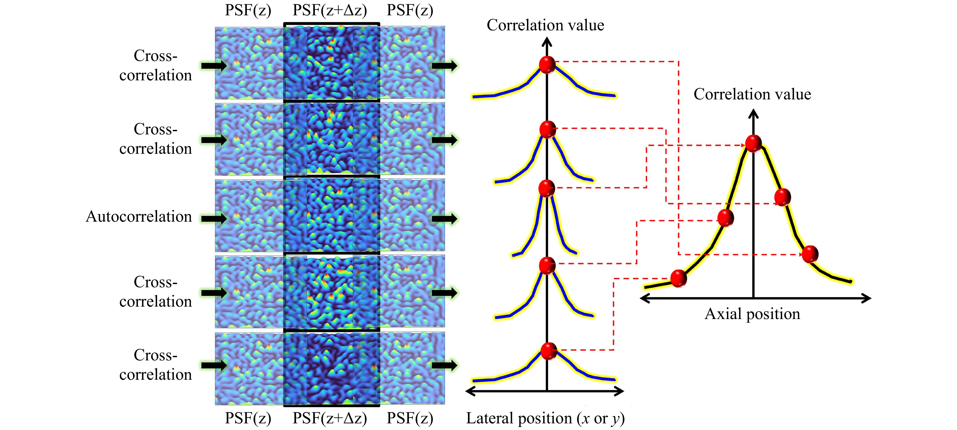
Fig. 2 Procedure for obtaining the axial correlation curve for CAI methods.
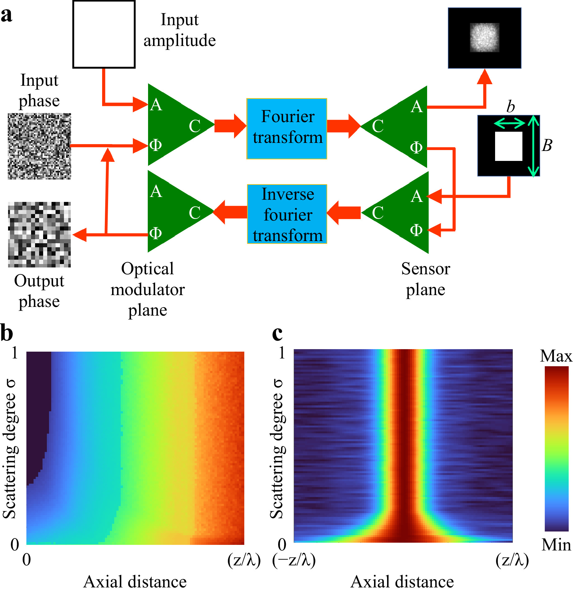
Fig. 3 a Schematic of the phase retrieval algorithm for synthesizing phase masks with a certain σ. b Map of Ll versus the scattering degree and axial distance from the optical modulator to the sensor. c Axial correlation curve obtained by a cross-correlation of the speckle pattern obtained for different locations of a point object with a reference location indicated as z = 0 at the origin (x = 0, y = 0) for different values of σ.
-
In this article, the terms super-resolution and resolution enhancement have been used interchangeably to indicate an increase in resolving power obtained by modifying the MTF in two ways: Extending the bandwidth by increasing the cut-off frequency of the modulation transfer function (MTF) and improving the MTF response for higher spatial frequencies but without changing the spatial bandwidth. This section deals with the improvement of the resolution by magnifying the response for higher spatial frequencies. The next section deals with extending the bandwidth. One of the straightforward methods to increase the imaging resolutions of CAI systems is to decrease the average speckle size. A phase retrieval algorithm was designed to generate sub-diffraction spots by introducing a π phase shift between consecutive pixels in the sensor plane and redistributing part of the light away. This approach enabled the generation of sub-diffraction spots. A phase mask was designed such that the diffraction from the mask generated randomly distributed sub-diffraction spots. When the CAI method was applied using this mask, a resolution enhancement of 1.26 times compared to direct imaging was obtained10,11. This method was called resolution enhanced coded aperture correlation holography (RE-COACH). The optical configuration of RE-COACH is similar to the one shown in Fig. 1a. The images of the phase mask and intensity distribution on the sensor plane are shown in Fig. 4a−d, respectively. The imaging results of RE-COACH, interferenceless COACH (I-COACH), and direct imaging of a United States Air Force (USAF) resolution target (Group 5 element 6, Group 6 element 1 and 2) are shown in Figs. 4e−g respectively. The lateral resolution of RE-COACH is seen higher (6.96 μm, Group 6 element 2) than both I-COACH (7.82 μm, Group 6 element 1) and direct imaging (8.77 μm, Group 5 element 6). The spot density mentioned in Fig. 4 is defined as the ratio between a number of arranged spots to a number of potential spot positions. It was noted here that if the spot density increased, the lateral resolution decreased. So, it was crucial to control chaos such that the spots do not overlap and increase the lateral correlation lengths. The imaging results of RE-COACH for different values of spot density (0.009, 0.036, and 0.09) are shown in Fig. 4h−j respectively. Beyond a spot density of 0.09, the resolution began converging towards that of I-COACH. In the above study, a non-linear correlation method was applied, resulting in a resolution of the same as the width of the sub-diffraction spot. In summary, in CAI methods, one direct method to improve the lateral and axial resolution is to reduce the size of the fundamental building block – speckle of the intensity distribution. The design of the phase mask can be achieved by implementing a sub-diffraction generation approach as in Ref 10 followed by the random point generator by the GSA. By combining the sub-diffraction spots and the random point generator, random sub-diffraction spots can be generated.
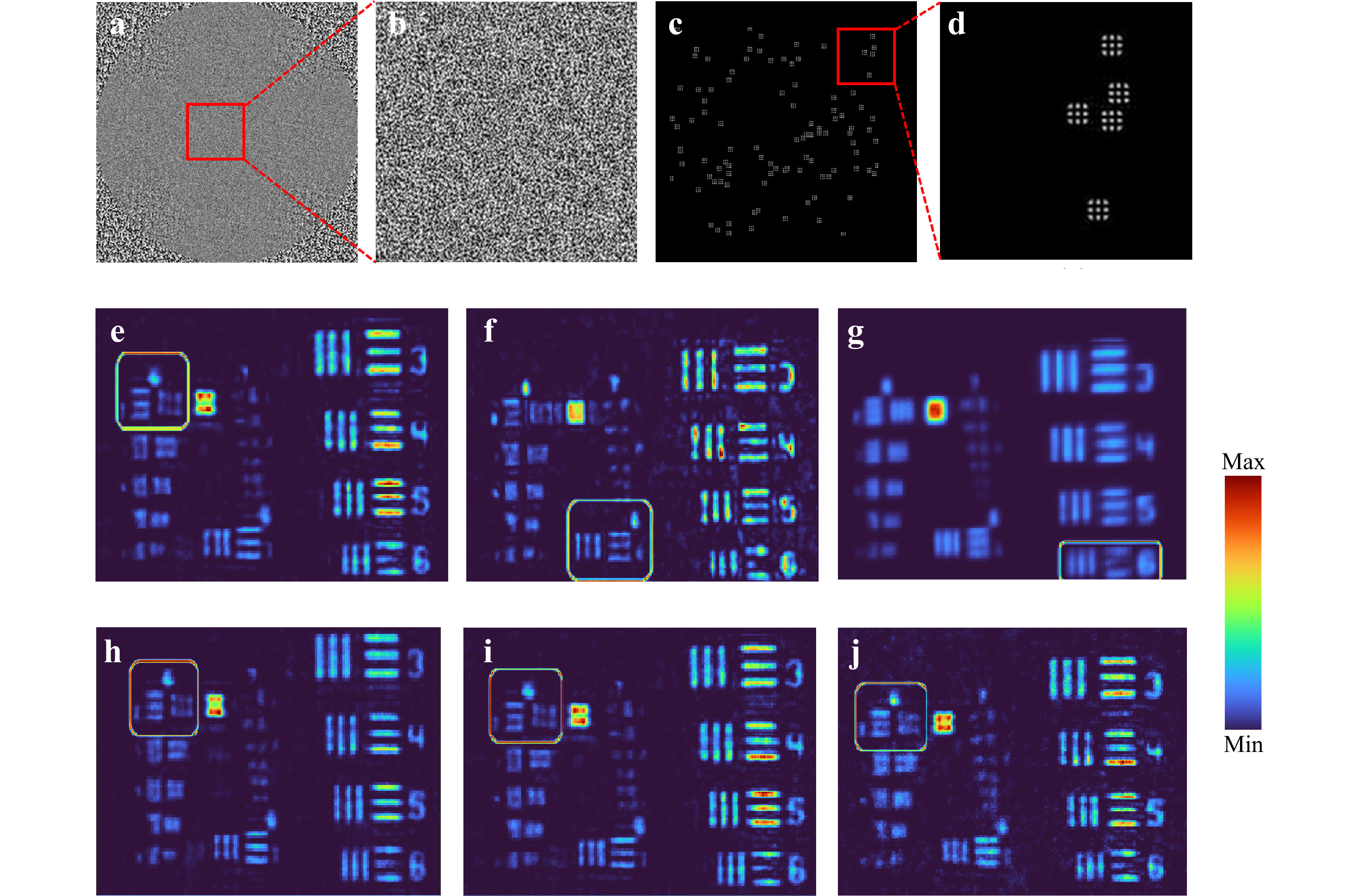
Fig. 4 a, b Images of the phase mask that generates randomly distributed sub-diffraction spots as in c and d. Imaging results from e RE-COACH, f I-COACH, and g direct imaging. Imaging results of RE-COACH for spot density of h 0.009, i 0.036 and j 0.09.
-
The previous subsection shows that introducing a chaotic phase mask into an imaging system can improve the lateral and axial resolutions without altering the spatial bandwidth. In this section, the resolution enhancement based on extending the bandwidth has been discussed. A similar concept was first demonstrated by Choi et al. by introducing turbid media into a lens-based imaging system12. The reconstruction mechanism was cumbersome, involving the recording of intensity patterns at various angles. A different approach was attempted by Kashter et al13., where a chaotic phase mask was introduced into a well-established incoherent holography technique called Fresnel incoherent correlation holography (FINCH)14. This technique is called coded FINCH (C-FINCH). In this study, a thin scatterer was introduced in between the object and a FINCH system, and the resolution of the system was studied when the scattering degree was increased. Later the concept was generalized to regular lens-based imaging systems15. The optical configuration of the imaging system is shown in Fig. 5a. The light diffracted from an object consists of information of different spatial frequencies of the object. The smaller features of the object diffract light at larger angles while the larger features diffract at smaller angles. The finite diameter D of the entrance pupil can collect only until a certain level of spatial frequencies, which sets the resolution limit of the system. By introducing a thin scatterer in between the object and the aperture of the entrance pupil, it is possible to scatter the higher spatial frequencies, which are beyond the numerical aperture, back into the system and by that to increase the lateral resolution. In the current configuration, it is possible to decrease Ll from 1.22λ(z1+z2)/D1 to 1.22λz1/D2, and by tuning the scattering degree of the modulator σ between 0 to 1, it is possible to reach new resolution limits. Five objects (8.98 lp/mm to 14.25 lp/mm) of USAF resolution target were imaged. The direct imaging results and reconstruction results for σ = 0.1042 and 0.1458 are shown in Figs. 5b−d, respectively. A notable resolution enhancement is seen by introducing the chaos and increasing its rank. FINCH has the capability to reach a resolution enhancement of 1.5 times that of an equivalent incoherent imaging system. The application of the above method to FINCH increased the resolution by seven times that of an equivalent incoherent imager and five times that of FINCH without chaos. FINCH has lower axial resolution compared to direct imagers, and introducing chaos significantly improved the axial resolving power13. Note that this resolution enhancement method does not change the imaging system aperture. Instead, the technique manipulates the light in the free space between the object and the entrance aperture of a given unchangeable system. In that sense, the method is equivalent to the technique of structured illumination16, in which the light between the source and the object is manipulated.
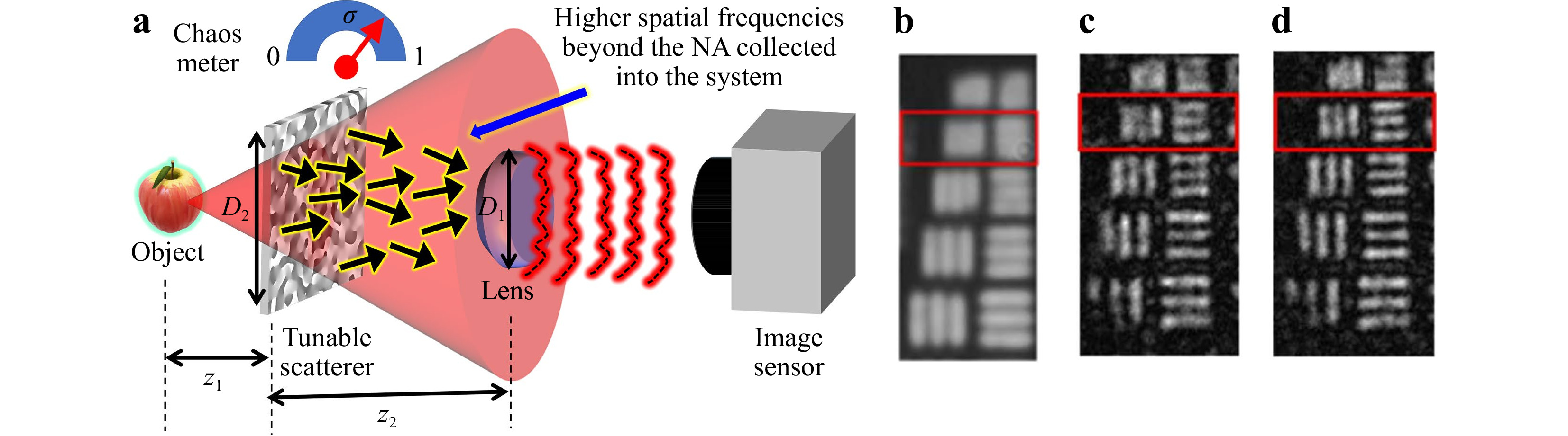
Fig. 5 a Optical configuration of the imaging system with a scatterer placed between the object and entrance pupil of the imaging system. b Direct imaging. Reconstruction results for c σ = 0.1042 and d σ = 0.1458. b−d are adapted from Ref. 15.
-
Even though the above two methods dealt with improvement in lateral resolution, the concepts are completely different. The first method described previously tailored the system’s PSF, while the latter brought in higher spatial frequencies beyond the limits of the numerical aperture. In some astronomical imaging systems, the loss of resolution is due to the use of an annular aperture instead of the full aperture17. Imaging using annular optical elements suppresses the spatial frequencies higher than zero frequency except for mild enhancement near the cut-off frequency17. The PSF and MTF for two widths of annular aperture w = r and 0.04r are shown in Fig. 6b, where r is the radius of the full aperture. It is seen that the decrease in the width of the annular aperture suppresses the higher spatial frequencies resulting in a loss of the lateral resolution. The intensity distribution of the PSF is similar to that of a magnitude square a Bessel function of the first order of the first kind. It has been found18 that if a chaotic phase mask was attached to the annular lens, then the higher spatial frequencies were not suppressed as much as in the case of only an annular spherical (or parabolic for high radius value) mirror. The PSF and MTF of the partial aperture imaging system (PAIS) for w=0.04r are shown in the third line of Fig. 6b. By comparing the MTF of the annular spherical mirror and PAIS, it is seen that PAIS has a better response to higher spatial frequencies. An experiment was carried out18 to compare direct imaging and PAIS using a spatial light modulator (SLM) consisting of 1920 × 1080 pixels and a pixel pitch of 8 μm. The imaging results for National Bureau of Standards (NBS) objects (14 lp/mm and 16 lp/mm) obtained for full aperture and a ring of 40 μm width for direct imaging and PAIS are shown in Fig. 7. It is seen that the introduction of chaos has significantly improved the resolving power of the system. It must be noted that this resolution enhancement occurs without altering the bandwidth of the imaging system. The method of PAIS was extended to synthetic aperture imaging where instead of using the full aperture, only the periphery of the aperture was scanned, but the images were reconstructed with the resolution of the full aperture19.
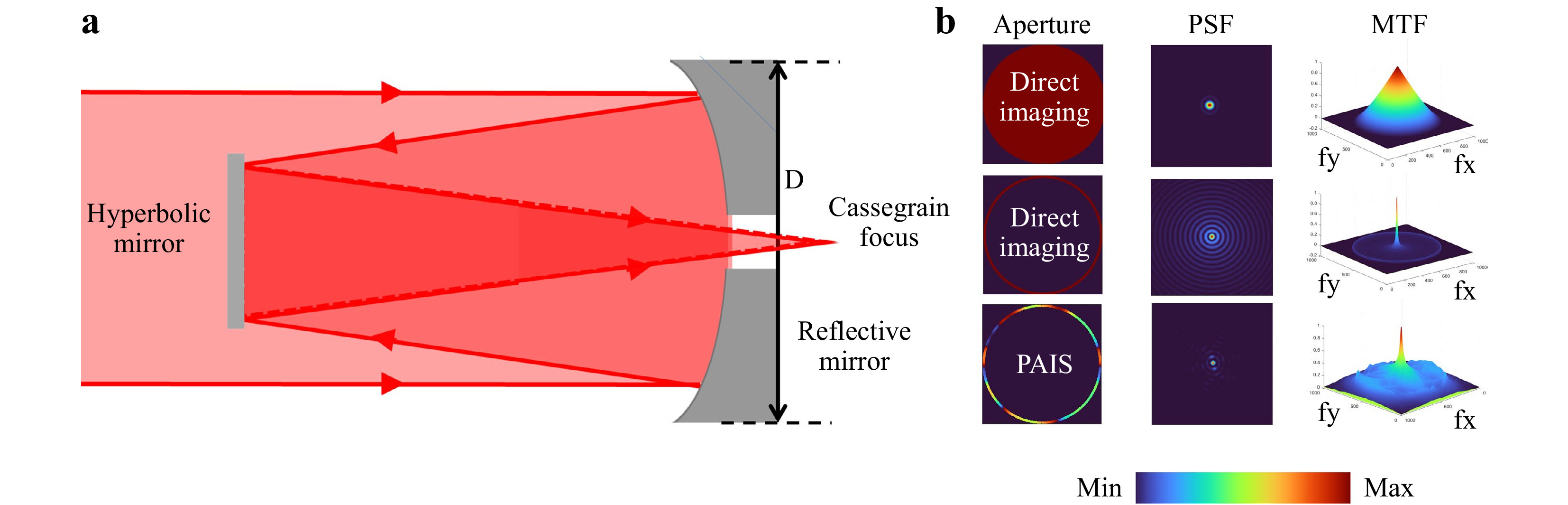
Fig. 6 a Optical configuration of Cassegrain telescope. b Images of aperture, PSF, MTF for direct imaging (w = r and w = 0.04r), and partial aperture imaging system (PAIS) (w = 0.04r).
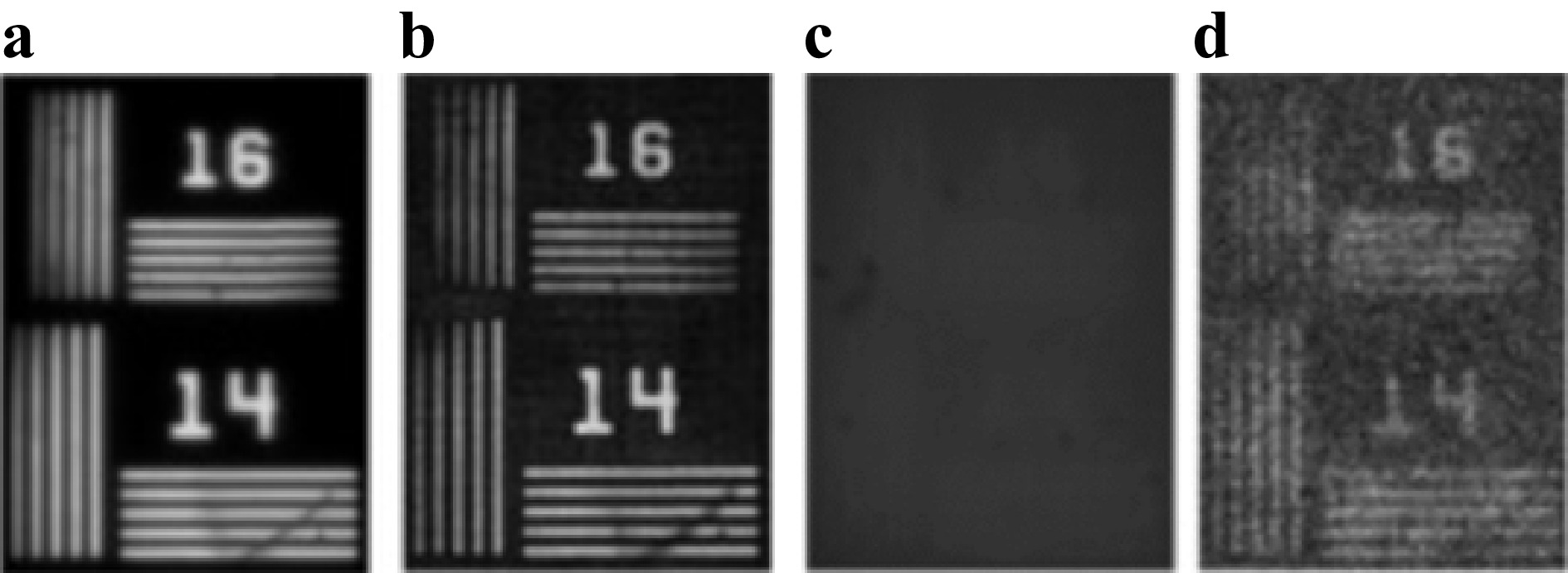
Fig. 7 a Direct imaging and b PAIS for full aperture. c Direct imaging and d PAIS for an annular aperture with a width of 40 μm. Adapted from Ref. 18.
-
The above three subsections showed how introducing and controlling the chaos could improve the lateral resolution in three different ways. In addition to improving the lateral and axial resolutions, in some cases, such as microscopy, it is useful to improve the contrast20. In this approach, two recordings were made and subtracted one from the other to improve the contrast of the reconstructed images. One recording was with a vortex filter and the other without it. Edge enhancement approaches in many incoherent holography techniques such as FINCH involved recording multiple holograms with vortex filters21. In all the above methods, the PSF of the system was recorded and utilized for reconstructing the image. In contrast, a synthetic PSF generation was proposed recently to improve the contrast of the output images22. The synthetic synthesis is a post-engineering approach, where a synthetic PSF is generated using a phase retrieval algorithm as shown in Fig. 8a. The cross-correlation with the recorded PSF produces a donut-shaped intensity distribution. Therefore, when the synthetic PSF was cross-correlated with the object intensity distribution, edge enhanced image of the object was obtained. The edge enhanced image is subtracted from the original reconstruction to generate the contrast-enhanced image of the object. If this approach is implemented to direct imaging methods, additional experiments are required, whereas here22, the contrast can be improved offline without any additional experiments. The phase retrieval algorithm starts with a random pure phase function ejθ which is multiplied with the complex conjugate of the Fourier transform of the recorded PSF and Fourier transformed. The resulting complex amplitude’s magnitude (ID) was replaced by a donut intensity obtained by a Fourier transform of a spiral phase function while the phase was retained. The resulting complex amplitude was inverse Fourier transformed and multiplied with the inverse of the complex conjugate of Fourier transform of PSF. The resulting complex amplitude was converted into a phase-only function, and the loop was iterated until the optimal synthetic PSF was obtained. The images of the PSF and object intensity distributions, phase of Fourier transform of synthetic PSF, original reconstruction, direct imaging result, edge and contrast-enhanced images of a section of a wing of an insect are shown in Fig. 8b−h, respectively.
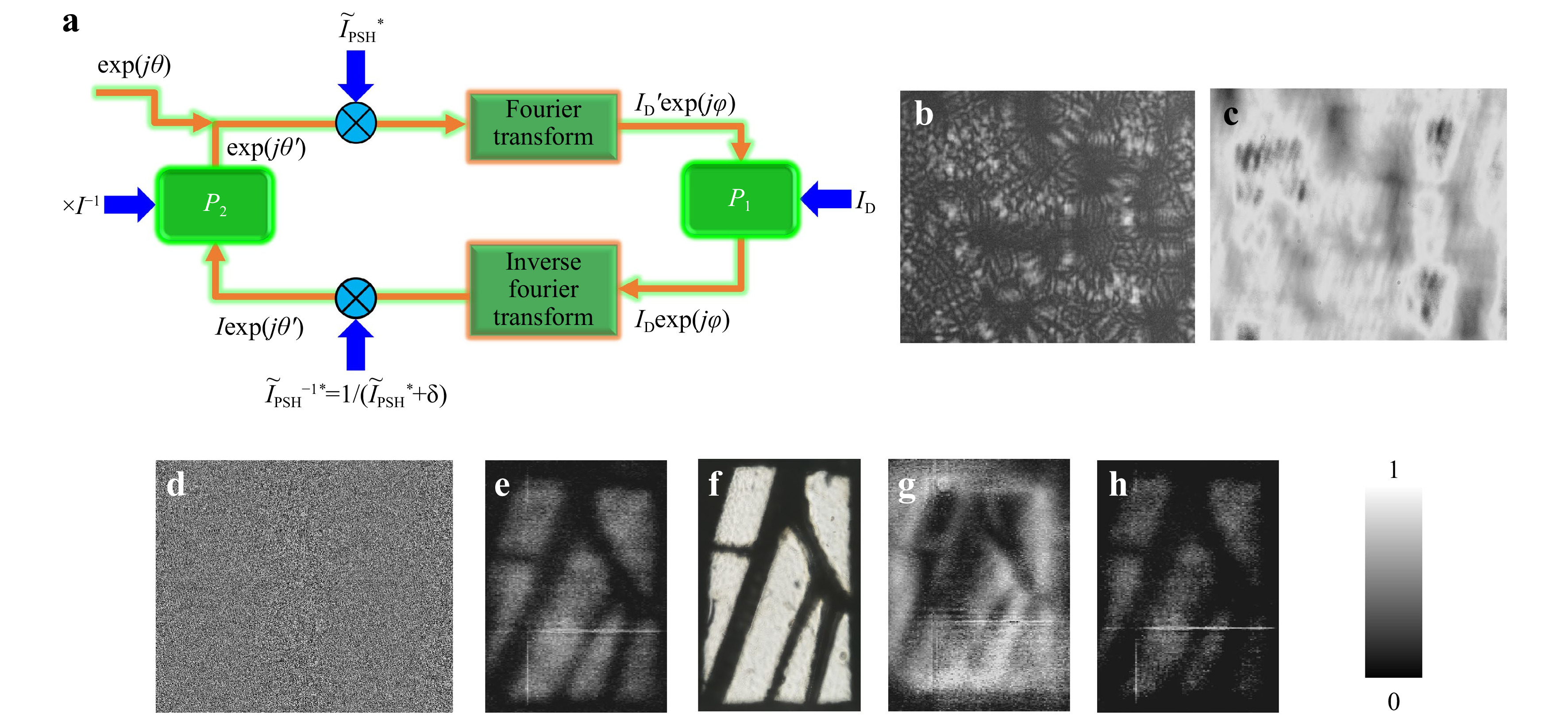
Fig. 8 a Phase-retrieval algorithm for generating the synthetic PSF. Image of the b PSF, c object intensity distribution, d synthetic PSF, e original reconstruction, f directly recorded image, g edge enhanced image and h contrast-enhanced image. Adapted from 22.
-
All the above studies were carried out using phase-only scatterers. The oldest and least expensive scatterer is the pinhole array23. A random pinhole array (RPA) maps a point in the object space to a random array of points in the far-field, but in the near field scattering (Fresnel region) of light is usually observed. The lateral resolution in the far-field should be the same for different degrees of chaos. The earlier studies1 used a phase-only scatterer generated in an active device such as SLM, and so adding a lens function was simpler. In an RPA, without the lens, in the Fresnel region, the lateral resolution is highly dependent upon the scattering degree, which is controlled by the diameter of the pinholes in the RPA. A simulation was carried out with the following parameters: zs = 10 cm, zh = 10 cm, diameter of RPA mask D = 2 mm, λ = 600 nm, and n = 100, where n is the number of pinholes, for pinhole radius varying from 10 μm to 50 μm (Fig. 1a). The simulated images of the RPA for radius r1 = 50 μm to 10 μm, and the corresponding images of the IPSFs are shown in Fig. 9a−j, respectively. It is seen from the figures that the speckle size decreases with the diameter of the pinholes. The plot of the autocorrelation function with a phase-only filter is shown in Fig. 9k. The full width at half maximum (FWHM) of the autocorrelation function is plotted in Fig. 9l. The axial resolution of the system is studied next, in a similar way shown in Fig. 2. The cross-correlation values at the origin (x=0, y=0) were calculated for the cases r1 = 50 μm to 10 μm and are shown in Fig. 10a. The FWHM of the axial correlation versus the pinhole radius is shown in Fig. 10b. Once again, a linear relationship is obtained between the radius of the pinholes and the axial resolution, and when the pinhole diameter decreases, it approaches the case of direct imaging. Unlike the far-field case where the speckle sizes were the same for all degrees of chaos, with RPA, the lateral resolution has a secondary bottleneck in addition to NA, which is the diameter of the pinhole that must be taken into consideration while designing the optical system and RPA mask. The dependence of the speckle size in the radius of the pinholes, and thus in the scattering rank, is different from the behavior of the systems of the previous sections. The difference is because the sensor plane is located in the near-field zone of the pinhole mask, where the speckles are obtained by light interference from neighbor pinholes. As much as the pinholes are small, the angle between interfering rays is large, and speckles become small.
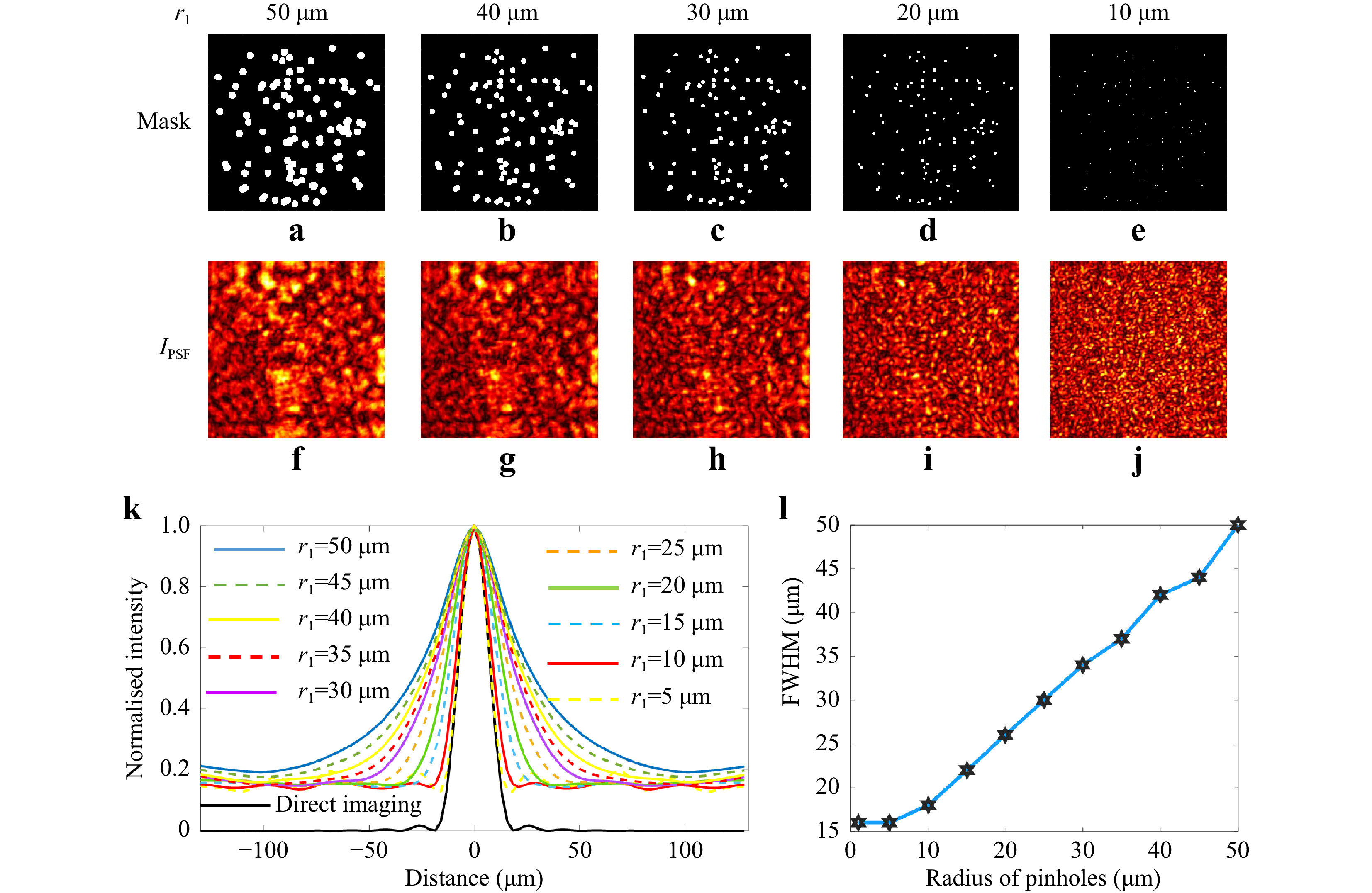
Fig. 9 Image of the RPA mask with r1 = a 50 μm, b 40 μm, c 30 μm, d 20 μm and e 10 μm and the corresponding speckle patterns f−j. k The plot of the autocorrelation function for r1 = 50 to 5 μm in steps of 5 μm. l The plot of the FWHM of the autocorrelation function for r1 = 50 to 5 μm in steps of 5 μm.
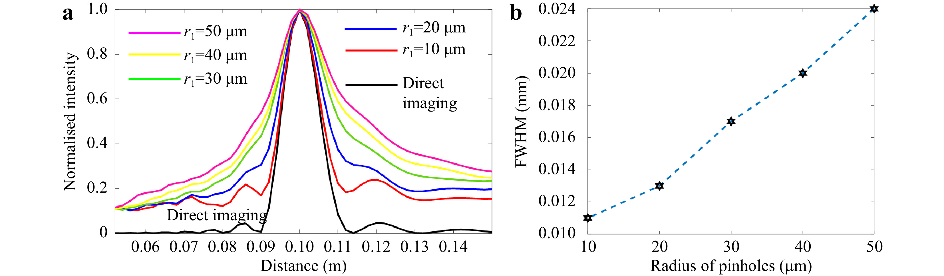
Fig. 10 a Plot of the axial correlation curve for r1 = 50 to 10 μm in steps of 10 μm. b Plot of the FWHM of the axial correlation peaks versus the diameter of the pinholes in RPA.
-
One of the main applications of CAI systems is to resolve spectral information. There were many spectral imagers based on CAI24,25. In general, the spectral resolution of a direct imaging system depends upon the spectral scanning system installed either in the source or the detector, as dispersion-based spectral sensitivity of refractive lenses is low. Three cases are considered for the same optical configuration: refractive lens, diffractive lens, and RPA. The following design parameters are considered for the comparison. zs = 10 cm, zh = 10 cm, D = 2 mm, λ = 0.4−0.8 µm (0.6 µm as design wavelength), f = 5 cm and n = 100. A refractive lens made up of silica is considered. The Sellmeier equation based on dispersion for silica is given as
$ {\mu }^{2}= 1+{{B}_{1}{\lambda }^{2}}/({{\lambda }^{2}-{C}_{1}})+{{B}_{2}{\lambda }^{2}}/({{\lambda }^{2}-{C}_{2}})+{{B}_{3}{\lambda }^{2}}/ $ $ ({{\lambda }^{2}-{C}_{3}}), $ where μ is the refractive index and the Sellmeier coefficients26 for silica are B1 = 0.6961663, B2 = 0.4079426, B3 = 0.8974794, C1 = 0.0046791 µm2, C2 = 0.0135120 µm2, C3 = 97.934002 µm2. The variation of the refractive index with wavelengths is shown in Fig. 11a. The refractive index of silica for λ = 0.6 µm is n = 1.458. The radius of curvature R using Lens maker’s formula for a biconvex lens is given as R = 2f(n − 1) = 4.58 cm. The focal length is plotted with respect to the wavelength λ = 0.4 − 0.8 µm in Fig. 11a. The radius of zones of a Fresnel lens is given as$ {\rho }_{n}\cong \sqrt{2nf\lambda } $ and so$ f\cong {{{\rho }_{n}}^{2}}/{2n\lambda } $ . For λ = 0.6 µm and f = 5 cm, the radius of the first zone is given as ρ1 = 245 µm. The focal length$ \left({6\times {10}^{-8}}/{2\lambda }\right) $ is plotted as a function of wavelength in Fig. 11a. As expected, the chromatic aberration is higher for the diffractive lens than for a refractive lens. A point object is imaged using a refractive lens, diffractive lens, and an RPA and for λ = 0.4−0.8 µm. The variation of intensity at (x = 0, y = 0, zh = 10 cm) as a function of wavelength is plotted in Fig. 11b for direct imaging with refractive and diffractive lenses. The spectral resolution dependency on the diameter of the pinholes is studied. IPSF(λ = 600 nm) is calculated and cross-correlated with IPSF(λ) for λ = 401 nm to 800 nm in steps of 1 nm. The plot of the cross-correlated intensity matrix IR(x = y = 0) for different wavelengths and for different radii of the pinholes r1 = 10 μm to 50 μm in steps of 10 μm are also shown in Fig. 11b.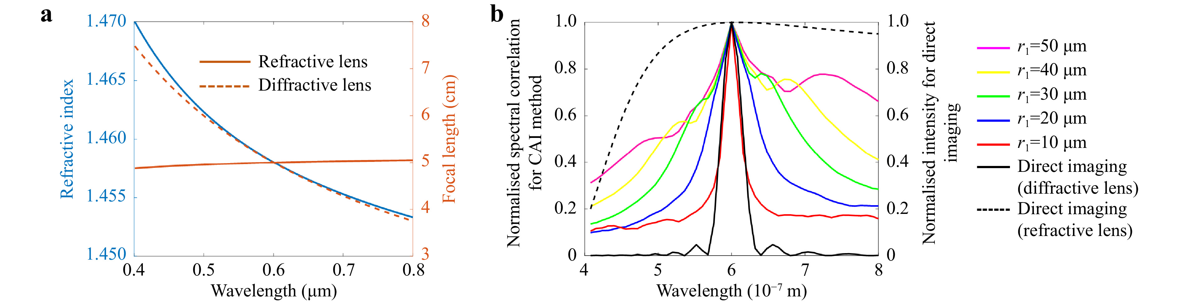
Fig. 11 a Plot of the refractive index (blue) and focal length of the refractive lens (brown-solid line) and diffractive lens (brown-dotted line) as a function of wavelength λ = 0.4−0.8 µm. b Plot of the IR(x = y = 0) for λ = 401 nm to 800 nm for r1 = 10 μm to 50 μm in steps of 10 μm for RPA and direct imaging using a refractive and diffractive lens.
From the plots, it is seen that the spectral resolutions are improved with scattering angles and match with that of a diffractive lens when r1 ≤ 10 μm. The spectral resolution of a refractive lens made of silica was the least among all three cases. Therefore, it is impossible to resolve spectral information in lens-based direct imaging systems without additional spectrum resolving components. On the positive side, the direct imaging system suffers less than other cases from chromatic aberrations. Chromatic aberration is essential for wavelength discrimination without a colour camera. In some of the recent studies, it was found that the image reconstruction quality was significantly affected when the number of spatio-spectral channels increased in CAI27. Therefore, by selecting the scattering degree, it is possible to select the number of resolvable spatio-spectral channels and control the reconstruction quality. The bias levels in the lateral, axial, and spectral correlation curves in comparison to the direct imaging are due to the correlation effects of two positive functions. The above study can also be applied to phase-only scatterers28. One of the previous studies showed that the spectral resolution of the CAI method is similar to that of a diffractive lens with the same NA28.
-
One of the important characteristics of imaging next to lateral and axial resolutions is the field-of-view (FOV) of an imaging system. The FOV of an imaging system is limited by the size of the image sensor and the magnification of the system given as ~(szs/zh), where s is the size of the sensor. In a direct imaging system, the points of the object that lies outside the FOV are not recorded by the system, as shown in Fig. 12a. The FOV in a CAI system is different owing to the indirect mode of recording and reconstruction using a PSF. In the CAI system, even when an object point lies outside the FOV, there is always some partial scattered pattern that is collected within the sensor area, as shown in Fig. 12b. Considering a typical case where the scattered intensity distribution fills at least the sensor area, the FOV of CAI systems is twice as much as a direct imager with the same magnification and identical image sensor. Therefore, by controlling the scattering degree, the FOV of the imaging system can be controlled without any limit. However, it is necessary to record the PSF beyond the sensor area by shifting the location of the sensor one time in the calibration phase.
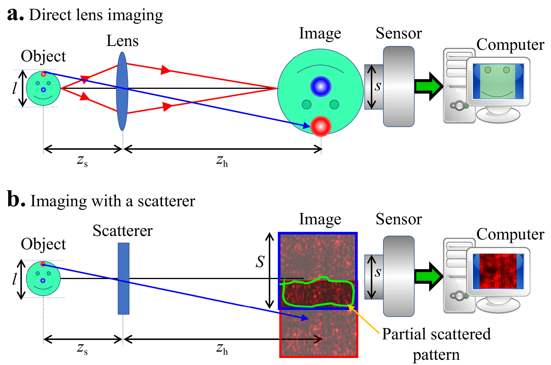
Fig. 12 Schematics of a direct imaging and b CAI for understanding FOV limitations.
The proposed technique can be applied for extending the FOV of imaging systems29,30 and the dynamic range of optical lever31-33 based on coded apertures. In both cases, the scattering degree was increased such that the area of the PSF is larger than the area of the sensor. This can be achieved by changing the window size in the GSA shown in Fig. 3a. The schematic of scanning the sensor across the PSF and recording multiple intensity distribution is shown in Fig. 13a. The resulting multiple patterns are stitched together into a synthetic PSF. The image of the recorded central part of the PSF and synthetic PSF formed by computational stitching of multiple areas of PSF recorded by scanning the sensor over the large area PSF are shown in Fig. 13b, c, respectively. The recorded object intensity distribution is shown in Fig. 13d. The reconstruction results using the regular PSF and synthetic PSF are shown in Fig. 13e, f, respectively. In conclusion, the limit of the field of view can be extended from ~(szs/zh) in direct imaging to ~(S + s)zs/zh in indirect imagers based on chaos when (S > s/2), where S is the length of the side of the scattered intensity distribution in the sensor plane.
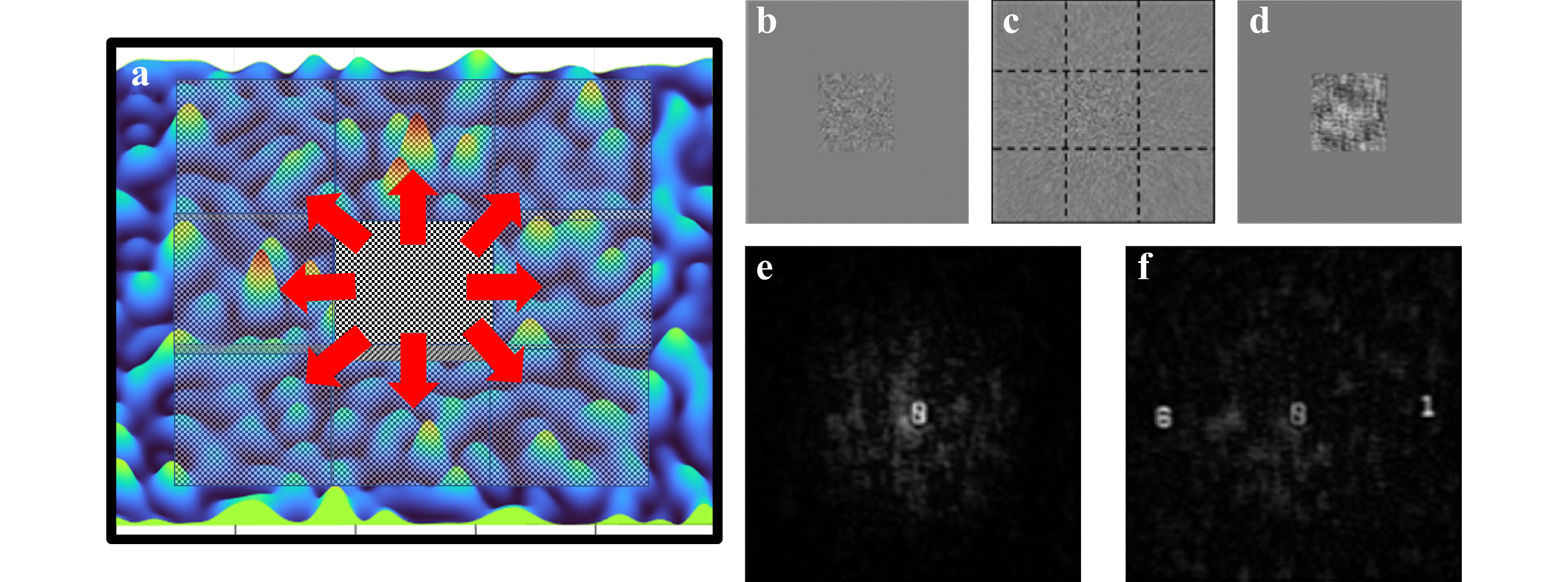
Fig. 13 a Schematic of sensor scanning approach for recording multiple areas of the large PSF. Image of b central part of PSF, c synthetic PSF, d central part of object intensity. Reconstruction results with e PSF captured within the sensor area and f synthetic PSF. b−f are adapted from 29.
-
One of the main challenges in CAI approaches is the low signal-to-noise ratio (SNR). The point-to-point mapping of direct imaging has optimal SNR. In CAI, every object point is mapped to a scattered intensity distribution. Consequently, the signal is sometimes not significantly higher than the noise level of the detector. The engineering aspects related to improving SNR are discussed next.
-
The engineering of a phase-only modulator is carried out using GSA, as shown in Fig. 3a. To control the scattering degree, it is sufficient to set a constraint in the sensor plane that the signal outside the window is zero. However, in most of the previous studies1, in addition to defining the boundary in the sensor plane, the signal within the window was set to be constant. This is a crucial factor as the background noise generated due to the correlation of two positive functions tends to be more uniform, which is often easier to deal with during computational processing than random noise. Depending upon the requirement of the imaging system, a trade-off exists between FOV and SNR. A larger FOV disperses the light to a larger area while the SNR decreases. On the other hand, a high SNR at the detector demands the light to be concentrated in a smaller area. To balance between the above contradictions, a modified configuration was selected where the light in the sensor plane was collected in the form of sparsely randomly distributed points34-36. In these studies, it was noted that as less as 5−10 dots were sufficient for imaging with significantly higher efficiency and SNR than the previous studies. However, in this case, at least two camera shots were needed to generate bipolar matrices, which during autocorrelation does not have an offset due to the presence of both positive and negative values.
-
A random pinhole array was synthesized using two uncorrelated random variables xi,yi uniformly distributed on [-C2,C2]. To reduce the background noise, quasi-random variables
$ {u}_{i},{v}_{i} $ were synthesized such that the mask consisting of the pinholes at the new locations yields images with improved SNR. The SNR is defined as Signal/(Average background noise), which becomes 1/(Average background noise) upon normalizing the reconstructed intensity pattern. The two-step optimization procedure is shown in Fig. 14a33. The random variables$ {x}_{i},{y}_{i} $ are iterated over N times, and the random variables$ {u}_{i},{v}_{i} $ corresponding to maximum SNR are selected and given as input to the second stage optimization procedure. In the next stage, the location of the pinholes is shifted along the X and Y directions with the limits$ -L\le {\Delta u}_{i}\le L $ and$ -L\le {\Delta v}_{i}\le L $ both in steps of Δ and the SNR is calculated at every step, and the quasi-random variables$ {u}_{i}\text{'},{v}_{i}\text{'} $ corresponding to the maximum SNR are determined. The second optimization, therefore, runs over 2L/Δ iterations for every location along X or Y direction. Therefore, the total number of iterations in the second optimization is 4nL/Δ.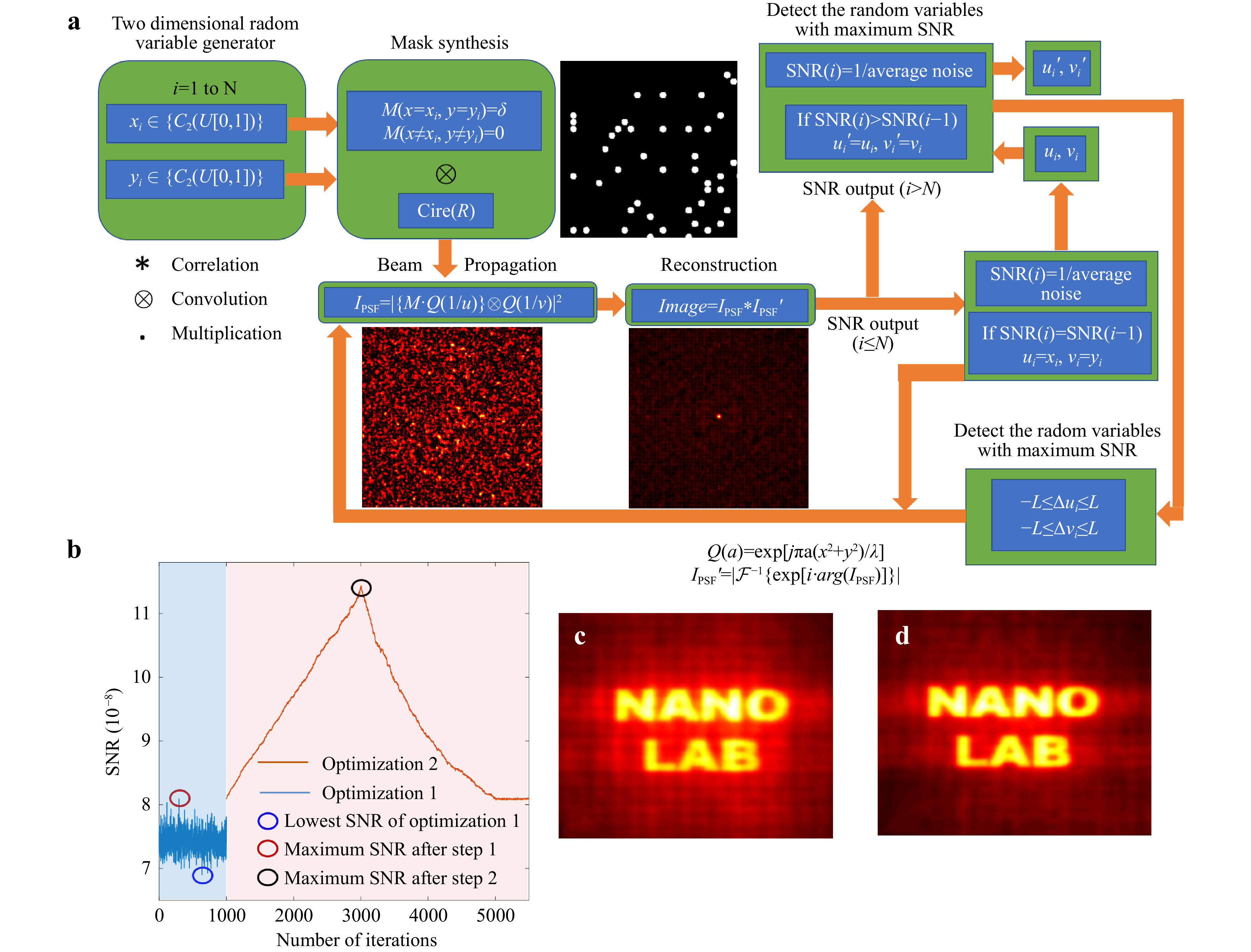
Fig. 14 a Optimization algorithm for the RPA. b Plot of SNR with a number of iterations for the two optimization steps. Reconstructed images of a test object ‘NANO LAB’ c lowest SNR after optimization 1 and d highest SNR after optimization 2.
A specific design condition of object distance (u = 10 cm) and image distance (v = 10 cm), wavelength (λ = 617 nm), pinhole diameter (d = 80 μm), mask diameter (D = 8 mm) and number of pinholes (n = 2000) is considered. During every iteration, the light from a point object propagates by 10 cm and is modulated by the RPA mask, and the modulated light propagates by another distance of 10 cm. The intensity distribution at 10 cm from the quasi RPA (QRPA) mask is correlated with a phase-only filtered version of
$ {I}_{PSF} $ such that the correlation is$ {I}_{PSF}*{I\text{'}}_{PSF} $ , where$ {I}_{PSF}^{\text{'}}=\left|{\mathcal{F}}^{-1}\left\{exp\left[iarg\left({\tilde{I}}_{PSF}\right)\right]\right\}\right|, $ and$ {\tilde{I}}_{PSF} $ is Fourier transform of$ {I}_{PSF} $ . The SNR was calculated as 1/(Average background noise) after normalizing the maximum intensity value of the correlation. The plot of the SNR with the number of iterations is shown in Fig. 14b. A test object, ‘NANO LAB’ was tested using the two masks with lowest and highest SNR, and the results are shown in Fig. 14c, d, respectively. It must be noted that there are numerous approaches available for optimizing the RPA. Some approaches involve designing coded apertures based on blue and green noise-based statistical models.24,37,38 The GSA can also be adapted where the generated optimal phase profile can be binarized and used as an amplitude mask39. The RPA can be either sparse or dense depending upon the application. While a high light throughput is desirable in most imaging systems, for monitoring high-intensity events such as industrial processes and sparks, a sparse RPA is desirable40. -
In this review, some of the engineering methods of coded aperture imaging systems that influence the different facets of the imaging, such as lateral, axial, and spectral resolutions, the field-of-view, and signal-to-noise ratio, are discussed. The coded aperture imaging is an umbrella term including both deterministic apertures such as uniformly redundant arrays (URA)23, modified URA41, Cassegrain objectives42, and randomly coded ones. This review focused mainly on the design and engineering approaches of randomly coded apertures. We have also excluded randomly coded apertures used for algorithms of compressed imaging43. Imaging through opaque scattering layers44,45 also does not belong to the present topic since these scattering layers are given apertures without the ability to code or engineer them. The multi-spectral, multi-dimensional, extended field of view and resolution enhancement imaging results demonstrating the above characteristics can be found in the original articles in the reference list. The CAI methods have many advantages over direct imaging systems, and the engineering requirements must be considered carefully to achieve optimal performance. The previously reported coded aperture imagers for spectral imaging consisted of multiple optical components such as lenses, coded apertures, and dispersive elements. In the study, the focus has been on single element coded apertures where the coded aperture acts as the dispersive element. While the single element-based coded apertures are compact, lightweight, and flexible, complicated coding abilities present in multiple component systems are difficult to achieve46. Aperture engineering approaches can also be used for improving the performances of noninvasive imaging through scattering layers44,45. As discussed in the previous sections, the lateral resolution of an imaging system is given by the width of the autocorrelation function, which is dependent upon the scattering degree of the modulator in the near field. Noninvasive imaging through scattering layers employs a phase-retrieval algorithm whose performance relies on many factors, including the scattering degree of the diffuser. In some of the studies, the scattering degree of the diffuser was increased by projecting the diffuser plane onto an SLM with a strong scattering mask using a 4f system47. In some recent studies, the need for scattering to see through obscuration based on phase-retrieval algorithms48. In some cases, the poor design of the optical modulators and design conditions will demand additional camera shots to perform statistical averaging or more complicated computational reconstruction algorithms. In any imaging system, the phase mask and optical architecture are crucial and may significantly affect the concept. A notable example is the FINCH which violates the Lagrange invariant condition at special architectures and with engineered phase masks. Another notable finding in one of the recent studies is the realization of a coherent CAI system with a simpler optical architecture as that of an incoherent CAI system by the engineering of chaotic apertures36. We believe that in the future, in addition to amplitude and phase modulations, polarization modulations in aperture engineering will play an important role in CAI systems.
-
Australian Research Council (LP190100505). European Union's Horizon 2020 research and innovation programme under grant agreement No.857627 (CIPHR).
Review of engineering techniques in chaotic coded aperture imagers
-
Vijayakumar Anand1, 2, *, ,
 ,
, -
Joseph Rosen3, *, ,
,
-
Saulius Juodkazis1, 4, *, ,
- Light: Advanced Manufacturing 3, Article number: (2022)
- Received: 05 September 2021
- Revised: 22 March 2022
- Accepted: 24 March 2022 Published online: 01 May 2022
doi: https://doi.org/10.37188/lam.2022.024
Abstract: Coded aperture imaging (CAI) is a technique to image three-dimensional scenes with special controlled abilities. In this review, we survey several recently proposed techniques to control the parameters of CAI by engineering the aperture of the system. The prime architectures of these indirect methods of imaging are reviewed. For each design, we mention the relevant application of the CAI recorders and summarize this overview with a general perspective on this research topic.
Research Summary
Expanding the imaging capabilities using engineered chaotic coded apertures
Chaotic coded apertures such as diffusers have proven to be useful for computational imaging and holography applications. Vijayakumar Anand, Joseph Rosen and Saulius Juodkazis from University of Tartu, Ben Gurion University of the Negev and Swinburne University of Technology respectively have shown the possibilities of engineering chaotic coded apertures to expand all the characteristics of imaging such as lateral and axial resolving power, field of view, signal to noise ratio and temporal resolution in an indirect imaging framework. The team developed and demonstrated different types of engineering approaches applicable to both phase-only as well as amplitude-only apertures for different types of imaging systems.


Rights and permissions
Open Access This article is licensed under a Creative Commons Attribution 4.0 International License, which permits use, sharing, adaptation, distribution and reproduction in any medium or format, as long as you give appropriate credit to the original author(s) and the source, provide a link to the Creative Commons license, and indicate if changes were made. The images or other third party material in this article are included in the article′s Creative Commons license, unless indicated otherwise in a credit line to the material. If material is not included in the article′s Creative Commons license and your intended use is not permitted by statutory regulation or exceeds the permitted use, you will need to obtain permission directly from the copyright holder. To view a copy of this license, visit http://creativecommons.org/licenses/by/4.0/.

 DownLoad: