


-
Multi-photon 3D laser micro- and nanoprinting has become a mature and widespread technology1–7. The challenges are to further boost print speed, increase spatial resolution, make more materials available, and to democratize the technology in the sense of drastically reducing cost and size of such instruments. Here, we address increasing the print speed, in terms of how many voxels can be printed per second, by a new generation of multi-photon multi-focus femtosecond-laser based instruments. We refer to voxels in the sense that their size corresponds to the two-photon Sparrow criterion, i.e., the minimum distance between two separated voxels, governed by the optical diffraction limit8. At 800 nm free-space wavelength and 1.4 numerical aperture this limit lies at around a quarter of the free-space wavelength, 200 nm, for the lateral direction and is about 2.5 times larger, 500 nm, for the axial direction8. These numbers from the two-photon Sparrow criterion are roughly equal to the corresponding full-width-at-half maxima (FWHM) of the squared intensity profile in the focus. To stay consistent with our previous work, “voxel size” without “lateral” or “axial” refers to the average of lateral and axial voxel size corresponding to the two-photon Sparrow criterion.
Broadly speaking, the print rate r in units of voxels/s (at fixed voxel size) can be increased by increasing the focus velocity of a single laser focus, by using many different laser foci (or projection of images), or by combinations thereof. The power budget is different though9,10. Increasing the focus velocity, e.g., by factor hundred leads to a hundredfold increase in print rate but only to a tenfold increase in necessary laser power for two-photon absorption. Increasing the number of laser foci by factor hundred also increases the print rate hundred-fold but requires hundred times more laser power. Therefore, it is advantageous to increase the focus velocity as much as possible technologically (may depend on the photoresist used) and only then increase the number of foci. Let us quantify these aspects further in view of the present paper. The energy per voxel needed to polymerize one voxel in units of J/voxel shall be E (which depends on the sensitivity of the photoresist9 and thereby also on the used wavelength). If one increases the print rate by increasing the number of laser foci, while keeping the photoresist and all other parameters fixed, the necessary laser power in units of W, P = rE, to be delivered into the print zone is simply proportional to the print rate r. In experiments, the power P may be technically limited by the laser power that can actually be delivered to the entrance pupil of the focusing microscope objective lens (which depends on the laser output power as well as on the power efficiency of the setup) or by the laser power that can safely be sent through the focusing microscope objective lens without damaging it. We will see that, in our present work, we approach both limits.
Our paper is organized as follows: We start by describing our next-generation setup, including the making of the diffractive optical element and the multi-lens array. Next, we characterize the intensity and the power of the foci in the array and the resulting voxel size in printing. Thereafter, we present two groups of examples, namely (i) arrays of millions of tailored 3D microparticles filling tens of cm2 substrates for potential pharmaceutical applications and (ii) large-volume mechanical metamaterials containing a record-large number of voxels in excess of 1.7 × 10¹². Finally, we bring our work into a broader context of 3D printing by adding our new results as well as other recent results into a previously established overview chart of print speed versus voxel size for various 3D printing modalities.
-
To implement a focus array for multi-photon multi-focus printing, one can choose between different beam-splitting approaches involving diffractive or refractive optics. Diffraction-based beam splitting can be performed statically with a diffractive optical element11–13 (DOE) or dynamically, e.g., with a spatial light modulator14–17. Refraction-based beam splitting by wavefront sampling can be achieved, for example, using a multi-lens array18 (MLA). These techniques are illustrated in Fig. 1a and Fig. 1b, respectively.
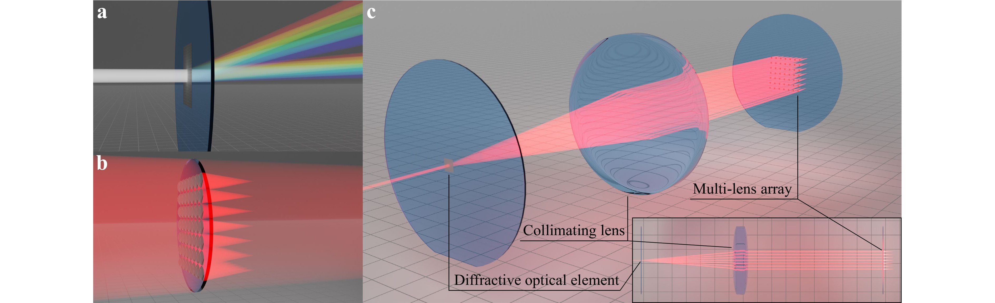
Fig. 1 Overview of different beam-splitting approaches for multi-focus printing. a rendering of a broadband laser beam illuminating a diffractive optical element (DOE) and getting diffracted into two diffraction orders. The wavelength-dependent diffraction angle fans out the incoming beam. b rendering showing a multi-lens array (MLA), which focuses a fraction of an incoming red Gaussian laser beam into an array of foci. Half of the incident laser power is transmitted without contributing to the focus array. c rendering of an incident red laser beam illuminating an $ M=3 $ DOE and getting diffracted in $ 7\times 7=49 $ single beamlets. Using a macroscopic lens, each beamlet is guided onto a single lens of an MLA consisting of $ 7\times 7=49 $ individual mini-lenses. These lenses further focus each beamlet, effectively increasing $ {M}_{\mathrm{e}\mathrm{f}\mathrm{f}} > 3 $ and creating a focus array that can be used for multi-photon multi-focus 3D printing (with only a minor spread of the foci point spread functions).
DOEs offer high resolution and power efficiency19,20, which is important in the context of the highly power-limited application of multi-focus printing. However, they still introduce conceptual issues due to their diffractive nature: When using non-monochromatic beams, each wavelength $ \lambda $ in the beam is diffracted at a different angle $ \alpha $ according to21
$$ \mathrm{sin}\left(\alpha \right)=\frac{\lambda }{g} $$ where $ g $ is the DOE spatial period or grating constant.
Fig. 1a illustrates this example by showing a broadband light source being diffracted into two orders of the diffractive optical element. Due to the finite bandwidth of the incident light, each mode has a different diffraction angle, a phenomenon referred to as angular dispersion. This aspect can become problematic when using pico- or femtosecond-pulsed beams for multi-photon printing. For example, according to the time-bandwidth product, the finite wavelength bandwidth $ \mathrm{\Delta }\lambda $ of a $ \tau =140\;\mathrm{f}\mathrm{s} $ duration sech2-shaped optical laser pulse can be calculated to $ \mathrm{\Delta }\lambda \approx 4.7\;\mathrm{n}\mathrm{m} $. This allows for an estimate of the angular dispersion introduced by the DOE when working with femtosecond-pulsed beams:
$$ \mathrm{\Delta }\alpha ={\alpha }_{1}-{\alpha }_{2}\approx \frac{\left({\lambda }_{1}-{\lambda }_{2}\right)}{g}=\frac{\mathrm{\Delta }\lambda }{g} $$ Once the angularly dispersed beamlets are focused into an array of foci, the angular dispersion broadens point-spread functions (PSFs). The magnitude of this effect obviously depends on the grating constant and therefore on the central diffraction angle. The width of this spread-out PSF $ \mathrm{\Delta }d $ with respect to the lateral focus displacement $ {d}_{\mathrm{f}\mathrm{o}\mathrm{c}\mathrm{u}\mathrm{s}} $ is given by
$$ \frac{\mathrm{\Delta }d}{{d}_{\mathrm{f}\mathrm{o}\mathrm{c}\mathrm{u}\mathrm{s}}}=\frac{f\mathrm{\Delta }\alpha }{f\lambda /g}=\frac{\mathrm{\Delta }\lambda }{\lambda } $$ Hence, the PSF broadening $ \mathrm{\Delta }d $ increases for large focus displacements $ {d}_{\mathrm{f}\mathrm{o}\mathrm{c}\mathrm{u}\mathrm{s}} $ and large spectral bandwidths $ \mathrm{\Delta }\lambda $. The equation can be related to the DOE design by introducing a new quantity M, which expresses the focus displacement $ {d}_{\mathrm{f}\mathrm{o}\mathrm{c}\mathrm{u}\mathrm{s}} $ with respect to the voxel diameter $ {d}_{\mathrm{F}\mathrm{W}\mathrm{H}\mathrm{M}} $22 and further depends on the number of DOE grating periods $ g $ in the objective lens pupil diameter D23:
$$ M=\frac{{d}_{\mathrm{f}\mathrm{o}\mathrm{c}\mathrm{u}\mathrm{s}}}{{d}_{\mathrm{F}\mathrm{W}\mathrm{H}\mathrm{M}}}=\frac{f\lambda /g}{0.567\lambda /\mathrm{N}\mathrm{A}}=0.88\frac{D}{g} $$ $$ \frac{\mathrm{\Delta }d}{{d}_{\mathrm{F}\mathrm{W}\mathrm{H}\mathrm{M}}}=\frac{\mathrm{\Delta }\lambda }{\lambda }M $$ For example, for a target focus displacement of $ {d}_{\mathrm{f}\mathrm{o}\mathrm{c}\mathrm{u}\mathrm{s}}=60\;{\text µ }\mathrm{m} $, a lateral voxel size $ {d}_{\mathrm{F}\mathrm{W}\mathrm{H}\mathrm{M}}=200\;\mathrm{n}\mathrm{m} $, and a finite wavelength bandwidth of a femtosecond-pulsed laser $ \mathrm{\Delta }\lambda =4.7\;\mathrm{n}\mathrm{m} $ at a center wavelength $ \lambda =790\;\mathrm{n}\mathrm{m} $, as used later in this publication, leads to a PSF spread for nearest neighbors in the array of
$$ \frac{\mathrm{\Delta }d}{{d}_{\mathrm{F}\mathrm{W}\mathrm{H}\mathrm{M}}}=177\% $$ This enlargement of the focal spot results in an approximate $ {\left(1.77\right)}^{2}=3.13 $-fold decrease in peak intensity and a $ {\left(3.13\right)}^{2}=9.80 $-fold decrease in two-photon absorption probability. This wavelength-dependent effect can be compensated for by using certain highly dispersive Keplerian telescopes21. However, such telescopes severely limit the available field of view (FOV) and add a large amount of group-delay dispersion into the setup, which then needs to be compensated for by an additional group-velocity dispersion unit13.
MLAs can be used for refractive beam splitting without suffering from dispersive effects, but they have other disadvantages. First, when using Gaussian beams, the focus array will have a non-uniform power distribution. Second, even when using a flat-top profile, the closest packing of MLA lenses can only focus 50% of the power of an incident beam into the focus array, as illustrated in Fig. 1b. Such power loss may be unacceptable. The use of rectangular lenses can improve power efficiency, but results in asymmetric PSFs and decreased effective numerical aperture.
The problems described with both beam-splitting approaches can be overcome by combining the DOE and MLA as shown in Fig. 1c. The incident laser beam is initially split by a DOE with extremely small M values. On the one hand, the small M values ensure low chromatic angular dispersion. On the other hand, however, small M values result in near-focus distances well below our targeted nearest-neighbor focus displacement of $ {d}_{\mathrm{f}\mathrm{o}\mathrm{c}\mathrm{u}\mathrm{s}}=60\;{\text µ }\mathrm{m} $. To compensate for the narrow focus spacing, each diffracted beamlet is relayed onto one lens of an MLA. Consequently, the MLA leverages the focus spacing. Thereby, the MLA creates a homogenous array of foci without sacrificing additional laser power. Obviously, even when using lenses of respective maximum size, the individual Gaussian beams will suffer from vignetting losses at the entrance pupil of the objective lens, only being able to use 86.5% of the incident laser intensity. In our case, we use a DOE design with $ M=3 $ together with an MLA that still allows for the desired focus displacement while having a small PSF distortion introduced by angular dispersion. We estimate
$$ \frac{\mathrm{\Delta }d}{{d}_{\mathrm{F}\mathrm{W}\mathrm{H}\mathrm{M}}}=1.77\% $$ This value is two orders of magnitude smaller than the above one and opens up the possibility of multi-photon multi-focus 3D laser printing with a large number of foci and a wide FOV. Therefore, we follow this approach. The corresponding optical setup is presented in the next section.
-
A scheme of the optical setup employed in our next generation of multi-photon multi-focus 3D laser printing using $ 7\times 7=49 $ foci is depicted in Fig. 2a. The beam of a femtosecond-pulsed Ti:Sa laser (Coherent Chameleon Ultra II; center wavelength 790 nm, average power 3.7 W, repetition rate 80 MHz, sech2-pulse duration 140 fs) is demagnified into the entrance pupil of an acousto-optic modulator (AOM, AA MT80-A1.5-IR) for fast power modulation via a 1.25× telescope consisting of lenses L1 and L2. The zeroth diffracted order of the AOM is guided into a beam dump, while the first order is imaged onto the DOE for beam splitting via a 1.60× telescope consisting of lenses L3 and L4. Ensuring the correct $ 1/{\mathrm{e}}^{2} $ beam diameter at the DOE $ {D}_{0,\mathrm{D}\mathrm{O}\mathrm{E}}=571\;{\text µ }\mathrm{m} $ with a flat wavefront is especially important for multi-focus printing applications since the beam diameter influences the design M value of the DOE. The beam parameters at this position have a large influence on the performance of the optical setup and have therefore been tuned carefully. For the design, fabrication, and characterization of the two micro-optical components, the DOE and MLA, we refer the reader to the next section.
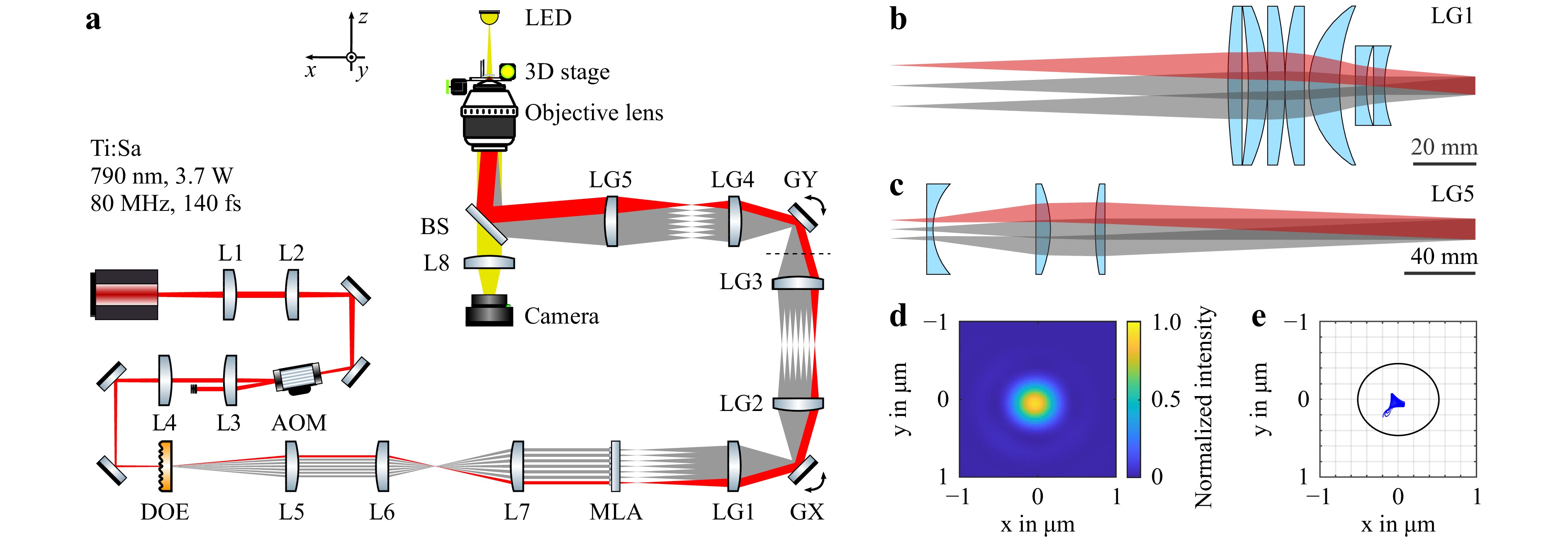
Fig. 2 Scheme and focusing quality of the used optical setup. a scheme of the optical setup employing low-dispersion beam splitting. The setup consists of a Ti:Sa laser beam (Coherent Chameleon Ultra II) that is directed onto an acousto-optic modulator (AA MT80-A1.5-IR) for power modulation. A diffractive optical element (DOE) is positioned at the beam waist and splits the incoming laser beam into $ 7\times 7=49 $ single beamlets. The beamlets are then guided onto the $ 7\times 7=49 $ individual lenses of a multi-lens array (MLA) after a magnification of the diffraction angles. Finally, the resulting focus array is imaged onto the writing plane, passing two galvanometric mirrors (GX and GY) for beam steering (via LG1 and LG2 as well as LG3 and LG4, respectively) and a relay comprising the tube lens (LG5) and the objective lens (Zeiss Plan-Apochromat 40x/NA1.4 Oil DIC). The sample translation is accomplished using a microscope stage for the x- and y-directions (Märzhäuser-Wetzlar Scan IM 120 × 100) and a piezoelectric inertia stage (PI Q-545.140) for the z-direction. The outermost beam is highlighted in red. Before GY, we flip the coordinate system, which is indicated by a dashed line. b depiction of the design for LG1 comprising seven lenses for low-aberration imaging of the homogenous focus array. The outermost beam is highlighted in red. c depiction of the design for LG5, optimized for low-aberration relaying of the incoming beamlets onto the objective lens entrance pupil. The outermost beam is again highlighted in red. d simulated point-spread function for the outermost focus of the focus array in the writing plane using optical ray tracing. e spot diagram of the outermost focus in the writing plane obtained via optical ray tracing. The black ellipse represents the Airy ellipse.
The $ 7\times 7 $ beamlets generated by the DOE are imaged through a 3.33× telescope consisting of lenses L5 and L6 to obtain the correct beamlet displacements in a compact manner. The beamlets are then telecentrically collimated by L7 to obtain a flat wavefront with the correct $ 1/{\mathrm{e}}^{2} $ beam diameter at the MLA, $ {D}_{0,\mathrm{M}\mathrm{L}\mathrm{A}}=720\;{\text µ }\mathrm{m} $, with the correct beam displacement. The lenses of the MLA focus each incident beamlet separately, effectively increasing the design M value of the DOE diffraction pattern from $ {M}_{\mathrm{D}\mathrm{O}\mathrm{E}}=3 $ to $ {M}_{\mathrm{e}\mathrm{f}\mathrm{f}}\approx 300 $ without increasing the angular dispersion. The resulting focus array is then subsequently imaged into the conjugated printing plane.
A first scan lens unit24 (LG1) collimates all incoming beamlets behind the initial focus array onto the first of two galvanometric mirrors (GX and GY; Cambridge Technology 6215H, 6 mm mirror diameter) for beam steering. A 1× telescope consisting of lens groups LG2 and LG3 images the first galvanometric mirror GX onto the second galvanometric mirror GY. A 2× telescope, consisting of the final scan lens LG4 and the tube lens LG5, finally images the collimated beamlets into the entrance pupil of a microscope objective lens (Zeiss Plan-Apochromat 40x/NA1.4 Oil DIC), which focuses them down to a $ 7\times 7 $ focus array with a nearest-neighbor distance of $ 60\;{\text µ }\mathrm{m} $. We measured the optical power in front of the objective lens entrance pupil to be $ P=954\;\mathrm{m}\mathrm{W} $. On this basis, we estimate a power of $ 19.5\;\mathrm{m}\mathrm{W} $ per focus. Furthermore, assuming a microscope-objective-lens transmission of 70% and a Gaussian focus radius $ r=\lambda /\left(\pi \mathrm{N}\mathrm{A}\right) $, with free-space wavelength $ \lambda =790\;\mathrm{n}\mathrm{m} $ and numerical aperture $ \mathrm{N}\mathrm{A}=1.4 $, this leads to an average intensity of
$$ \langle I\rangle =\frac{0.7\times P}{\pi {r}^{2}}=13.5\;\frac{\mathrm{M}\mathrm{W}}{{\mathrm{c}\mathrm{m}}^{2}} $$ and, for a repetition rate of $ {R}_{\mathrm{p}}=80\;\mathrm{M}\mathrm{H}\mathrm{z} $ and a pulse duration of $ {t}_{\mathrm{p}}=140\;\mathrm{f}\mathrm{s} $, to a peak intensity of
$$ I=\frac{\langle I\rangle }{{R}_{\mathrm{p}}{t}_{\mathrm{p}}}=1.2\;\mathrm{T}\mathrm{W}/\mathrm{c}{\mathrm{m}}^{2} $$ in each focus of the array. For clarity, the outermost beam of the array is highlighted in red. The setup is designed such that the setup uses almost the full aperture of GX and GY. In this way, the angular deflection of the two galvanometric mirrors is translated into the highest possible spatial deflection in the writing plane. Thus, the design maximizes the accessible focus scanning speed. In our previous multi-focus 3D laser printing work13, we only used about half of the available full aperture of the galvanometric mirrors.
Sample translation is accomplished by a piezoelectric inertia stage (PI Q-545.140) in z-direction and a microscope stage (Märzhäuser-Wetzlar Scan IM 120 × 100) in the xy-plane. A yellow-light LED illuminates the sample. Together with L8 and a CMOS camera (FLIR Blackfly PGE-50S5M-C), it allows for monitoring the printing process. The software based on an FPGA board for real-time control is identical to the one already published in Ref. 13.
Proper imaging of the initial focus array behind the MLA through the optical setup is especially important when using a large FOV of approximately 600 µm in diameter. Traditional scan-lens optics cause strong optical aberrations of the foci towards the edges of the focus array. To counteract these aberrations, we have developed new low-aberration lens groups using Zemax OpticStudio. The most significant design changes were made to LG1 and LG5, shown in Fig. 2a and Fig. 2b. LG2, LG3, and LG4 are similar to their previous version published in Ref. 13, 24. All individual lenses of these five lens groups were purchased separately and assembled into lens systems in our laboratory using CNC-cut spacer rings for precise positioning. To demonstrate the ideal focusing conditions, we show the simulated PSF in Fig. 2d for one of the four foci at the far corner of the array, which suffers from the strongest aberrations. The simulated spot diagram in Fig. 2e further illustrates the image quality. Neglecting tolerances, all ray-traced spots (blue dots) land inside the first Airy ellipse (black), indicating a diffraction-limited focus.
-
The combined beam-splitting approach described in the previous section requires the use of high-quality custom micro-optical components. Therefore, both the DOE and the MLA were fabricated using a Nanoscribe Quantum X two-photon grayscale lithography (2GL) system. For printing, we used Nanoscribe’s IP-S photoresist and a 25×/NA0.8 objective lens in 2GL mode. The resulting structures printed on a 2-inch diameter glass wafer are shown in Fig. 3a and Fig. 3d. We later coated the backside of the DOE as well as both sides of the MLA with a 120 nm thick layer of Al2O3 and a 140 nm thick layer of MgF2 to suppress intensity reflection losses. These decreased from 6.38% (uncoated) to 3.46% (one side coated) to 0.43% (two sides coated).
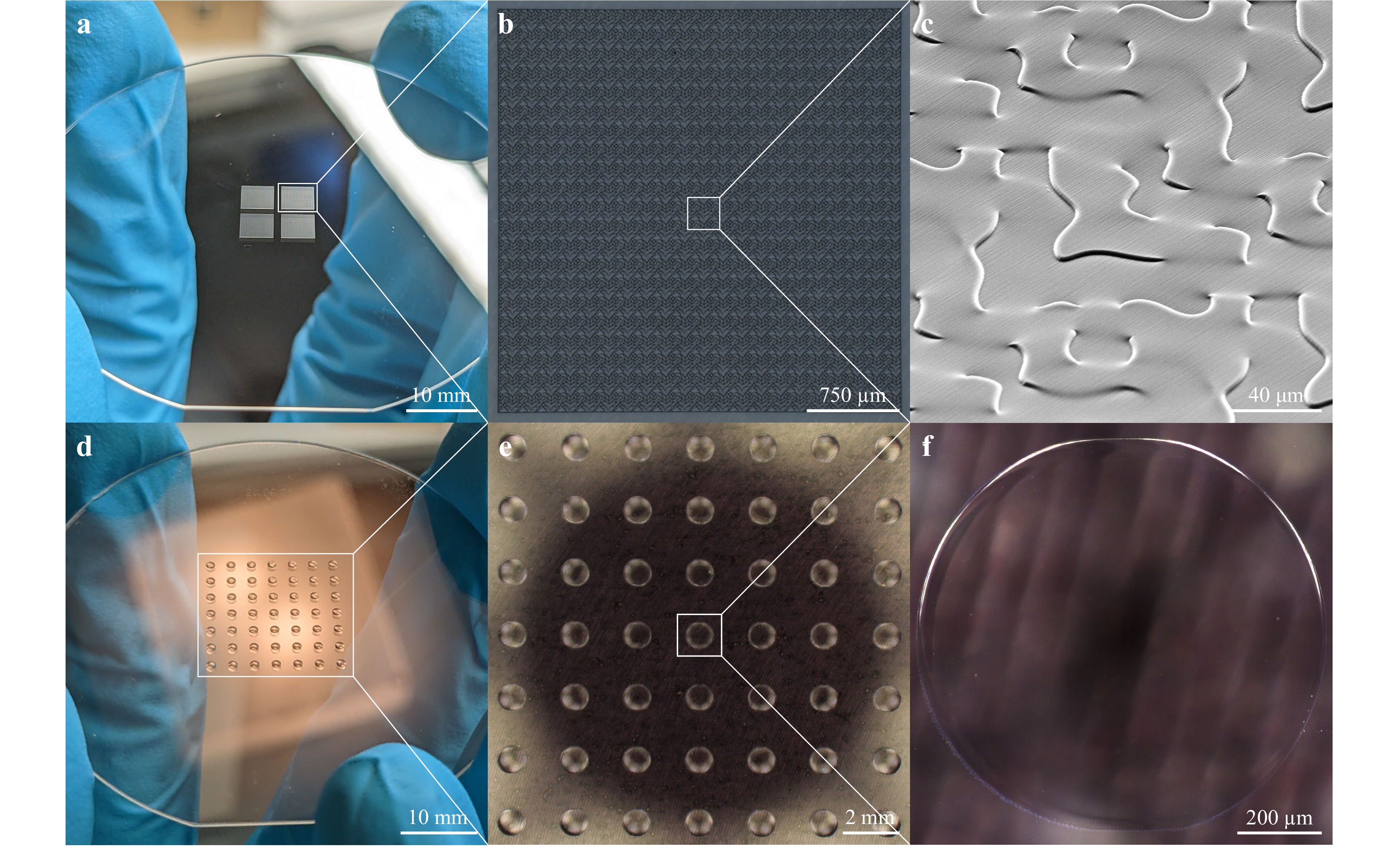
Fig. 3 Manufactured micro-optical components for beam splitting. a optical photograph of a 2-inch diameter glass wafer featuring four diffractive optical elements (DOEs) that have been printed onto it. One of these DOEs splits an incoming laser beam into $ 7\times 7=49 $ beamlets and is used in the optical setup (cf. Fig. 2). b light microscope image displaying a single DOE. Even though the printing-field size is much smaller than the DOE, no stitching artifacts are observed. c scanning-electron micrograph showing a close-up perspective view of the DOE, showcasing its quasi-continuous 16-bit topography. d optical photograph of a 2-inch diameter glass wafer with a multi-lens array (MLA), comprising $ 7\times 7=49 $ lenses, printed onto it. Each beamlet generated by the DOE is directed to an individual lens (cf. Fig. 2). e light-microscope image revealing the complete MLA. f light-microscope image showing a close-up view of a single lens of the MLA, highlighting its smooth surface.
The DOE was designed using the well-known iterative Fourier-transform algorithm published by Gerchberg and Saxton25. By using 2GL26 stitching, we printed a large DOE without any visible stitching artifacts, which is highly beneficial in terms of optical diffraction efficiency. A light-microscope image of a complete DOE is shown in Fig. 3b. The close-up view in Fig. 3c shows the smooth DOE surface with $ 16\;\mathrm{b}\mathrm{i}\mathrm{t} $ fine height sampling between the lowest and highest points of the structure, which allows for high diffraction efficiencies19,20.
The MLA was designed in Zemax OpticStudio to translate the $ 1/{\mathrm{e}}^{2} $ beam diameter at the MLA $ {D}_{0,\mathrm{M}\mathrm{L}\mathrm{A}} $ to the required $ 1/{\mathrm{e}}^{2} $ beam diameter at the objective lens pupil $ {D}_{0,\mathrm{O}\mathrm{L}}=11.55\;\mathrm{m}\mathrm{m} $. Since we manufacture these lenses by 3D printing ourselves, we can take advantage of the available design freedom and use the MLA to compensate for distortion aberrations (mostly introduced by a specific lens of LG2 and LG3), resulting in the lens parameters radius of curvature $ R=4.64\;\mathrm{m}\mathrm{m} $ and conic constant $ K=17.50 $. The individual lenses of the MLA shown in the light-microscope image in Fig. 3e were printed in a single writing field without stitching. We maximized the already large writing field of the 25×/NA0.8 objective lens to almost 1 mm in diameter in order to collect as much light as possible. However, since the beamlets at the MLA have a $ 1/{\mathrm{e}}^{2} $ beam diameter of $ {D}_{0,\mathrm{M}\mathrm{L}\mathrm{A}}=720\;{\text µ }\mathrm{m} $ (and this is matched to the objective lens pupil diameter $ {D}_{\mathrm{O}\mathrm{L}}=11.55\;\mathrm{m}\mathrm{m} $), only this area is important for the optical quality of the foci. Since this plane is later imaged into the entrance pupil of the objective lens, everything beyond the $ 1/{\mathrm{e}}^{2} $ beam diameter is cut off anyway. The close-up light-microscope image shown in Fig. 3f exhibits a single lens of the array, highlighting its smooth surface.
Fabricating these structures in a single iteration typically results in imperfect optical quality due to systematic errors of the lithography device that affect the quality of the microstructure. These effects can be compensated by iteratively printing and characterizing multiple generations of samples and gradually pre-compensating for the systematic errors by design. To achieve this, we characterized each sample generation using a spinning-disc confocal reflection-based optical microscope (SDCM; MarSurf CM explorer S/W, Mahr GmbH) to reveal any imperfection of the printed structure with respect to its design. Subtracting the design from the surface map of the characterized sample yields a difference map that includes all printing imperfections (but also imperfections from the characterization)27. This difference map can then be added to the original design to obtain a new design generation that pre-compensates for the original imperfections. Repeating this process iteratively maximizes the optical quality of both DOE and MLA, which is important for both the homogeneity of the DOE beamlet array and the potential wavefront errors introduced by an imperfect lens print.
Fig. 4 shows the results of this iterative process. The design of the DOE and MLA is shown in Fig. 4a and Fig. 4b, representing the surface of the target structure. Fig. 4b shows the SDCM surface measurement of the 4th DOE design generation after three iterations of pre-compensation. Since it is difficult to estimate any imperfections here, the computed difference map between the surface of the structure and its initial design is shown in Fig. 4c. The homogeneous difference map shows a structure surface very close to its initial design. The small squares visible in the difference map are caused by the interface-finding process of single print fields during the print job and represent the majority of print imperfections. The mean difference over all pixels for this sample generation is $ {\mu }_{\mathrm{D}\mathrm{O}\mathrm{E}\mathrm{v}4}=71\;\mathrm{n}\mathrm{m} $, which is less than one-tenth of the incident wavelength. This precision is hard to further optimize below mean differences $ \mu < 50\;\mathrm{n}\mathrm{m} $. However, for our application in the multi-photon multi-focus 3D laser printer, the introduced focus array is sufficient to print the targeted structures.

Fig. 4 Analysis of 3D-printed micro-optical components. a false-color height profile of the calculated design for the diffractive optical element (DOE) containing 21 × 21 = 441 individual DOE unit cells. b spinning-disk confocal-optical-microscope measurement illustrating the final DOE structure achieved through three iterations of pre-compensation from the design. c calculated difference between the final DOE structure and the DOE design, demonstrating a mean deviation of 71 nm. The small squares in the difference indicate imperfections caused by the interface finding during the print job. d false-color height profile of the calculated design for the multi-lens array (MLA) lens. e spinning-disk confocal-optical-microscope measurement showcasing one of the final lenses achieved through two iterations of pre-compensation from the initial design. f calculated difference between the final MLA lens and the lens design, exhibiting a mean deviation of 142 nm. The structure was printed within a single writing field resulting in certain imperfections near scanning-area edges. These also contribute to the mean deviation. However, these imperfections are located outside of the conjugated objective lens pupil diameter, indicated by a dashed circle. Thus, they have little impact on the beam profile.
The SDCM surface measurement of the 3rd MLA design generation after two iterations of pre-compensation is shown in Fig. 4e. The manufactured lens is slightly smaller than its design due to the limited writing-field size of the Quantum X system. We deliberately use as much of the writing field as possible while ensuring that the important area is of high quality as explained above. Fig. 4f reveals the difference map calculated from this MLA sample generation and its original design. The central area shows a homogeneous difference map, while the edges of the structures suffer from printing imperfections due to the limited writing field size. The mean difference over all pixels is calculated to be $ {\mu }_{\mathrm{M}\mathrm{L}\mathrm{A}\mathrm{v}3}=142\;\mathrm{n}\mathrm{m} $ for this sample generation.
To accurately overlay both the SDCM measurement of any sample generation with its previous design, we use image cross-correlation27. This approach is not only used to find the exact lateral alignment, but also to slightly rotate and laterally scale the SDCM measurement data to maximize overlay accuracy. The computed difference map is then filtered to remove any artifacts introduced by SDCM measurement errors, dirt particles, or imperfect overlay between measurement and design to not introduce additional imperfections into the next sample generation. A much more complete description of this workflow, as well as the software code that automates the procedure, is subject of a separate publication27, in which also different micro-optical components are discussed as further examples.
To characterize the optical performance of the best DOE sample generation, we illuminate this optical element with the same laser source used for multi-focus printing, collect the generated beamlets with a 150 mm focal length lens, and image the resulting foci by positioning a CMOS camera in the back-focal plane of the lens. Fig. 5a shows a false-color plot of the measured normalized intensity profile of this DOE focus array. The foci are well separated, as dictated by the DOE design parameter $ {M}_{\mathrm{D}\mathrm{O}\mathrm{E}}=3 $, and show little to no interference between the diffraction orders. To further evaluate the homogeneity of the focus pattern, we fit a 2D Gaussian function to the intensity profile of each individual focus to calculate the power diffracted into the corresponding diffraction order. Fig. 5b shows the resulting power distribution as a percentage deviation from the mean power across the entire focus array. Power deviations from this mean are indicated by both the height of the bar and its false-color. Clearly, a perfectly homogeneous power distribution would result in a flat pattern with the same color for each bar in this display. The focus pattern shows small power variations in the range of less than ±13%. Below, we will see that this power variation translates into varying voxel sizes in the voxel array during printing. However, for the presented applications below, the voxel-size variations were acceptable. In Figure S1 and Figure S2, we characterize the voxel size of each individual focus of the focus array and calculate an average voxel size of 690 nm across the array. These foci can now be used to swiftly 3D print sub-micron-resolved 3D structures.
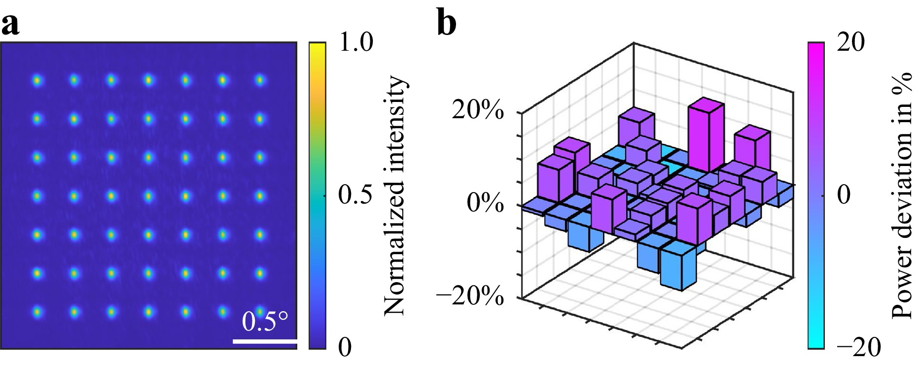
Fig. 5 Optical analysis of the diffractive optical element (DOE) focus array. a false-color plot representing the measured normalized intensity of the DOE focus array. The measurement was performed by positioning a CMOS camera in the back-focal plane and the DOE in the front-focal plane of a 150 mm focal length lens and illuminating the DOE with the laser source (cf. Fig. 2). b calculated power deviation for each individual focus of the DOE focus array. The power was calculated from the fit parameters of a 2D-Gaussian fit that was applied to the intensity profile of each focus and is presented as a deviation from the mean power across the focus array. The height and color of the bars indicate the deviation of each DOE focus from the mean power.
-
By combining the large array of $ 7\times 7=49 $ laser foci with fast scanning speeds of up to $ v=1\;\mathrm{m}/\mathrm{s} $, we now use a high 3D printing rate to produce very large samples or small samples in large quantities while maintaining sub-micron resolution. This opens up the possibility of new studies with previously inaccessible sample requirements. In the following, we demonstrate the capabilities of multi-photon multi-focus 3D printing using an application in the field of respiratory-drug delivery and another application from the field of 3D mechanical metamaterials.
To further customize drug-carrying carrier particles for dry-powder inhalation, sub-micron precision is required28. However, as pharmacists working on next-generation particle engineering require macroscopic powders made up of these small particles, the sheer number of particles required for their experiments quickly exceeds one million. To print individual particles of about 50 μm in size in these numbers, conventional multi-photon 3D laser nanoprinters would require months of printing time. Fortunately, with the setup described above, we can produce 49 carrier particles simultaneously at high speeds, making it possible to produce the above number of particles in a reasonable amount of time. Fig. 6a shows three 2-inch diameter glass wafers onto each of which we have printed approximately 400,000 carrier particles. The printing time per wafer was 8 hours using focus-scan speeds of 1 m/s. The individual particles are printed so close together that they are indistinguishable to the naked eye. We printed three different designs: so-called pharmacones, soccer balls, and rolling knots. Depending on the filling fraction of each design, the polymerized area appears in different colors. The coloration stems from residual photoinitiator molecules in the printed polymer. Fig. 6b−d show scanning-electron micrographs of single particles of each carrier-particle design. We intentionally used slightly coarser hatching and slicing parameters than usual to increase surface roughness, which is intuitively expected to improve drug adhesion to the carrier, offering small grooves to adhere to. However, a detailed optimization of the size, shape, and roughness of such microparticles is well beyond the scope of the present paper. Fig. 6e and Fig. 6f show a larger scene of a substrate with a large number of rolling-knot structures.
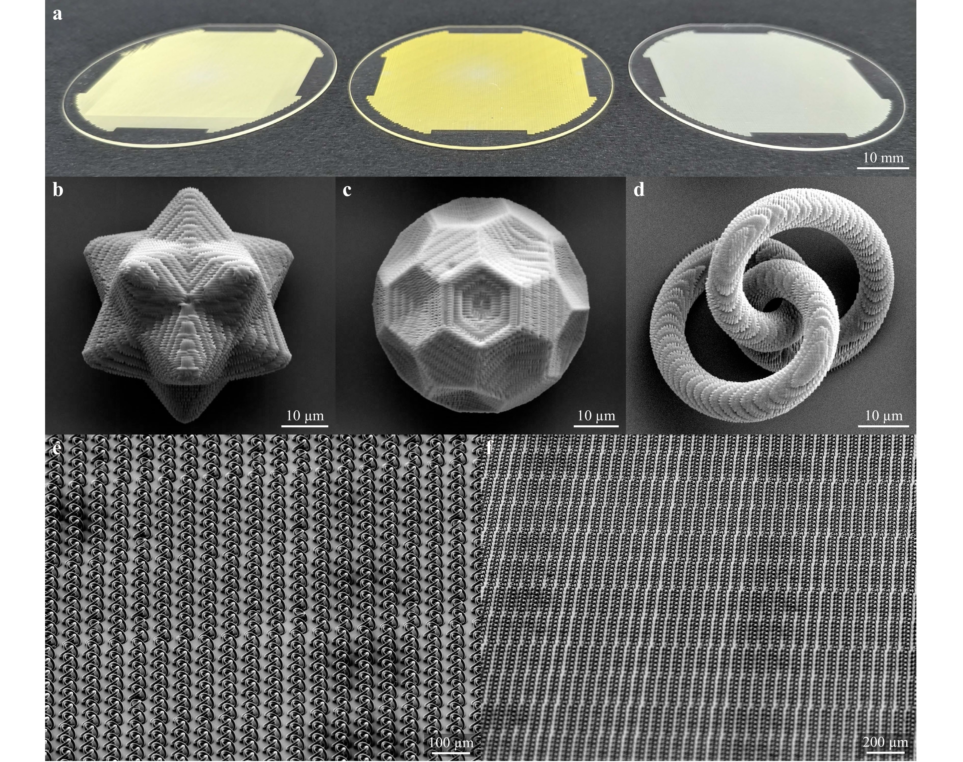
Fig. 6 Manufactured carrier particles for respiratory-drug delivery using multi-photon multi-focus 3D printing. a optical photograph displaying three 2-inch diameter glass wafers with 3D-printed carrier particles of different designs. From left to right, the designs are the so-called pharmacone, soccer ball, and rolling knot, as also shown in panels b-d. Each wafer holds 415,373 carrier particles, which were printed in 8 hours. In total, 18 wafers were made, resulting in the fabrication of approximately 7 million carrier particles in 144 hours. b scanning-electron micrograph showing a single pharmacone carrier particle printed with a specific macroscopic roughness regulated by hatching and slicing to enhance drug adhesion. c scanning-electron micrograph featuring a single soccer ball carrier particle. d scanning-electron micrograph exhibiting a single rolling-knot carrier particle. e scanning-electron micrograph providing an overview of multiple rolling-knot carrier particles printed on the same substrate, with a knot-to-knot center distance of 60 μm. f scanning-electron micrograph showing an expanded view of the same sample, revealing a larger scene of the 3D-printed carrier particles.
To supply this emerging field of research with the required amount of carrier particles, we fabricated structures on $ 3\times 6=18 $ 2-inch diameter glass wafers, resulting in approximately 7 million individual sub-micron-resolved carrier particles. To facilitate easy lift-off of these particles from the substrate, we spin-coated a thin layer of a polyvinyl alcohol (PVA) solution in water onto the wafer. The structures were then fabricated on top of this sacrificial layer, which later dissolves in contact with warm water, allowing the carrier particles on top to fall off the substrate.
Our second application example lies in the field of material science and meets the ever-growing demand for larger and more complex 3D mechanical metamaterial samples with sub-micron resolution. Rather than printing a large number of individual small structures, we print a large sample consisting of individual metamaterial unit cells assembled together. The unit cell design used here has recently been shown to lead to a highly unusual roton-like dispersion relation29. However, fabricating the unit cell containing many overhanging thin rods proved so difficult that the authors had to divide the unit cell print job into more than 50 subsequently printed sub-jobs to ensure that each printed sub-structure was printed on a support. Using focus-scanning velocities as high as v = 1 m/s eliminates this problem because the structure is built-up so fast that there is simply no time for any unsupported part to move away from its desired position. Previously, a focus scanning velocity v = 0.145 m/s was employed29, which is almost 7× slower than the focus-scanning velocity employed in the present work, leaving any overhanging part roughly 7× less time for drifting away from its target position. Fig. 7a shows an optical photograph of a large chiral-roton metamaterial consisting of 77 × 77 × 171 = 1,013,859 unit cells with dimensions of 4.62 × 4.62 × 10.26 mm3, printed in two days of printing time. It contains about 1.7 × 10¹² voxels (voids not counted). A side view of the complete tower is shown in Fig. 7b, revealing the bulk metamaterial block. To demonstrate that this structure is indeed composed of well-defined individual unit cells, Fig. 7c shows an oblique view of the sample taken with a scanning-electron microscope (SEM). Fig. 7d shows a top view of the sample showing a sea of unit cells. A close-up view of a single metamaterial unit cell within the larger structure is depicted in Fig. 7e.
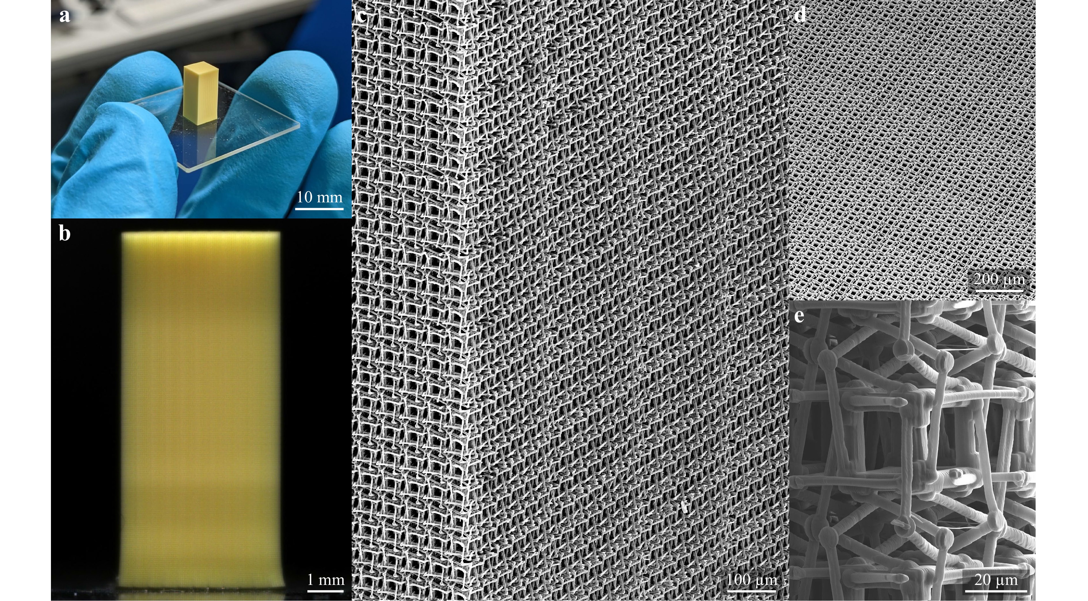
Fig. 7 Multi-photon multi-focus 3D printing of a large chiral-roton metamaterial comprising 77 × 77 × 171 = 1,013,859 unit cells. a optical photograph displaying the 3D-printed metamaterial sample with dimensions of 4.62 × 4.62 × 10.26 mm3 containing more than 1.7 × 10¹² voxels (voids not counted) on a glass substrate. b optical micrograph of the standing metamaterial tower. c scanning-electron micrograph presenting an oblique view of the manufactured chiral-roton metamaterial. d scanning-electron micrograph showing the top view of the metamaterial tower. e close-up scanning-electron micrograph focusing on a single chiral-roton metamaterial unit cell.
-
To put the manufacturing speed of our new setup into perspective, we compare various 3D printing technologies as first published in Ref. 13 in Fig. 8. The vertical axis ranks the different approaches in terms of their total peak printing rate (on a logarithmic scale), whereas the horizontal axis ranks them in terms of their inverse voxel size or, loosely speaking, their fineness or resolution (again on a logarithmic scale). Notably, the peak printing rate does not include any sources contributing to overhead times such as, e.g., stage movements, during printing. Data based on two-photon (or multi-photon) polymerization are shown in red in this representation.
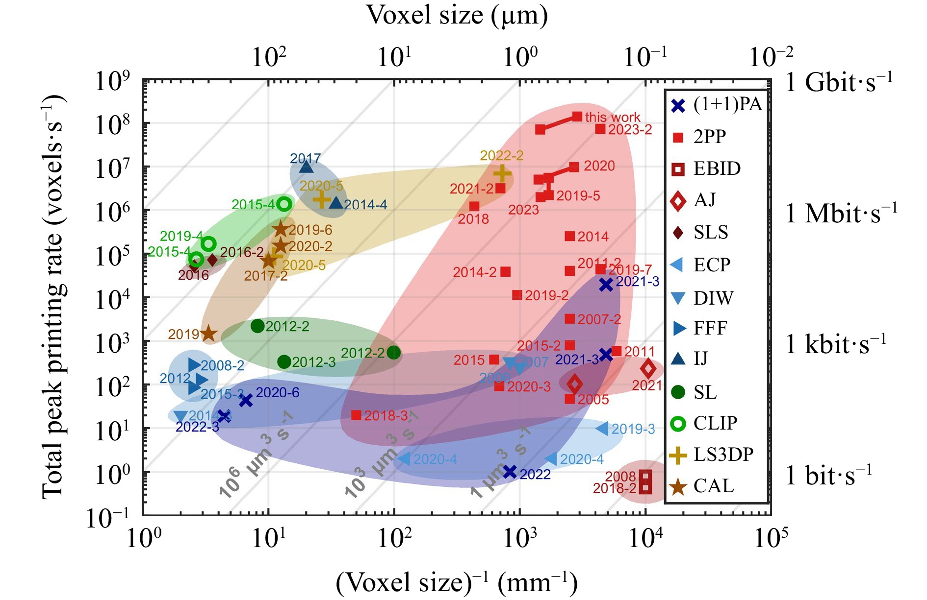
Fig. 8 Comparison of different 3D printing technologies based on their peak printing rate and voxel size. The next-generation multi-photon multi-focus 3D printing version presented in this paper surpasses the printing speed threshold of 108 voxels/s with a calculated diffraction-limited voxel size of approximately 350 nm. The additional data point connected to it corresponds to the same setup but uses an average measured voxel size across the array of 7 × 7 = 49 foci. The legend includes various technologies such as two-step absorption ((1+1)PA), two-photon printing (2PP), electron-beam-induced deposition (EBID), aerosol-jet 3D nanoprinting (AJ), selective laser sintering (SLS), electrochemical printing (ECP), direct ink writing (DIW), fused filament fabrication (FFF), inkjet printing (IJ), stereolithography (SL), continuous liquid interface printing (CLIP), light-sheet 3D printing (LS3DP), and computed axial lithography (CAL). The labels connect to the references 200518, 200631, 200732, 2007-212, 200833, 2008-234, 201135, 2011-214, 201236, 2012-237–39 (with data points from Ref. 40), 2012-341, 201442, 2014-243, 2014-344, 2014-445, 201515, 2015-216, 2015-346, 2015-447, 201648, 2016-249, 201750, 2017-240, 201851, 2018-252, 2018-353, 201954, 2019-255, 2019-356, 2019-457, 2019-558,59, 2019-660, 2019-761, 202013, 2020-262, 2020-311, 2020-463, 2020-564, 2020-665, 202166, 2021-267, 2021-368, 202269, 2022-270, 2022-371, 202372, 2023-230, and this work. This figure has been adapted from the original version from Ref. 13 and the updated version from Ref. 70 and is available under the CC BY 4.0 license. A regularly updated version of this illustration can be accessed on https://3dprintingspeed.com.
Our previous version of multi-photon multi-focus 3D printing with the label “2020” was able to achieve peak printing rates of approximately 107 voxels/s13. By increasing the number of foci from 9 to 49 and additionally enhancing the available maximum focus-scanning speed by a factor of two, we arrive at a peak printing rate of 1.4 × 10⁸ voxels/s for our next-generation setup, which can be found under the label “this work”. The setup is represented by using two data points: One assuming a diffraction-limited voxel size of approximately 350 nm (see introduction), and the same result using an averaged measured voxel size within the 7 × 7 focus array (cf. Figure S1) yielding 7.1 × 10⁷ voxels/s. Our results are in the same league as recently published advances using acousto-optical deflectors in combination with a digital mirror device (DMD) with the label “2023-2”30, also based on two-photon polymerization for fast 3D printing. Compared with their work, we demonstrate much larger printed structures in terms of total number of voxels in one structure. This is partly due to the much larger accessible FOV in our work.
-
The field of rapid 3D laser printing based on two-photon polymerization has long recognized that some degree of parallelization is necessary to further increase manufacturing speed. However, all approaches facilitating parallelized 3D laser printing have suffered from and worked around fundamental problems associated with these parallelization techniques.
By addressing one of the major challenges of diffractive beam splitting for femtosecond-pulsed lasers and solving it with a new approach combining a diffractive optical element (DOE) with a multi-lens array (MLA), we have designed and built a new setup for multi-photon multi-focus 3D printing that does not suffer from angular dispersion. This advance not only allows for a larger number of laser foci at even higher scan speeds, but also for large fields of view (FOV), which are still limited for other recent fast approaches in the field30. Furthermore, by simulating, developing, building, and using low-aberration optical lens systems, we have been able to utilize the large available FOV without strong aberrations at the edges of the focus array. The use of this setup for two selected current applications, one in pharmacy and one in materials science, provides scientists with sample numbers and dimensions that have previously been inaccessible, enabled by a total peak printing rate of about $ {10}^{8}\;\mathrm{v}\mathrm{o}\mathrm{x}\mathrm{e}\mathrm{l}\mathrm{s}/\mathrm{s} $.
Two aspects, (i) and (ii), presently limit yet higher total peak print rates. (i) More laser foci to increase throughput at fixed FOV is only possible by decreasing the distance between neighboring foci. This step further limits the complexity of individual structures that can be printed with the array. Furthermore, if neighboring foci are brought very close together, interference among them will eventually distort the previously homogeneous intensity distribution within the array73,74. At large numerical aperture (NA) and large magnifications, microscope objective lenses with larger FOV are presently not available. One avenue could be the use of objective lenses with larger FOV at lower NA. However, this step would deteriorate the accessible spatial resolution and lower peak intensities. This may be acceptable for certain applications though. (ii) For a given photoresist and at otherwise fixed printing conditions, increasing the number of foci simply proportionally increases the required laser power. In this work, we have already sent about 1 W of average femtosecond-laser power through the immersion microscope objective lens over timespans of many hours. Substantially larger laser powers are expected to damage currently available immersion-mode microscope objective lenses. Therefore, to further increase the total peak printing rate without having to go to larger laser powers, yet more sensitive multi-photon photoresists at optimal laser center wavelengths75 compatible with high focus-scanning speeds are very highly desirable9.
-
The DOE and MLA samples have been manufactured using a Quantum X lithography system (Nanoscribe GmbH). We used the 2GL mode with default parameters comprising a slicing distance of 1 μm and a hatching distance of 200 nm for the DOE and a slicing distance of 1 μm and a hatching distance of 100 nm for the MLA.
-
To anti-reflection coat the micro-optical components with a 120 nm thick layer of Al2O3 and a 140 nm thick layer of MgF2, we used an e-vap CVS-6 device (MDC). The Al2O3 and MgF2 layers were deposited using evaporation rates of $1.5\;{\text Å}/{\rm s} $ and $5.0\;{\text Å}/{\rm s} $, respectively.
-
The employed photoresist in our multi-photon multi-focus 3D printing consists of the monomer mixture IP-DIP NPI with 0.5 wt% BBK ((2E,6E)-2,6-Bis(4-(dibuthylamino)benzylidene)-4-methylcyclohexanone) mixed into it. IP-DIP NPI was purchased from Nanoscribe while BBK was synthesized for us by chemist Maximilian Bojanowski at KIT. The mixture is stirred on a hot plate at a temperature of 35°C for 12 hours until the photoinitiator has dissolved. Properties of BBK as well as its synthesis is published in Ref. 9.
-
All samples with carrier particles printed onto them have been developed by successively immersing them for 2 × 10 min in PGMEA (propylene glycol methyl ether acetate) and 2 × 5 min in IPA (isopropanol). Afterwards, the sample was dried by placing it in a fume hood.
The chiral-roton metamaterial sample was developed like described above, however, instead of drying it in a fume hood, it was supercritically dried in CO2 (EM CPD300, Leica Microsystems).
-
The sacrificial layer to print large amounts of carrier particles on is based on a solution containing 7 wt% PVA (polyvinyl alcohol) dissolved in water. The mixture was stirred on a hot plate at a temperature of 80°C for 24 h until all PVA had dissolved. Creating the sacrificial layer was afterwards achieved by spin coating (KL-SCE-150, Quantum Design GmbH). The solution was applied on the substrate which was afterwards rotated with 67 rps for 60 s. Finally, the sample was baked on a hot plate at a temperature of 80°C for 2 min.
-
To achieve a macroscopic surface roughness of the carrier particles, we chose a slicing distance of 400 nm and a hatching distance of 300 nm. The chiral-roton metamaterial sample was printed with a slicing distance of 300 nm and a hatching distance of 200 nm.
-
Measuring the sample topography of the DOE and MLA samples has been performed by using an optical spinning-disc confocal microscope (MarSurf CM explorer S/W, Mahr GmbH). The multi-focus printed samples have been imaged using a digital microscope (Smartzoom 5, Zeiss) and a scanning-electron microscope (Supra 55VP, Zeiss). The multi-focus printed suspended voxel lines for the voxel size characterization have been imaged using a through-lens detector of a focused-ion-beam scanning-electron microscope (Strata 400S dual-beam system, FEI).
-
The authors thank Maximilian Bojanowski (KIT) for the synthesis of the photoinitiator BBK and Paul Somers (KIT) for carefully proofreading this manuscript. We acknowledge funding by the Deutsche Forschungsgemeinschaft (DFG, German Research Foundation) under Germany’s Excellence Strategy for the Excellence Cluster “3D Matter Made to Order” (2082/1–390761711), by the Carl Zeiss Foundation, and by the Helmholtz program Materials Systems Engineering.
A multi-photon (7 × 7)-focus 3D laser printer based on a 3D-printed diffractive optical element and a 3D-printed multi-lens array
-
Pascal Kiefer1, 2, *, ,
 ,
, - Vincent Hahn1, 2, 3,
- Sebastian Kalt1, 2,
- Qing Sun1, 4,
- Yolita M. Eggeler1, 4,
- Martin Wegener1, 2, 3
- Light: Advanced Manufacturing 5, Article number: (2024)
- Received: 03 August 2023
- Revised: 02 December 2023
- Accepted: 18 December 2023 Published online: 06 March 2024
doi: https://doi.org/10.37188/lam.2024.003
Abstract: One of the challenges in the field of multi-photon 3D laser printing lies in further increasing the print speed in terms of voxels/s. Here, we present a setup based on a 7 × 7 focus array (rather than 3 × 3 in our previous work) and using a focus velocity of about 1 m/s (rather than 0.5 m/s in our previous work) at the diffraction limit (40×/NA1.4 microscope objective lens). Combined, this advance leads to a ten times increased print speed of about 108 voxels/s. We demonstrate polymer printing of a chiral metamaterial containing more than 1.7 × 10¹² voxels as well as millions of printed microparticles for potential pharmaceutical applications. The critical high-quality micro-optical components of the setup, namely a diffractive optical element generating the 7 × 7 beamlets and a 7 × 7 lens array, are manufactured by using a commercial two-photon grayscale 3D laser printer.
Research Summary
New Generation of Multi-Focus 3D Laser Printing Allows for New Sample Dimensions
A new setup for highly-parallelized multi-focus 3D laser printing allows for print rates of 100 million voxels per second. This technology leap is based on a novel hybrid approach for efficient beam splitting using a diffractive optical element and a lens array for generating ![]() individual laser foci. Both elements have been manufactured by commercial two-photon grayscale lithography. The new capabilities are demonstrated by 3D printing a chiral metamaterial with more than 1 trillion voxels and millions of microparticles for potential pharmaceutical applications.
individual laser foci. Both elements have been manufactured by commercial two-photon grayscale lithography. The new capabilities are demonstrated by 3D printing a chiral metamaterial with more than 1 trillion voxels and millions of microparticles for potential pharmaceutical applications.
Rights and permissions
Open Access This article is licensed under a Creative Commons Attribution 4.0 International License, which permits use, sharing, adaptation, distribution and reproduction in any medium or format, as long as you give appropriate credit to the original author(s) and the source, provide a link to the Creative Commons license, and indicate if changes were made. The images or other third party material in this article are included in the article′s Creative Commons license, unless indicated otherwise in a credit line to the material. If material is not included in the article′s Creative Commons license and your intended use is not permitted by statutory regulation or exceeds the permitted use, you will need to obtain permission directly from the copyright holder. To view a copy of this license, visit http://creativecommons.org/licenses/by/4.0/.

 DownLoad: