


-
Since the invention of the photographic camera in the early 19th century, the art of lens design has undergone many developments. First designs were based on simple lenses which were designed by trial and error and suffered from chromatic aberrations, field curvature and other aberrations. Due to requirements towards smaller F-number or high NA (photography driven by exposure time; microscopy driven by resolution) and to achieve the simultaneous correction of all aberration types, the design task becomes increasingly challenging and requires a systematic optimization approach. To cover the basic aberrations methods like Seidel theory have been developed. Higher order aberrations can be calculate by ray tracing. In the early days these time-consuming calculations were performed by humans1, but as soon as computers became available, dedicated software was implemented to perform these costly calculations2–6. Until this day all of these optical design software have in common, that the table the lens data is stored in basically still represents the list of surfaces used to manually calculate the rays path7–9. The rays are always sequentially traced from the first to the last surface in the list, which means that the list not only contains the system prescription data, such as radius of curvature or materials, but also implicitly defines the ray tracing path through the lens. However, since the early days the requirements for optical design software have drastically changed. While in classical designs mainly spherical and rotationally symmetric aspherical surfaces were used, modern optical designs utilize a wide range of surface shapes and types ranging from free-form surfaces to lens arrays or diffraction structures on curved substrates. Furthermore, optical systems are often folded to achieve a more compact and lightweight design. Moreover, many systems — particularly in the area of metrology — require more than one path of light propagating through the system, or contain double passes through parts of the lenses. While most optical design software is capable of dealing with these challenges, the solution is typically some sort of workaround and leads to models that are hard to setup, understand and maintain. In this paper we propose a new approach on how to define lens data as well as ray tracing settings inside an optical design software, which is also used in our software package10. The approach introduces a new type of data structure that provides an additional layer of abstraction in between the users lens data and the data used by the ray tracing algorithm offering numerous advantages throughout the design process.
-
In classical sequential optical design software, the optical system is typically defined by a data structure that organizes as a list of surfaces. The first surface in the list represents the object surface from where the rays start. The object surface is followed by a number of optical surfaces that define the description of the lens. For example, a singlet lens is represented by two spherical surfaces, where the material of the lens is defined by the material of the first surface and the thickness of the lens by the thickness of the first surface. The material of the second surface is air to represent the air space in between the lens and the next surface and the thickness of the second surface defines the distance in between the lenses. The last surface in the list is the image surface. This structure is basically a one-to-one representation of the calculation steps one would need to perform to trace a ray through the system surface by surface (see Fig. 1)
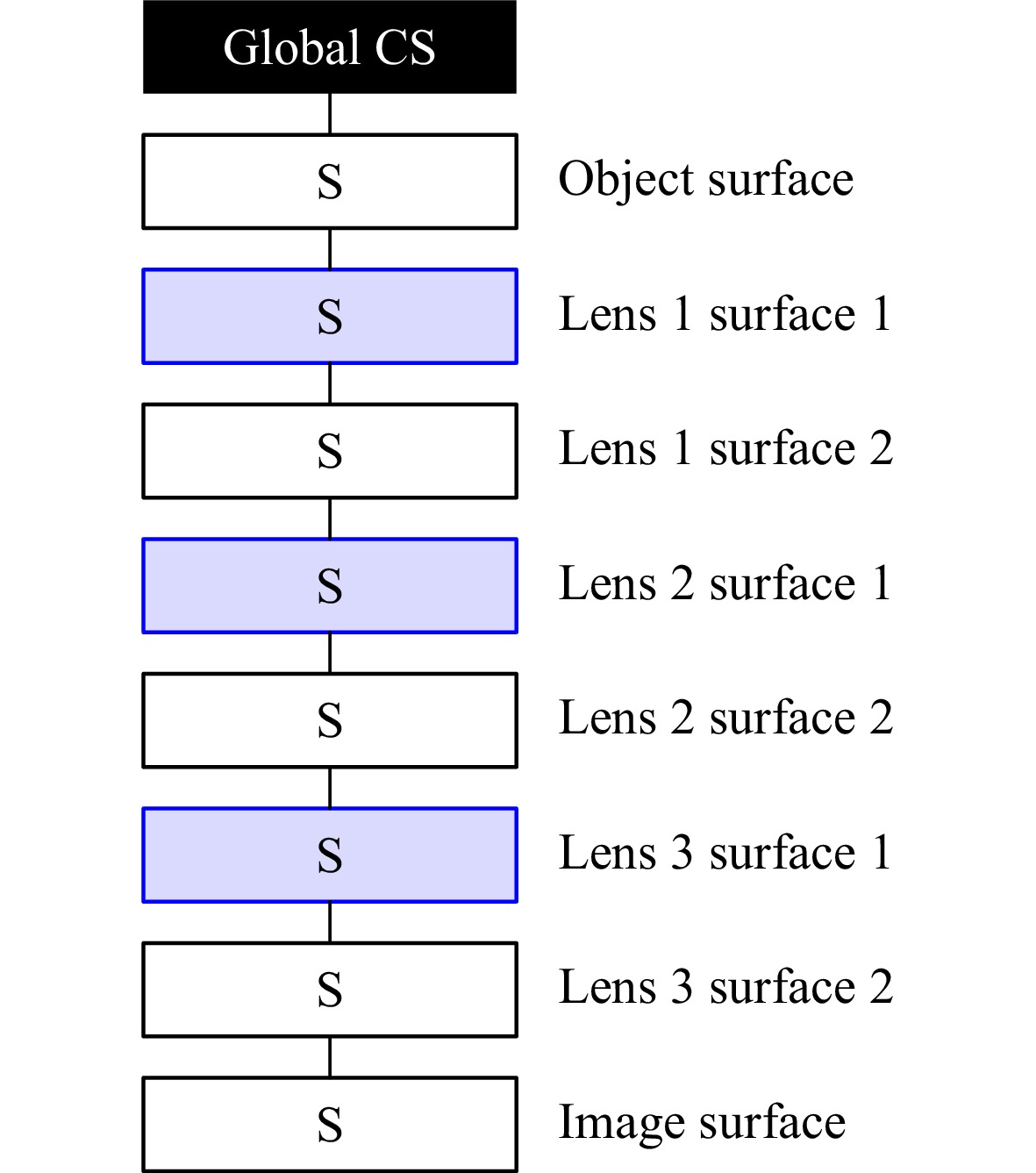
Fig. 1 List based surface data structure. The first surface is fixed in the global coordinate system (Global CS). All subsequent surfaces (S) are positioned relative to the previous surface. The example shows the data structure for a lens design consisting of three singlet lenses with air spaces in between.
For the design of classical lenses as on-axis camera objectives the list-based representation is well suited. However, the disadvantage of the list-based data structure can already be clearly seen in the ghost or tolerance analysis. Furthermore, the requirements for high-end optical systems have shifted away from simple spherical on-axis systems to aspherical or free-from lenses, off-axis systems or systems where more than one sequence is of interest. In detail, these challenges are the following.
-
A multi-pass system is an optical system where the light passes through one or more lenses, reflects on a surface and goes back through the lens or lenses again. An application that requires such a multi-pass would e.g., be a confocal microscope, where the probe is illuminated through the objective and then the light is reflected back into the same objective. Another application is the simulation of ghost reflections at optical surfaces, where the light is reflected at one or more optical surfaces inside the lens and forms a — typically unwanted — ghost image on the image plane. The problem with both applications is, that in order to perform sequential ray tracing of such models, it is required to define all the involved surfaces multiple times in the surface list. In case of the ghost model, it is even necessary to define a large number of such lists — one for each possible ghost sequence — to be able to simulate the combined irradiance at the image surface.
-
As already pointed out, ghost analysis often requires to defining multiple sequences of surfaces for the ray tracing. Another obvious example for such a system would be an interferometer, where the light is split into two paths, a test path and a reference path. The issue with such systems is, that the surface list can only define a single sequential path. The workaround for this problem is typically to either define each path in an individual model file — which has the disadvantage that, e.g., in the case of the interferometer, it is not possible to interfere the light, because each model only contains one part — or to define multiple configurations for the system, where in each configuration the other part of the sequence is ignored and all surfaces get skipped.
-
Each single line in the surface list defines a single surface of the optical system. To be able to describe the wide range of possible optical surfaces such as aspheric or free-form surfaces, diffractive optics, holograms, polarization optics or gradient index lenses, each surface can have a surface type that defines which parameters are available and according to which physical model it behaves. This works fine as long as the exact surfaces are available as a surface type. However, a flexible configuration of a surface is not possible. Especially when it comes to tolerance analysis, it is often desired to simulate fabrication artifacts as local, periodic or random surface deviations of different shapes, to load measurement data to verify the optical performance of a system with as-build tolerances, or to add phase deviations to a diffractive grating. It would require an almost infinite amount of surface types to simulate all possible cases that might be required for a certain simulation.
-
The positioning of surfaces in a list-based data structure is achieved by assigning a thickness to each surface. This means that the next surface is always positioned relative to the previous surface, with the thickness parameter describing the distance in z-direction. This approach works well for classical on-axis systems. However, in order to simulate off-axis or folded systems, it is required to introduce dummy surfaces, that are not real surfaces, but act as a mathematical operator that manipulates the coordinate system by shifting and/or tilting the following surfaces. This approach allows to position surfaces in any position or orientation, but it has several disadvantages.
- For instance, when a single element or a group of elements needs to be tilted or decentered - which is often necessary during tolerance analysis - it is required to undo the coordinate system change after the tilted element or group.
- The coordinates of a surface are always relative to the previous surface, which is not ideal for tolerance analysis. To achieve an absolute positioning of the surface, or to position the surface relative to another reference (e.g. the local assembly coordinate system) some sort of workaround is required, for which even more dummy surfaces have to be placed.
- Rotating a surface not about the optical axis but an off-axis pivot point requires multiple dummy surfaces.
- If the system includes multiple passes through a lens in addition to off-axis surfaces, or multiple sequences are required for the overall design, it can get extremely complicated to keep track of all the coordinate systems, in particular concerning the order of rotations to be applied.
In summary, all these scenarios often lead to convoluted models that are hard to understand and maintain.
-
The challenges discussed in the previous section section do not arise from a fundamental property of these systems, but emerge from an incomplete data structure that does not contain any information about the mechanical dependencies of the surfaces, as well as from the mixing of optical properties of the lens with settings for the ray tracing to be performed. The method we propose to overcome all these challenges is to add an additional layer of abstraction on top of the data structure, and to separate the lens geometry and optical parameter information from the ray tracing information into two separate data structures.
-
As mentioned in the previous section, in a classical list-based data structure, multi-pass systems as well as multi-sequential systems can only be achieved through workarounds which requires to define exactly the same surface several times. The reason for this is that the data structure holds both, the information about the geometry and the optical properties of the surfaces, as well as — implicitly — the sequential path information for the rays to be traced. This results from the fact that the ray tracing path is always directed from the first to the last surface in the list and cannot be changed. A simple solution to solve this problem is to separate the data into two data structures.
- The first data structure defines the lens design. In principle, this could also simply be a list of surfaces, however — unlike in a classical list — the order of the optical elements in the list is no longer of importance.
- The second data structure defines the sequence of the surfaces for the ray tracing. The difference between this surface list and a classical surface list is that each entry only refers to a surface in the lens design data structure, but does not hold any information about the optical properties, the shape or the position of the surface. The only property that is defined in the sequence list is the type of interaction to be evaluated at each surface. This could be, e.g., a transmission, reflection or different diffraction orders at a phase surface.
Splitting the information into two separate data structures directly allows to create double-pass systems without the need to define surfaces multiple times. Even with off-axis systems, complicated coordinate system manipulations on the backward path, which often can lead to errors in a double pass system, are no longer needed. The ability to define an arbitrary amount of sequential paths furthermore directly allows the definition of systems like interferometers where more than one optical path is of interest, or to perform ghost analysis on a lens. One possible option for the simulation of such systems is to rely on non-sequential ray tracing. In non-sequential ray tracing, the path of a ray through the system is not predefined, but is chosen during the simulation by a random chance for a transmission, reflection or scattering occurring at each surface.
However in comparison to non-sequential ray tracing multi-sequential ray tracing comes with several advantages.
- Sequential ray tracing is a lot faster than non-sequential ray tracing. This is because the information which surface needs to be traced next is already available before the ray tracing begins. This eliminates the need to search the surface list for the surface that is hit next and also makes it possible to compute data that is common to all rays prior to the actual ray tracing.
- All ray traces can be performed on the same data structure which avoids overhead and conversion losses when exporting or converting a sequential design to a model that is suitable for non-sequential ray tracing for the purpose of ghost analysis.
-
Regarding the coordinate systems our approach aims to solve two problems. First, the aim is to get rid of dummy surfaces and complicated procedures that are required to undo a coordinate system change or to define the pivot point. The second aim is to obtain a method that can be used to define complex off-axis and folded systems, but that can also be used for tolerance analysis, while still being easy to understand and maintain. This is especially important if the coordinate changes are auto-generated by the tolerancer’s Monte Carlo algorithm and complex dependencies of assemblies and sub-assemblies need to be modeled. Our proposed solution to this problem is to replace the surface list with a hierarchical tree-like data structure in combination with higher level elements as lenses, prisms or assemblies (see Fig. 2)
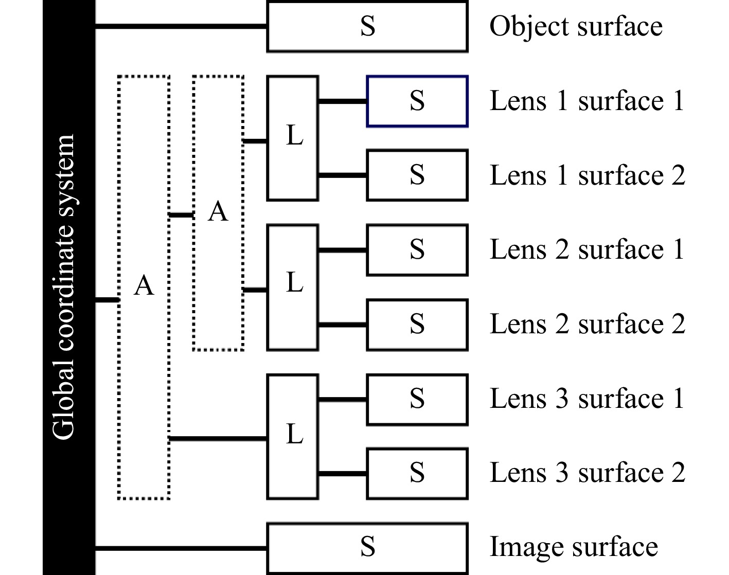
Fig. 2 Nested coordinate systems in tree-like structure with each branch defining a new local coordinate system. A represents an assembly of lenses, or sub-assemblies, L represents a lens and S represents the surfaces of the leafs of the tree-like structure. The example describes the same lens consisting of three singlets as in Fig. 1. In contrast to the list-based data structure, not only the optical properties but also the mechanical dependencies of the surfaces are contained in the data structure.
The fundamental concept is to define positional dependencies in the same manner as they exist in the real optical system, in to how they are defined in a mechanical CAD software.
To see how this works, let us consider an assembly consisting of two lenses. The overlaying assembly defines a local coordinate system in which both lenses can be positioned. Since both lenses are defined inside the assembly coordinate system, changing the assembly position automatically moves both lenses. At the next hierarchical level the method is basically the same. The lens element — as an assembly — defines a local coordinate system in which the surfaces that belong to the lens are defined. Again this makes it easy to position a lens in 3D space without affecting the surface positions inside the lens coordinate system. A second improvement we implemented is the ability to have several options for positioning elements. The first option is relative to the previous surface, which comes closest to the classical approach where surface thicknesses are defined. The second option is to position an element or assembly in absolute coordinates inside the local coordinate space defined by the overlying assembly. This allows to, e.g., move a lens while the following lens position remains unchanged. Furthermore, the pivot point for each coordinate system can be freely defined, giving the designer even more flexibility. In addition, even more advanced coordinate dependencies can be added — e.g. for tolerancing of barrel mounts where a thickness tolerance of a lens in the stack moves the next lens along the z-axis but a tilt of the previous lens does not automatically tilt the following lens with it. One additional benefit that results directly from this data architecture is the ability to define volume properties inside the element coordinate system. Considering, for example, an optical element made of a birefringent material, a gradient index profile (GRIN) lens or any other volumetric optical element. In a surface list-based model the coordinate system in which a material is defined is always the surface prior to it. This means that, e.g. tilting the surface will also change the coordinate system along which the ordinary/extraordinary axis or the GRIN profile is defined, which typically is not desired and may lead to problems during tolerance analysis.
-
The solution to drastically increase the flexibility of the available surface definitions we propose is again a change from a list-based to a tree-like data structure. Instead of providing a certain selection of available surface types, the only surface type needed is a basic spherical surface with a circular aperture. For classical spherical optics, the surfaces can directly be used without additional modifications. For any other surface type, the surface can be freely configured based on a modular approach by adding an arbitrary range of surface properties to it. To define an aspherical surface, an aspherical form property can be added to the base surface. To define an aspherical surface including tolerances from the polishing, in addition to the aspheric form property, a Zernike form property, a grid-sag-interpolation form property, a local surface deviation defined by Gaussian function and many other options or all together can be added. Furthermore, it is possible to directly import form deviations, e.g. from common interferometer data formats. The local surface sag is computed as the sum of the sag functions defining the surface (see Fig. 3).
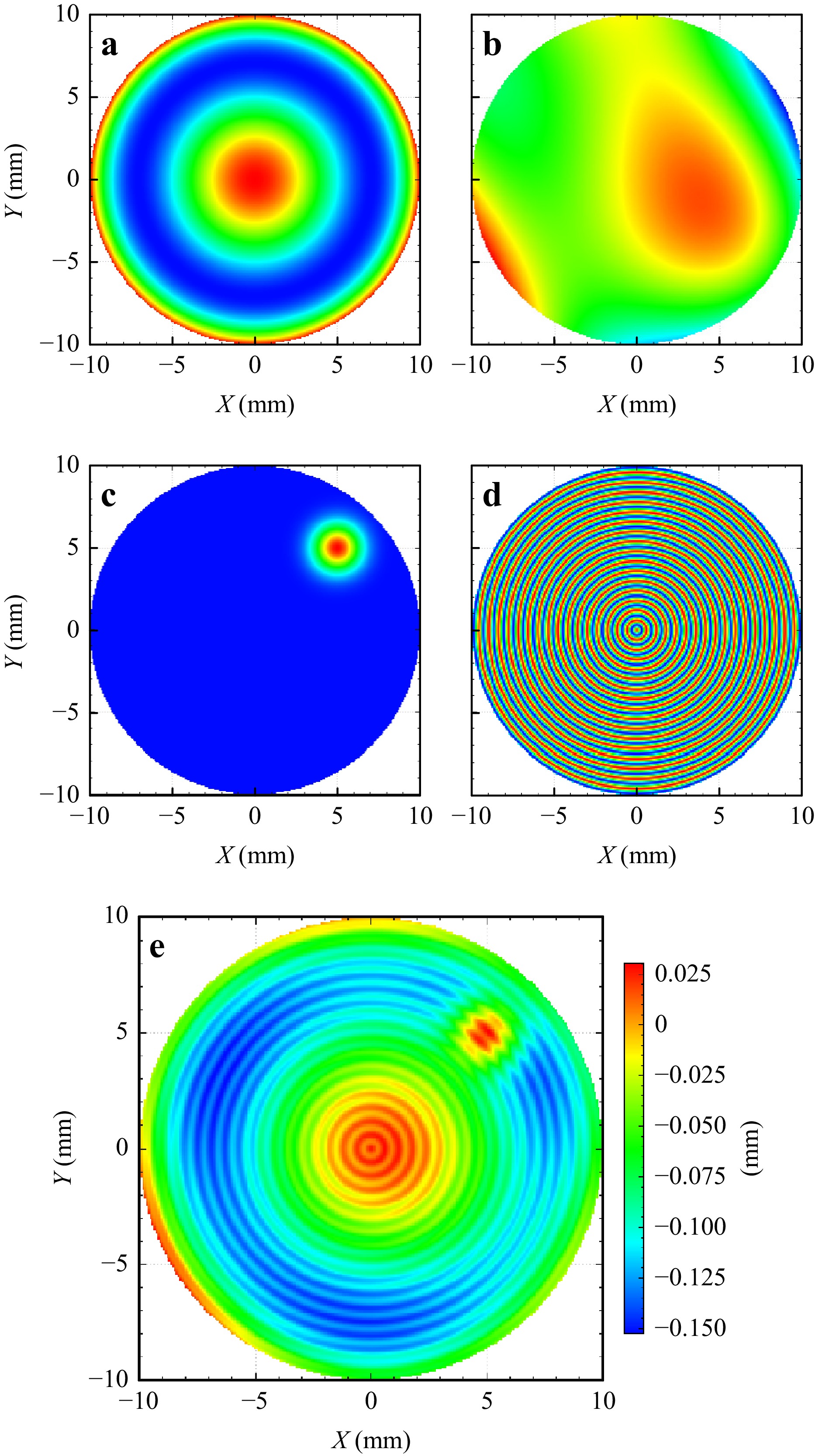
Fig. 3 Surface Stack built from the sum of several base surface sag functions a base asphere; b Zernike error c Local surface error; d Mid spatial frequency error; e Final combined surface shape.
The same method can be applied to phase functions, apertures, coatings, polarization properties or any other surface property. Overall, this approach allows to define an almost infinite variety of possible surface types.
-
To demonstrate the capabilities of the approach we take a single lens cats-eye retro reflector as a first example (see Fig. 4).
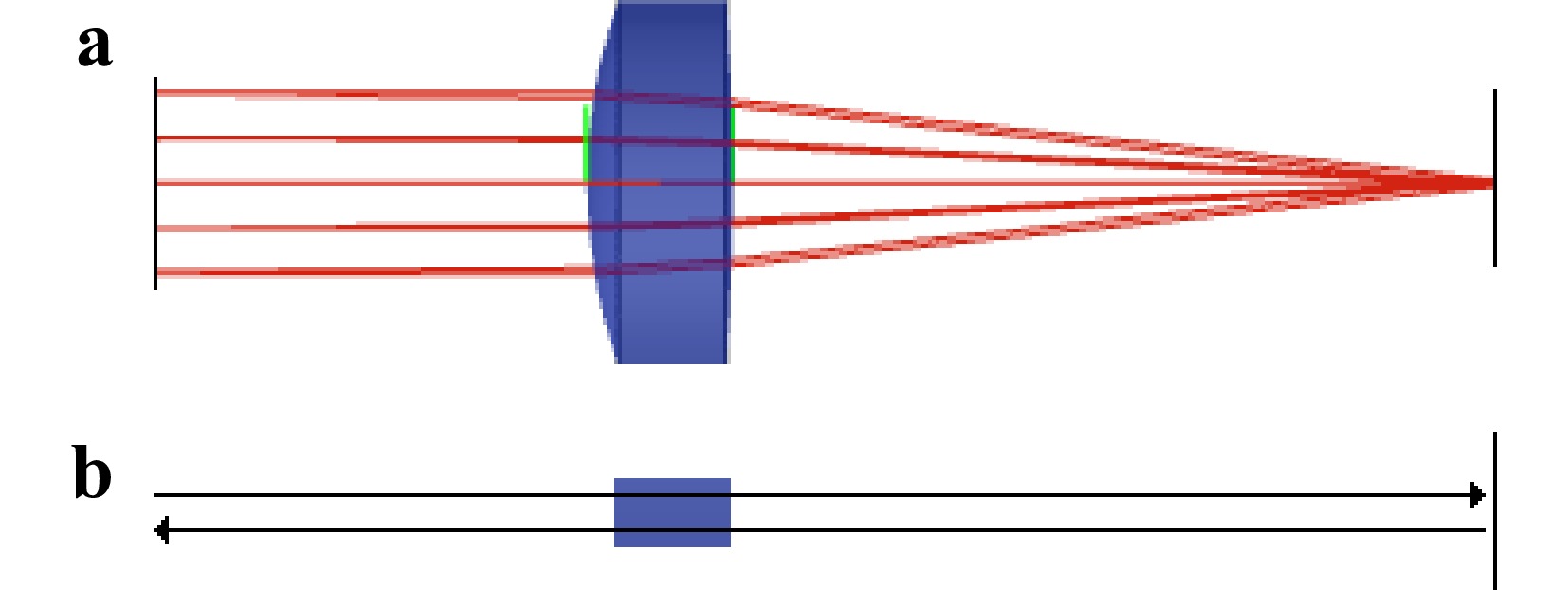
Fig. 4 Cats-eye retro reflector a Layout of the system; b Ray tracing path: The rays start collimated at the left, then are transmitted through the lens and reflect off the mirror surface to the right, then pass the lens a second time and propagate back to the start surface.
The collimated rays enter the lens which focuses them onto the mirror. The rays are reflected back from the mirror, pass through the lens a second time where they are collimated before propagating back to the source. Since the rays pass the lens two times, in a classical list based model we need to model each of the two surfaces of the lens twice, whereas in our model this is not necessary (see Fig. 5).
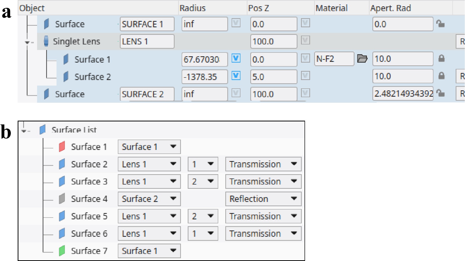
Fig. 5 Tree model of cats-eye retro reflector a Optical model of the system. The tree structure defines the positions and optical properties of the lens and mirror surface incl. The radius of curvature, materials as in a classical list based editor b Sequence definition for the ray trace. The model contains the path definition and refers to the surfaces defined in the optical model. In this double path system the two surfaces of the lens are both referred twice.
The second example is a camera lens on which a ghost reflex analysis is performed (see Fig. 6). Such a task would typically be carried out in a non-sequential ray tracing software. The drawback when relying on a second software is, that in the process of the conversion to the non-sequential model information can be lost. Furthermore, non-sequential ray tracing is a lot slower compared to sequential ray tracing. Our approach allows to perform the ghost analysis directly within the same model, by manually defining ghost paths or by automatically generating a sequence for every possible first or second order ghost. Another speed advantage comes from the prior knowledge that after three or more reflections at coated surfaces typically no relevant intensity is left, so these sequences can directly be ignored, whereas in non-sequential ray tracing these paths may get explored and then dropped leading to unnecessary computational overhead.
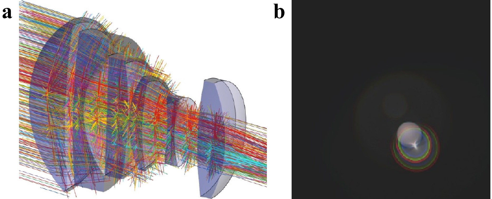
Fig. 6 Ghost image analysis of a camera lens a Visualization of a polarization ray trace of the 10 ghost sequences with the highest intensity in image space. Each ray color represents a different ghost path b Intensity image formed in the image plane, calculated by integrating over all ghost sequences and three color channels. For the calculation of the final intensity distribution coating-stacks, polarization as well as bulk absorption is considered.
The third example is a beam splitter cube (BS) in a classical Twyman-Green-interferometer configuration. The rays enter the BS from the left and are split into a test and a reference beam. The test beam exits the BS to the right, gets reflected at the test surface and propagates back into the BS, where it gets reflected at the beam splitting surface and propagates further to the detector plane. The reference beam enters the BS from the left and gets reflected at the splitting surface. It exits the BS at the bottom and reflects from the reference mirror. On the second pass, the beam is transmitted straight through the beam splitter up to the detector plane, where it interferes with the test beam (see Fig. 7).
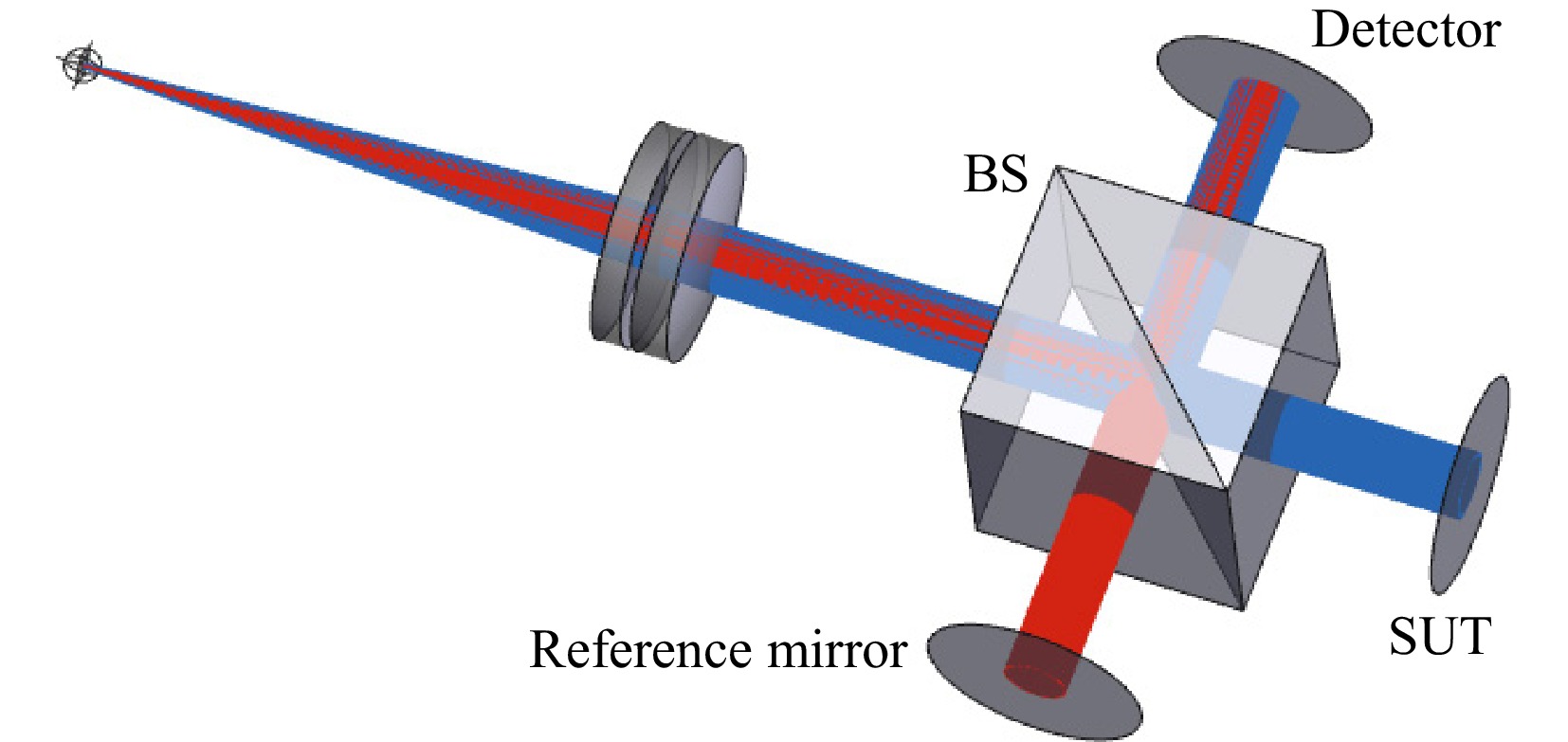
Fig. 7 Twyman-Green interferometer setup: The interferometer consists of a collimation lens, a BS cube, two mirrors and a detector plane. The blue rays indicate the test path. The rays are reflected at the surface under test (SUT). The red rays indicate the reference path. The rays are reflected at the reference mirror.
In a classical list-based approach to model such a system, the best option would be to define two configurations — one for the test beam and one for the reference beam. For each configuration — if the path is folded for a given sequence — dummy surfaces to change the coordinate system need to be placed. Since in both arms the BS is passed twice it needs to be modeled twice for each configuration. In summary, the splitting surface needs to be modeled four times, and the other four optical surfaces of the cube need to be modeled twice. (see Fig. 8)
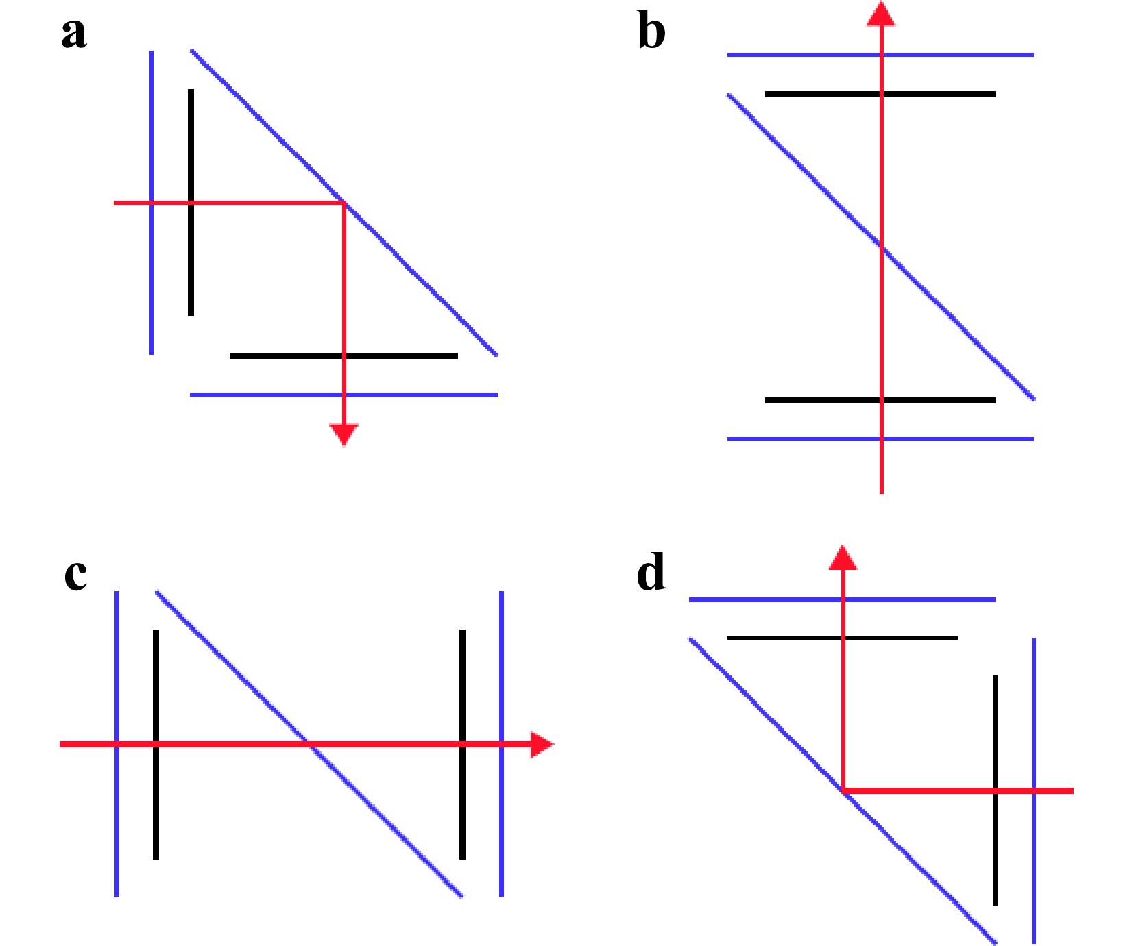
Fig. 8 Schematic of the surfaces that need to be modeled in a classical list based approach: The blue lines represent optical surfaces, black lines represent dummy surfaces to apply coordinate system changes. The top two passes a and b are setup within the first configuration and are part of the reference beam path. The bottom two passes c and d are part of the second configuration and the test beam path.
To perform a tolerance analysis in order to estimate the impact of a rotation of the BS around a common pivot point, it would be required to add 16 dummy surfaces to apply the rotation for all four passes through the BS. This leads to a total of 12 optical surfaces plus 8 dummy surfaces in order to model the BS plus 16 additional dummy surfaces in order to simulate a tilt tolerance. In summary, this means that with a list based model two configurations and 36 surfaces are necessary to model a simple beam splitter cube that consists of five optical surfaces. Such a system is therefore very time consuming to set up and also complicated to maintain and to debug.
In contrast to this, in our object-based model, no multiple configurations and only the five optical surfaces are needed to model the BS. All surfaces are placed within the BS element coordinate system (see Fig. 9). Even to apply a tilt tolerance, no additional dummy surfaces are required, since changing the rotation of the BS element, automatically rotates all the surfaces that are defined within the local element coordinate system. Since the pivot point of the element can freely be adjusted, it is furthermore possible to rotate the cube around an arbitrary point, without any additional effort.
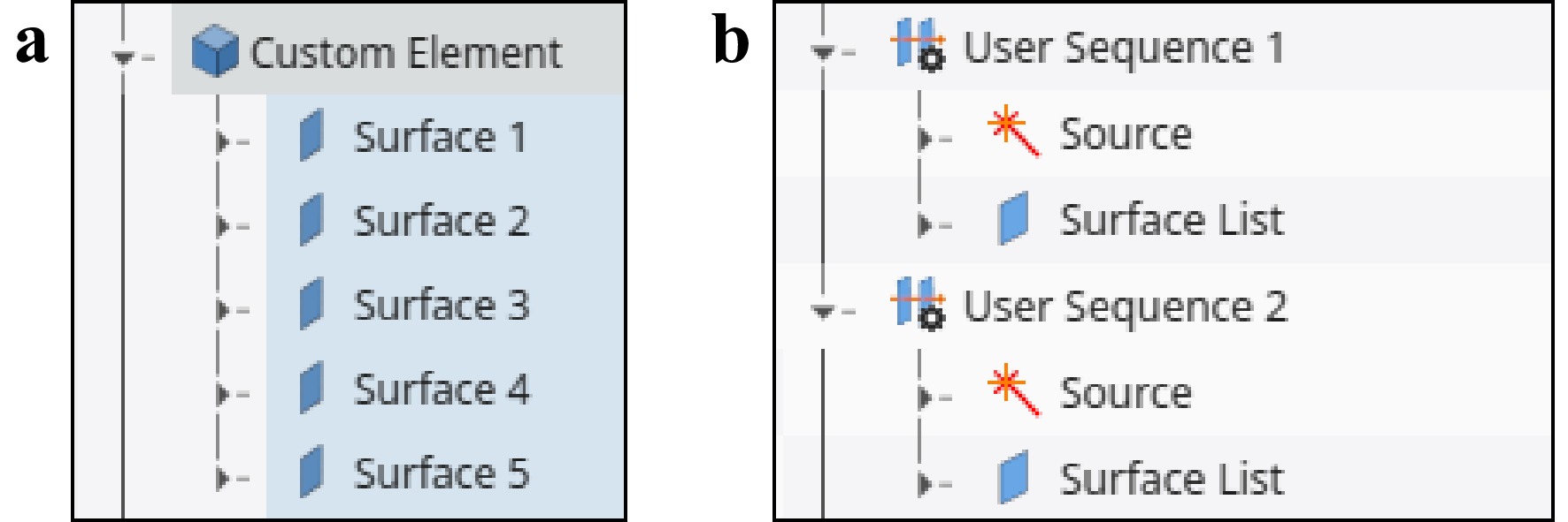
Fig. 9 Definition of the beam splitter cube: a Definition of the five optical surfaces of the cube inside a common element coordinate system b Definition of two sequences for the test and reference path. Each sequence holds a surface list to define the path for the ray trace (The complete surface list is collapsed and not visible in the figure).
-
Especially for high-end optical systems, the ability to perform a realistic tolerance analysis is crucial to reach the required system performance without the need for extremely tight tolerances. Unnecessarily tight tolerances often lead to high costs for the manufacturing of the optical elements, the mechanical mounts as well as the alignment. However, setting up a realistic tolerance analysis can often be challenging with state-of-the-art — list-based — optical design software. Our method provides several benefits that can be used to streamline the workflow:
- Complex mechanical dependencies can easily be implemented by grouping the optical elements into assemblies, just as they are grouped in the real-world setup.
- The surface stack ability allows to simulate a wide range of surface irregularities in the form of a sag deviation or a spatially dependent phase function. The flexible modular approach makes it possible to simulate a wide range of surface tolerances, from radius deviations or astigmatism to high-order Zernike polynomials, local surface deviation in form of Gaussian or super-Gaussian functions, periodic functions to simulate mid-spatial frequencies with different symmetries up to fully interpolated grids.
- The local element coordinate system allows the assignment of material inhomogeneities inside a local element coordinate system that is independent of any surface tolerances.
- In combination, all these features allow the straightforward implementation of a Structural Thermal Optical Performance (STOP) analysis with the following steps:
1. Export lenses as generic CAD format
2. Import lenses as well as the mechanical mounts to FEM software
3. Perform FEM analysis
4. Import the results back to our software package via the following methods:
1) Surface deformation can be added to the surface form stack
2) Element shifts and tilts are added to the element coordinate system
3) Assembly shifts and tilts are added to assembly coordinate systems
4) Index variations, e.g. due to thermal lensing, are assigned to the lens materials by adding interpolated GRIN profiles
The whole process can be automated via the scripting interface.
-
We have presented a new approach on how to set up the basic architecture of the data model for the use in optical design software or similar ray tracing software. Compared to the state-of-the-art — list-based approach — our architecture provides several advantages. The multi-sequential ray tracing is especially valuable for multi-pass systems or systems with more than one sequence, but is also useful for simple lenses in the field of ghost analysis. The hierarchical abstraction layer for handling coordinate systems offers significant advantages in designing of off-axis and free-form systems. Additionally it aids in tolerance analysis of classical on-axis systems as well as with the assignment of GRIN profiles. Furthermore, the flexible surface stack ability makes it easier to define arbitrary surface shapes and streamlines the tolerancing of spherical, aspherical and even freeform surfaces. In summary it has been demonstrated, that the high complexity that is often encountered in designing modern high-end optical systems is typically not caused by an intrinsic property of these systems, but rather emerges from s suboptimal choice of the underlying data structure used to model these systems.
-
This work was supported in parts by the EXIST-Gründungsstipendium (Grant No. 03EGSBW415) of the BMBF (german ministry for education and research).
A tree-like data structure for sequential and multi-sequential ray tracing
- Light: Advanced Manufacturing , Article number: (2025)
- Received: 25 October 2024
- Revised: 12 May 2025
- Accepted: 14 May 2025 Published online: 09 September 2025
doi: https://doi.org/10.37188/lam.2025.043
Abstract: In the area of computer-aided optical design most software packages rely on a surface list based data structure. For classical on-axis lenses — such as camera lenses — the list-based data structure is a suitable way for managing lens data. However, for modern high-end optical systems such as off-axis free-form designs, multi-path systems or for accurate tolerance analysis of complex opto-mechanical systems, the list-based approach often reaches its limits. In this paper we present a new tree-like data structure that is able to solve many of the problems that emerge from surface list based data structures.
Research Summary
An improved architecture for lens design and simulation software
An architecture to organize lens design and ray tracing data within an optical simulation or optical design software is presented. Compared to classical list based data structure the tree like data structure comes with multiple benefits. The separation between the sequential path information from the lens prescription data allows to define an arbitrary amount of sequential ray traces within a single model instead of just one. The modular surface approach enables an unprecedented freedom for the definition of lens geometries and optical properties. Furthermore, the method introduces a wide range of options to place lenses, assemblies or surfaces within local or global coordinate systems as well as the possibility to define index inhomogeneities or birefringence within well defined lens coordinate systems.
Rights and permissions
Open Access This article is licensed under a Creative Commons Attribution 4.0 International License, which permits use, sharing, adaptation, distribution and reproduction in any medium or format, as long as you give appropriate credit to the original author(s) and the source, provide a link to the Creative Commons license, and indicate if changes were made. The images or other third party material in this article are included in the article′s Creative Commons license, unless indicated otherwise in a credit line to the material. If material is not included in the article′s Creative Commons license and your intended use is not permitted by statutory regulation or exceeds the permitted use, you will need to obtain permission directly from the copyright holder. To view a copy of this license, visit http://creativecommons.org/licenses/by/4.0/.

 DownLoad: