


-
Ultrafast lasers, characterised by high temporal resolution and peak power, have become essential tools across a broad range of fields, including scientific research, biomedicine, materials processing, molecular sensing, mid-infrared (MIR) spectroscopy, and non-linear optics explorations1–8. Numerous molecular characteristic absorption peaks are observed within the 5–10 μm band compared with the near infrared band9,10. First, the distinctive fingerprint characteristics of 5–10 μm ultrafast lasers enable diverse biomedical applications, including cellular-scale precision in deep tissue ablation11,12. Second, the ultrashort pulse durations and high peak powers associated with these lasers make them crucial for material characterisation at the atomic and molecular scales and enable advanced scientific studies such as strong-field physics, providing comprehensive insights into light-matter interactions13–17. Additionally, these lasers are utilised in gas sensing to detect gases such as CH4, NH3, and NO2, leveraging their characteristic absorption peaks in the 5–10 μm band18. However, the absence of laser-guiding media capable of flexible transmission without altering the laser characteristics remains a limiting factor to the commercialisation of these lasers.
Optical fibres are the preferred solution for transmitting lasers in practical applications owing to their compact size and flexible laser delivery19. Several infrared glass fibres based on conventional solid-core designs are capable of operating within the 5–10 μm spectral range20,21. However, material non-linearity results in pulse broadening, making it challenging to transmit ultrafast MIR lasers22,23. Hollow-core fibres (HCFs), which use air as the laser-conducting medium, represent a significant advancement in overcoming material limitations in optical fibres. Although hollow-core photonic crystal fibres have achieved cut-off-free single-mode transmission, their transmission bandwidths remain relatively limited24. Hollow-core tube fibres internally coated with silver iodide have shown the potential for a broad transmission bandwidth25,26. Nevertheless, their large core size results in degraded mode quality of laser transmission and increased bending loss.
Anti-resonant hollow-core fibres (AR-HCFs) are ideal media for flexible transmission of ultrafast lasers. Via anti-resonance reflection, AR-HCFs can confine more than 99.9% of the laser energy within the air core, offering advantages such as low non-linearity, minimal dispersion, reduced delay, and high damage threshold27–30. Studies have demonstrated that the transmission bandwidth can be extended beyond 4 μm across multiple bands by strategically designing the cladding capillary thickness31. The design of the cladding structure enables individual leakage of higher-order modes, thereby facilitating single-mode transmission characterised by a large mode-field area32,33. Consequently, laser conduction via AR-HCF optimises the laser mode, resulting in a high-quality beam output34,35. In addition, the hollow-core design facilitates gas introduction, supporting investigations on laser non-linearities, gas sensing, and gas lasers36–39. However, the operation of AR-HCF in the MIR region, particularly for wavelength exceeding 5 μm, suffers from increased fibre loss resulting from the high material loss of silica glass40–44, which necessitate the development of novel AR-HCFs.
Fabricating AR-HCF based on tellurite glass, which exhibits lower material loss and higher transparency in the infrared spectrum than silica glass, is a candidate approach to further broaden the transmission band. Compared with other infrared glasses, tellurite glass provides a higher laser damage threshold, enhanced water erosion resistance, and greater chemical stability45. Currently, few reports on AR-HCF based on tellurite glass are available, and their performance remains suboptimal. The main challenge is the drastic viscosity changes in the tellurite glass near its glass transition temperature, which complicates the drawing process of tellurite AR-HCF. This imposes a greater demand on the manufacturing precision and processing of tellurite AR-HCF. In addition, the performance characteristics of the tellurite AR-HCF are not well understood.
In this study, we propose an AR-HCF based on tellurite glass for transmitting femtosecond pulses in the 5–10 μm MIR spectral range. Through theoretical simulations and experimental measurements, we demonstrate that the tellurite AR-HCFs are capable of transmitting lasers at wavelengths up to 10 μm. This fibre can withstand MIR femtosecond lasers with a peak power of 16 MW, while preserving their temporal and spectral characteristics. In addition, it enhances the beam quality of the laser via a higher-order mode leakage mechanism, reducing M2 from 1.5 to 1.25. We successfully achieve femtosecond laser ablation of biological tissues at 5.75 μm through the fibre, with an ablation threshold 50% lower than that of free-space laser delivery methods. This tellurite AR-HCF opens new possibilities for high-intensity ultrafast laser applications within the 5–10 μm range, such as minimally invasive biological tissue ablation and MIR gas laser generation.
-
The minimal overlap between the mode and surrounding material primarily decouples the AR-HCF from material constraints, enabling it to transmit lasers at longer wavelengths than the solid-core optical fibres of the same material. However, this also introduces uncertainty in the longest wavelength transmitted by the AR-HCF. In this study, simulations were conducted to investigate the longest theoretical laser wavelength that can be transmitted by tellurite AR-HCFs. Fig. 1a presents a schematic of the AR-HCF structure used in the simulation, in conjunction with the values of each parameter. To determine the longest laser wavelength transmitted by the tellurite AR-HCF, the core diameter (D) and capillary wall thickness (t) were treated as wavelength-dependent variables to achieve optimal performance at each wavelength. The capillary inner diameter (d) was set to 0.68 times the core diameter to optimise the leakage of higher-order modes32. The order (m) is a positive integer, and the outer cladding wall thickness (T) was set at 40 µm. Under these constraints, the AR-HCF structure had optimal parameters at each wavelength. Therefore, all the simulations in this section were conducted using the optimal structure for each wavelength to achieve the best performance of the tellurite AR-HCF across different wavelengths.
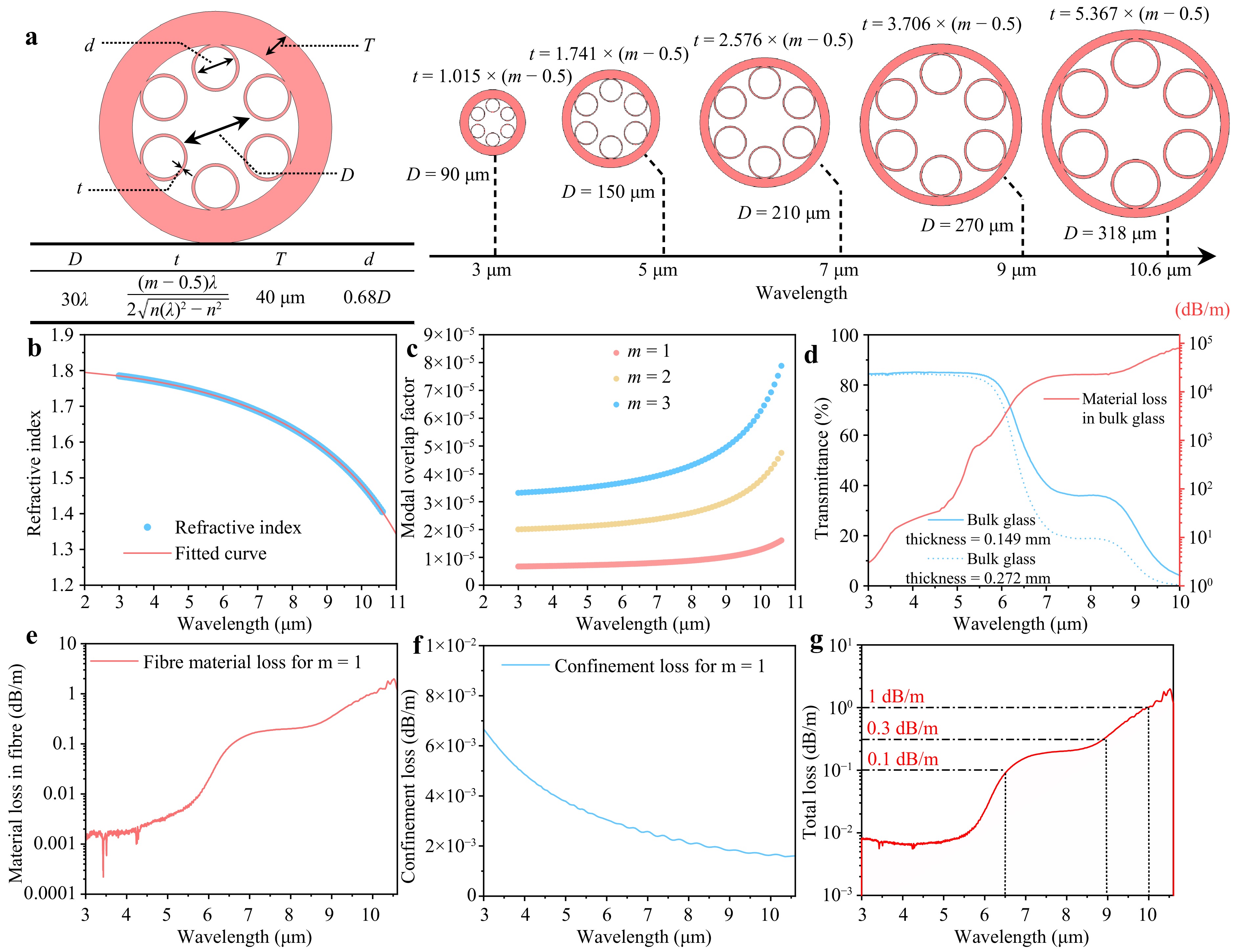
Fig. 1 Simulation results based on wavelength-dependent optimisation of the AR-HCF structure. a Structure schematic of tellurite AR-HCF and setting of each structural parameter; Exemplary AR-HCF structures at wavelengths of 3, 5, 7, 9, and 10.6 μm. b Refractive index (blue-dotted) and fitted curve (red-solid) of tellurite bulk glass. c Mode overlap factor for corresponding structures at different wavelengths when m = 1 (red-dotted), 2 (yellow-dotted), 3 (blue-dotted). d Infrared transmission curves for different thicknesses (blue-dashed for 0.272 mm and blue-solid for 0.149 mm) of tellurite glass and the calculated material loss curve (red-solid). e Calculated fibre material loss (red-solid) for m = 1. f CL from simulation (blue-solid) for m = 1. g Calculated total loss of tellurite AR-HCF.
Fig. 1b presents the refractive index and fitted curve of tellurite glass for AR-HCF manufacturing across the 2–11 µm range. The simulated data are calculated based on the structure and refractive index, which is modelled using COMSOL Multiphysics via the finite element method over the 3–10.6 µm band. Fig. 1c illustrates the simulated modal overlap factors for the tellurite AR-HCF across different m (m = 1, 2, 3). When m is fixed, based on Eq. 2, 4, because D is set to 30 times the wavelength (λ), the mode overlap factor (η) increases as the refractive index (n) decreases. Additionally, for varying m values, the mode overlap factor is proportional to (m – 0.5) at a constant wavelength. According to Eq. 3, the fibre material loss (FML) equals the product of mode overlap factor and the bulk material loss. Therefore, a series of structures at different wavelengths with the smallest mode overlap factor (m = 1) was selected. Fig. 1d shows the infrared transmission spectra of the two tellurite glass samples with thicknesses of 0.149 and 0.272 mm. The calculated material loss of the tellurite bulk glass at multiple wavelengths is depicted by a red solid curve. The calculated material loss remains below 400 dB/m up to 5 μm, contributing minimally to the total fibre loss in this range (<0.0028 dB/m). Beyond 5 μm, the material loss increases gradually. Despite the high material absorption loss in the 6–10 μm band, the extremely low overlap between mode and material in the AR-HCF (less than 0.01%) enables the transmission of 5–10 μm lasers in tellurite AR-HCF. Fig. 1e displays the FML of the tellurite AR-HCF which was calculated by multiplying the mode overlap factor of the optimal structure at each wavelength at m = 1 by the bulk glass material loss. The simulated confinement loss (CL) of the optimal structure at each wavelength for m = 1 is shown in Fig. 1f. CL decreases as the wavelength increases, which is associated with a decrease in the refractive index. The calculations indicate that the FML significantly exceeds the CL in the band above 6 μm, making it the primary contributor to the total loss of tellurite AR-HCF. The theoretical minimum total loss of the tellurite AR-HCF, which can be achieved at different wavelengths, calculated using Eq. 3, is shown in Fig. 1g. Despite substantial material losses, the low modal overlap factor enables the tellurite AR-HCF to transmit lasers within the 5–10 µm band. The calculated total loss that tellurite AR-HCF can achieve at different wavelengths remains below 0.1 dB/m up to 6.5 μm, below 0.3 dB/m up to 9 μm, and approaches approximately 1 dB/m at 10 μm. This represents a significantly broader transmission range than that of silica AR-HCF (for comparative data between silica and tellurite AR-HCF, see Supplementary Fig. S2). Theoretical calculations demonstrate the capability of tellurite AR-HCF to transmit lasers within the 5–10 μm range. Given the properties of tellurite glass and AR-HCF, tellurite AR-HCF is unlikely to exhibit material non-linear effects in the 5–10 μm band, making it an ideal choice for ultrafast laser transmission in this range.
-
The tellurite AR-HCF preform was prepared via the “stack-and-draw” method. Fig. 2a, b show the tellurite glass tubes of different sizes used in the fibre preform preparation processes. A thin-walled tube with an outer diameter of 18 mm and inner diameter of 14.4 mm was drawn into thin tubes with an outer diameter of 2.2 mm. The outer walls of all the tubes were polished to eliminate surface defects. Six thin tubes were equally immobilised within a jacket tube with an outer diameter of 14 mm and inner diameter of 10 mm, followed by heating near the Tg (glass transition temperature) of tellurite glass for 30 min to bond the thin tubes and jacket tubes. The fibre preform is illustrated in Fig. 2c. Fig. 2d presents a schematic of the AR-HCF fabrication process. During the fibre-drawing process, the air core and capillary tubes of the fibre preform were subjected to differential pressures using a custom dual-pressure control system. As shown in Fig. 2e, the pressure in the capillary (Pcapillary) must be greater than the core pressure (Pcore) to preserve the capillary roundness. Notably, the Pcore in the AR-HCF with a non-touching capillary structure must be greater than or equal to the pressure outside the jacket tube to prevent deformation of the jacket tube. A cross-sectional image of the tellurite AR-HCF obtained using a reflection microscope is shown in Fig. 2f. The diameter of tellurite AR-HCF is approximately 420 µm and the capillary wall thickness is approximately 2.3 µm. The difference in the capillary diameter is attributed to the deviation between the centre of the fibre preform and the drawing furnace temperature zone.
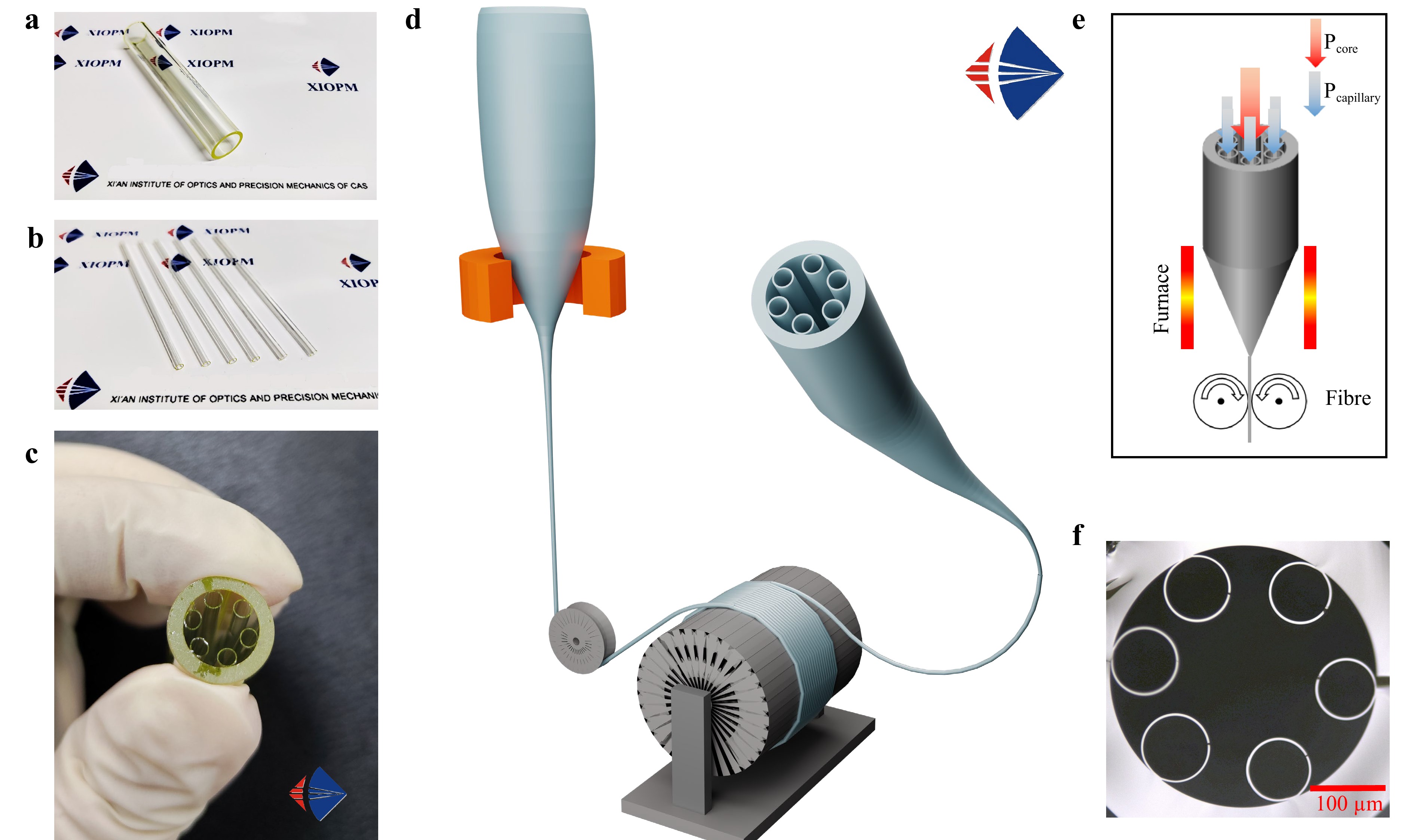
Fig. 2 Tellurite AR-HCF fabrication. a Tellurite glass tube with outer diameter of 18 mm and inner diameter of 14.4 mm. b Tellurite glass tubes drawn from a) with outer diameter of 2.2 mm. c Tellurite AR-HCF preform. d Schematic of the tellurite AR-HCF drawing process. e Schematic of air pressure control during fibre fabricating. f Cross-section image of the tellurite AR-HCF. (a and b were reproduced from Ref. 53 under a Creative Commons Attribution (CC BY) license.)
-
Fig. 3a, c show two tellurite AR-HCFs with capillary wall thicknesses of 3.3 µm (Fibre A) and 4.3 µm (Fibre B), each featuring a six-tube non-touching structure. To match the wavelength of the transmitted laser (5.75–6 μm), the fabricated tellurite AR-HCF were fabricated with a core diameter of approximately 180 µm and an outer diameter of nearly 420 µm. The inner diameters of the capillaries are listed in the table shown in the figure. These fibres exhibited robust structural stability across lengths of > 30 m. Fig. 3b shows the loss characteristics of fibre A measured via the cutback method employing Fourier transform infrared spectroscopy (FTIR) and a homemade optical parametric amplifier (OPA) source. The loss curves reveal alternating high and low-loss zones, with 1st, 2nd, and 3rd order anti-resonance low-loss regions at 9.5, 6, and 3.75 µm, corresponding to the capillary wall thickness and glass refractive index. Notably, the loss remains below 1 dB/m in the 3.5–3.9 and 5–5.5 µm bands, with loss in the 6 µm region ranging from 1 to 2 dB/m. The 9–10 µm band shows higher losses (10–11 dB/m), aligning with simulations that predict transmission up to 10 µm. Fig. 3d presents the results for Fibre B, demonstrating that thicker capillary walls shift the anti-resonance regions to longer wavelengths. Its 2nd and 3rd order low-loss regions occur at 7.8 and 5.2 µm, each with a 2 dB/m loss. The FTIR results are consistent with those from the OPA and quantum cascade laser (QCL) measurements. The increased loss in the 3–5 µm range is attributed to variations in wall thickness, which cause overlaps between higher-order anti-resonance and resonance regions. The combined data confirm that tellurite AR-HCFs are capable of transmitting the 5–10 µm lasers, surpassing the performance of tellurite solid-core fibres (<4.3 µm) and silica AR-HCFs (~6 µm). In practice, the bending capacity of a fibre is equally important. The bending radius was reduced to less than 8 cm after coating, as shown in Fig. 3e. The simulation results of the CL and transmission loss (TL) of the tellurite AR-HCF at different bending radius for a wavelength of 5.75 µm and capillary wall thickness of 3.3 µm (Fibre A) are given in Fig. 3f. For bending radii exceeding 25 cm, the CL and TL values converged for different bending directions, with TL marginally exceeding CL owing to the relatively small CL, which emphasises the impact of material loss. By contrast, at bending radii below 25 cm, CL increased, and the bending direction more significantly influenced the loss of the fibre. The simulation results indicated that the bending loss remained below 1 dB/m when the bending radius exceeded 15 cm. The low bending loss enables the tellurite AR-HCF to maintain an adequate laser conduction capability during practical applications involving bends.
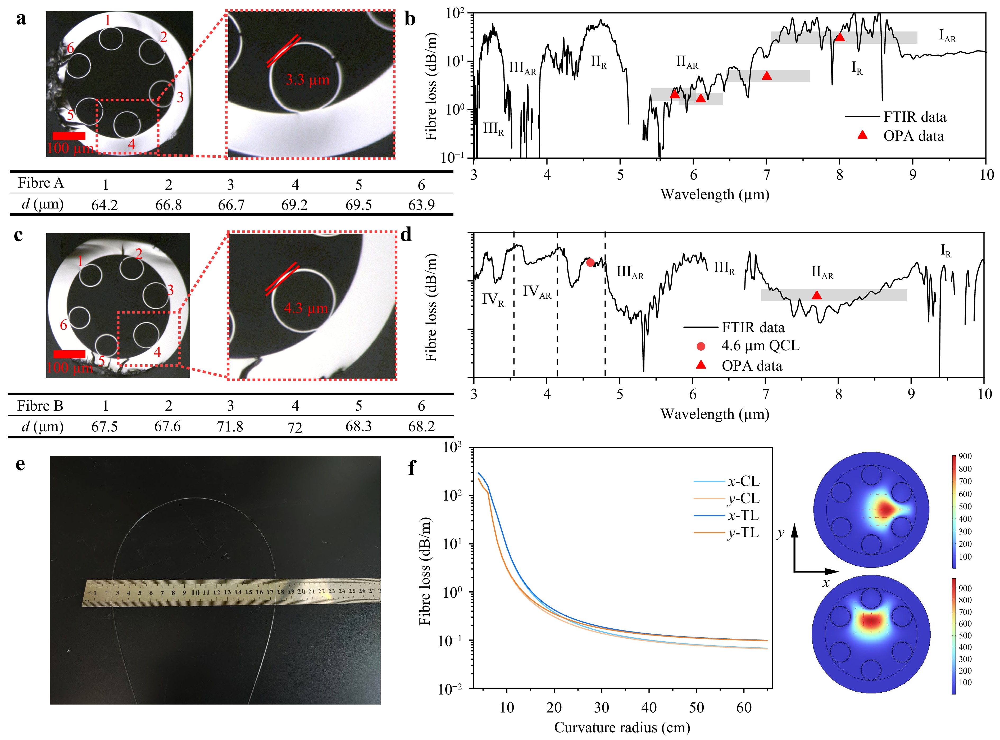
Fig. 3 Tellurite AR-HCF characterisation. a Cross-section of tellurite AR-HCF with wall thickness of 3.3 μm. b Loss curve of fibre in a measured via FTIR (black-solid) and tuneable OPA (red triangle and shaded portion). c Cross-section of tellurite AR-HCF with wall thickness of 4.3 μm. d Loss curve of fibre in c measured via FTIR (black-solid), tuneable OPA tests (red triangle and shaded portion) and 4.6 μm QCL (red dot). e Tellurite AR-HCF with coating bent to a radius of 8 cm. f Simulated CL and TL of tellurite AR-HCF at different bending radius for a wavelength of 5.75 µm and capillary wall thickness of 3.3 µm, in conjunction with mode-field images for 15 cm bending along the x- and y-directions.
-
Fig. 4a depicts the optical setup of the OPA system, which was designed to produce MIR femtosecond lasers and transmit them via a tellurite AR-HCF. The OPA achieved a maximum average output power of approximately 200 mW at 5.75 μm, exhibiting a 6 mm beam diameter and M2 factor of 1.5. A 50 mm focal-length CaF2 plano-convex lens was utilised to focus the collimated output laser before it was coupled to the tellurite AR-HCF. Infrared pulses from the OPA and fibre output were analysed using a custom interferometric autocorrelator (IAC). Simultaneously, the laser power and mode profiles were recorded using a power metre and infrared charge-coupled device camera, respectively. Fig. 4b displays experimental and reconstructed IAC traces of the 5.75 μm MIR pulses emitted by the OPA, achieving a temporal resolution of approximately 229 fs via pulse retrieval analysis. The inset shows a mode-field image of the laser output from the OPA. Fig. 4c illustrates the normalised output spectra of the wavelength-tuneable OPA, showing continuous spectral coverage from 5 to 12 μm.
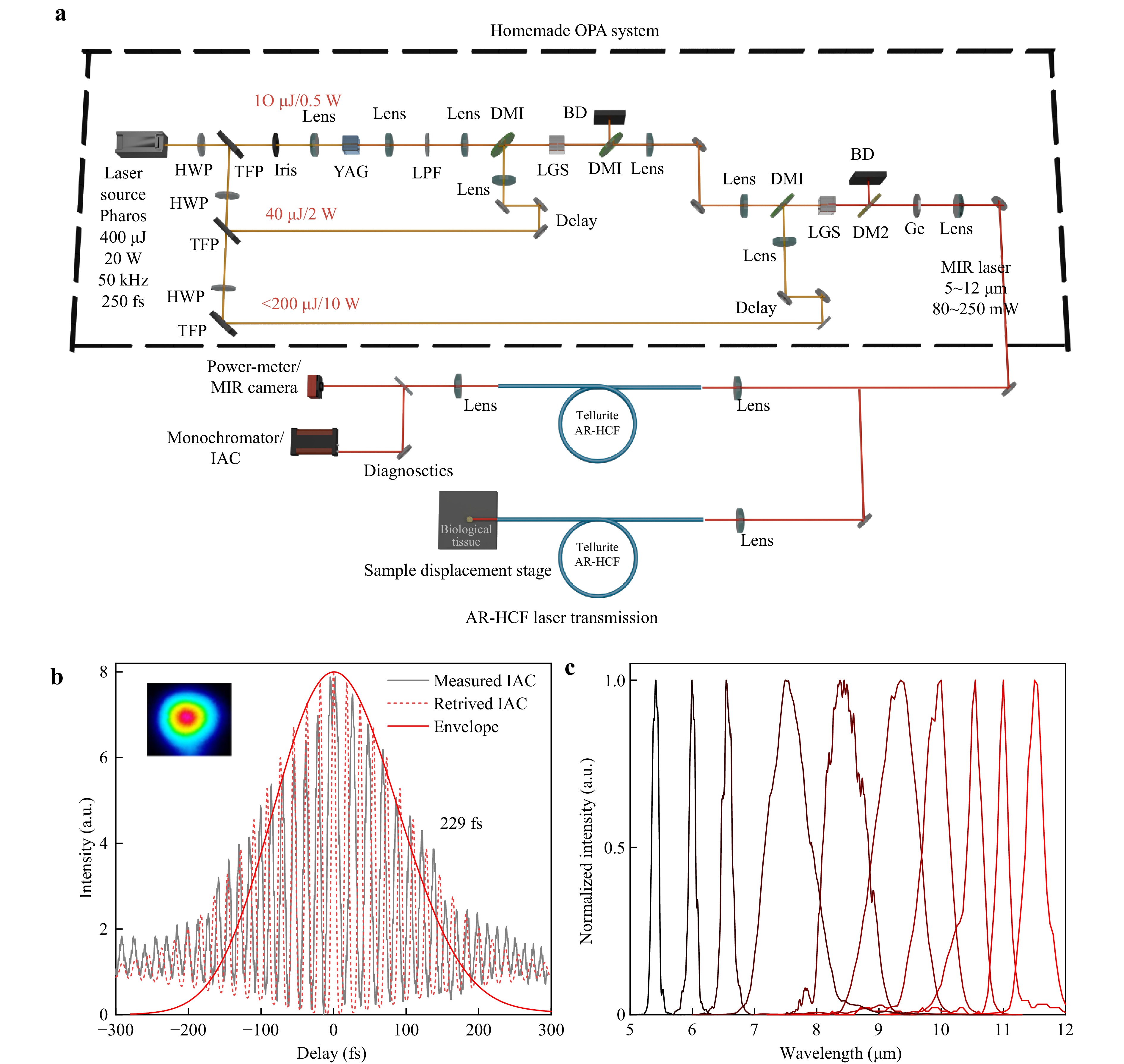
Fig. 4 MIR ultrafast laser experimental setup. a Schematic of the experimental optical path for MIR femtosecond laser transmission, including a homemade OPA system and tellurite AR-HCF transmission system. HWP, half-wave plate; TFP, thin film polariser; YAG, yttrium aluminium garnet crystal; LPF, long-pass filter; DM1, dichroic mirror (HT@1135–1600 nm, HR@1030 nm); LGS, 8-mm-thick LiGaS2 crystal; DM2, dichroic mirror (HT@5–11 μm, HR@1030 nm); BD, beam dump; Ge, germanium window (3–12 μm, AR coated). b Measured (black-solid) and retrieved (red-dotted) interference autocorrelation traces of the delivered MIR pulses from output of laser system at 5.75 μm and corresponding retrieved temporal profile (red-solid); Inset: OPA output laser mode field. c Normalised curves of tuneable laser spectra at 5–12 µm from OPA system.
-
Fig. 5a-d show normalised spectra comparing the OPA source and fibre output across 5–9 µm wavelengths for 80-cm-long Fibre A, demonstrating effective laser transmission up to approximately 7 µm. The transmission capability ceased abruptly beyond 7.5 µm. Fig. 5e presents the normalised input-output spectra of 30-cm-long Fibre A within the 6.5–10 µm range, revealing extended transmission beyond 10 µm. However, detecting signals in this region requires shorter fibre lengths owing to high fibre attenuation and limited source power. Measured losses were 2 dB/m at 5.75 µm, 1.65 dB/m at 6.1 µm, 4.8 dB/m at 7 µm, and over 30 dB/m at 8 µm. Although these broadband measurements do not represent single-wavelength fibre losses, they align with the simulated CL and total loss profiles shown in Fig. 5f, and effectively correlate with the FTIR-derived loss trends. Owing to the loss at 8.5–10 µm (14 dB/m) being higher than that at 7–7.5 µm (4.8 dB/m), no signal was detected within the 80-cm-long fibre (Fig. 5d), whereas the 30-cm-long fibre (Fig. 5e) exhibited measurable output, consistent with Fig. 5f; the fibre loss started decreasing at 8.5 µm. Fig. 5g shows the laser power at the incident light-focusing lens and the output from a 40-cm-long fibre when the OPA wavelength was set to 5.75 μm. The coupling efficiency at the incident end was approximately 60%, based on the loss of the fibre (2 dB/m) at this wavelength. The coupling performance can be enhanced by optimising the focusing spot size. Fig. 5h compares experimental and reconstructed interferometric autocorrelation traces of fibre-delivered 5.75 µm pulses, demonstrating a temporal resolution of approximately 240 fs. The 11-fs temporal broadening, compared with the OPA output of 229 fs shown in Fig. 4b, primarily originated from the ZnSe lens, confirming negligible fibre-induced temporal distortion.
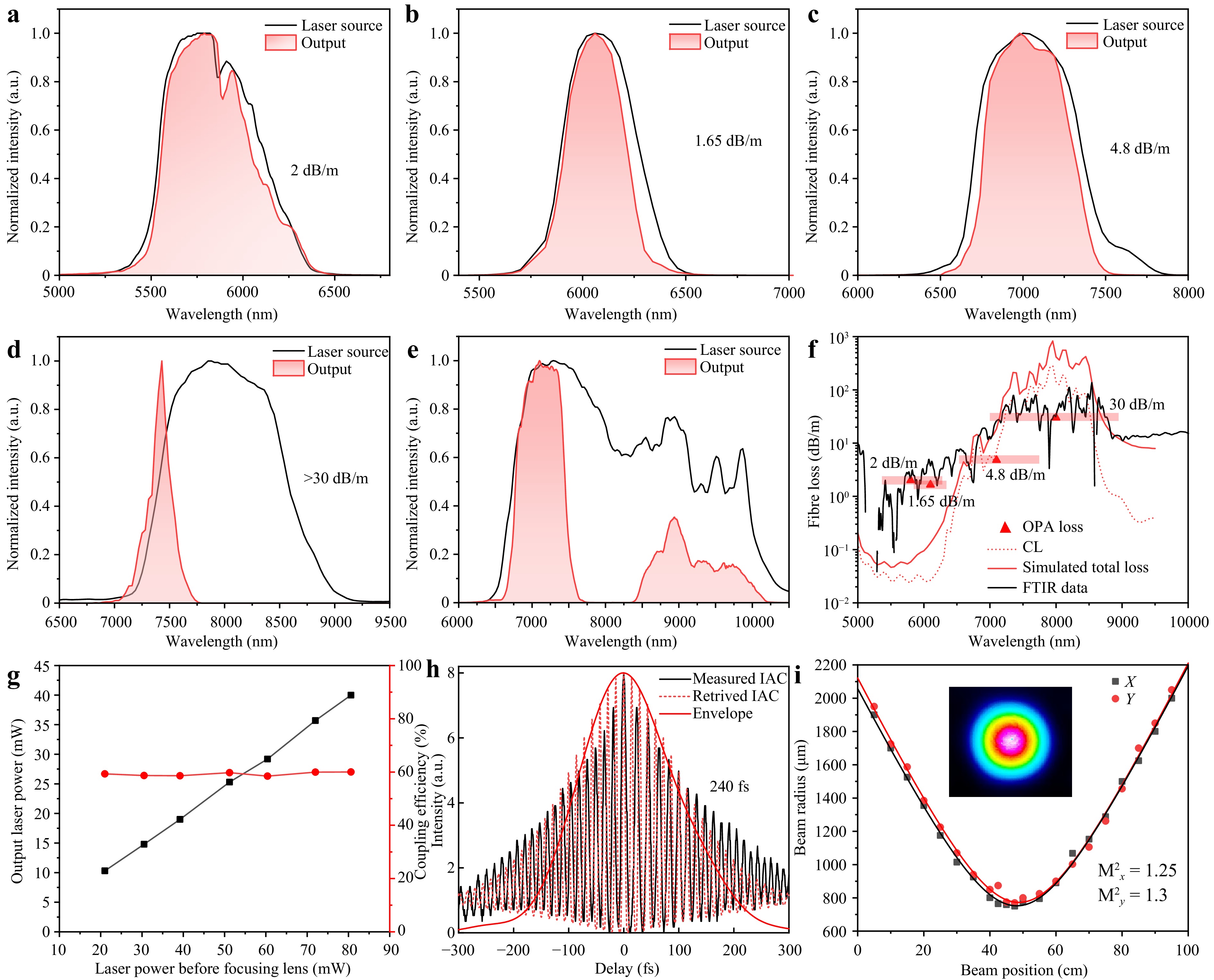
Fig. 5 Fibre output ultrafast laser characterisation. Normalised spectral intensity profiles of the OPA system laser source (black-solid) and Fibre A output lasers (red area) within the spectral range of a 5.3–6.4 μm; b 5.7–6.5 μm; c 6.5–7.7 μm; d 7.05–9 μm; e 6.5–10.5 μm. f Simulated CL (red-dashed), simulated total fibre loss (red-solid), FTIR loss (black-solid) and wide spectrum loss of OPA (red triangle and shadow). g OPA laser power and fibre output power (black dot line) and calculated coupling efficiency (red dot line) at 5.75 μm. h Measured (black-solid) and retrieved (red-dashed) interference autocorrelation traces of the delivered MIR pulses from output of tellurite AR-HCF at 5.75 μm and corresponding retrieved temporal profile (red-solid). i Output beam quality of a 20-cm-long tellurite AR-HCF at 5.75 μm.
Spectral comparisons confirmed that the tellurite AR-HCF introduces minimal distortion to the input femtosecond pulses, in contrast to solid-core fibres. The fibre output exhibited marginal spectral narrowing owing to the anti-resonance band characteristics instead of broadening. Fig. 5i shows the mode-field image and beam quality fitting results for the laser output from the tellurite AR-HCF at 5.75 μm. The laser mode-field output from the fibre showed superior performance compared with the OPA output in Fig. 4b, with M2 values of 1.25 and 1.3 in the x- and y-directions, respectively. Evidently, this fibre enhances the laser performance, resulting in an improvement in the beam quality after transmission. This enhancement is attributed to the higher-order mode leakage mechanism of the AR-HCF, which increases the fundamental mode purity of the transmitted laser. Increasing the fibre length is expected to further reduce M2 and enhance laser quality. These superior beam properties provide dual clinical benefits, including enhanced energy density, which lowers the required input power and reduces collateral damage.
-
In atherosclerotic lesions, cholesterol accumulates within the intima of blood vessels via the formation of ester bonds with fatty acids like oleic acid46. Therefore, cholesteryl esters are the primary components of atherosclerotic plaques47. Fig. 6a displays the absorption spectra for artery and ester within the 3–9 μm band. Ester exhibited characteristic absorption at 3.45, 5.75, and 8.6 μm, whereas artery showed minimal absorption at 5.75 μm. Consequently, 5.75 μm MIR ultrafast lasers target the C=O stretching vibration mode of ester bonds, sparing the vessel wall48,49. Preliminary experiments were conducted to evaluate the efficacy of the tellurite AR-HCF in delivering 5.75 μm femtosecond pulses aimed at atherosclerotic plaque ablation. As shown in Fig. 6b, a 40 mW, 50 kHz, 240 fs laser output from the AR-HCF, with a single-pulse energy of 800 nJ and peak power of approximately 3.13 MW, effectively achieves ester resonant ablation owing to its absorption by the ester bond. Fig. 6c shows ablation craters in fat specimens, measuring 150 μm in diameter and 150–200 μm in depth. Notably, the power required for cholesterol ester ablation using tellurite AR-HCF was 50% less than the previously reported ~80 mW for spatial ablation12, with a peak laser intensity below the ~40 GW/cm2 required for spatial ablation. This power reduction is attributed to the mode-shaping capability of the AR-HCF, which enhances the energy efficiency. Fig. 6d compares the samples before and after atherosclerosis ablation using the same laser, illustrating effective plaque removal without compromising the arterial wall integrity. These experiments highlight the potential of tellurite AR-HCFs for tissue ablation and cutting in living organisms. This process involves utilising its broadband transmission and ultrafast laser property retention capabilities to deliver high-quality 5–10 μm ultrafast lasers for efficient and precise target tissue ablation. Fig. 6e illustrates a conceptual future implementation of the tellurite AR-HCF in vascular interventions for atherosclerosis treatment, with its broader application in medical laser surgery anticipated soon after. Although preliminary, these findings indicate that tellurite AR-HCFs represent a promising platform for delivering 5–10 μm ultrafast lasers in minimally invasive vascular interventions.
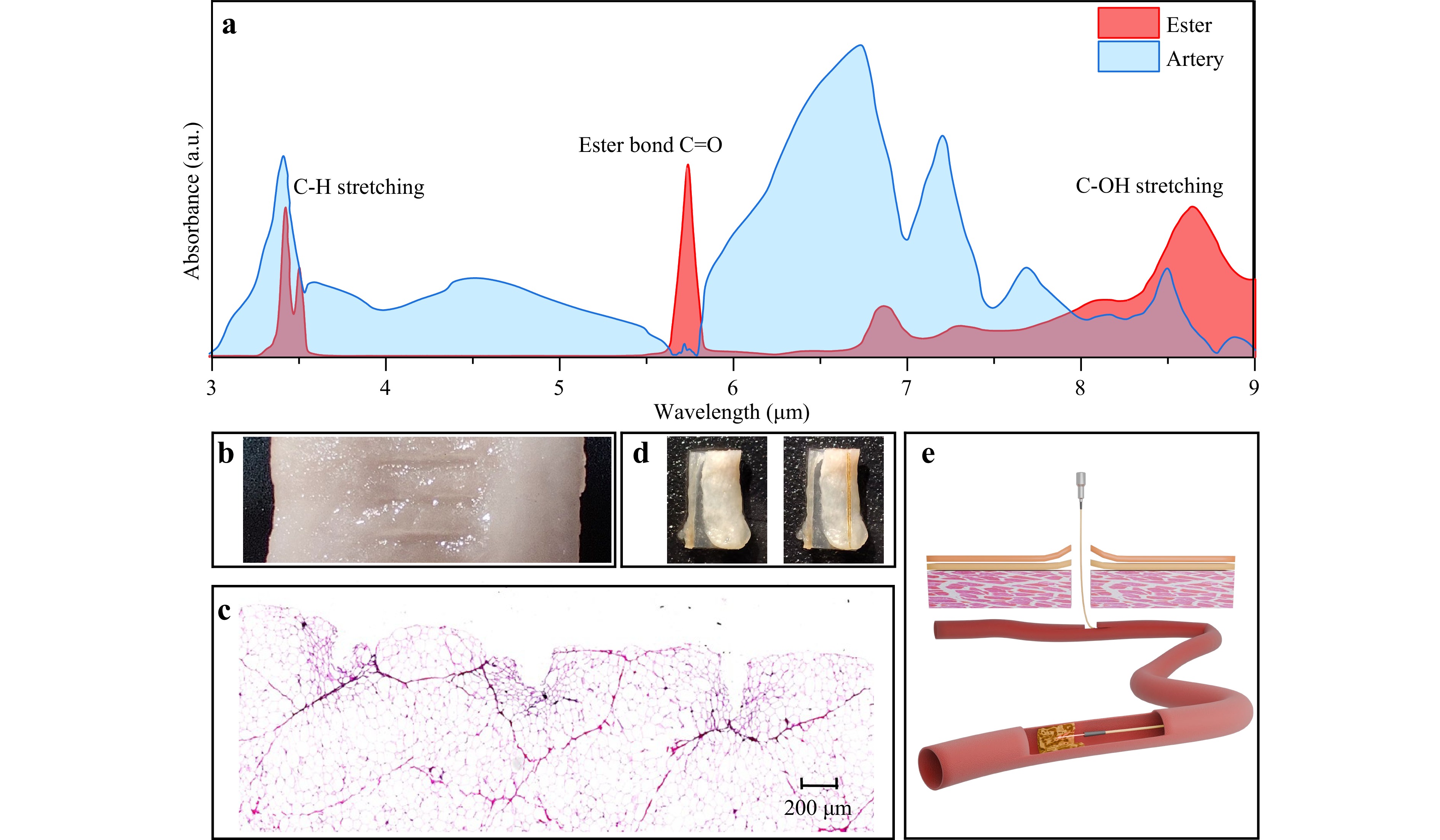
Fig. 6 Fibre output of a 5.75 μm ultrafast laser for biological tissue ablation. a Absorbance of ester and artery within the 3–9 μm band. b Sample diagram and c cross-sectional diagram of animal fat samples ablated by 5.75 μm femtosecond laser transmitted through a tellurite AR-HCF. d Atherosclerosis samples before and after ablation by 5.75 μm femtosecond laser transmitted through a tellurite AR-HCF. e Conceptual diagram of tellurite AR-HCF for atherosclerosis ablation interventions.
-
In this study, we designed and fabricated a tellurite glass-based AR-HCF and investigate its capability for transmitting femtosecond lasers. The experimental results indicated that the tellurite AR-HCF did not affect the temporal and spectral properties of the transmitted femtosecond lasers, achieving an input peak power of 16 MW. Leveraging the high infrared transmittance of the tellurite glass and optimised mode-field overlap of the AR-HCF, the tellurite AR-HCF successfully extended its laser transmission window to the 10 μm wavelength range. Preliminary laser ablation experiments on biological tissues were conducted using a 5.75 μm femtosecond laser transmitted through the tellurite AR-HCF. The efficient and high-quality delivery of the MIR ultrafast laser through the tellurite AR-HCF reduced the laser power threshold for ablation by up to 50% compared with that observed through the direct use of the OPA spatial laser. This feature makes them extremely promising for flexible transmission of MIR femtosecond lasers in the field of minimally invasive medical surgery.
The absorption characteristics of biological macromolecules within the 5–10 μm MIR spectral range provide MIR ultrafast lasers high sensitivity and molecular recognition capabilities. These features make them promising tools for transmitting specific-wavelength lasers in this band through a tellurite AR-HCF for selective cutting and ablation. Future investigations should focus on the application of a protective coating and end-sealing to the tellurite AR-HCF to facilitate in vivo tissue ablation experiments. The anticipated challenges include increased loss under bending, end-face treatment, encapsulation, and reduced service life under high-power laser transmission. Despite these challenges, the tellurite AR-HCF developed in this study emerges as a novel candidate for the application of ultrafast MIR lasers in medicine.
Additionally, the high laser-damage threshold renders tellurite AR-HCFs suitable for high-power gas laser research (e.g., CO, CO2, N2O) in the 5–10 μm band. To address the increased loss in the 10 μm band, optimising the tellurite composition ratio and enhancing infrared transmission are suitable approaches as they can further extend the transmission band of tellurite AR-HCFs. In conclusion, the tellurite AR-HCF demonstrates significant potential for advancing minimally invasive, non-destructive, and flexible ablation procedures in medical applications. This technology is expected to provide extensive applications in medical therapy and other MIR laser fields.
-
The transmission performance of the tellurite AR-HCF was modelled using the finite element method. The refractive-index dispersion curve of the tellurite glass can be fitted using the Sellmeier formula:
$$ {n}^{2}=~1+\frac{a{\lambda }^{2}}{{\lambda }^{2}-{b}^{2}}+\frac{c{\lambda }^{2}}{{\lambda }^{2}-{d}^{2}}+\frac{e{\lambda }^{2}}{{\lambda }^{2}-{f}^{2}} $$ (1) where n is the refractive index; λ is the wavelength; and a, b, c, d, e, and f are the coefficients of the Sellmeier formula. The Sellmeier coefficients, used in the numerical modelling of the tellurite AR-HCF, are listed in Table 1.
a b c d e f TBLL 1.7005 1.81371 × 10⁻⁷ 0.54879 3.65985 × 10⁻⁷ 1.90928 16.75693 Table 1. Sellmeier coefficients of tellurite glass
To ascertain the optimal performance of the fibre at varying wavelengths, the cladding capillary wall thickness was calibrated to the mth-order anti-resonance wall thickness at the corresponding wavelength, aligning with the anti-resonance equation50:
$$ t=\frac{(m-0.5)\lambda }{2\sqrt{{n}^{2}-n_{0}^{2}}} $$ (2) where t denotes the cladding capillary wall thickness, and n0 is the refractive index of air (the default value is 1). The total loss αtotal of AR-HCF is defined as51
$$ {\alpha }_{total}={\alpha }_{CL}+\eta {\alpha }_{m} $$ (3) where αCL is the CL, αm is the material loss, and η is the modal overlap factor. Based on the formulae provided in the literature52,
$$ \eta \propto {\left(\frac{\lambda }{\mathrm{D}}\right)}^{2}\cdot \frac{\mathrm{t}}{\mathrm{D}} $$ (4) where D denotes the core diameter. Accordingly, D was established at 30 times the wavelength, whereas the capillary inner diameter d was set to 0.68 times the core diameter. The number of capillary tubes was set to 6, and the thickness of the outer tube wall T is set at 40 μm. The mode overlap factor η was calculated from the simulated ratio between the z-direction Poynting vector integrals of the material portion and the entire fibre cross-section.
-
The glass composition used for fibre fabrication was 70TeO2-15BaF2-5La2O3-10LaF3 (TBLL), and its thermal and optical properties are detailed in our prior research53. TBLL exhibits a glass transition temperature (Tg) of 420 ℃ and thermal stability range (∆T) of up to 141.7 ℃. Comprehensive data are provided in the Supplementary Material.
Two types of thin-walled tellurite tubes, with outer/inner diameters of 18/14.4 mm and 14/10.4 mm, were fabricated employing the tube-turning method, and subsequently, their surfaces were precision-polished. The thin tubes essential for aligning the prefabricated rods were drawn from tellurite tubes with an outer diameter of 18 mm to achieve the desired capillary wall thickness. Prefabricated preforms were produced using a thermal bonding method in which the preform was heated near its Tg to bond the capillaries to the outer tube.
The tellurite AR-HCF preforms were drawn into optical fibres using an infrared drawing tower. During this process, special moulds facilitate pressure-filling operations in various regions. The external regions of the core and preform remained at atmospheric pressure, whereas the capillary interior experienced pressure.
-
The cross-sectional and dimensional data for the prepared tellurite AR-HCFs were acquired using a reflectance optical microscope. Fibre loss tests employed various laser sources, such as a Fourier infrared spectrometer, a 4.6 µm QCL, and a custom-built OPA system with a tuneable wavelength of 5–12 µm. The TL in the fibres was measured via the cutback method, with the average value calculated from the two truncations. Fibre lengths between 0.5 to 2 m were used for testing, based on the varying losses observed at different wavelengths. The output-beam mode field and laser-beam quality were measured utilising a laser-beam profiler (DataRay, WinCamD-IR-BB).
-
The OPA laser wavelength was set at 5.75 µm, corresponding to the characteristic absorption wavelength of the C=O double bond in ester bonds. Animal fat and atherosclerotic plaques primarily contain ester bonds; therefore, they were selected as the experimental ablation targets. Instead of using a focusing lens at the fibre-laser output, the laser was attached directly to the sample. The animal fat samples were ablated using a laser emitted from the fibre at a linear travel speed of 1 mm/s.
-
We are grateful for the financial support from the National Natural Science Foundation of China (Grant Nos. 62090065, 62090063, and 62005312), the Natural Science Foundation of Shaanxi Province (2023-JC-JQ-31, J23-016- III), and the Key Research and Development Programme of Shaanxi Province (2023-YBGY-426).
Tellurite anti-resonant hollow-core fibre: fabrication, mid-infrared femtosecond laser transmission, and application in tissue ablation
- Light: Advanced Manufacturing , Article number: 32 (2026)
- Received: 10 September 2025
- Revised: 26 January 2026
- Accepted: 03 February 2026 Published online: 28 March 2026
doi: https://doi.org/10.37188/lam.2026.032
Abstract: The absence of flexible fibres capable of delivering high-intensity mid-infrared ultrafast lasers (particularly at wavelengths exceeding 5 μm) without inducing pulse distortion or material damage constitutes a major limitation for numerous applications, including laser-based minimally invasive surgery, precision materials processing, and gas sensing. Herein, a tellurite glass anti-resonant hollow-core fibre is proposed that exhibits low transmission loss across the 5–10 μm band (~2 dB/m at 5.5–6 μm or 7.5–8 μm), robust bending resilience (minimum radius of 8 cm), and improved beam quality (output M2 reduced from 1.5 to 1.25). Notably, it facilitates the distortion-free delivery of ultrafast mid-infrared pulses from an optical parametric amplification system, without causing spectral broadening or material damage, at an input peak power of 16 MW. In a proof-of-concept demonstration, the developed fibre enables wavelength-selective ablation of biological adipose tissue at 5.75 μm, representing, to the best of our knowledge, the first such demonstration using tellurite hollow-core fibre platform. A record-wide operational bandwidth, extending to 10 μm, is achieved by leveraging the extended infrared edge of tellurite glass. This study confirms that tellurite anti-resonant hollow-core fibres can serve as groundbreaking tools in ultrafast mid-infrared photonics, offering significant potential for addressing challenges in invasive laser surgery, gas-phase spectroscopy, and non-linear optical studies.
Rights and permissions
Open Access This article is licensed under a Creative Commons Attribution 4.0 International License, which permits use, sharing, adaptation, distribution and reproduction in any medium or format, as long as you give appropriate credit to the original author(s) and the source, provide a link to the Creative Commons license, and indicate if changes were made. The images or other third party material in this article are included in the article′s Creative Commons license, unless indicated otherwise in a credit line to the material. If material is not included in the article′s Creative Commons license and your intended use is not permitted by statutory regulation or exceeds the permitted use, you will need to obtain permission directly from the copyright holder. To view a copy of this license, visit http://creativecommons.org/licenses/by/4.0/.

 DownLoad: