



-
Dielectric coatings capable of withstanding high-power lasers are essential for contemporary laser facilities. For instance, thousands of dielectric coatings are required to support inertial confinement fusion (ICF) lasers1,2, such as the National Ignition Facility (NIF) in the USA3, the Laser Megajoule (LMJ) facility in France4, and the Shen Guang (SG) series facilities in China5. The achievable performance of dielectric coatings directly affects the output of an entire laser system. Among various factors, the laser-induced damage threshold (LIDT)6 of coatings is critical for determining the output power of a laser system. Decades of research have focused on enhancing the LIDT of coatings. Studies have shown that defects, such as subsurface defects7, nodular defects8, and substrate pits9, often lead to significantly lower LIDT for coating materials compared to those of bulk materials. Substantial progress has been made in minimizing defect densities and improving the laser resistance of coatings through design, deposition, and post-treatment strategies, including E-field optimization10,11, nanolaminate design12,13, and deformation planarization14,15. Although the complete elimination of defects remains challenging, the selection of appropriate coating materials provides an effective approach to enhance LIDT.
SiO2 is the preferred coating material for ultraviolet (UV) to near-infrared (NIR) lasers because of its wide bandgap and low absorption loss. Typically, SiO2 serves as a low-refractive-index (low-n) layer material and is alternately deposited with high-n layer materials to achieve a specific spectral performance16. The LIDT of multilayer coatings is typically limited by the high-n layer material, which has a relatively low optical bandgap, making it prone to damage under laser irradiation17. If both high-n and low-n layers can be fabricated from SiO2-based materials, such as dense SiO2 and porous SiO2 layers18,19, the LIDT of the coating is expected to be significantly enhanced.
Numerous strategies have been proposed for obtaining low-n SiO2 layers. Sol-gel processes enable the fabrication of nanoporous SiO2 layers with adjustable porosities, resulting in high LIDT. This method is often used to produce anti-reflection (AR) coatings with few layers20–22. However, cracking becomes more prevalent when preparing coatings with multiple layers, making the fabrication of high-reflection (HR) coatings challenging23. The glancing angle deposition method, which tunes n values by varying the glancing angle, has been employed not only for preparing AR coatings24–26, but also for fabricating HR coatings27, polarizers28, and zero-order waveplates29. However, the non-uniformity of the coating poses challenges for large-scale optics30. Chemical etching of nanolaminates or mixed coatings can yield porous SiO2 coatings31. This technique has been successfully employed to prepare both single-wavelength32 and broadband33 AR coatings with high LIDT values. Despite the progress in porous coatings, methods suitable for preparing multilayer and large-size porous SiO2 for laser applications are yet to be developed.
This study proposes an advanced method that combines plasma-ion-assisted electron-beam co-evaporation and chemical etching to fabricate a laser-resistant porous SiO2 multilayer coating. Fig. 1 shows a schematic illustration of the multilayer coating structure. Coating fabrication involves two key processes: co-evaporation deposition and chemical etching, both of which are suitable for large-size coatings. During deposition, a multilayer coating composed of alternating Al2O3–SiO2 mixture and SiO2 layers was prepared. The Al2O3–SiO2 layers were deposited using dual electron-beam co-evaporation. Subsequently, the Al2O3 within the Al2O3–SiO2 mixture layers was selectively dissolved during the chemical etching process, yielding porous SiO2 layers with low-n values. The SiO2 layers remained unchanged after chemical etching and served as high-n layers in the new multilayer structure. The proposed strategy enabled the fabrication of HR and AR coatings with good spectral performance and high LIDT values. Notably, the AR coating exhibited an LIDT of 46.9 J/cm2 at 355 nm, surpassing that of the substrate (41.1 J/cm2). Thus, the proposed approach holds significant promise for widespread adoption in advanced laser systems and offers a cost-effective solution for multilayer coatings with superior performance.
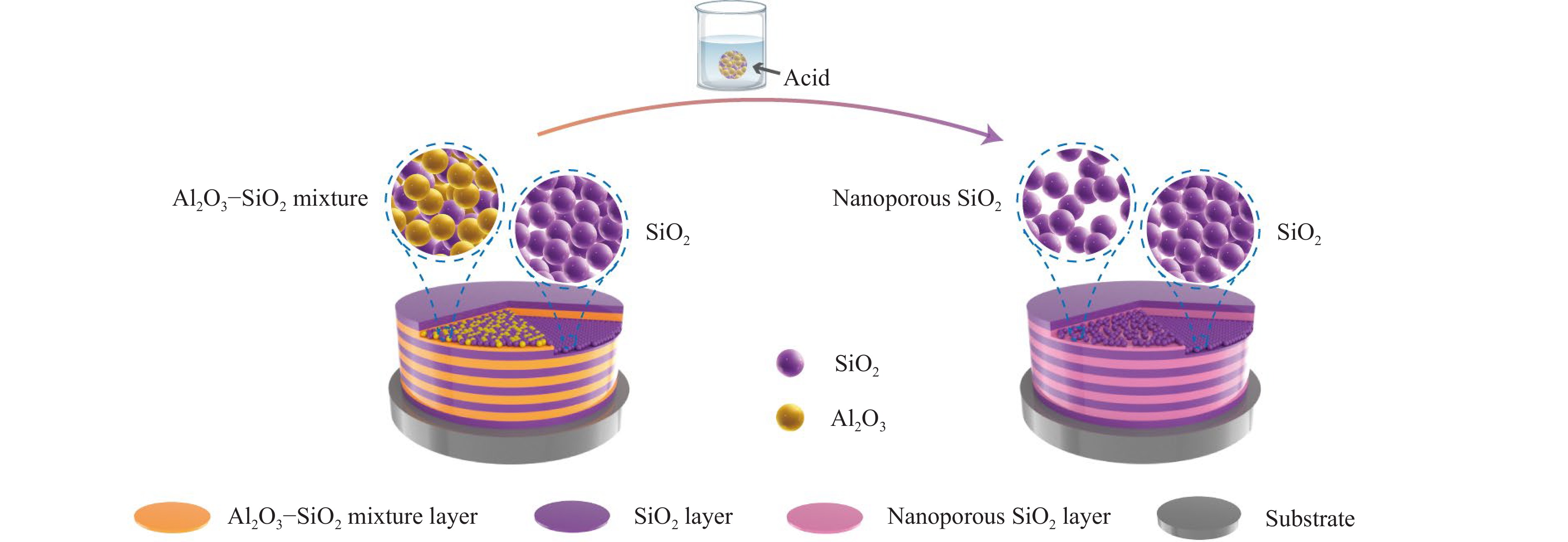
Fig. 1 Schematic of the coating structure illustrating a multilayer coating composed of nanoporous SiO2 layers.
-
Porous SiO2 layers were prepared by etching Al2O3–SiO2 mixture layers with an H3PO4 solution. The influence of the Al element ratio in the Al2O3–SiO2 mixture layers on the properties of the porous SiO2 layers was investigated. Fig. 2 shows the transmittance spectra of the as-deposited single-layer Al2O3–SiO2 mixture coatings, denoted as A-SLX (where X represents the measured Al ratio in the Al and Si elements), along with the transmittance spectra of the porous single-layer SiO2 coatings obtained after etching, denoted as P-SLX-H3PO4-T (where T refers to the duration of the chemical etching process). For A-SL51% (with an Al element ratio of approximately 51%), a significant change in the transmittance spectrum was observed when the etching duration was less than 3 h. Notably, the transmittance curves for 3 h and 4 h of etching overlapped closely, suggesting that the chemical reaction reached saturation within the initial 3 h. For A-SL57%, the chemical reaction nearly reached completion after 1 h of etching. Upon further increasing the Al element ratio to 65% to 77%, the spectral properties of the porous coating stabilized after 0.5 h of etching. During etching, Al2O3 reacts with H3PO4 to form soluble aluminum phosphate, while the SiO2 network remains relatively stable and does not participate in the reaction. This results in the selective dissolution of Al2O3 from the Al2O3–SiO2 mixture coatings, leading to pore formation. The removal rate of Al2O3 is co-limited by the chemical reaction rate and the solution diffusion rate, with the pore size generated during etching significantly influencing the latter31. As experimentally observed, the accelerated removal rate of Al2O3 with increasing Al element ratio can be attributed to the proliferation of pore channels within the coating. The greater abundance of pores in coatings with appropriately higher Al content facilitates infiltration of the etchant into the coating, thereby enhancing the efficiency of the chemical reaction and subsequent removal process.
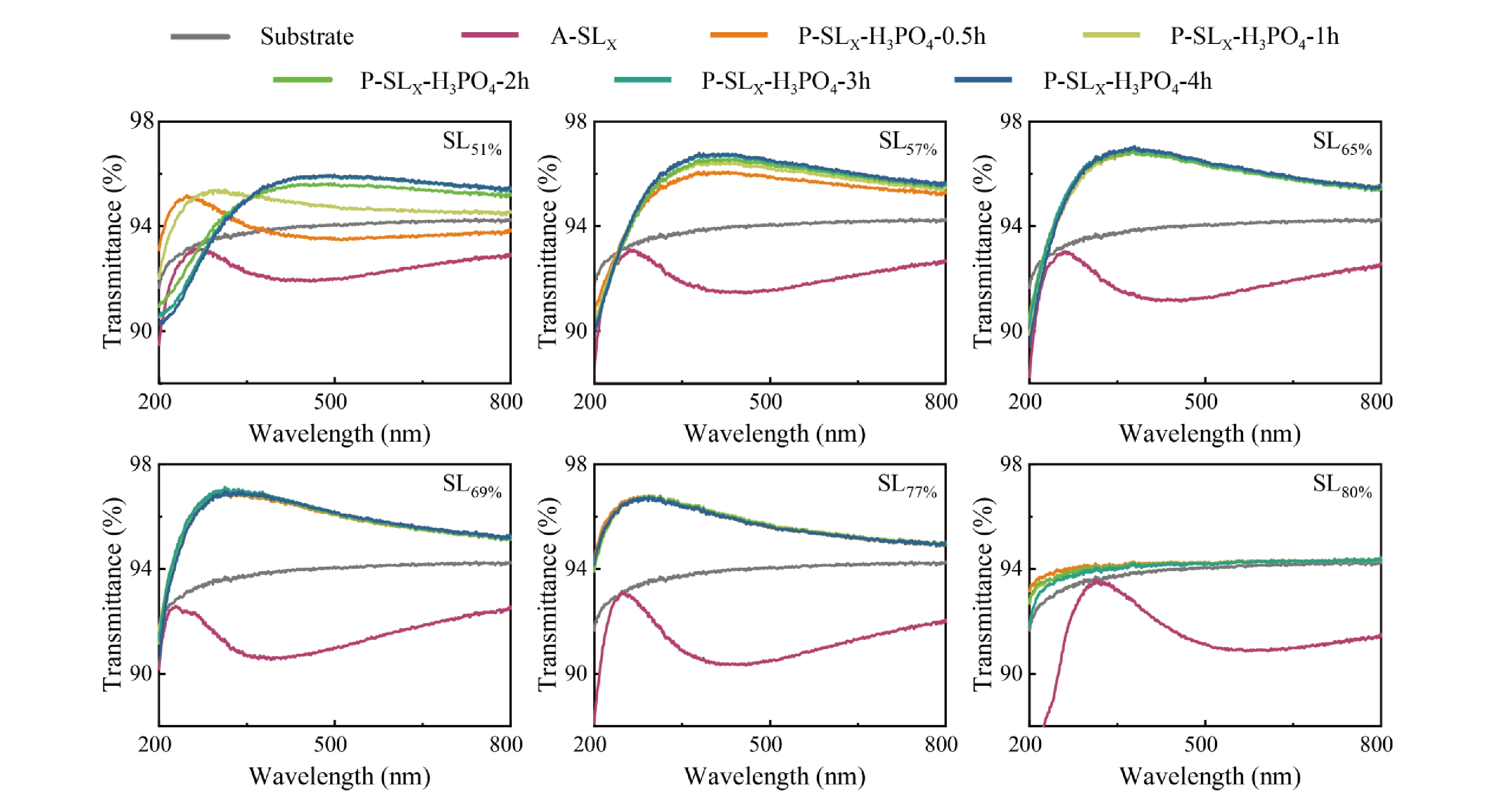
Fig. 2 Transmittance spectra of the as-deposited single-layer Al2O3–SiO2 mixture coatings, denoted as A-SLX, and the porous single-layer SiO2 coatings, denoted as P-SLX-H3PO4-T.
The refractive index dispersion curves and layer thicknesses of A-SLX and P-SLX-H3PO4-T were fitted according to the transmittance spectra. As shown in Fig. 3a, b, an increase in the Al element ratio was correlated with an increase in the n value (at a wavelength of 355 nm) of the mixture coating, while both the n value and thickness of the porous coating decreased. Notably, when the Al element ratio reached 80% or higher, a marked reduction in the layer thickness after etching was observed. Scanning electron microscopy (SEM) images shown in Fig. 3c reveal an obvious microporous structure at an elevated Al content. The surface morphologies of the Al2O3–SiO2 mixture coatings and porous coatings were characterized using atomic force microscopy (AFM), and the root-mean-square (RMS) surface roughness of the coatings was computed using AFM software, as shown in Fig. 3d. The RMS values of the Al2O3–SiO2 mixture coatings decreased with increasing Al element ratio. The RMS value of the porous coating was slightly higher than that of the corresponding mixture coating. Notably, the RMS value of P-SL80%-H3PO4-3h was significantly higher than that of the other samples. This may be attributed to the unstable SiO2 grid structure that remains after a substantial amount of Al2O3 is removed, leading to an additional loss of SiO2 material during etching and cleaning, ultimately resulting in a reduced amount of SiO2 being retained on the substrate surface.
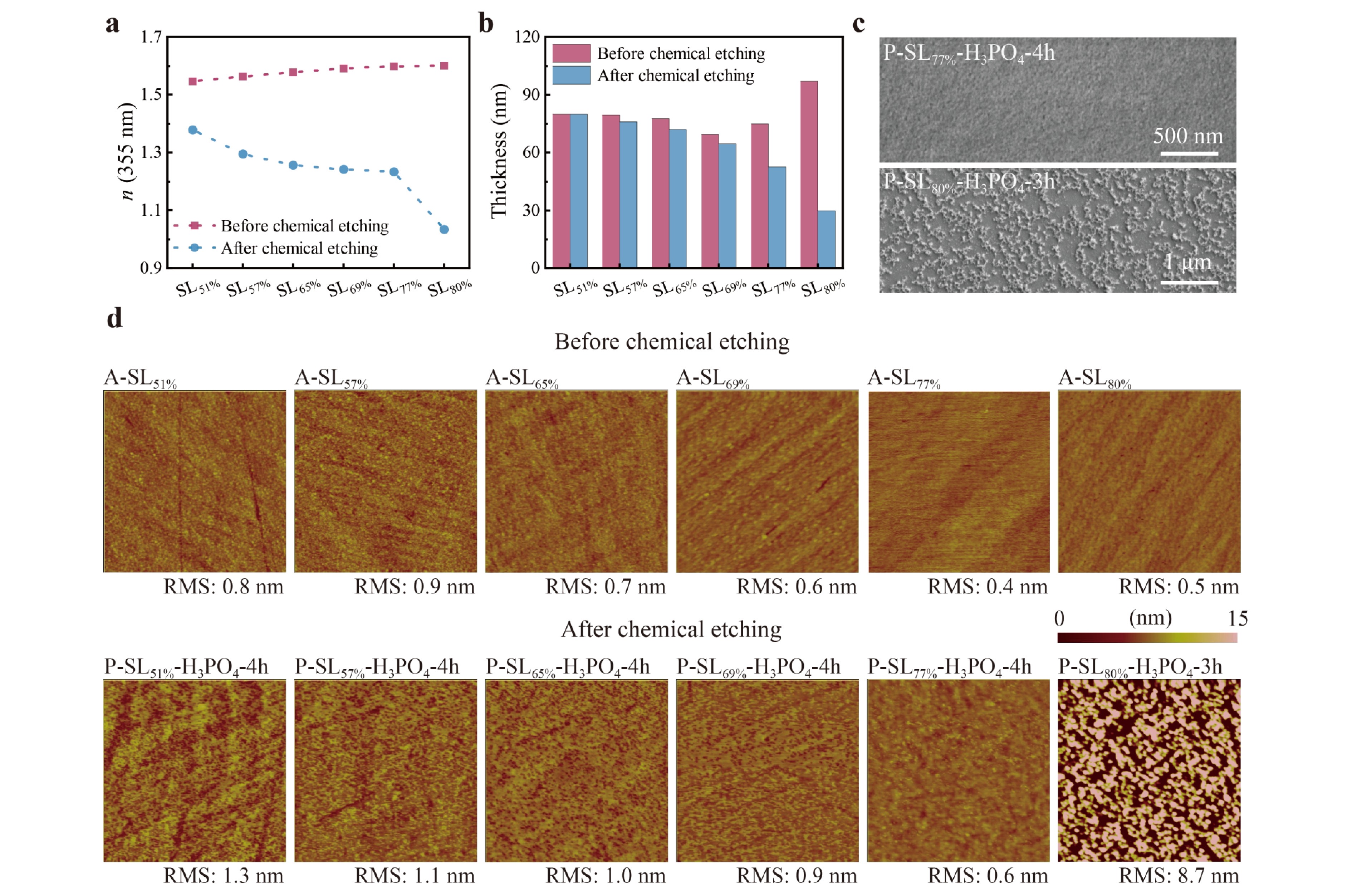
Fig. 3 Properties of the as-deposited single-layer Al2O3–SiO2 mixture coatings A-SLX and the porous single-layer SiO2 coatings P-SLX-H3PO4-T. a n value (at a wavelength of 355 nm). b Thickness. c Scanning electron microscopy (SEM) images of P-SL77%-H3PO4-4h and P-SL80%-H3PO4-3h. d Atomic force microscopy (AFM) images along with root-mean-square (RMS) values.
In addition to the H3PO4 solution, an HNO3 solution was used to prepare porous single-layer SiO2 coatings, denoted as P-SLX-HNO3-T. Once the sample was removed from the acid solution and exposed to air, surface cracks developed on the coating during solvent evaporation (Fig. 4a). This phenomenon may be associated with the high capillary pressure gradient during the drying process34. Notably, the etching time did not significantly affect the appearance of surface cracks, probably because most of the Al2O3 was removed after 1 h of etching, rendering subsequent increases in etching duration ineffective in altering the coating structure. X-ray photoelectron spectroscopy (XPS) results are shown in Fig. 4b; evidently, the Al element content decreased to approximately 2.5% after 1 h of etching. To address the surface-cracking issue, a surface modification process was carried out after etching, using a mixed solution of n-hexane and hexamethyldisilazane (HMDS). As illustrated in Fig. 4c, d, this surface-modification technique effectively prevented the formation of cracks in the porous SiO2 coating. However, this process may generate residual organic substances and decrease the LIDT of the coating. According to the experimental results reported by Chen et al.35, after modifying the sol-gel SiO2 coating using an ammonia-HMDS atmosphere, the LIDT of the coating decreased from 24.3 J/cm2 to 19.4 J/cm2. The transmittance spectra, refractive index dispersion curves, and layer thicknesses of the coatings are shown in Fig. 4e-g, respectively. After 1 h of etching, the n value decreased from 1.564 to 1.299, accompanied by a thickness reduction of approximately 7%, from 747 nm to 693 nm. Increasing the etching time to 12 h resulted in a further slight decrease in the n value to 1.288, while the thickness decreased to 683 nm. However, extending the etching time to 36 h did not significantly alter the n value, though the thickness continued to decrease, reaching 674 nm. Compared with H3PO4, HNO3 exhibited a higher removal efficiency for Al2O3 in thicker mixture coatings, likely due to differences in both the reaction rate and product solubility. Specifically, HNO3 possesses stronger acidity, etches effectively at room temperature without heating, and produces highly soluble reaction species, while by-products with limited solubility formed in H3PO4 may slightly retard the reaction progress36.
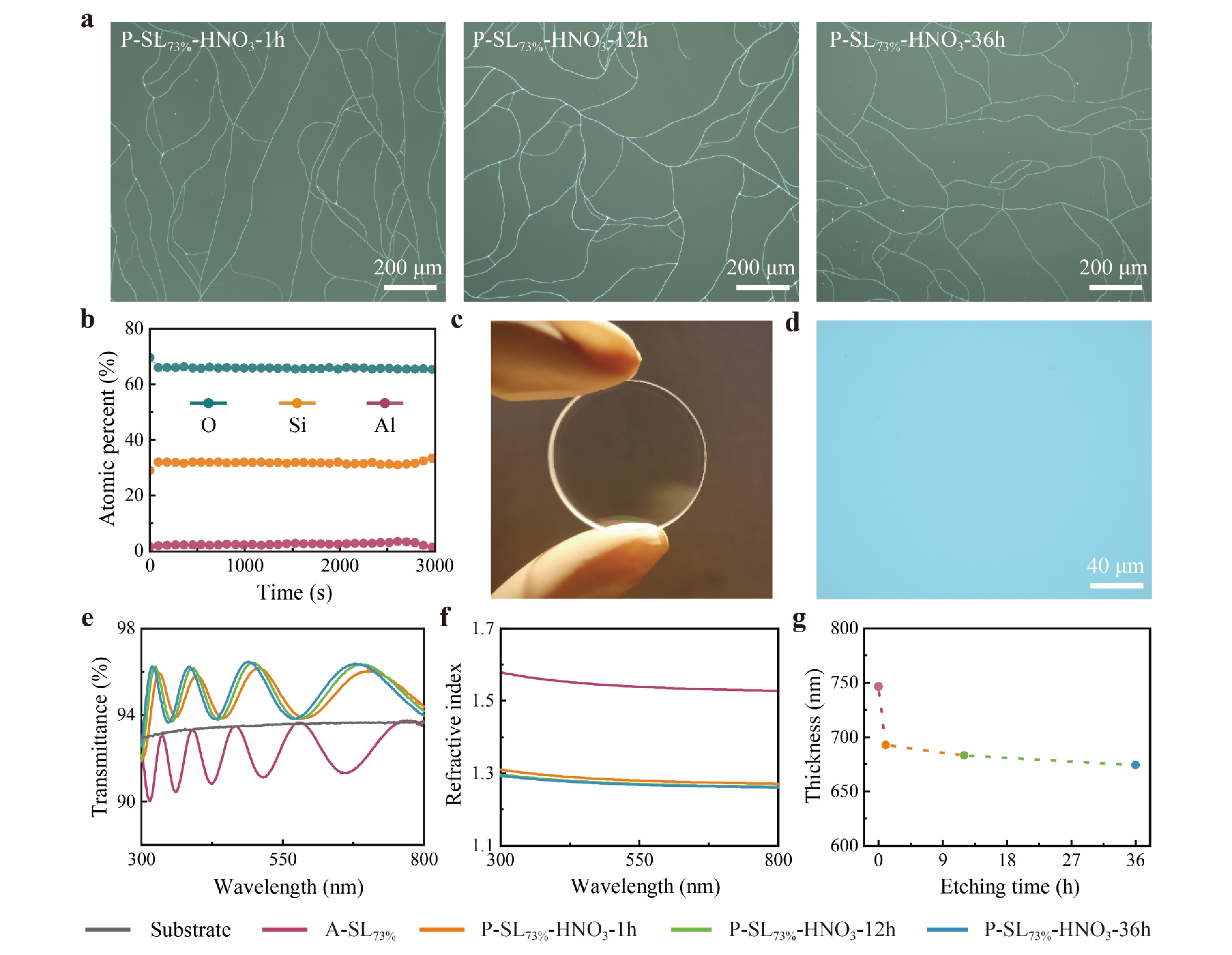
Fig. 4 Properties of the as-deposited single-layer Al2O3–SiO2 mixture coatings, denoted as A-SL73%, and the porous single-layer SiO2 coatings, denoted as P-SL73%-HNO3-T. a Optical microscopy images of surface cracks of P-SL73%-HNO3-T. b Elemental percentage profiles of P-SL73%-HNO3-1h. c Photograph and d optical microscopy images of P-SL73%-HNO3-12h after surface modification. e Transmittance spectra. f Refractive index dispersion curve. g Thickness.
Etching with the HNO3 solution achieved a faster etching rate than using the H3PO4 solution without heating, making it more applicable for large-size or multilayer Al2O3–SiO2 mixture coatings. An Al2O3–SiO2 mixture coating with an Al element ratio of 73% was deposited on a fused silica substrate measuring 200 mm × 120 mm × 30 mm. The sample was then etched in a 36% HNO3 solution for 12 h. Fig. 5a shows an image of the etched sample. Transmittance measurements were performed at 15 points uniformly distributed across the coating, and the locations of the test points, fitted n values (at a wavelength of 355 nm), and fitted layer thicknesses are shown in Fig. 5b-d, respectively. The refractive index and thickness uniformity of the porous coating were better than ±1%, and the thickness uniformity could be further improved using a shadowing mask.
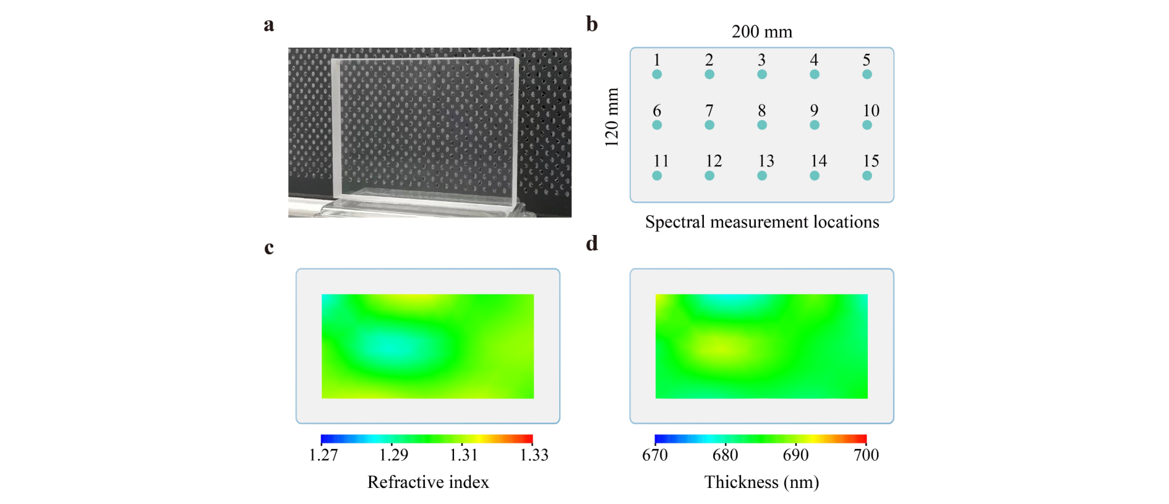
Fig. 5 Properties of the porous SiO2 coating on a large-size fused silica substrate. a Photograph of the large-size optics. b Schematic of spectral measurement locations. c Refractive index uniformity and d thickness uniformity of the porous coating.
-
An HR coating with the structure of substrate|HS(HLHR)25H|air was designed to achieve a reflectivity exceeding 99% at 355 nm with an intended incidence angle of 38°. Here, HS and H represent the SiO2 layers deposited under different process parameters, with thicknesses of 141.8 nm and 70.9 nm, respectively. LHR refers to a nanoporous SiO2 layer with a thickness of 83.6 nm. Compared with NO3−, SO42− has a lower UV absorption cross-section37,38. When acid solution residues are present in porous coatings, SO42− residues exhibit less absorption, potentially resulting in a smaller negative impact on the LIDT of the porous coatings. Consequently, H2SO4 was chosen as the acid solution for comparison with the coatings prepared using HNO3. Both types of HR coatings were etched for 36 h in their respective acid solutions to ensure complete removal of all Al elements from the Al2O3–SiO2 layers. The as-deposited HR coatings are denoted as A-HR, while the porous HR coatings etched with HNO3 and H2SO4 are denoted as P-HR-HNO3-36h and P-HR-H2SO4-36h, respectively.
Fig. 6a shows the reflectivity spectra of the porous coatings measured at a 38° incidence angle under s-polarized light. At 355 nm, the reflectivity of P-HR-HNO3-36h and P-HR-H2SO4-36h was 98.5% and 99.3%, respectively. These spectra were measured in the central region of the samples, indicating that a sufficient chemical reaction occurred in this area. This is because the pure SiO2 layer deposited under the process conditions adopted in this work has a relatively low packing density, providing pathways for the acid solution to penetrate from the surface toward the substrate. As shown in Fig. 6b, the absorption of A-HR decreased with increasing laser irradiation time, stabilizing at approximately 115 ppm after 150 s. In contrast, the absorption of both porous coatings remained relatively constant with the laser irradiation time, approaching approximately 10 ppm, similar to that of the fused silica substrate. Unlike traditional HR coatings, this all-silica structure avoids high-n materials with relatively low optical bandgaps, such as HfO2, resulting in significantly lower absorption under UV laser irradiation. Laser damage probability was evaluated in the 1-on-1 mode in accordance with ISO 21254 guidelines. An s-polarized 3ω Nd:YAG laser, operating at a pulse width of 8.2 ns, served as the light source, with damage detection performed via CCD imaging. Fig. 6c illustrates the laser damage probabilities of the two porous coatings as a function of laser fluence at an angle of 38°. Notably, P-HR-H2SO4-36h exhibited a lower damage probability than P-HR-HNO3-36h under identical laser fluences, indicating superior laser resistance. Focused-ion-beam scanning electron microscopy (FIB-SEM) images shown in Fig. 6d-l reveal the typical laser-induced damage morphologies of both porous coatings. Two distinct damage types were observed: flat-bottom pits and nodule-related pits. Unlike conventional HR coatings, no evidence of material melting was observed12. Additionally, microcracks were present in most damage pits, suggesting a relationship between laser-induced damage and coating stress. Initially, the damage appeared as flat-bottom pits, while nodule-related pits manifested at higher irradiation fluences. Cross-sectional analysis confirmed that the flat-bottom pits were associated with the porous SiO2 layer, as shown in Fig. 6h, i.
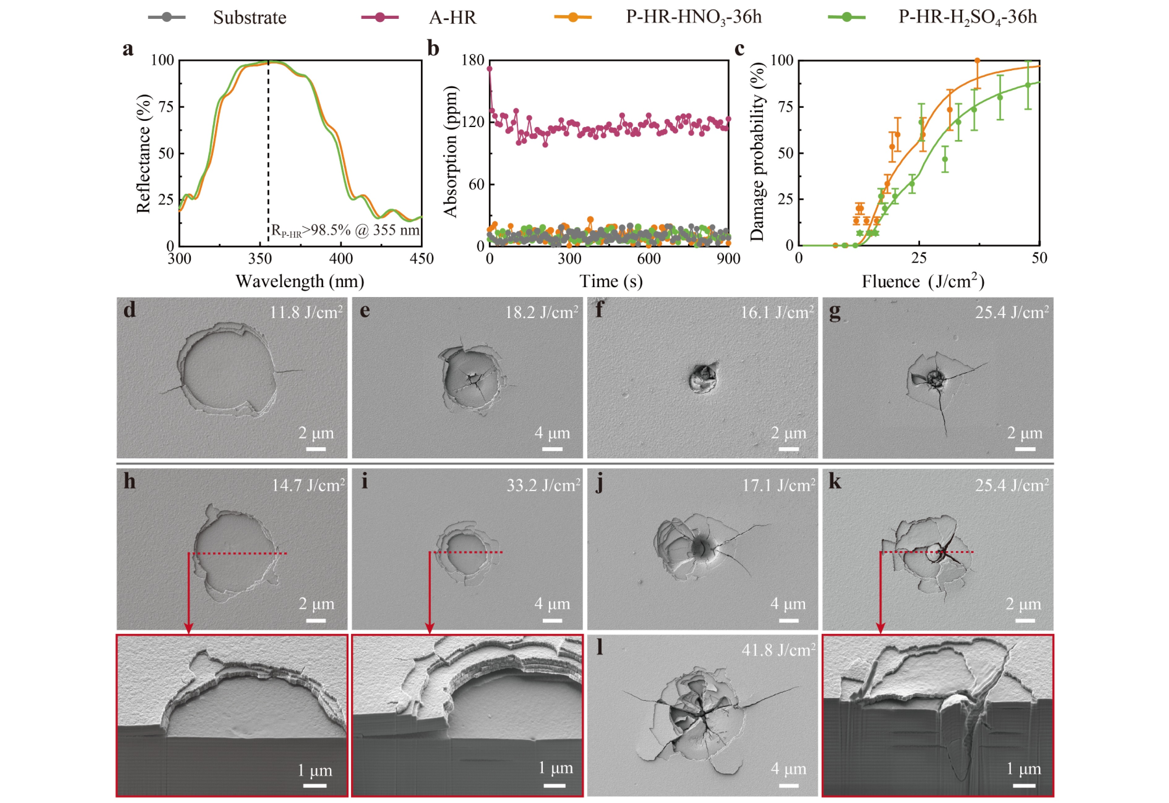
Fig. 6 Properties of A-HR, P-HR-HNO3-36h, and P-HR-H2SO4-36h. a Reflectance spectra. b Absorption versus testing time. c Laser-induced damage probability curves. d-g SEM images of surface damage morphologies of P-HR-HNO3-36h. h-l SEM images of surface and cross-sectional damage morphologies of P-HR-H2SO4-36h.
The damage probability curves of the two porous coatings were further analyzed using the model developed by Krol et al39. Based on the observed damage morphologies, two types of defects were identified: absorptive defects and nodules, each characterized by different LIDT values (Ti) and area densities (Di, integrated over the thickness). As summarized in Table 1, P-HR-H2SO4-36h exhibited a slightly higher LIDT and lower defect densities for both defect types than P-HR-HNO3-36h. Flat-bottom pits originating from the porous SiO2 layer were first observed under low-fluence laser irradiation, indicating that the absorptive defects within this layer are the primary factor limiting the LIDT of the HR coatings, while its defect density and LIDT can be influenced by the etching process.
D1 (mm−2) T1 (J/cm2) ∆T1 (J/cm2) D2 (mm−2) T2 (J/cm2) ∆T2 (J/cm2) P-HR-HNO3-36h 11.5 13.8 2.5 32.0 20.2 4.0 P-HR-H2SO4-36h 7.0 14.2 2.5 20.0 20.5 4.0 Notes. Di, Ti, and ∆Ti represent the defect density, threshold mean value, and threshold standard deviation, respectively. Table 1. Defect parameters extracted from laser-induced damage curves
The as-deposited coating A-HR and porous coating P-HR-H2SO4-36h, which demonstrated higher LIDT, were further examined. Fig. 7a presents images of the two coatings. Elemental composition was analyzed at the center region of the sample using XPS and Energy-dispersive spectroscopy (EDS). In the XPS analysis, 2 keV Ar+ ions were employed to etch P-HR-H2SO4-36h to a depth of approximately 1.8 μm, with the energy spectrum recorded every 90 s. During this process, the Al element content remained consistently low, and no distinct peak was observed in the Al 2p spectra; only background noise was present, as shown in Fig. 7b, c. Similarly, EDS detected no Al element in any layer of P-HR-H2SO4-36h, as illustrated in Fig. 7d. These results confirm the complete removal of Al2O3 from each Al2O3–SiO2 layer by chemical etching in the H2SO4 solution, resulting in an all-silica UV HR coating. The surface roughness increased slightly, from 3.6 nm to 3.9 nm, after etching (Fig. 7e). Fig. 7f shows the change in surface profile: A-HR displayed a convex profile, while P-HR-H2SO4-36h exhibited a concave profile. This shift towards a concave shape suggests that the porous SiO2 layer was under tensile stress, which could explain the microcracks observed in the laser damage morphologies. Under multi-pulse laser irradiation, the cyclic accumulation of thermal and mechanical stress may exacerbate coating fracture, leading to more severe damage. Given that coating stress is related to porosity and pore radius40, it can be mitigated by adjusting the co-evaporation parameters or implementing an appropriate annealing protocol41 to suit various laser application scenarios.
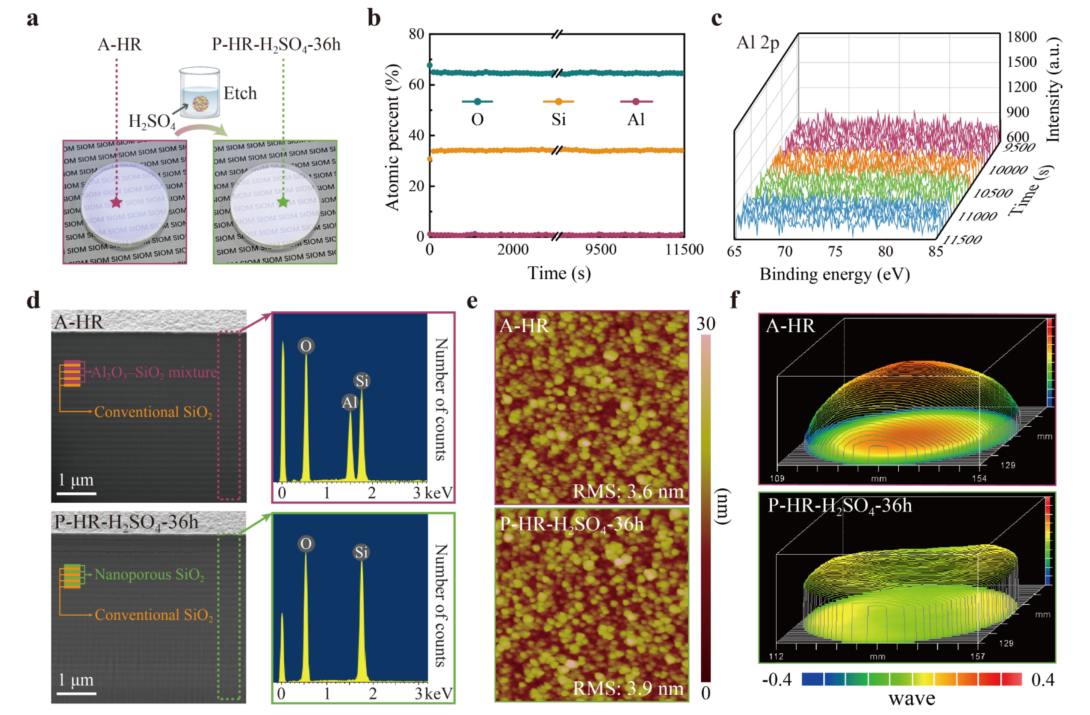
Fig. 7 Properties of A-HR and P-HR-H2SO4-36h. a Photographs. b Elemental percentage profiles of P-HR-H2SO4-36h. c X-ray photoelectron spectroscopy (XPS) spectra of Al 2p for P-HR-H2SO4-36h. d Cross-sectional morphologies and energy-dispersive spectroscopy (EDS) characterized chemical composition. e AFM characterized morphologies and RMS surface roughness values. f Surface profile figures.
-
An AR coating with the structure of substrate|LAR|air was designed to achieve a reflectivity below 0.15% at 355 nm. Here, LAR refers to a nanoporous SiO2 layer with a designed thickness of 70 nm. Considering that the porous HR coating prepared by etching in H2SO4 solution exhibited superior spectral performance and a higher LIDT than that prepared by etching in HNO3 solution, H2SO4 solution was used to prepare porous AR coatings with an etching duration of 4 h. The as-deposited and porous coatings are denoted as A-AR and P-AR-H2SO4-4h, respectively.
The transmittance and reflectance spectra of A-AR and P-AR-H2SO4-4h were compared with those of the fused silica substrate, as shown in Fig. 8a, c, respectively. The n value and thickness of A-AR were fitted to be 1.581 and 80.9 nm, while those of P-AR-H2SO4-4h were fitted to be 1.255 and 72.2 nm, respectively. P-AR-H2SO4-4h exhibited a notable anti-reflective effect with a reflectivity of approximately 0.08% at 355 nm, as shown in Fig. 8c. The RMS roughness values of A-AR and P-AR-H2SO4-4h were both approximately 0.9 nm, as shown in Fig. 8d. Fig. 8e shows the absorption of the coatings at 355 nm over testing time. The average absorption of A-AR was approximately 22 ppm, which decreased to approximately 10 ppm after etching, similar to that of the fused silica substrate.
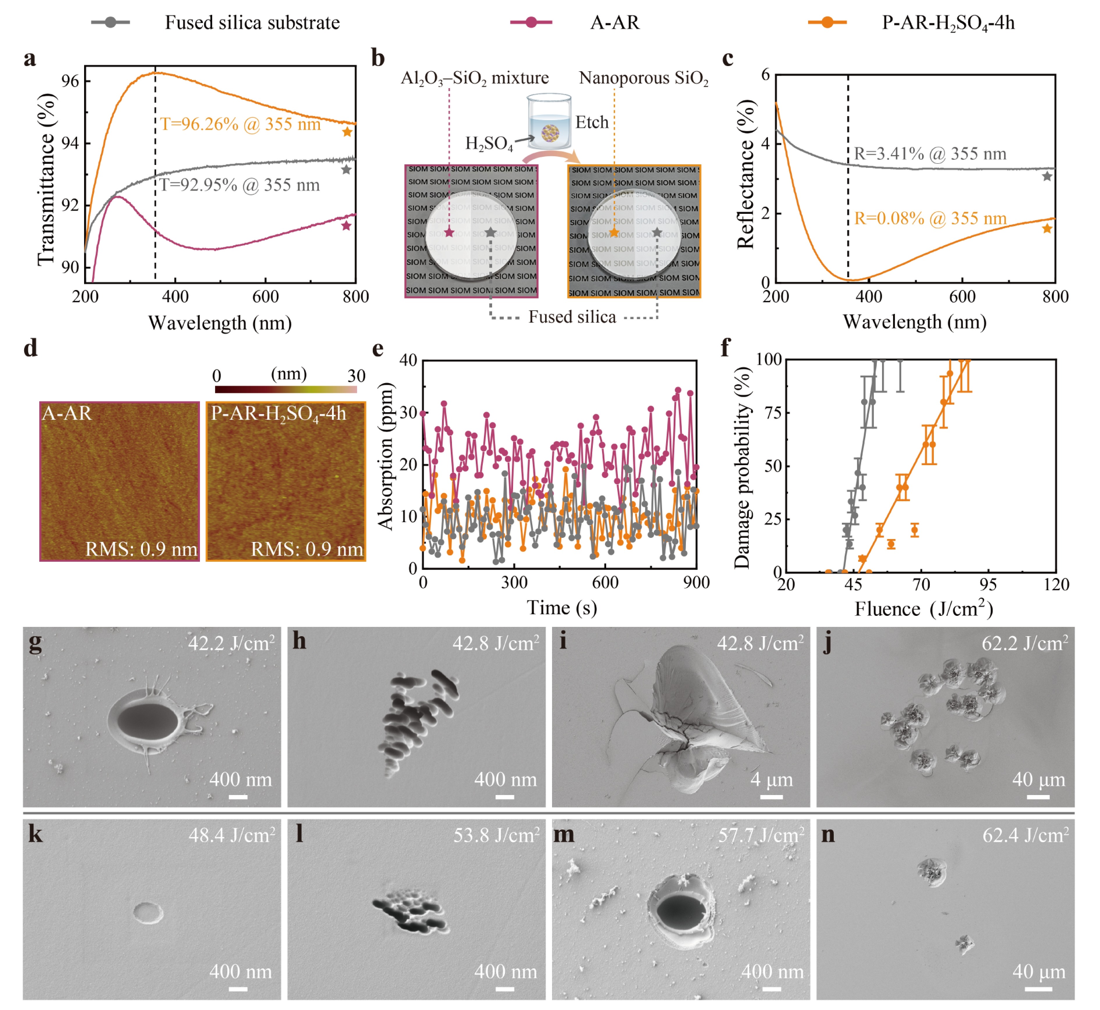
Fig. 8 Properties of A-AR and P-AR-H2SO4-4h. a Transmittance spectra. b Schematic of the etching process. c Reflectance spectra. d AFM characterized morphologies and their RMS surface roughness values. e Absorption versus testing time. f Laser-induced damage probability curves. SEM images of surface damage morphologies of g-j the silica substrate and k-n P-AR-H2SO4-4h.
The 1-on-1 LIDT was determined using a 3ω Nd:YAG laser (355 nm, 8.2 ns) as the light source, with the laser incident at an angle of 23°, the minimum achievable angle on our measurement platform. Fig. 8f shows the laser damage probabilities as a function of laser fluence for the porous coating and fused silica substrate; the linear fit of the LIDT for P-AR-H2SO4-4h was 46.9 J/cm2, surpassing the substrate’s LIDT of 41.1 J/cm2. The improved laser resistance of the porous AR coating compared to that of the substrate may be attributed to its lower absorption, as well as its nanoporous structure which likely facilitates more efficient energy relaxation. The damage morphologies of the fused silica substrate and P-AR-H2SO4-4h are shown in Fig. 8g-n. Typical damage features of the substrate included pinpoint pits (Fig. 8g), ripple-like damage (Fig. 8h), and craters (Fig. 8i). In contrast, P-AR-H2SO4-4h exhibited similar damage morphologies but with isolated flat-bottom pits (Fig. 8k) observed under near-LIDT laser irradiation. Under identical laser fluences, the density of craters in P-AR-H2SO4-4h was lower than that in the substrate (Fig. 8j, n), demonstrating that P-AR-H2SO4-4h provided better laser resistance than the fused silica substrate.
-
All-silica laser-resistant coatings, including UV AR and HR coatings, were fabricated using a combination of plasma-ion-assisted electron-beam co-evaporation of Al2O3–SiO2 mixtures and selective chemical etching. This unique all-silica coating method exhibited several key characteristics. First, complete removal of Al2O3 from the mixture was achieved by optimizing the Al2O3–SiO2 ratio and etching time, resulting in the formation of a low-n porous SiO2 layer. Notably, the absorption of this coating at 355 nm was comparable to that of the fused silica substrate. Second, the rapid etching rate provided by HNO3 or H2SO4 solutions enabled the preparation of large-size single-layer or multilayer coatings. The UV AR and HR coatings produced using the proposed technique exhibited good spectral properties and laser resistance at 355 nm. Specifically, the LIDT of the AR coating exceeded that of the fused silica substrate. Moreover, this cost-effective approach eliminated the need for expensive laser coating materials such as hafnium. In practical applications, porous coatings are prone to adsorbing moisture42 and organic contamination43–45, which adversely affect the optical stability and LIDT of the coatings. This issue may be addressed in the future by investigating anti-wetting and anti-fouling measures such as surface hydrophobic modification46 and non-destructive cleaning47. Therefore, this method holds great promise for widespread applications in advanced laser systems.
-
Seven single-layer Al2O3–SiO2 mixture coatings were deposited on double-side-polished fused silica substrates using a plasma-ion-assisted electron-beam co-evaporation process. Prior to loading into the vacuum chamber, the substrates underwent ultrasonic cleaning. Subsequently, the chamber was heated to 50 ℃ and evacuated to a base pressure below 9 × 10⁻⁴ Pa before deposition. Al2O3–SiO2 mixtures were deposited via the co-evaporation of Al2O3 and SiO2, with the deposition rates monitored by individual quartz crystal monitors positioned near each source. Plasma ion assistance was provided by an advanced plasma source (APS), operating in an Ar/O2 atmosphere at a pressure of approximately 4.9 × 10⁻² Pa. After deposition, the Al2O3–SiO2 mixtures were chemically etched in an acidic solution. The etched samples were rinsed with deionized water for at least 1 min and then soaked in anhydrous ethanol for at least 5 min. The detailed deposition and etching parameters of the Al2O3–SiO2 mixtures are listed in Table 2. Notably, the samples labeled P-SL73%-HNO3-T were immersed in a mixed solution of n-hexane and HMDS at a volume ratio of 4:1 for 2 h following chemical etching to prevent surface cracking.
Sample Deposition parameters Measured Al element ratio Al/(Al + Si) Sample Etching parameters APS bias voltage (V) Physical thickness (nm) Solution Temperature (℃) Time (h) A-SLX 100 70–100 51%, 57%, 65%, 69%, 77%, 80% P-SLX-H3PO4-T 85% H3PO4 50 0.5–4 A-SL73% 100 747 73% P-SL73%-HNO3-T 36% HNO3 room temperature 1, 12, 36 Table 2. Deposition and etching parameters for Al2O3–SiO2 mixture coatings and porous SiO2 coatings
-
As previously mentioned, an HR coating with a substrate|HS(HLHR)25H|air structure and an AR coating with a substrate|LAR|air structure were designed. The detailed design information is listed in Table 3. Notably, the LAR layer was deposited thicker than the designed thickness of 70 nm to compensate for the thickness reduction after etching. Single-side-polished fused silica was used as substrate for the reflectance measurements of the AR coatings, while double-side-polished fused silica was employed for all other measurements.
Sample Design information Deposition parameters Angle of
incidenceLayer Physical thickness
(nm)n
(355 nm)Ar/O2 atmosphere
(10−2 Pa)APS bias voltage
(V)Deposition rate (nm/s)
Al2O3/SiO2A-HR 38° HS 141.8 1.460 — — 0/0.2 H 70.9 1.460 3.9 90 0/0.4 LHR 83.6 1.265 4.9 90 0.14/0.1 A-AR 0° LAR 80.9 1.265 4.9 100 0.14/0.1 Table 3. Design specifications and deposition parameters for HR and AR coatings
The substrates for the HR coatings underwent ultrasonic cleaning, while those for the LIDT testing and AR coatings were cleaned using a buffered HF solution48. The detailed deposition and etching parameters of the HR and AR coatings are listed in Tables 3 and 4, respectively. The HR and AR coatings were etched for 36 h and 4 h, respectively, to achieve complete removal of Al2O3 from the mixture layer. The cleaning procedure following the chemical etching was consistent with that used for the P-SLX-H3PO4-T samples. Notably, this fabrication technique for nanoporous coating demonstrates good reproducibility. The HR and AR coatings, designed based on the parameters of the single-layer nanoporous coating, yield spectral measurement results that are all in line with design expectations.
Sample Etching parameters Solution Temperature (℃) Time (h) P-HR-HNO3-36h 36% HNO3 room temperature 36 P-HR-H2SO4-36h 36% H2SO4 room temperature 36 P-AR-H2SO4-4h 36% H2SO4 50 4 Table 4. Chemical etching parameters for HR and AR coatings
-
The transmittance spectrum was measured using a UV–VIS–NIR spectrometer (Perkin Elmer Lambda 1050), and the reflectance spectrum was derived from the transmittance data, neglecting absorption. Based on the iterative genetic algorithm simulation method, the refractive index dispersion curves and layer thicknesses were fitted according to the measured transmittance spectra49. The spectra used for fitting ranged from λ1 (300 nm) to λ2 (800 nm). The variance (Tv) between the fitted and measured transmittance values served as the evaluation function, with a target variance of 10−9.
$$ {\text{T}}_{\text{v}}\text=\frac{\text{1}}{{\text{λ}}_{\text{2}}\,-\,{\text{λ}}_{\text{1}}}\int \limits_{{\text{λ}}_{\text{1}}}^{{\text{λ}}_{\text{2}}}{\left({\text{T}}_{\text{M}}\left(\text{λ}\right)\,-\,{\text{T}}_{\text{S}}\left(\text{λ}\right)\right)}^{\text{2}}\text{dλ} $$ where TM(λ) and TS(λ) represent the fitted and measured transmittance values at wavelength λ, respectively. The surface profile of the coating was characterized using an optical interferometer (ZYGO Mark Ⅲ-GPI) in a controlled environment with a temperature of 23 ± 1.5 ℃ and relative humidity of 45% ± 5%. The absorption at 355 nm was measured using a custom system based on the surface thermal lensing technique50. The RMS roughness was measured using AFM (Veeco Dimension 3100) over a 5 μm × 5 μm area in tapping mode for each coating. The post-etch surface morphologies were examined using an optical microscope (Carl Zeiss Axioscope 5). The chemical compositions of the coatings before and after chemical etching were analyzed by XPS (Thermo Scientific K-Alpha). The LIDT was tested in 1-on-1 mode in accordance with ISO 21254 guidelines, using an s-polarized 3ω Nd:YAG laser with an 8.2 ns pulse width as the light source. The effective beam size was approximately 0.22 mm2, and 15 sites were tested for each laser fluence. Surface and cross-sectional damage morphologies were characterized by FIB-SEM (Carl Zeiss AURIGA CrossBeam). The elemental composition of one layer of the multilayer coating was analyzed using EDS (Oxford X-Max).
-
This work was supported by the Program of Shanghai Academic Research Leader (23XD1424100), CAS Project for Young Scientists in Basic Research (YSBR-081), Shanghai Leading Talent Program, and National Natural Science Foundation of China (61975215). The authors express their appreciation to Dr. Jian Sun and Mr. Longsheng Wang for their assistance in sample preparation, to Prof. Dawei Li for absorption measurements, and to Prof. Yuan’an Zhao and Mrs. Ziyuan Xu for LIDT measurements.
Advanced nanoporous SiO2 coatings for ultraviolet laser-resistant high-reflection and anti-reflection optics
- Light: Advanced Manufacturing , Article number: 41 (2026)
- Received: 30 July 2025
- Revised: 17 March 2026
- Accepted: 18 March 2026 Published online: 25 May 2026
doi: https://doi.org/10.37188/lam.2026.041
Abstract: Laser-resistant coatings are becoming increasingly essential to meet the growing demand for high-power lasers. The laser-induced damage threshold (LIDT) of coatings can be significantly improved by constructing dielectric coatings that contain both high-refractive-index (high-n) and low-n layers made from SiO2-based materials with a wide bandgap and low absorption, specifically dense and porous SiO2. This study proposes and demonstrates the fabrication of all-silica laser-resistant anti-reflection (AR) and high-reflection (HR) coatings using a combination of plasma-ion-assisted electron-beam co-evaporation of Al2O3–SiO2 mixtures, followed by selective chemical etching. The suitability of this method for producing large-size single-layer and multilayer coatings was verified experimentally. The porous SiO2 layer exhibited absorption properties comparable to those of a fused silica substrate. Both AR and HR coatings exhibited good laser resistance at a wavelength of 355 nm. Notably, the LIDT of the AR coating (~46.9 J/cm2) exceeded that of the fused silica substrate (~41.1 J/cm2). The proposed fabrication method is simple, cost-effective, and holds great promise for advancing the development of high-performance laser coatings.
Research Summary
Ultraviolet laser-resistant optics: Advanced nanoporous SiO2 coatings
An advanced preparation method for all-silica laser-resistant coating holds great potential for broad application in laser systems. The “all-silica” strategy, where both high-refractive-index (dense) and low-refractive-index (porous) layers are SiO2 materials with a large bandgap and low absorption loss, has proven effective in improving laser resistance. However, prior demonstrations of this method have faced challenges such as non-uniformity or cracking when applied to large-scale or multilayer coatings. Now, Meiping Zhu and her colleagues from the Shanghai Institute of Optics and Fine Mechanics, Chinese Academy of Sciences, have introduced a novel fabrication method for all-silica coatings that combines plasma-ion-assisted electron-beam co-evaporation with chemical etching. Experiments have confirmed the suitability of this method to produce large-size or multilayer coatings. The ultraviolet anti-reflection and high-reflection coatings fabricated using this strategy exhibit excellent spectral performance and laser resistance.
Rights and permissions
Open Access This article is licensed under a Creative Commons Attribution 4.0 International License, which permits use, sharing, adaptation, distribution and reproduction in any medium or format, as long as you give appropriate credit to the original author(s) and the source, provide a link to the Creative Commons license, and indicate if changes were made. The images or other third party material in this article are included in the article′s Creative Commons license, unless indicated otherwise in a credit line to the material. If material is not included in the article′s Creative Commons license and your intended use is not permitted by statutory regulation or exceeds the permitted use, you will need to obtain permission directly from the copyright holder. To view a copy of this license, visit http://creativecommons.org/licenses/by/4.0/.

 DownLoad: