


HTML
-
Real-time, high-resolution in vivo imaging is essential for biomedical diagnosis and minimally invasive therapy1,2. Such imaging enables microvascular perfusion mapping3 and image-guided interventions such as targeted biopsy4 and stent placement5. Conventional lens-based endoscopes have been widely employed for examining luminal organs; however, the inherent rigidity and trade-off between flexibility and resolution restrict these endoscopes from accessing confined regions, such as the deep brain or cardiovascular tissues6−9. To address these limitations, fiber-optic imaging has emerged as an active and rapidly evolving research frontier, with recent advances spanning single-mode fiber10,11, multimode fiber imaging12−22, and multi-core fiber (MCF) imaging23−28. To make imaging systems more compact, lensless architectures have been applied, offering the advantage of eliminating distal optics and thereby reducing the size and weight of the system29−31. In particular, lensless MCF imaging enables distal endoscope tips with a few hundred micrometers in diameter, maintaining imaging stability against fiber bending and environmental perturbations32−40. Nevertheless, the intrinsic spacing between MCF cores imposes a fundamental sampling limit. While each core effectively integrates the incident light within its numerical aperture (NA) to act as a spatial low-pass filter, the object's spatial frequencies often exceed the maximum resolvable frequency defined by the inter-core spacing. Consequently, this discrete-sampling lattice inevitably leads to undersampling of the object field, thereby violating the Nyquist–Shannon theorem and resulting in spectral aliasing that manifests itself as pronounced honeycomb artifacts.
Traditional approaches to suppress MCF honeycomb artifacts employed filtering and interpolation, such as morphological closing combined with Fourier-domain peak correction and Gaussian notch filtering41. These methods are computationally efficient, but yield only modest improvements over raw acquisitions. More advanced algorithms exploit multi-frame fusion42, maximum a posteriori (MAP) estimation43, and spatial pixel-shift integration44 to reduce honeycomb artifacts and enhance the image resolution simultaneously. These approaches enhance the image quality but require significant computational costs. Optical strategies can also be employed to mitigate imaging artifacts. By using the MCF as a “fiber lens” placed away from the image plane, honeycomb artifacts can be significantly reduced or eliminated37,45. This approach mitigates artifacts that are caused by sampling but introduces ghost replicas from higher diffraction orders. Suppression of these higher orders is necessary to achieve a large field of view. One effective strategy is employing femtosecond laser pulses. However, this method requires considerable technical effort to compensate for the inherent inter-core group delay dispersion46. Alternatively, higher-order replicas can be suppressed computationally using physics-informed neural networks or structurally by adopting a randomized core arrangement47.
In recent years, deep learning has become a powerful framework for fiber-optic imaging37,48−57. GARNN58, HAR-CNN59, and GAN-based methods60 have enabled the end-to-end removal of honeycomb artifacts in MCF imaging, facilitating real-time endoscopic applications. However, deep-learning-based methods still suffer from two key limitations that stem from their methodological design. First, most rely purely on data-driven approaches, without integrating physics-informed priors. Thus, their performance depends heavily on the quality and scale of the training datasets, which typically require tens of thousands of samples. However, acquiring such paired data using fiber-optic imaging is challenging. Existing methods use additional optical paths58 to acquire reference images, and each data acquisition set requires manual replacement of the imaging target, which is typically a biological tissue or sample, thereby significantly increasing the costs and difficulty. Second, some studies have used synthetic datasets to mitigate real data shortages59,60. However, this solution is flawed because synthetic data generation generally overlooks inter-core crosstalk, which is a critical physical phenomenon in MCF imaging. These two issues make it difficult to ensure the robustness of trained models when they are applied to different scenarios.
To address these challenges, we propose the Spectral-Guided Artifact Removal Network (SGARNet), which embeds a physics-informed prior into the bottleneck feature spectra through a lightweight mid-layer SpectralGate that is implemented as a learnable notch mask. A degradation model for lensless MCF imaging is first established to link honeycomb artifacts to the core geometry quantitatively. Guided by this model, SpectralGate is introduced to encode the frequency-domain characteristics, and the network is designed without explicit nonlinear activation functions, thereby streamlining the data flow and lowering the computational cost and latency. In addition, we develop a self-registered paired-dataset acquisition strategy for real MCF imaging without additional optical paths. Using only 2,800 paired samples, the network is trained within a supervised learning framework using a joint loss function and evaluated on images of diverse textural complexities. Experimental results demonstrate that SGARNet generalizes across different image complexities, suppresses honeycomb artifacts, and enables accurate full-color image restoration with an end-to-end processing speed of 10 images per second.
-
The honeycomb artifacts produced in MCF image transmission are closely related to the core arrangement at the facets as well as the fiber parameters. The most common packing geometries are square and hexagonal lattices. In this section, a physics model is established to analyze the influence of the core diameter and inter-core spacing on honeycomb artifacts under hexagonal packing.
In lensless MCF image transmission, each fiber core directly collects coupled incident light within the critical angle. As shown in Fig. 1, the transmitted image can be regarded as a local-weighted average of the input intensity, followed by convolution with the point spread function (PSF) of each fiber, resulting in a low-quality output image with honeycomb artifacts. The PSF of each fiber can be expressed in terms of the coupling efficiency at the fiber facet, and is commonly modeled as a Gaussian distribution61:
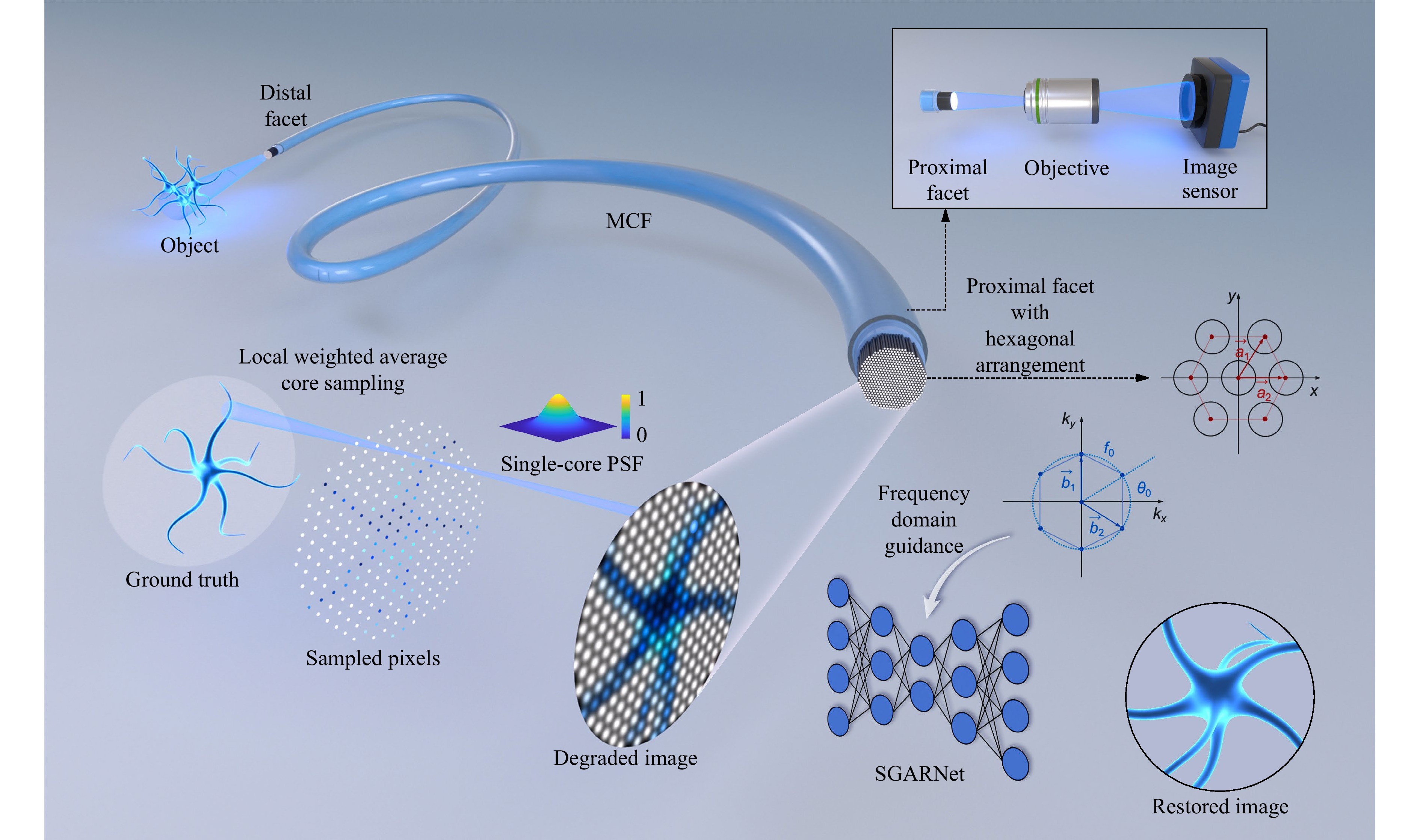
Fig. 1 Lensless MCF degradation mechanism and frequency-domain-guided SGARNet image restoration. MCF transmission process: Fiber cores sample the ground truth (GT) via locally weighted averaging; the sampled field is then convolved with the PSF of each core, yielding a degraded image with honeycomb artifacts. For the proximal facet with a hexagonal arrangement, $ a_1 $ and $ a_2 $ are the basis vectors in the spatial domain, whereas $ b_1 $ and $ b_2 $ are the corresponding basis vectors in the frequency domain; $ f_0 $ denotes the fundamental spatial frequency and $ \theta_0 $ is the angle between the first reciprocal-lattice vector and the $ k_x $-axis.
$$ {PS F} = \text{exp} \left(-\frac{\lvert \vec r \rvert^{2}}{2\sigma^{2}}\right) $$ (1) where $ \sigma $ denotes the standard deviation of the Gaussian distribution, and the weighting function at the input facet is expressed as
$$ G(\vec r_0) = \frac{1}{2{{\text{π}}} \sigma_c^{2}}\,\text{exp} \left(-\frac{\lvert \vec r_0 \rvert^{2}}{2\sigma_c^{2}}\right) $$ (2) where $ \vec r_0 $ is the position vector with the origin defined at the center of the distal facet plane perpendicular to the optical axis. $ {\sigma _c} $ is related to the fiber parameters. When the full width at half maximum of the Gaussian function is approximately equal to the core diameter, it can be expressed as
$$ \sigma _c = \sigma = \frac{d} {2\sqrt {2\ln 2}} $$ (3) For MCF with hexagonal packing, the center position of each fiber core can be expressed as
$$ {\vec r_{m,n}} = m{\vec a_1} + n{\vec a_2} $$ (4) where
$$ \left\{ \begin{array}{l} {\vec a_1} = l(1, 0) \\ {\vec a_2} = l\left( \dfrac{1}{2}, \dfrac{\sqrt{3}}{2}\right) \end{array} \right. $$ (5) are basis vectors, determined by the inter-core spacing $ l $. Then the output intensity distribution at the proximal facet can be expressed as
$$ Y(\vec r) = \sum\limits_{m,n} {[X(\vec r_0) * G(\vec r_0)]} \cdot \delta (\vec r_0 - {\vec r_{m,n}}) * {{PS F}} $$ (6) where * denotes convolution, $ X(\vec r_0) $ represents the ideal distribution of image information on the distal facet, and $ G(\vec r_0) $ is the weighting function. Eq. 6 captures the sampling effect introduced by MCF image transmission. The simulated degraded image using the proposed physics model and experimental parameters, including the core diameter $ d=2\; $µm and inter-core spacing $ l=3\; $µm, is presented in Fig. 2b. The resulting honeycomb artifacts closely match those observed in the experimentally acquired image shown in Fig. 2c. The influence of the fiber parameters $ l $ and $ d $ on the formation of honeycomb artifacts is then analyzed in the frequency domain.
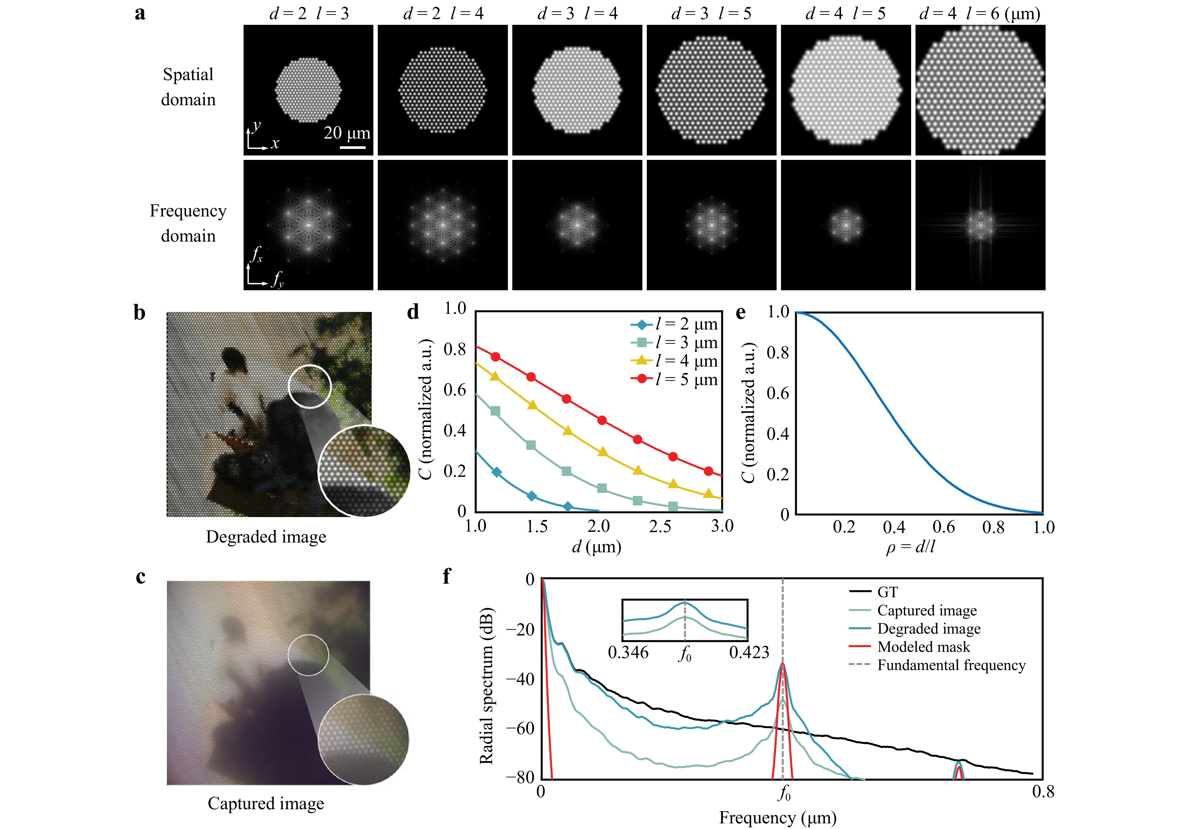
Fig. 2 Simulation and analysis of honeycomb artifacts in lensless MCF imaging: a Simulated artifacts under different core diameters $ d $ and inter-core spacings $ l $ in the spatial and frequency domains. b Simulated degraded image. c Experimentally acquired image. d, e Correlation coefficient $ C $ versus $ d $ and $ d/l $. f Azimuthally averaged radial spectra of the ground-truth, experimental, and simulated images, and the hexagonal lattice mask, each normalized individually; the gray dashed line indicates the fundamental frequency $ f_0 $.
In the frequency domain, the reciprocal-lattice vectors of the hexagonal core arrangement with lattice constant $ l $ are expressed as
$$ \left\{ \begin{array}{l} {\vec b_1} = \dfrac{{2{\text π} }}{l}\left(1, - \dfrac{1}{{\sqrt 3 }}\right)\\ {\vec b_2} = \dfrac{{2{\text π} }}{l}\left(0,\dfrac{2}{{\sqrt 3 }}\right) \end{array} \right. $$ (7) The optical transfer function (OTF) of a single fiber is approximated by a Gaussian function,
$$ H(f) = \exp ( - 2{{\text π} ^2}{\sigma ^2}{f^2}) $$ (8) where $ \sigma $ is related to the core diameter $ d $ as indicated in Eq. 3.
The fundamental spatial frequency of the hexagonal lattice is $ {f_0} = {|{{\vec b}_1}|}/{{2{\text π} }} = {2}/{({\sqrt 3 l})} $. Therefore, the inter-core spacing $ l $ primarily determines the spatial frequency of the honeycomb artifacts via its influence on the lattice frequencies. The sampling bandwidth increases as $ l $ decreases; thus, smaller values of $ l $ reduce the visibility of the artifacts. The core diameter $ d $ primarily affects the OTF through $ \sigma $. A larger $ d $ suppresses high spatial frequencies, leading to blurrier artifact edges and lower contrast, hence a less pronounced appearance. Since the dominant honeycomb pattern arises from the first ring of reciprocal-lattice frequencies with magnitude $ f_0 $, substituting $ f_0 $ and Eq. 3 into Eq. 8 yields the following expression for the artifact contrast:
$$ C \propto \text{exp} \left( - \frac{{{{\text π} ^2}}}{{3\ln 2}}\frac{{{d^2}}}{{{l^2}}}\right) $$ (9) As shown in Fig. 2a, the prominence of honeycomb artifacts is primarily related to the ratio of the core diameter $ d $ to the inter-core spacing $ l $. Given that $ l $ must physically exceed $ d $, a smaller $ d/l $ leads to higher artifact contrast and a more distinct honeycomb pattern, confirming that the artifact contrast can be expressed by Eq. 9. The curves in Fig. 2d, e further illustrate the influence of the fiber parameters on $ C $.
-
Hexagonal core layouts in MCF impose a periodic sampling pattern on the imaging plane, producing pronounced peaks at the reciprocal-lattice frequencies in the Fourier domain (Fig. 2f). To weaken these lattice peaks explicitly while preserving the broadband image content, we propose a physics-guided frequency-domain gate, termed SpectralGate, and integrate it into a lightweight U-Net framework.
SpectralGate SpectralGate constructs a soft mask $ M(u,v) $ at the fundamental reciprocal-lattice frequency $ f_0 $ along the six hexagonal orientations $ \theta_m=\theta_0 + m{\text π}/ 3\; (m=0,\cdots,5) $, and applies a learnable attenuation $ 1-\alpha M(u,v) $ in the Fourier domain. With Gaussian standard deviation $ \sigma>0 $, the mask is
$$ \begin{align} M(u,v) &= \text{Norm}\left\{ \sum_{m=\text{0}}^\text{5} \exp \left(-\frac{u^{2}+v^{2}+f_{\text{0}}^{2}}{2\sigma^{2}}\right) \right. \\ &\quad \left. \cosh \left[\frac{f_{\text{0}}\big(u\cos\theta_{m}+v\sin\theta_{m}\big)}{\sigma^{2}}\right] \right\} \end{align} $$ (10) where $ {\mathop{{\rm{Norm}}}\nolimits} ( \cdot {\rm{)}} $ denotes the normalization function, and $ (u,v) $ represents the normalized spatial frequencies in the fast Fourier transform (FFT) baseband. For a feature map $ X(x,y) $ with a Fourier transform $ \hat{X}(u,v) $, SpectralGate applies
$$ \hat Y(u,v)=\bigl[1-\alpha M(u,v)\bigr]\hat X(u,v) $$ (11) where $ 0\le \alpha \le \alpha_{\text{max}} $. The output is expressed as $ Y={\cal{F}}^{-1}\{\hat{Y}\} $, where $ {\cal{F}}\{\cdot\} $ represents the Fourier transform. This task-adaptive notch formulation attenuates the fundamental lattice peaks that are responsible for honeycomb artifacts while minimally disturbing the non-lattice frequencies.
SGARNet architecture We instantiate SpectralGate within a compact U-Net encoder-decoder, named SGARNet. Since the SpectralGate explicitly resolves global periodic artifacts in the frequency domain, we deliberately employ a U-Net backbone rather than computationally expensive Transformer architectures to efficiently extract hierarchical multi-scale features. The network is built from NAFBlocks62 that are equipped with simplified channel attention (SCA) and SimpleGate units, which offer high computational efficiency while capturing multi-scale contextual features. SpectralGate is inserted into the U-Net bottleneck layer as shown in Fig. 3, providing a resolution-aware cacheable mask without increasing the complexity.
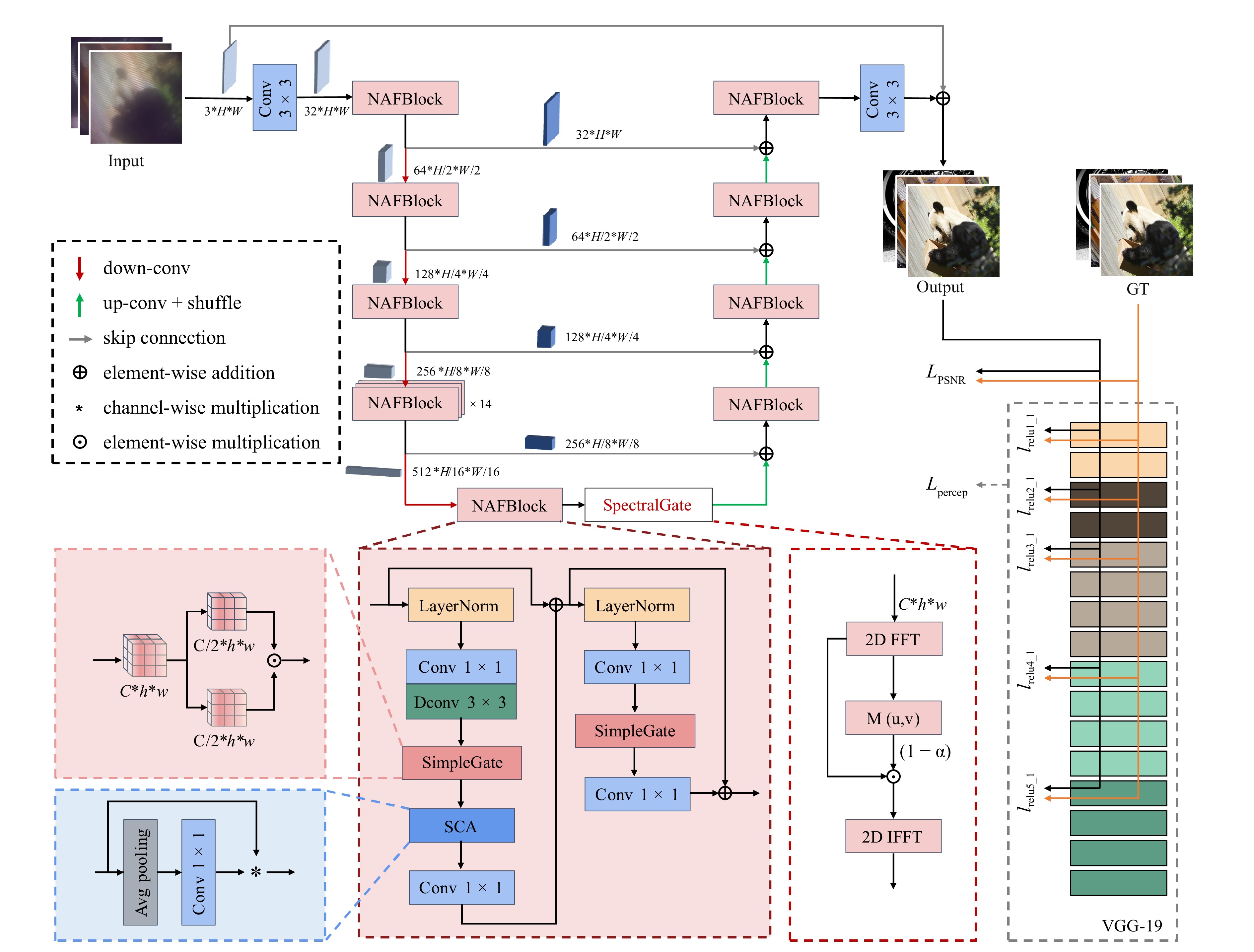
Fig. 3 Architecture of the proposed SGARNet. $ C $ denotes the number of channels, $ H $ and $ h $ denote the heights of the feature maps, $ W $ and $ w $ denote the widths of the feature maps.
Overview of NAFBlocks The primary role of nonlinear activation functions in neural networks is to break the limitation of linear superposition and provide the network with the capacity to represent complex mappings63. Conventional pointwise activations (e.g. ReLU and GELU) expand the spectra via self-convolution64, which can reinforce periodic components at the reciprocal-lattice locations and distort the amplitude distributions. In contrast, SimpleGate eliminates explicit pointwise activations and realizes nonlinearity through multiplicative channel interactions. The basic formulation of SimpleGate is expressed as
$$ Y = X_1 \odot X_2 $$ (12) where $ \odot $ denotes element-wise multiplication. This operation corresponds to the convolution of two sub-spectra in the frequency domain:
$$ {\cal{F}}\{ Y\} = {\cal{F}}\{ {X_1}\} * {\cal{F}}\{ {X_2}\} $$ (13) This promotes cross-channel frequency fusion rather than harmonic pile-up at the lattice frequencies, complementing the physics-guided suppression of SpectralGate.
Implementation and loss function Model training was conducted for 100,000 iterations with a batch size of 8. The optimizer used was AdamW, with an initial learning rate of $ 1\times10^{-3} $. To balance the pixel fidelity and structural consistency, the objective combined a pixel-level term and a VGG-based perceptual term,
$$ {{{\cal{L}}}_\text{total}} = {{{\cal{L}}}_{\text{PSNR}}} + {\lambda _p} \cdot {{{\cal{L}}}_{\text{percep}}} $$ (14) $ {\cal{L}}_{\text{PSNR}} $ represents the pixel-level loss and is defined as follows:
$$ {{{\cal{L}}}_{{\text{PSNR}}}} = \frac{{10}}{{\ln (10)}} \cdot \ln \left( {\frac{1}{N}\sum\limits_{i = 1}^N {{{\left( {I_{{\text{pred}}}^{(i)} - I_{{\text{gt}}}^{(i)}} \right)}^2}} + \varepsilon } \right) $$ (15) where $ I_\text{pred}^{(i)} $ and $ I_\text{gt}^{(i)} $ represent the predicted and GT intensity values at the $ i $-th pixel, respectively. $ N $ is the total number of pixels in an image, that is, $ N = C \times H \times W $ for an image with $ C $ channels, height $ H $, and width $ W $. $ \varepsilon $ is a small positive constant added to ensure numerical stability by avoiding the logarithm of zero. $ {\lambda _p} $ in Eq. 14 is the weight coefficient of the perceptual loss:
$$ {\cal{L}}_\text{percep} = \sum\limits_{j \in {\cal{J}}} \frac{1}{C_j H_j W_j} \left\| \phi_j (I_\text{pred}) - \phi_j (I_\text{gt}) \right\|_F^2 $$ (16) where $ \|\cdot\|_F $ denotes the Frobenius norm, and $ {\phi _j}( \cdot ) $ denotes the feature map extracted from the $ j $-th selected layer of a pre-trained VGG-19 network. $ C_j $, $ H_j $, and $ W_j $ are the number of channels, height, and width of the feature map in layer $ j $, respectively. In our implementation, $ {\cal{J}}= \{\text{relu1}\_\text{1},\; \text{relu2}\_\text{1},\; \text{relu3}\_\text{1},\; \text{relu4}\_\text{1},\; \text{relu5}\_\text{1}\} $, corresponding to the five selected VGG-19 layers used for feature extraction and perceptual loss computation, as shown in Fig. 3. This joint loss function enables the effective suppression of regular honeycomb patterns while preserving the tissue details and global structure.
-
We designed a self-registered paired-dataset acquisition method for lensless MCF imaging, with the experimental setup illustrated in Fig. 4. The GT images from the ImageNet dataset65 were displayed using a projector (DLPDLCR4710EVM-G2) featuring a digital micromirror device with a pixel pitch of 5.4 µm and a resolution of 1,920 × 1,080 pixels. The GT images were optically demagnified by the first objective lens (OBJ1: 50×, NA 0.55) and projected 30 µm away from the distal MCF facet37. The MCF (SUMITA HDIG) had an overall diameter of 350 µm and a length of 1,000 mm, containing approximately 10,000 cores with a core diameter $ d $ of 2 µm and an inter-core spacing $ l $ of 3 µm. The proximal facet was magnified by the second objective lens (OBJ2: 20×, NA 0.42) onto an industrial camera (GS3-U3-123S6C-C), which utilizes a sensor with a 3.45 µm pixel pitch and a resolution of 4,096 × 3,000 pixels.
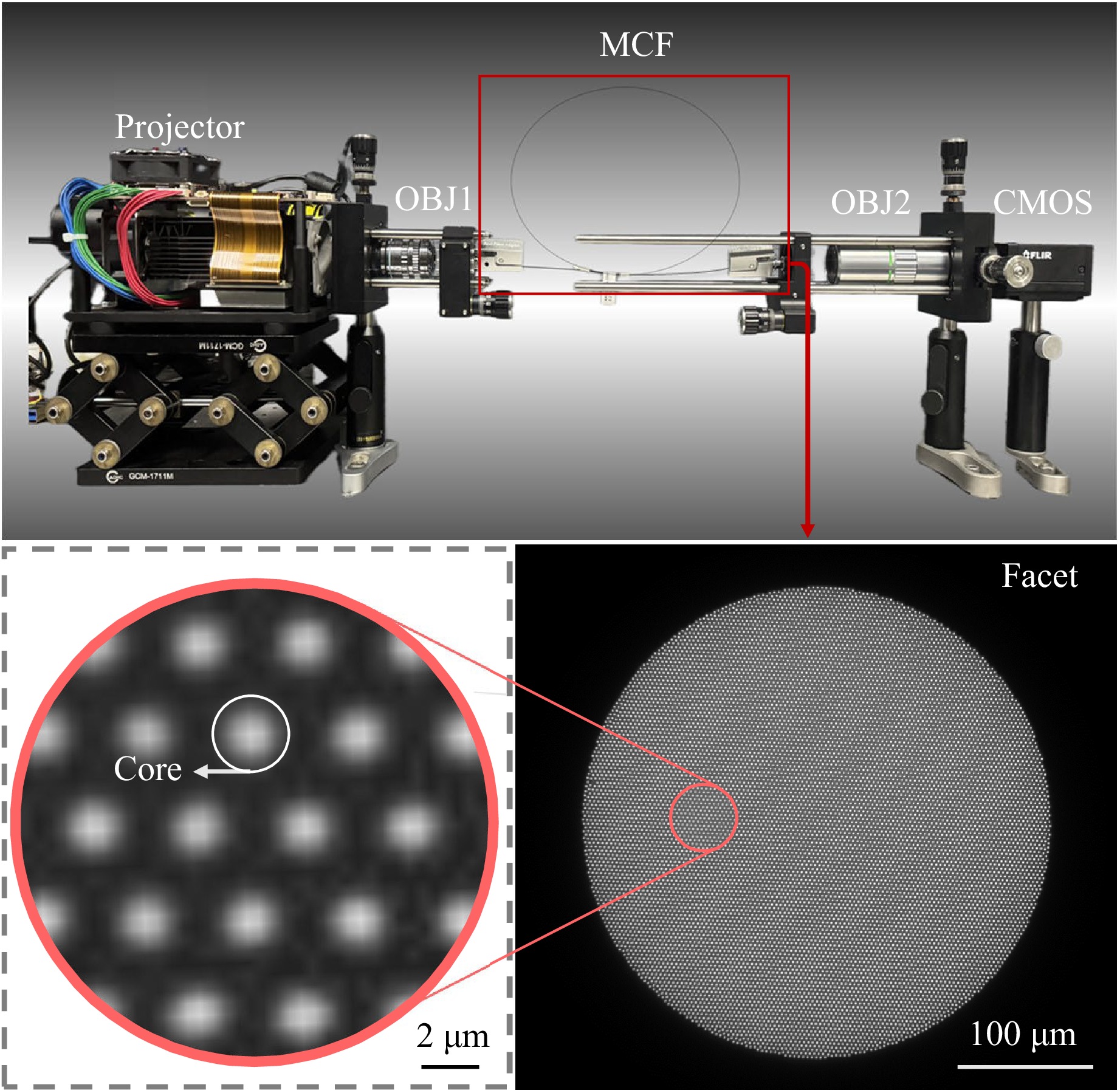
Fig. 4 Experimental setup for paired-dataset acquisition. The projector displays the GT; OBJ1 demagnifies the GT onto the distal facet of the MCF; OBJ2 (20× microscope objective) magnifies the proximal facet onto the CMOS sensor.
Compared with previous methods for obtaining paired datasets, the proposed approach requires no additional optical path for reference images, thereby reducing the system complexity and acquisition cost. Furthermore, it is more reliable than artificially synthesized datasets because it inherently reflects the physical characteristics of real image transmission through MCF.
-
We used an NVIDIA GeForce RTX 3090 GPU with 24 GB memory. With this hardware configuration, training SGARNet required approximately 21 h. For each input image, the raw measurement captured from the MCF was cropped from 4,096 × 3,000 to 368 × 368 with a negligible computational overhead, and the cropped input was then processed by SGARNet to produce an artifact-free restoration. Overall, the end-to-end pipeline reconstructed approximately 10 images per second.
-
First, we evaluated the trained end-to-end network using a validation set consisting of 200 paired images. The peak signal-to-noise ratio (PSNR) and structural similarity index (SSIM), which are two widely used metrics for image restoration and enhancement, were employed for the quantitative assessment. The proposed SGARNet effectively suppressed artifacts, resulting in significant improvements in both PSNR and SSIM, as well as noticeable enhancements in the image contrast and color balance. A summary of the quantitative results for different methods is provided in Table 1.
-
The gray-level co-occurrence matrix (GLCM) is a widely used fundamental method for extracting image texture features67. In this study, for each image, we computed GLCM with an inter-pixel distance $ d=1 $ at four orientations: $ 0 $, $ \text{π}/4 $, $ \text{π}/2 $, and $ 3\text{π}/4 $. We then defined the textural complexity as follows:
$$ {{T excomp}} = 0.5 \times \frac{1}{{{\mathop{\text {Norm}}\nolimits} ({\text{ASM) + }}\varepsilon }} + 0.5 \times {\mathop{\text {Norm}}\nolimits} ({\text{Con)}} $$ (17) where ASM denotes the angular second moment of the GLCM, reflecting the uniformity of the gray-level distribution and coarseness of the texture. A small constant $ \varepsilon $ is introduced to avoid division by zero, as in Eq. 15. Con denotes the GLCM contrast, which reflects the image sharpness and depth of the texture grooves.
A comparison of textural complexities using the PSNR and SSIM across different methods on the test dataset is shown in Fig. 5. The proposed SGARNet exhibited consistent superiority in terms of honeycomb artifact removal.
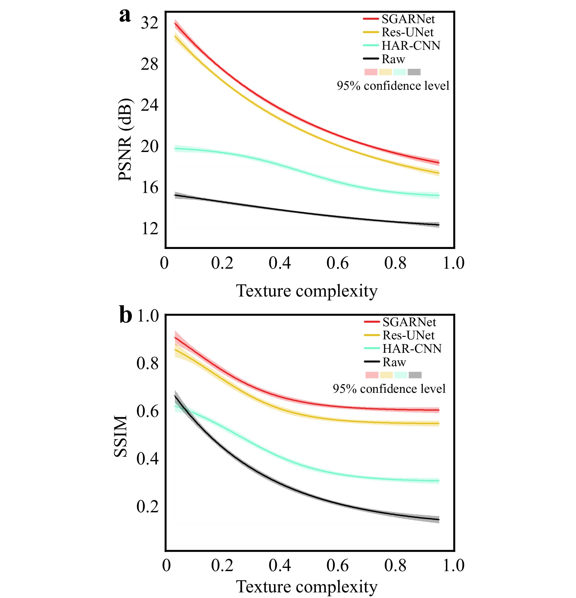
Fig. 5 PSNR and SSIM according to various textural complexities across the entire test set.
For images with Texcomp values below 0.5, where the intrinsic contrast is low and the texture distribution is relatively uniform, the proposed SGARNet demonstrates outstanding restoration capability. Specifically, the PSNR was improved from 15.14 dB to 31.66 dB, whereas the SSIM increased from 0.3894 to 0.8760. A comparison between SGARNet and other deep-learning-based methods is shown in Fig. 6a, with the quantitative metrics annotated in the bottom right of the images.
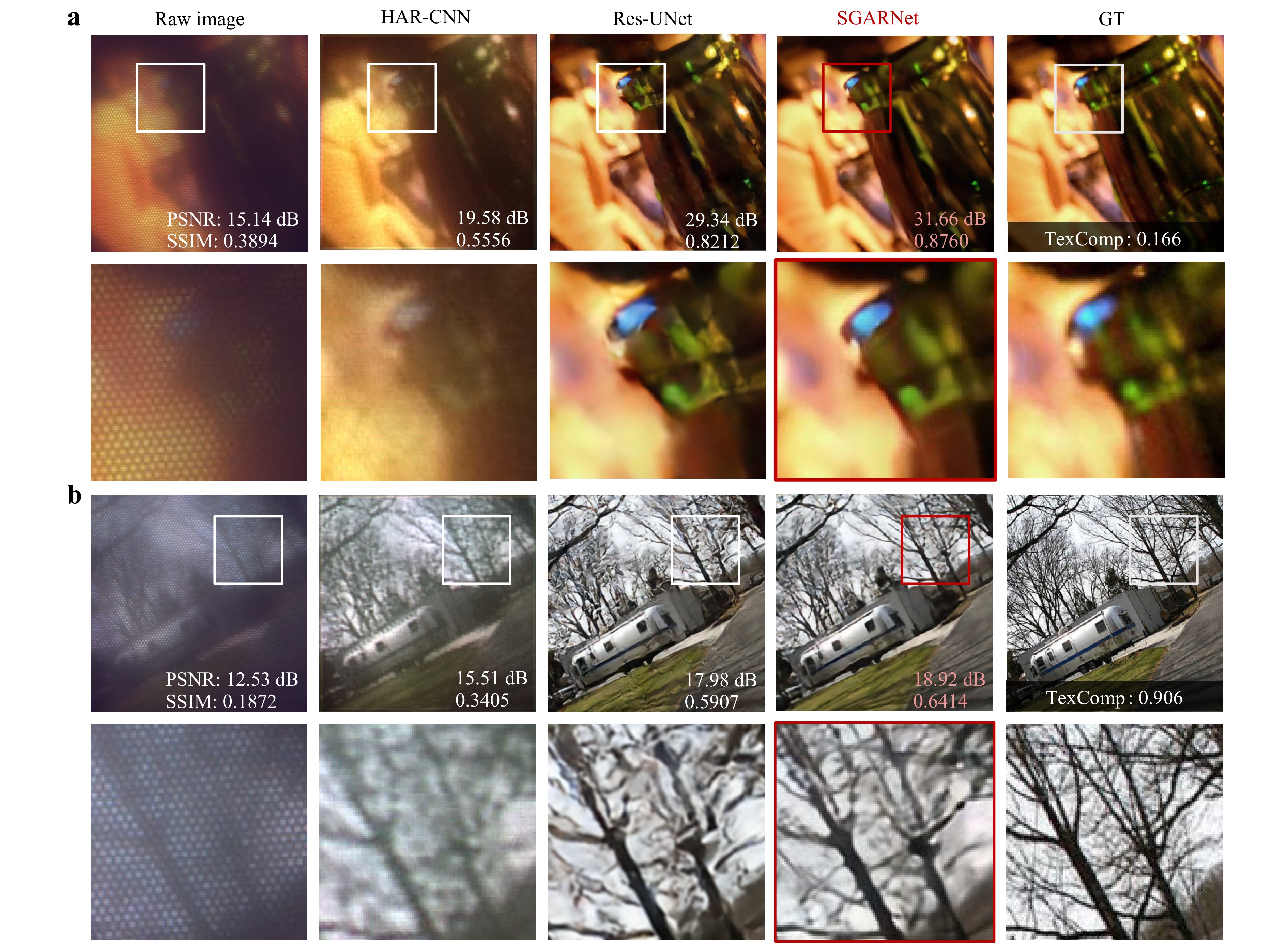
Fig. 6 Restoration results for images with Texcomp of a 0.166 and b 0.906. Top row: full 368 × 368 images; bottom row: zoomed-in crops. Columns (left to right): MCF raw images with honeycomb artifacts; HAR-CNN-restored images; Res-UNet-restored images; SGARNet-restored images; GT.
For images with Texcomp values above 0.5, as shown in Fig. 6b, richer high-frequency details are presented. As revealed by our degradation model, high-frequency information is inevitably lost during MCF transmission owing to discretized sampling. Consequently, single-frame deep-learning methods struggle to achieve faithful recovery of the missing high-frequency content.
Res-UNet is a widely used neural network for improving image quality. The version of Res-UNet that we used employs LeakyReLU pointwise activations, which lead to irregular artifacts in the reconstruction of high-frequency details. This observation is consistent with our earlier analysis that pointwise nonlinear activations are unfavorable for the smooth suppression of regular honeycomb artifacts. In contrast, the proposed SGARNet, which eliminates nonlinear activations and is trained with a joint perceptual loss, delivered significant improvements in the quantitative metrics along with smoother suppression of honeycomb artifacts with higher fidelity.
-
SGARNet was trained on a projector-based paired dataset, but realistic imaging conditions rely on reflected or transmitted illumination. To assess the generalization capability of the model in such scenarios, we replaced the projector shown in Fig. 4 with physical objects and conducted MCF imaging using broadband white-LED.
As shown in Fig. 7a-d, we first validated SGARNet using a standard USAF 1951 resolution test target, which features a pattern with transparent lines and a reflective background. The target includes 10 groups of line pairs with equal line spacing and width (from −2 to +7), each group containing six elements (horizontal and vertical line pairs).
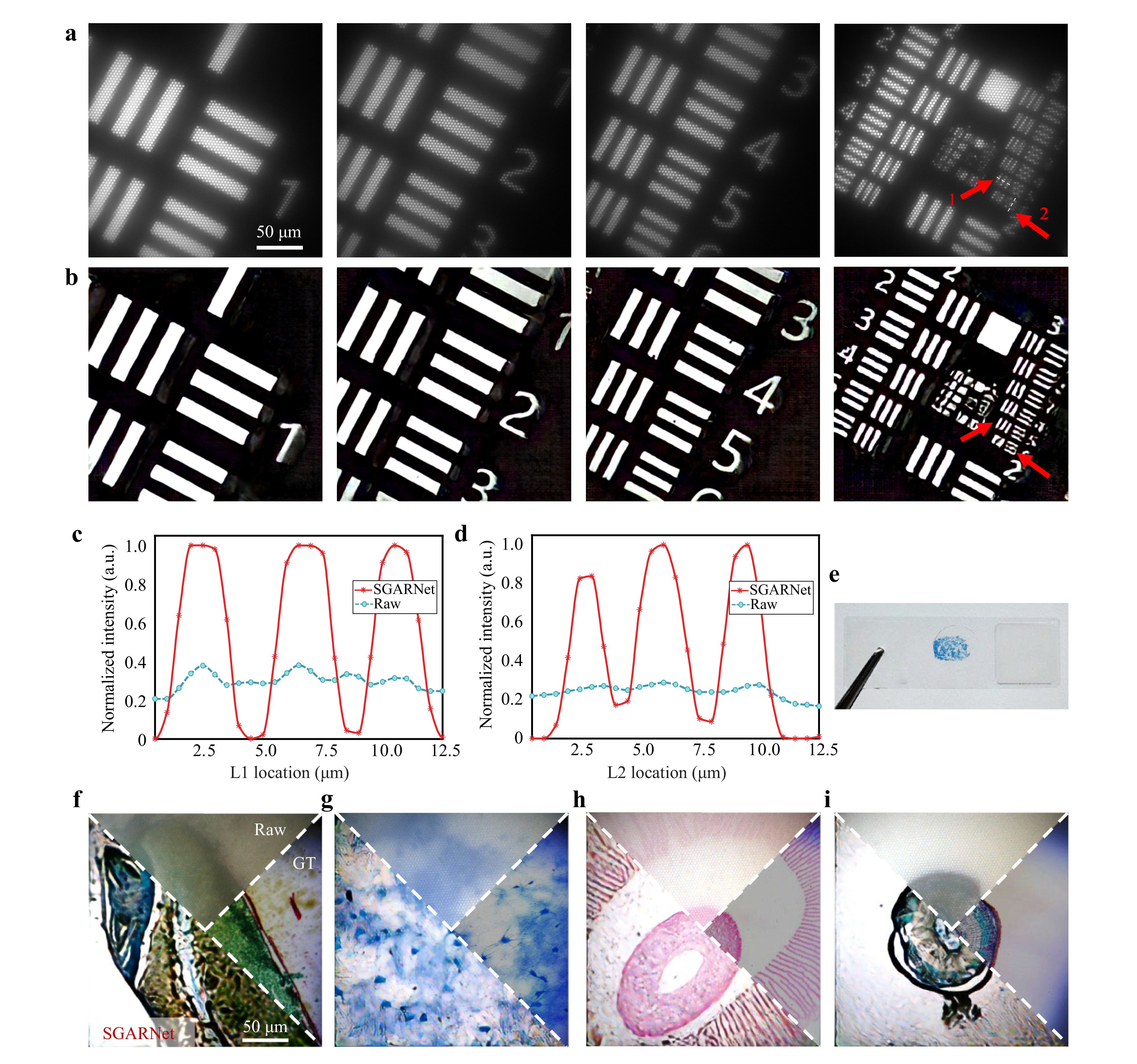
Fig. 7 Restoration results for real-object images. a Raw images of the USAF 1951 resolution test target acquired by lensless imaging at the distal facet of MCF. b SGARNet-restored images without honeycomb artifacts. c, d Intensity profiles along dashed lines L1 and L2 (marked by red arrows in a), respectively, where the horizontal axes represent the actual physical dimensions at the MCF distal facet. e Example of experimentally observed biological sample sections. f–i SGARNet-restored images of biological tissue sections. From left to right: longitudinal section of wheat caryopsis, neural tissue, agaric section, transverse section of a woody dicot stem.
Fig. 7a, b present the raw and SGARNet-restored images of elements 1 to 6 from the first to third groups of the resolution target. The MCF raw images showed pronounced hexagonal honeycomb artifacts, whereas the SGARNet restoration effectively eliminated these artifacts. The line intensity profiles extracted along the white dashed segments marked with red arrows are shown in Fig. 7c, d. These profiles demonstrate that SGARNet clearly resolved the sixth element of the third group of line pairs in the resolution target. Based on the line width of the original resolution target and magnification of the objective lens used in the experiment, the minimum line width in the projected image on the fiber facet was calculated to be 2.1 µm. This indicates that, under SGARNet enhancement, the lensless MCF imaging system can resolve a minimum line width of 2.1 µm, which is consistent with the MCF core diameter of 2 µm and inter-core spacing of 3 µm used in the experiment. These results demonstrate that SGARNet improves the image fidelity and resolution while removing honeycomb artifacts under realistic object-imaging conditions.
Furthermore, we applied SGARNet to biological tissue sections acquired under the same transmitted white-LED illumination. Fig. 7e shows an example of a neural tissue sample and Fig. 7f-i present four comparison sets of, each including the raw MCF image, SGARNet-restored image, and corresponding GT image captured by a commercial optical microscope. These results demonstrate that SGARNet remains robust for real-world color tissue imaging and can be directly transferred from projector-based training to practical biomedical imaging scenarios.
-
Lensless MCF-based endoscopy is attractive for computational imaging in biomedicine, because it enables high image quality with keyhole access, which is crucial for intra-operative monitoring. However, the periodic core arrangement of the MCF leads to sampling-induced honeycomb artifacts, that manifest as pixelation effects in the image. These artifacts degrade the image quality, making it difficult to distinguish real features. Therefore, suppressing these artifacts is essential for obtaining high-quality images. In addition to techniques such as using the MCF as a “fiber lens” that is placed away from the image plane, these artifacts can be digitally removed. However, conventional methods have a low restoration efficiency, and learning-based methods lack physics-informed priors and rely on the quality of the dataset, leading to poor robustness and generalization.
In conclusion, we have proposed SGARNet, a deep artifact removal approach for lensless MCF imaging that enables real-time, high-quality computational imaging. Compared with existing deep-learning-based methods, SGARNet offers several key innovations: (1) A degradation model was established for MCF image transmission and the unique spectral characteristics of the arranged honeycomb artifacts were analysed. (2) Guided by this model, we devised the SpectralGate module that tranforms intermediate feature maps into the frequency domain and selectively attenuates peaks at the reciprocal-lattice frequencies using a learnable frequency mask. (3) A reliable dataset containing real physical information from the imaging process was acquired for training, and the data-acquisition method did not require an additional optical path that bypasses the MCF. (4) As opposed to previous deep-learning approaches that are typically evaluated on a single type of image, our method was validated across images with varying textural complexities, real-world resolution targets, and colored biological tissue samples, ensuring robustness and significant application potential.
The results showed that SGARNet outperforms existing methods in terms of quantitative metrics and exhibits strong robustness across images with varying textural complexities. Even in challenging scenarios in which high-frequency details risk aliasing with honeycomb artifacts, SGARNet effectively suppresses these artifacts while preserving key image features. Notably, SGARNet significantly enhances the resolution and eliminates honeycomb artifacts, making it highly suitable for real-world applications that demand high image fidelity. Furthermore, the method demonstrates strong generalizability, as shown by its success with both resolution test targets and biological tissue samples. These findings highlight the potential of SGARNet for reliable, real-time and high-quality computational imaging in a variety of biomedical applications.
Despite the advantages of the proposed method, certain limitations remain to be addressed in future work. First, the current imaging setups utilize either active projection or transmissive LED illumination. Notably, the transmissive mode requires the samples to be transparent. However, clinical minimally invasive surgery typically requires a single MCF to perform simultaneous illumination and imaging in reflection mode. This requirement poses a challenge for future optical system designs that integrate illumination and imaging functions. Potential strategies to overcome the associated back-reflection noise include the use of cross-polarization schemes or double-clad fiber architectures68.
Fiber bending and deformation are critical practical factors in endoscopic scenarios. From a theoretical perspective, we anticipate that the SpectralGate mask will remain effective in suppressing lattice-related honeycomb artifacts under dynamic stress. This stability arises because the mask relies on a fixed-core arrangement at the proximal facet. Furthermore, the inherent lateral memory effect of the MCF ensures that speckle patterns remain highly correlated, even under bending or twisting. Nevertheless, bending-induced alterations to the fiber transmission characteristics36 could still affect the fidelity of fine-detail restoration, making dynamic stress testing an important avenue for future physical validation.
Beyond physical constraints, the generalization performance of the network is closely tied to the training data and architecture. For instance, the slight edge shadows in binary targets (Fig. 7b) arise because the network, which was trained primarily on continuous-tone images, misinterpreted PSF-blurred sharp transitions as grayscale structures. In color imaging, because the honeycomb pattern is wavelength independent, a single SGARNet can efficiently process all color channels using shared weights, ensuring structural consistency. To improve color fidelity, future work could explore channel-adaptive modulation and integrate deep-learning-based chromatic aberration correction69, which is particularly important for advanced applications like multi-color fluorescence endoscopy. Owing to the strong frequency-domain guidance provided by SpectralGate, SGARNet is data efficient, and its performance largely saturates beyond 1,000 training pairs. Therefore, we used 2,800 pairs mainly to increase the diversity across textures and imaging modalities, enabling robust generalization with a single model for both monochrome and color cameras.
In terms of scalability and real-time performance, the SpectralGate mask is intrinsically linked to the specific fiber core arrangement. Consequently, adapting the method to fibers with different core layouts requires mask redesign and network retraining. This process is particularly challenging for fibers with irregular lattices, in which the spectral peaks are less pronounced. At present, retraining takes approximately 21 h, and the inference speed is approximately 10 fps. To bridge this gap for real-time applications, which require speeds exceeding 30 fps and to enable rapid adaptation to new fibers, future work will explore strategies such as multi-GPU parallel training and transfer learning57. Addressing these aspects will enhance the capability of the system for practical applications in minimally invasive endoscopy.
-
This work was supported by the National Natural Science Foundation of China (Grant Nos. W2511066, 62235009 and 62305183), and partially funded by the Deutsche Forschungsgemeinschaft (DFG, Cz 55/61-1).

 DownLoad: