


-
In the natural world, insects, such as dragonflies, locusts, and bees, exhibit exceptional visual capabilities because of their unique compound eyes. Unlike human vision, these biological systems are composed of numerous ommatidia, each functioning as an individual photoreceptive unit, collectively offering a wide field-of-view (FoV), high temporal resolution, and excellent motion sensitivity1–3, as shown in Fig. 1a. These features enable insects to perceive and respond swiftly to dynamic changes in their surroundings, enabling effective navigation, predator avoidance, and prey capture. Such capabilities are enabled by cooperation between the compound-eye optical structure and the downstream neural processing, which together support wide-angle visual acquisition and sensitive motion perception. Inspired by these biological examples, researchers have sought to mimic the compound-eye architectures in developing advanced imaging systems4–10. However, traditional bioinspired compound eyes typically require a curved arrangement of the lens array to increase the detection FoV, which introduces considerable fabrication challenges and large device volumes.
Recent advances in metalenses have enabled the development of feasible pathways for planar bioinspired compound eyes with highly compact footprints. Metalenses are ultrathin imaging components composed of subwavelength nanostructures arranged to provide a specific focusing phase profile11–15. By implementing wavefront modulation within a single planar layer, they offer clear advantages in terms of compactness and lightweight design while maintaining high-efficiency and high-quality imaging with sub-micron structural thickness16–19. Compared with conventional miniaturised refractive imaging systems, which typically require multiple optical elements to balance the FOV and image quality, metalenses provide a flatter and lighter architecture that is well-suited for highly integrated array-based imaging platforms. Recently, metalenses have been assembled into arrays to realise complex imaging functionalities in highly integrated systems. Notable implementations include meta-microscopy that surpasses the space-bandwidth product limit20,21, light-field cameras with extreme extended depth-of-field22, achromatic metalens array-based light-field cameras23, and spectroscopic light-field cameras24. However, most of these metalens-array-based imaging devices fail to replicate the ultrawide-FoV characteristics of the compound eyes of insects. Moreover, these devices are predominantly designed for static scenes or stationary objects and exhibit limited capabilities for detecting dynamic or moving targets.
This study introduces a planar intelligent nanophotonic sensor (PINS) based on a metalens array capable of ultrawide-angle and precise motion perception. Although metalenses are arranged on a flat substrate, their carefully engineered phase profiles enable each individual metalens to be imaged from a distinct angular direction25, thereby emulating the wide-FoV functionality of insect compound eyes. This design enables the PINS to achieve horizontal imaging coverage exceeding 135°. This study further integrated a deep neural network, called meta-motion sense (MMS), to accurately extract optical flow from sequential wide-FoV images captured by the PINS, in a manner analogous to downstream neural processing that transforms visual inputs from insect compound eyes into motion-related information. This allows for a comprehensive characterisation of the motion dynamics in a scene, including the velocity and direction of multiple moving targets26–32. To efficiently train the MMS neural network to process the specialised metalens imaging data, a convolution imaging model was developed using point spread functions (PSFs). This imaging model enables the rapid and high-quality generation of large-scale training datasets. Benefiting from this targeted training strategy, the PINS achieved high-accuracy motion detection even under challenging conditions, including ultra-small or ultra-slow-moving objects and dynamic targets embedded in complex backgrounds, scenarios where conventional machine vision systems often fail. By thoroughly analysing the extracted optical flow information, the proposed method enables intelligent and accurate prediction of future trajectories of moving objects. This predictive capability holds significant potential for future applications in autonomous driving, motion risk assessment, and other dynamic scene-understanding tasks. Furthermore, the proposed PINS is lightweight and readily deployable on mobile platforms such as miniature unmanned aerial vehicles (MAVs), wearable electronics, and other portable devices, thereby significantly increasing its adaptability and expanding its applicability across diverse scenarios.
-
PINS is a highly compact self-assembled imaging device. This study integrated a PINS into a miniature unmanned aerial vehicle (MAV), as shown in Fig. 1b, enabling it to perform agile and flexible environmental sensing akin to insect behaviour. Details of the integration are provided in Supplementary Note S1. The architecture of the PINS is illustrated in Fig. 1c. Its core component was a wide-angle metalens array that mimicked the compound eyes of insects, facilitating image acquisition over a broad FoV. The underlying operating principle is elaborated later in this section. The images captured by the metalens array were projected onto a CMOS sensor (OV2640) interfaced with a microcontroller unit (MCU, ESP32-CAM) via a high-speed data interface that functionally mimicked the insect retina and nervous system. The OV2640 provided a maximum native resolution of 1,600 × 1,200 at 15 fps, whereas the final reconstructed wide-angle image in the present configuration had an effective resolution of approximately 480 × 1,440. This choice reflects a tradeoff between spatial and temporal precision, balancing image detail preservation with a sufficient frame rate for reliable motion analysis.
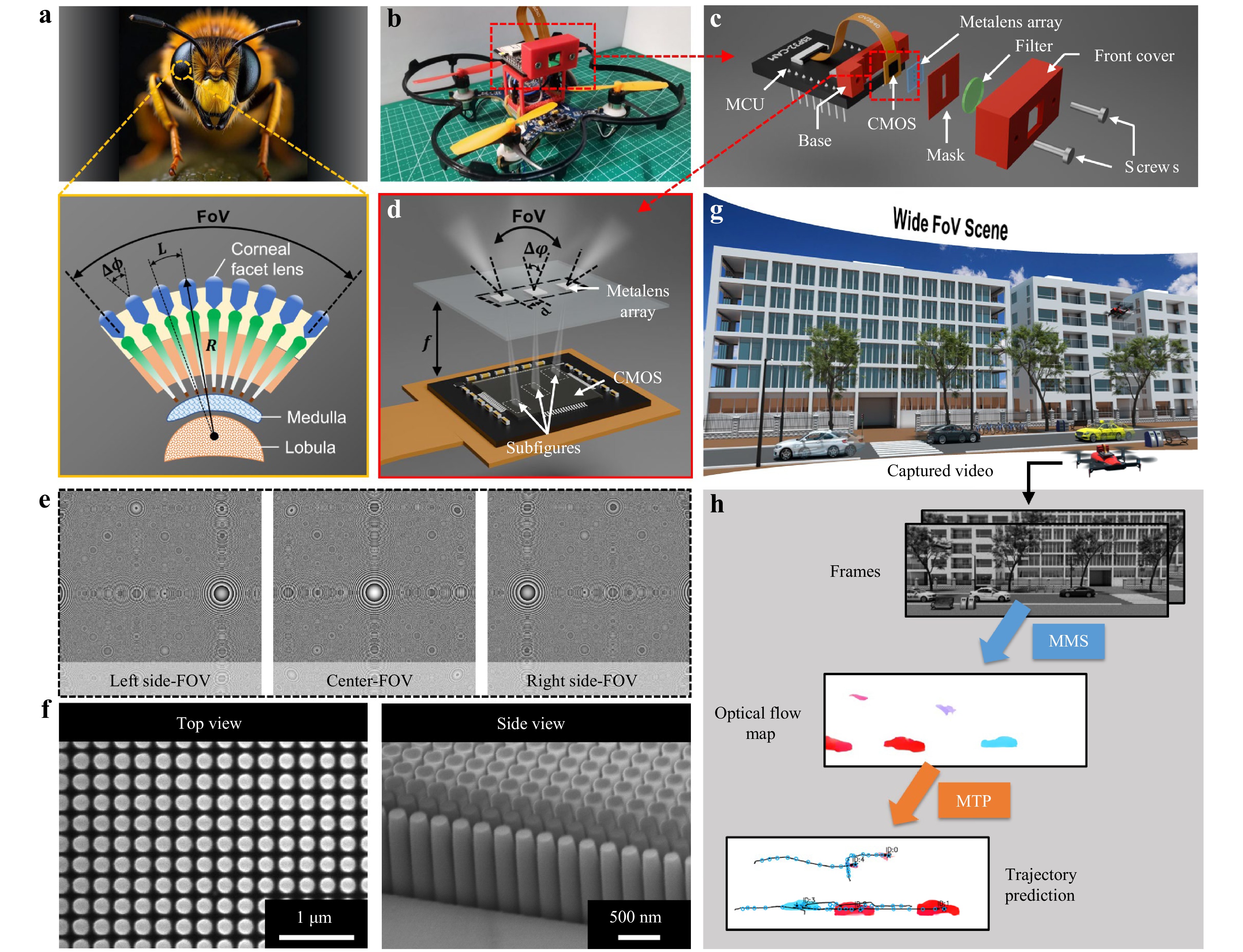
Fig. 1 Architecture and working principle of the proposed planar intelligent nanophotonic sensor (PINS). a Conceptual illustration of a bee and its compound eye structure consisting of numerous ommatidia arranged on a curved surface to achieve a wide field-of-view (FoV). b Illustration of a miniature unmanned aerial vehicle (MAV) equipped with PINS, inspired by the compound-eye structure. c Schematic of PINS architecture. The core system integrates a metalens array, 550 nm optical filter, stray light-blocking mask, CMOS image sensor, and microcontroller unit, all enclosed within a compact 3D-printed modular housing. d Illustration of the imaging process using a wide-angle metalens array. e Phase profiles of the three metalenses in the metalens array. f Top and side views of the scanning electron microscopy (SEM) images of the fabricated nanostructures. g Schematic of wide-angle detection using the PINS-integrated MAV. h Process of motion detection and trajectory prediction using PINS.
To improve the imaging quality, a stray light-blocking mask and a bandpass optical filter centred at 550 nm were integrated into the PINS to suppress ambient broadband illumination and out-of-band environmental interference, thereby enhancing the image contrast and signal-to-noise ratio under practical operating conditions. The mechanical components, including the base mount and front cover, were fabricated by 3D printing using polylactic acid (PLA). The CMOS sensor was fixed at the centre of the base mount using an instant adhesive, and the mount was attached to the top front side of the MCU using the same adhesive. The optical components, including the metalens array, optical filter, and stray light mask, were bonded using an optically clear adhesive (OCA, Tesa 69042), and the entire assembly was embedded into the inner surface of the front cover. To precisely adjust the spacing between the metalens array and the CMOS sensor for optimal imaging performance, two M2 screws were used to fasten the front cover to the base mount. The sensor–metalens distance can be finely tuned by varying the insertion depth of the two screws. This adjustability is particularly critical for metalens arrays to adapt to the imaging length of targets at varying distances, thereby significantly enhancing the practical applicability of the integrated sensor.
The key component, a wide-angle metalens array, comprises three carefully phase-engineered metalenses, each with a diameter of 1 mm and focal length of 1.6 mm. Each metalens captured a distinct 45° viewing angle range and collectively enabled imaging across a total horizontal FoV exceeding 135°, as illustrated in Fig. 1d. The phase profile of the metalens responsible for the central FoV was optimised using a ray-tracing method (see Methods and Supplementary Note S2 for details). In contrast, the phases of the metalenses for the two side FoV were derived by superimposing an additional tilt phase ±kdsin45° to the central-FoV metalens phase profile, where k is the wave number and d is diameter of the metalens. The phase profiles of the three metalenses are shown in Fig. 1e, clearly revealing a tilted phase. To achieve high-efficiency light modulation, the metalens array employed Si3N4 subwavelength scale cylindrical nanostructures with a height of 1 μm, which manipulated the wavefront based on propagation phase principles33–36. The detailed relationship between the modulation phase and the nanostructure parameters, along with the fabrication process, is provided in the Methods section. The top and side views of the scanning electron microscopy (SEM) images of the fabricated nanostructures are shown in Fig. 1f, demonstrating structural uniformity and fabrication precision. As shown in Fig. 1g, the fully assembled PINS system could capture wide-angle scenes and sequentially record each frame, encompassing both the static environment and the dynamic moving objects. Based on the extracted optical flow, the motion states of the objects and their predicted trajectories were subsequently derived using a motion trajectory prediction (MTP) framework, as illustrated in Fig. 1h.
-
To enable the PINS to efficiently extract optical flow information from wide-angle scenes, a large and representative dataset is required to thoroughly train the MMS neural network. Each training sample must consist of a pair of consecutive image frames acquired by the metalens-based system along with the corresponding ground-truth optical flow maps. However, no existing public dataset satisfies these requirements, necessitating the creation of a custom dataset. A straightforward approach involves adapting established optical flow datasets, such as FlyingChairs37, Sintel38, KITTI39, and HD1K40 by replacing the original scenes with images captured using the PINS system. The experimental setup for the data acquisition is shown in Fig. 2a. Specifically, images from the FlyingChairs dataset were displayed on a high-definition (HD) screen, and the PINS was positioned in front of the screen to capture the projected dataset. The captured image sequences were wirelessly transmitted to a computer for storage and processing.
First, the proposed setup was used to validate the wide-angle imaging capability of the PINS. A wide-field letters pattern (“SEU Radio & PML”) was projected onto the HD screen and imaged by both PINS and a conventional hyperbolic phase metalens. For PINS, the subimages captured by the three metalenses were individually corrected for distortion and stitched into a composite image, achieving a combined FoV of 135°, as shown in the first row of Fig. 2b. The detailed wide-angle image reconstruction pipeline is described in Supplementary Note S3. This distortion correction and stitching pipeline is computationally efficient, with an average processing time of 32.19 ms per frame. In contrast, the image of the hyperbolic phase metalens covered less than one-third of the FoV, as illustrated in the second row of Fig. 2b.
However, constructing an optical-flow training dataset directly from metalens-captured images poses several challenges. First, collecting a large volume of real-world image sequences and manually annotating the corresponding optical flow are both time-consuming and labour-intensive. Second, the inherent distortions introduced by the metalens system, although partially mitigated through calibration, cannot be entirely eliminated. Residual discrepancies between captured images and their ideal references hinder the generation of accurate ground-truth optical flows. To address these issues, an imaging model that convolved the original images with an experimentally measured PSF was adopted to generate extensive training datasets. The PSF effectively characterized the imaging response of the PINS, capturing critical aspects such as imaging intensity, imaging quality degradation, and imaging distortion41. The imaging model can be expressed as
$$ I_{\text {max }}=\Gamma(O \otimes \operatorname{PSF}+N) $$ (1) where O denotes the original input image, $ \otimes $ denotes the convolution operator, N denotes the sensor noise, and Γ(∙) denotes the gamma correction function used to simulate brightness attenuation. Additional details of the sensor noise model and gamma transformation are provided in Supplementary Note S4 and Note S5, respectively. The experimental setup used to obtain the PSF was the same as that employed for the direct imaging detection, as shown in Fig. 2c. A point with a diameter spanning 10 pixels was projected onto the HD screen and imaged using the PINS, which served as the PSF of the imaging model. Because of the narrow bandpass filter in the optical path, the captured images were effectively monochromatic, making the wavelength-dependent PSF variations negligible. Similarly, because all experimental scenarios were located within the depth of field of the system, the distance-dependent PSF variations could also be neglected under the present operating conditions. A detailed depth-of-field analysis of the PINS system is provided in Supplementary Note S6.
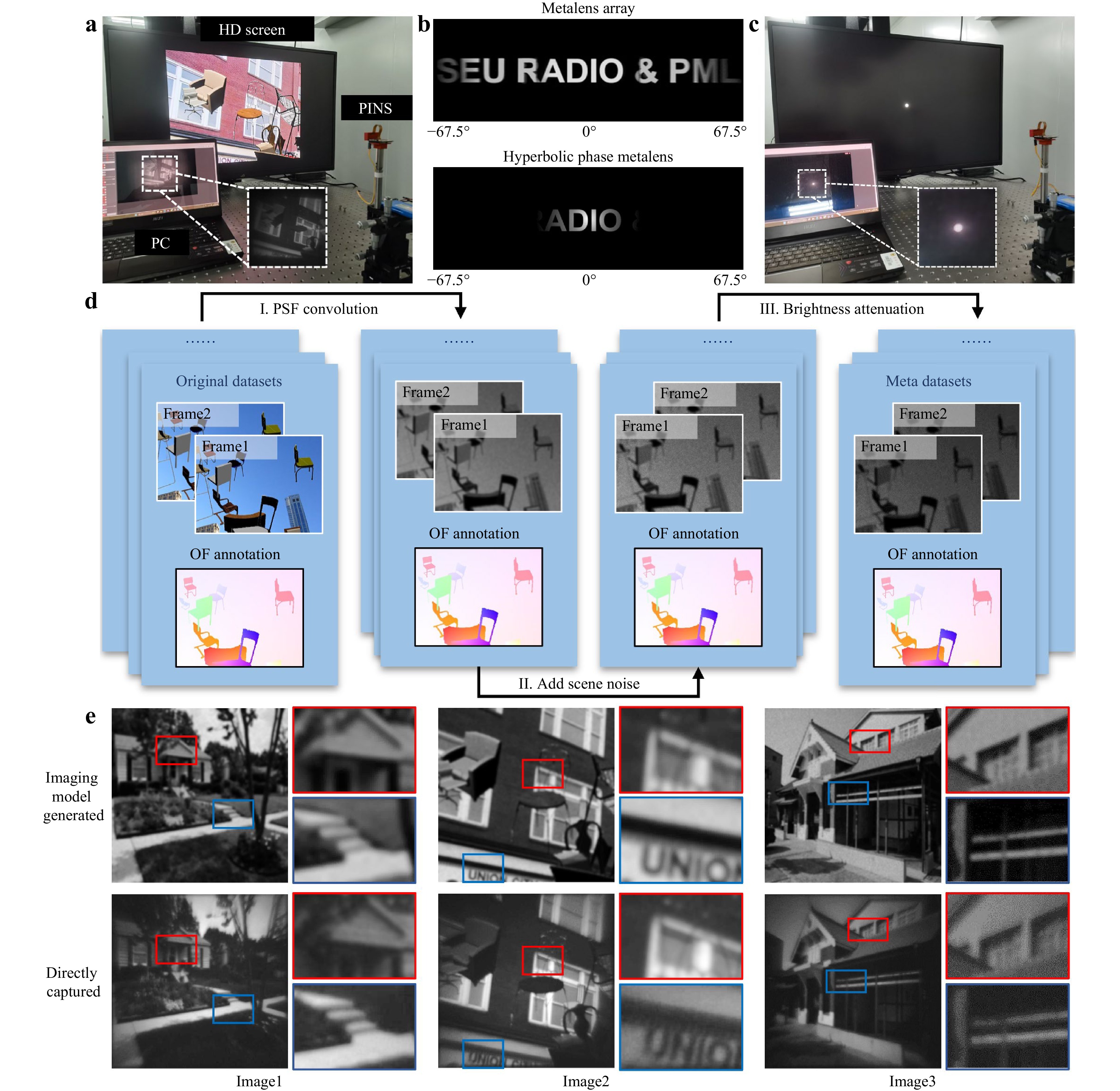
Fig. 2 Generation of extensive high-quality training data. a Experimental setup for direct image acquisition using PINS, with Wi-Fi transmission to a PC for visualization and storage. b Comparison of the imaging results from the wide-angle metalens array (first row) and a conventional hyperbolic phase metalens (second row). c Experimental setup for acquiring the point spread function (PSF). d Flowchart illustrating the construction process of the Meta dataset. e Detailed comparison between images generated by imaging model (first row) and those directly captured by the PINS (second row). Highlight enlarged regions for detail comparison. Abbreviations: HD: high-definition; PC: personal computer; OF: optical flow; and PSF: point spread function.
Based on the collected PSF and the imaging model described in Eq. 1, a large amount of simulated metalens imaging data that closely approximated the real experimental captures was efficiently generated. The overall workflow for constructing this specialised optical-flow dataset for the PINS is illustrated in Fig. 2d. The original dataset consisted of paired scene images and their corresponding optical flow ground truths. During the dataset synthesis, the optical flow ground truths were retained, whereas the paired scene images were sequentially processed using the imaging model, which included PSF convolution, noise addition, and gamma-based brightness attenuation. Because the imaging model preserves the spatial consistency of the object positions, the original optical flow labels remain valid and can be reused directly without additional annotation. The resulting dataset not only satisfied the scale requirements for deep network training but also captured the distinct statistical features inherent to metalens imaging. This physics-consistent simulation process further helps to mitigate the risk of hallucinated features during network training.
To assess the fidelity of the imaging-model-generated dataset, three representative scenes captured directly by the PINS were compared with their imaging-model-generated counterparts, as shown in Fig. 2e. The simulated results exhibited strong visual agreement with the experimental images in terms of brightness, blur level, and overall appearance. Two representative regions from each image were selected and magnified for further inspection. The simulated images showed excellent consistency with the real captures, with no noticeable differences in the texture edges or contrast levels. Quantitative similarity metrics for the corresponding image pairs in Fig. 2e and a comparison between the experimentally captured and PSF-model-simulated wide-FoV images are provided in Supplementary Note S7.
-
By leveraging the datasets obtained from the PSF-convolution imaging model, a neural network for motion detection is proposed, referred to as MMS. As shown in Fig. 3a, the architecture of the MMS computes the interframe correlations to guide the iterative refinement of a zero-initialised optical flow, progressively updating it to yield a final accurate optical flow estimation. Before the iterative refinement begins, a four-dimensional (4D) correlation volume pyramid was precomputed to encode the motion cues across multiple spatial scales. This pyramid was constructed by first extracting feature maps F1 and F2 from two consecutive input frames I1 and I2 using a dual-stage multi-scale composite encoder (DSMSCE). The correlation volume C was then calculated by performing dot-product similarity between all the spatial locations in the two feature maps. To enable multiscale motion estimation, average pooling operations with kernel sizes of one, two, four, and eight were applied to the last two dimensions of C, forming a 4D correlation volume pyramid denoted as {C1,C2,C3,C4}. Each pyramid level captures displacement information at a different spatial scale, enabling the network to robustly match features across a wide range of motion magnitudes. However, it is important to note that although the network possesses strong feature extraction capabilities, optical phase optimisation to reduce image distortion remains crucial. This is a prerequisite for network performance because the quality of the input image influences the network's ability to extract meaningful features and make accurate predictions. An additional analysis of the effects of imaging noise and distortion on optical flow estimation is provided in Supplementary Note S8.
Next, the optical flow was initialised from the starting point f0 = 0, and then iteratively refined through a recurrent update mechanism. At each iteration, the current estimated flow $ {\boldsymbol f}_{k} $ was used to sample the multiscale correlation features from the pre-computed correlation volume pyramid. These features, together with the current flow and latent hidden state, were passed to an update operator based on a convolutional-gated recurrent unit (ConvGRU). The module outputted a flow increment $ \Delta \boldsymbol{f} $ and an updated hidden state, which were used to refine the flow estimate. This iterative refinement process enabled the network to progressively improve the accuracy of the optical flow estimation. Once the final low-resolution optical flow was obtained, a learnable convex upsampler was used to restore it to the full input resolution. See Supplementary Note S9 for further architectural details of the MMS.
Detailed architecture of the DSMSCE is illustrated in Fig. 3b. The dual-stage multiscale parallel encoding and feature fusion design enabled the network to capture fine-grained details from shallow layers while simultaneously aggregating global contextual information from deeper layers. This architecture integrated three key components: a shallow spatial pyramid pooling (SSPP) block, a basic encoder block, and a deep atrous spatial pyramid pooling (DASPP) module. First, the SSPP module operated on shallow features and captured spatial statistics at the global, mid-level, and local scales in parallel. Second, the basic encoder block comprising six sequential residual blocks was organised into three hierarchical stages. The first stage (Layer 1) maintained 64 channels and preserved the spatial resolution with a stride of 1, focusing on the fine-grained enhancement of the input features. In the second stage (Layer 2), the number of channels was increased from 64 to 96 through the first residual block, which was accompanied by spatial downsampling with a stride of two. A residual block with 96 channels was used to further refine the extracted features. The third stage (Layer 3) adopted a similar structure, increasing the channel depth to 128, which facilitated a deeper feature representation and a larger receptive field. Third, a DASPP module was introduced to further enhance the capacity of the encoder to capture large displacements and complex structures. This module extracted features with varying receptive fields in parallel from deep feature maps, while also incorporating global context information. Consequently, it significantly improved the joint modelling of local structural details and global semantic context. Additional design details of the DSMSCE module are provided in Supplementary Note S10.

Fig. 3 Architecture of a meta-motion sense (MMS) neural network. a Overall framework of MMS. The process indicated by the dashed lines is executed only in the initial iteration. b Detailed architecture of a dual-stage multi-scale composite encoder (DSMSCE).
A dataset comprising approximately 25,200 image pairs was constructed using a PSF-convolution-based imaging model. Among these, 24,000 pairs were allocated for training, while the remaining 1,200 pairs were reserved for validation and testing. The optical-flow estimation was supervised using a full-sequence L1 loss function (see Supplementary Note S11 for details). The model was implemented using PyTorch and trained on an NVIDIA RTX 4090 GPU for approximately 60 h. Furthermore, the runtime of the motion detection was evaluated using GPU-synchronised timing. On the same GPU, the network achieved an average inference time of 110.15 ms per image pair, corresponding to approximately nine image pairs per second.
-
Following extensive training, the MMS neural network empowered the PINS with high-precision motion perception in ultrawide FoV scenes. To evaluate the sensing performance systematically, a series of wide-field scenes containing diverse moving targets was constructed, and then, they were captured using the setup shown in Fig. 2a. Subsequently, two approaches were adopted for dynamic object detection comparison: an established machine-vision-based object recognition algorithm (YOLO neural network42–44) and the proposed MMS-based motion perception framework. Although YOLO was primarily designed for static object classification, it was augmented with localisation capabilities, enabling it to identify the spatial coordinates of the detected targets. By comparing these positions across successive frames, the motion vectors of the targets could be inferred. Fig. 4a-c illustrate the target detection results obtained using the enhanced YOLO network.
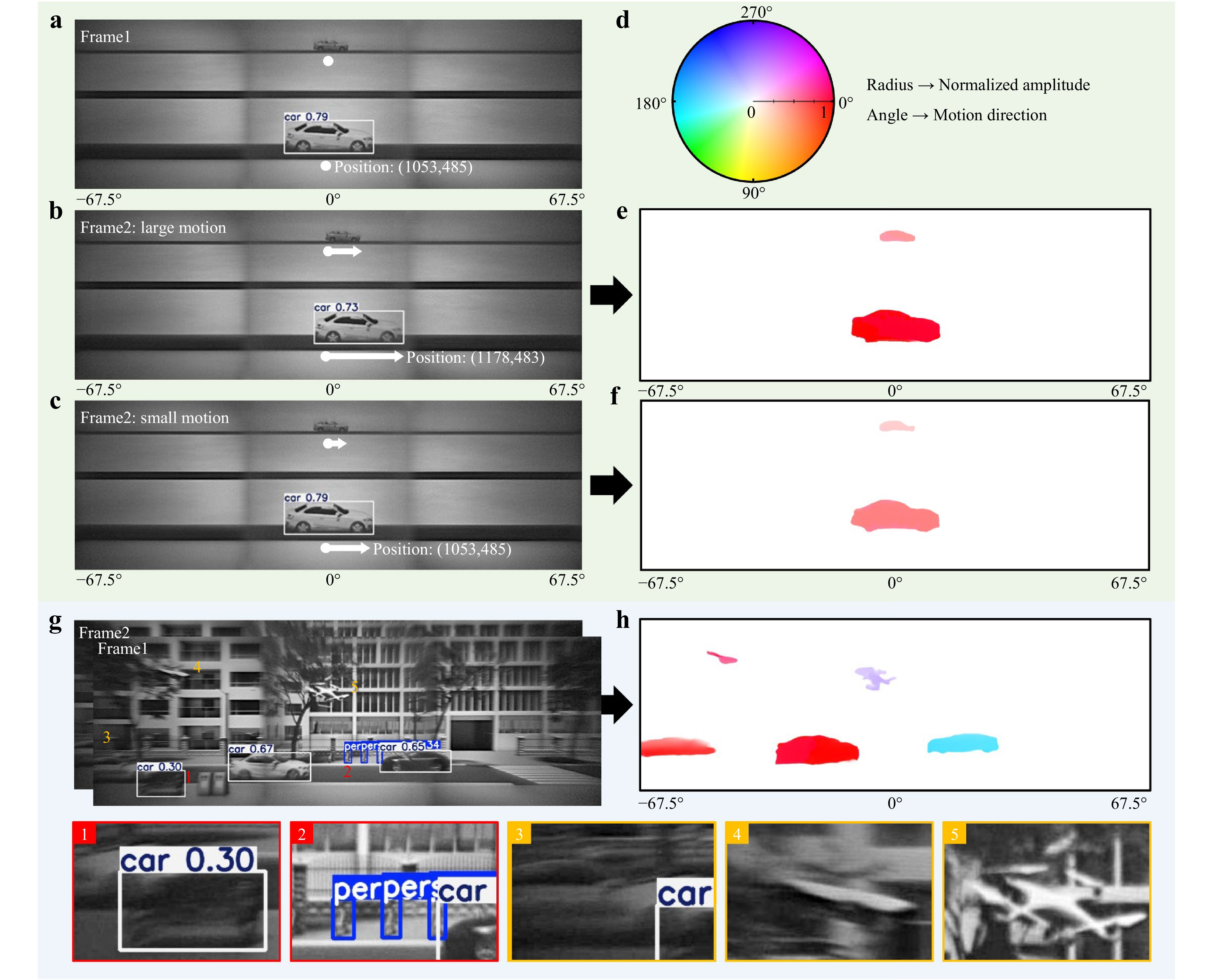
Fig. 4 Comparisons of motion detection performances between a conventional computer vision approach and the proposed meta-motion sense (MMS) neural network. a Detection results of two cars with different sizes using computer vision method, in which the large-sized car is successfully identified, while the small-sized car failed to be identified. b Detection results of the cars with a significant forward displacement using the computer vision method, in which the motion of the large-sized car can be detected. c Detection results for vehicles with small forward displacements, showing that the computer vision method fails to reliably detect subtle motion. d Colour wheel used for optical flow visualization. The angle represents flow direction (encoded by hue), and the radius represents normalized flow magnitude (encoded by saturation). e, f Optical flow results obtained by applying the MMS neural network to images in b, c, respectively, using Fig. 4a as the reference frame. g Multi-object detection results in a wide-angle scene with a complex background using the computer vision method, showing misidentifications (highlighted in red) and missed detections (highlighted in yellow). h Optical flow results for the same wide-angle scene with a complex background, in which all moving objects are effectively detected, demonstrating the robustness of the MMS neural network in motion detection.
Fig. 4a presents the detection results for two moving targets of different sizes in a wide-angle scene with a simple background. The large vehicle category and position were accurately identified using the YOLO algorithm, whereas the small vehicle failed to be recognised owing to imaging blur and noise limitations. Fig. 4b shows the detection results of the second frame using the YOLO network, where both large and small vehicles underwent obvious displacements. Although larger vehicles continued to be reliably detected and localised, smaller vehicles were still missed. The motion of a large vehicle could be inferred from the change in position across the frames. However, when a large vehicle experienced a small displacement, as shown in Fig. 4c, the YOLO network failed to capture the subtle motion, with the detected position remaining unchanged from that in Fig. 4a. These results indicate that the established YOLO algorithm struggled to detect small-sized or slow-moving objects.
In contrast, the proposed MMS neural network, after comprehensive training, enabled reliable identification of targets even under challenging conditions, such as low visibility, small object scale, or minimal movement. Fig. 4e displays the optical flow output generated by feeding two frames, as shown in Fig. 4a, b in the MMS neural network. Notably, both large and small moving vehicles were successfully detected. The motion characteristics of each target could be interpreted by referencing the optical flow colour encoding, as indicated by the coloured wheel in Fig. 4d. Each hue (angular position) corresponds to a specific motion direction, whereas saturation (radial position) represents the motion magnitude, enabling an intuitive visualisation of both the direction and speed of the object movement. Fig. 4f presents the optical flow results for the subtle motion scenario depicted in Fig. 4c. Despite the minimal displacement, the proposed method accurately captured the movement of both small-sized and slow-moving targets when the YOLO method failed.
Furthermore, a comparative evaluation of the traditional YOLO algorithm and the proposed MMS neural network was performed in a wide-angle scene featuring multiple moving objects and a complex background, with the aim of comprehensively assessing the motion detection performance. As shown in Fig. 4g, the presence of intricate background textures significantly degraded the performance of YOLO-based object detection, which relied heavily on the boundary shape features for classification. Several representative recognition errors including misidentifications and missed detections are shown in the figure. Misidentified targets are labelled with red indices (1 and 2) and are further illustrated in enlarged views at the bottom, highlighted by red dashed boxes. Missed detections are marked with yellow indices (3, 4, and 5) and are shown in the corresponding magnified regions outlined in the yellow dashed boxes. In contrast, the proposed MMS-based approach robustly and accurately captured the motion of all moving objects, even in visually cluttered environments, as illustrated in Fig. 4h. Overall, the proposed optical flow estimation method demonstrated highly accurate and robust motion detection capabilities, particularly in scenarios involving small-scale, slow-moving objects and complex background conditions, effectively compensating for the shortcomings of conventional intelligent object recognition algorithms and providing a more stable motion detection performance. To further probe the motion detection limits of the PINS, test scenarios involving extremely small displacements and miniature moving targets were designed, and the resulting optical flow outputs were systematically analysed. Details are provided in Supplementary Note S12.
-
Motion trajectory prediction plays a crucial role in enabling intelligent systems to understand and anticipate future movements of dynamic objects. By forecasting how targets move over time, proactive decision-making can be enabled in a variety of applications such as collision avoidance in autonomous driving, motion planning in robotics, and situational awareness in surveillance. Accurate trajectory prediction enhances system responsiveness, safety, and efficiency, particularly in complex and rapidly changing environments. An MTP framework that leverages optical flow information was developed to forecast future positions of moving objects. Given a sequence of optical flow maps as the input, the MTP framework produces a predicted object trajectory over a future horizon.
Fig. 5a illustrates the MTP framework for estimating the future state of a single object from a sequence of optical flow maps, where N denotes the current frame. Specifically, the framework integrates four key components: region of interest (ROI) extraction, current centroid position estimation, velocity preprocessing and fitting, and future position estimation using trajectory extrapolation, thereby enabling robust and accurate motion forecasting. First, ROI extraction was performed by identifying the dominant moving region in the optical flow map using magnitude thresholding and connected-component analysis. Second, the centroid of the extracted region was estimated as the position of the current object. Third, the velocity within the ROI was computed in terms of magnitude and direction, followed by Kalman filtering to suppress noise45, and then modelled over a recent temporal window using weighted polynomial regression. Finally, the fitted velocity model was extrapolated from frame N+1 to N+K, and the predicted trajectory was obtained by integrating the extrapolated velocity vectors, yielding the forecasted object position (Output I of Fig. 5a) and motion path (Output II in Fig. 5a). The detailed processing procedure and mathematical formulations are provided in Supplementary Note S13. Supplementary Note S14 presents an analysis of the impact of the polynomial fitting order and length L of the recent window on trajectory prediction performance. Because of its lightweight computational architecture, the proposed MTP framework enables rapid motion prediction with an average prediction time of 3.21 ms per frame for a single target.
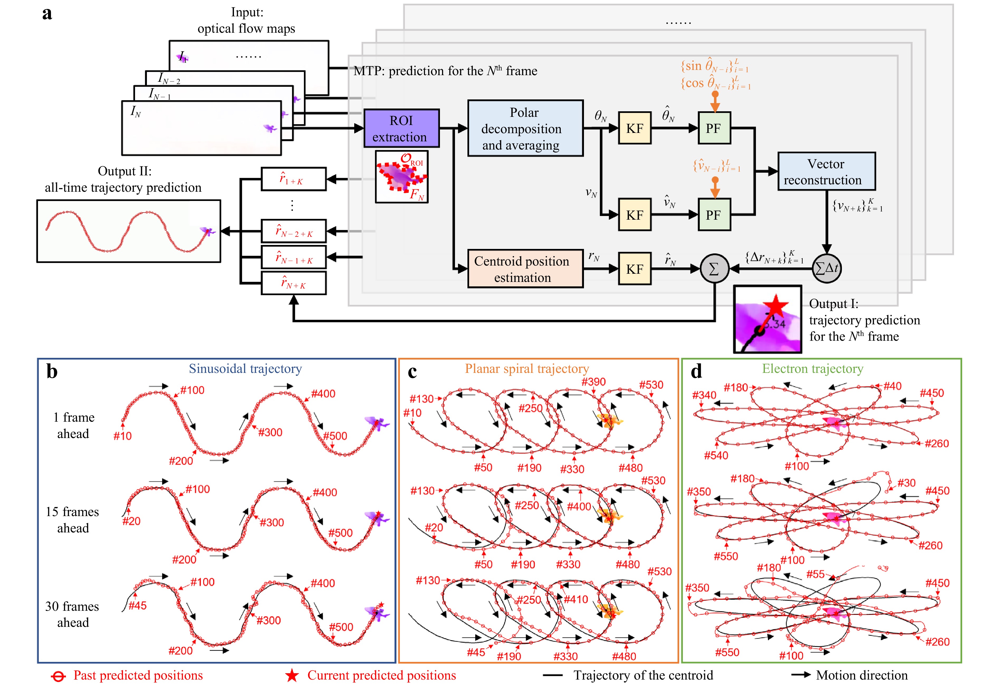
Fig. 5 Single-object trajectory prediction using the motion trajectory prediction (MTP) framework. a Processing flowchart of single-object trajectory prediction using the MTP framework. b-d Predicted trajectories for different motion patterns: sinusoidal, planar spiral, and electron trajectory. Red circles indicate predicted positions at previous frames. The five-pointed star denotes the predicted position inferred from the current frame. The frame numbers corresponding to selected representative predicted positions are labelled nearby. Abbreviations: KF: Kalman filtering; and PF: polynomial fitting.
To evaluate the trajectory prediction performance of the MTP framework, the results for three representative motion patterns, sinusoidal, planar spiral, and electron trajectories, are shown in Fig. 5b-d. For each case, predictions are shown at 1, 15, and 30 frames into the future, corresponding to time horizons of 0.03, 0.5, and 1 s, respectively (at a frame rate of 30 fps). The red circles indicate the predicted positions in the previous frames. The five-point star denotes the position predicted from the current frame. The solid black line represents the centroid trajectory. When the prediction horizon was as short as one frame, the predicted trajectory remained highly consistent with the practical centroid trajectory across all motion types. When the horizon was extended to 30 frames, the deviations between the predicted and actual positions became more pronounced. Additionally, in the early stages of tracking, the accuracy of the predictions may be affected by the limited number of historical frames available for polynomial fitting. Nevertheless, as more data accumulates over time, the stability and reliability of the predictions gradually improve. The complete results of the single-object trajectory prediction are provided in Supplementary Movie S1.
Fig. 6 presents the processing flowchart and the results of multi-object tracking and trajectory prediction. Building on a single-object scenario, multi-object trajectory prediction requires a more comprehensive tracking strategy, as shown in Fig. 6a. The initial steps, including thresholding the optical flow magnitude to suppress the background noise and applying connected-component segmentation, were consistent with the single-object case shown in Fig. 5a. However, a key difference is that in the multi-object setting, all significantly connected regions are retained instead of selecting only the largest one. In addition, to address challenges specific to multi-object scenarios, such as the spatial overlap of objects exhibiting different motion directions (as shown in Region 1 in Fig. 6a), each connected region was further subdivided through K-means clustering in the angular domain. This enabled the separation of overlapping motion patterns and ensured the reliable identification of individual targets. Each detected object was then assigned a unique identifier (ID) starting from 0 and incremented sequentially in the order of appearance. Each ID was subsequently maintained across frames by leveraging the motion continuity. As shown in Fig. 6b, the ID annotations precisely matched the manually labelled ground truth presented in Fig. 6c, which was obtained from an actual captured image. For each identified object, trajectory prediction was performed 15 frames ahead, following the approach introduced in Fig. 5a. The final tracking and prediction results are shown in Fig. 6d-g, corresponding to frames 60, 120, 180, and 240 of the 300-frame sequence. The solid black lines represent the centroid trajectories of the objects. The hollow blue circles indicate the historically predicted positions. The solid black stars indicate the current predicted locations. These results confirm the effectiveness of the proposed approach in continuously tracking five labelled objects (ID:0 to ID:4) and accurately predicting their motion trajectories. The complete results of multi-object tracking and trajectory prediction can be found in Supplementary Movie S2. To further quantify the prediction performance, the RMSE between the predicted future positions and the corresponding reference positions in the target frames were computed. The results for the representative cases in Figs. 5 and 6 are summarised in Supplementary Note S15.
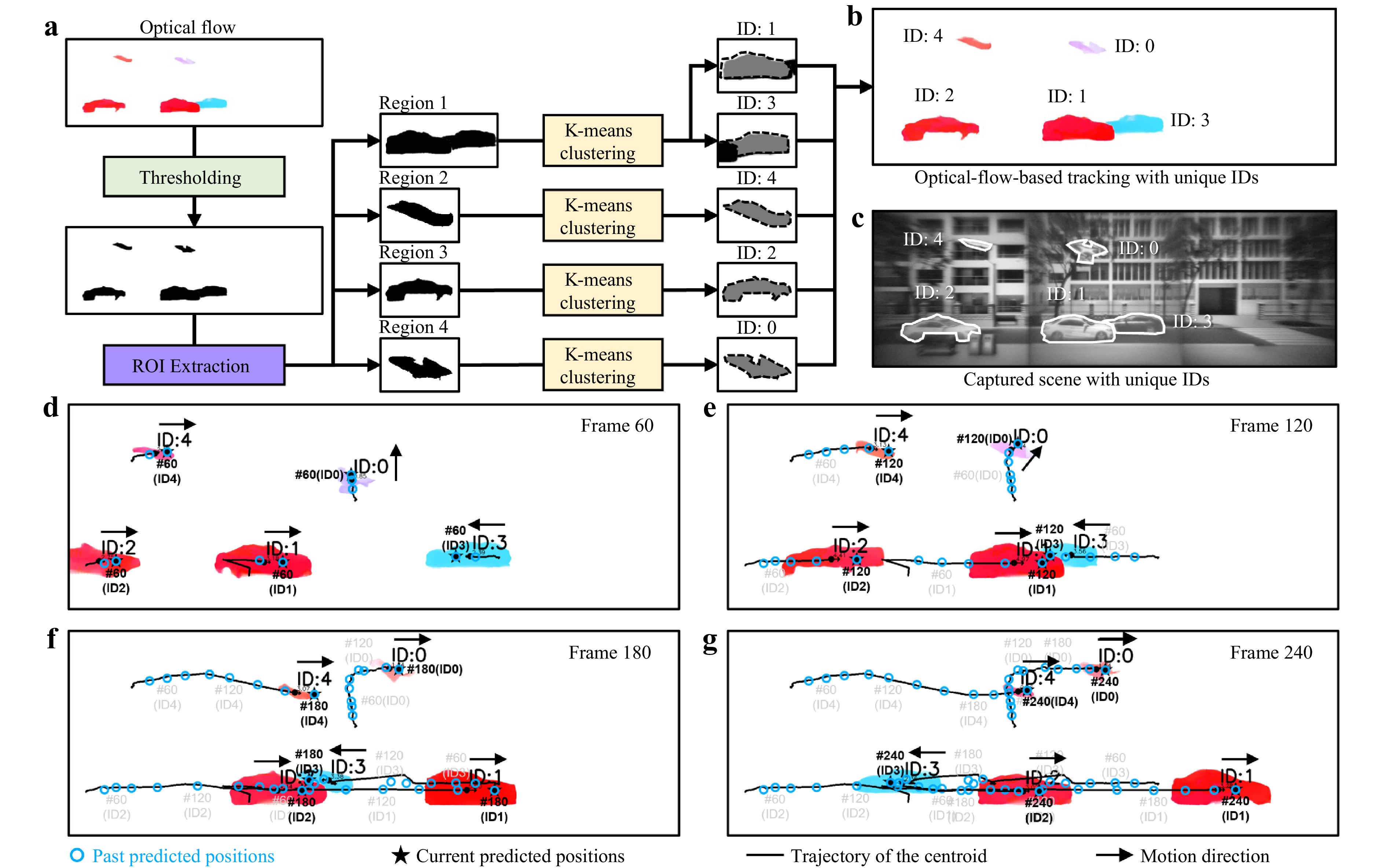
Fig. 6 Multi-object tracking and trajectory prediction using the MTP framework. a Processing flowchart of the multi-object tracking strategy using the MTP framework. b Multi-object tracking results with unique IDs using the MTP framework. c Manually annotated ground truth from the actual captured scene from PINS, showing a one-to-one correspondence with the IDs in (b). d-g Tracking and trajectory prediction results for multiple moving objects presented at frame 60, 120, 180 and 240 of the 300-frame sequence. The solid black lines represent the centroid trajectories of the objects. The hollow blue circles indicate historical predicted positions. The solid black stars mark the current predicted locations. The frame numbers corresponding to selected representative predicted positions are labelled nearby.
-
The functional advantages of the compound eyes of insects were emulated by integrating a well-designed metalens-array-based optical system with an MMS neural network. Building on this foundation, an MTP framework was introduced to enable intelligent trajectory forecasting. This biomimetic strategy enabled both ultrawide FoV imaging and accurate motion sensing and prediction within a compact platform. This wide-angle imaging capability is primarily determined by the hardware design of the metalens array, whereas the motion detection performance is influenced by a combination of factors including the imaging quality, temporal resolution, and accuracy of the optical flow estimation enabled by the MMS neural network. Several hardware-level improvements can be pursued to further enhance the motion sensing capabilities of the system. Employing high-performance CMOS sensors with smaller pixel sizes and faster frame rates can significantly improve spatial and temporal resolutions. Smaller pixels enable the detection of finer spatial displacements, whereas higher acquisition speeds allow the capture of subtle temporal variations in object motion. In addition, integrating faster CPUs or GPUs for downstream image processing can substantially accelerate the extraction of motion information from captured signals, enabling near-real-time motion analysis for dynamic scenes. This is particularly beneficial for scenarios involving sudden stops or sharp turns, where the prediction accuracy may otherwise temporarily decrease owing to abrupt deviations from the preceding motion trend. A higher frame rate can alleviate this limitation by reducing the interframe motion gap and improving the robustness of trajectory prediction in dynamic scenes. Meanwhile, real-time inertial data from the MAV can be used to estimate and remove the MAV-induced global flow component from the MMS-derived optical flow such that the residual flow mainly reflects the motion of independently moving objects in the scene. Furthermore, the robustness of the MTP framework can be improved in future studies for scenarios involving object crossing and partial occlusion46,47.
One of the key advantages of the proposed wide-angle imaging approach is the modular design of the metalens array in which each individual metalens is responsible for a specific angular FoV. This architecture enables not only flexible expansion of the overall imaging coverage by adding additional metalenses to the array to capture side-FoV scenes but also flexible control of the overlap between adjacent angular sectors through the design of the added linear tilt phases. Consequently, the system can be configured to provide either richer motion information redundancy or broader spatial coverage, depending on the application requirements, as illustrated in Supplementary Note S16. The challenge of reducing the light intensity at large off-axis angles can also be addressed in this metalens array design. The proposed method permits an increase in the aperture size of metalenses dedicated to wide-angle detection, thereby enhancing light throughput and mitigating intensity degradation. Another fundamental advantage of the proposed system is its ability to reliably detect and predict the motion of multiple dynamic objects across wide scenes. This is enabled by the MMS neural network for optical flow estimation and by the MPT framework for future trajectory prediction. This architecture allows for frame-by-frame tracking and future trajectory estimation of multiple targets simultaneously, even under challenging conditions, such as small size, slow motion, or visual blending with the background. Although the current horizontal FoV extension already meets the demands of most ground-based applications, such as autonomous driving and landscape surveillance, the viewing range can be further extended to two-dimensional coverage using a metalens array architecture, enabling near-omnidirectional angular observation. The binocular configuration of the system introduces additional functionality for depth-aware motion analysis. The detailed implementation and underlying principles of the stereo-depth extension are presented in Supplementary Note S17.
In conclusion, a planar intelligent nanophotonic sensor inspired by the compound eyes of insects was realized by combining hardware and algorithmic innovations to achieve precise motion state detection and intelligent trajectory prediction across ultra-wide-angle scenes. Through the optical flow generated by the neural network, the device enables precise motion state detection and subsequent trajectory prediction of moving objects across an ultrawide horizontal FoV of 135°. To ensure the effective training of the neural network, a PSF-based convolutional imaging model that enables the rapid generation of large-scale high-quality wide-angle scenes and optical flow data pairs was proposed. A well-trained neural network demonstrates exceptional accuracy and robustness in motion detection, enabling the precise tracking of minute displacements, small-scale targets, and motion under complex background conditions, which remains a challenge for conventional computer vision-based recognition approaches. The integration of the MPT prediction framework enabled the system to observe and track moving targets and accurately forecast their future positions. Owing to its compact size and lightweight design, the PINS is particularly well-suited for integration into MAVs, enabling agile and flexible deployment in dynamic environments. This significantly broadens the range of potential applications for autonomous driving and intelligent transportation systems. Equipped with a PINS, MAVs can perform real-time motion detection and trajectory prediction for vehicles and pedestrians, thereby facilitating informed decision-making and effective risk avoidance.
-
The phase profile of the central FoV metalens was determined by ray-tracing optimisation using Zemax. Six incident angles (0°, 4.5°, 9°, 13.5°, 18°, and 22.5°) were selected for the analysis to cover the designed central field of view. The metalens was modelled as a “Binary2” surface, with the phase profile described by an even-order polynomial $ \phi (r)=\sum\nolimits_{i=1}^{5}{a}_{i}\cdot {(r/R)}^{2i} $, where R is the metalens radius, r is the radial coordinate, and ai are the coefficients to be optimised. The optimisation objective was to minimise the focal spot size for the selected incident angles. Global optimisation in Zemax yielded the optimal coefficients a1 to a5 are −888.05, 4.73, 1.84, −1.35, and 0.0076, respectively. The phase profiles of the two side-FoV metalenses were subsequently generated by introducing tilt phases of ±kdsin45° to the centre-FoV metalens phase, enabling off-axis focusing. The corresponding ray-tracing verification of the focusing performance of metalenses with different FoVs is provided in Supplementary Note S2.
-
Metalens structures were fabricated using silicon nitride nanoparticles with a height of 1,000 nm and varying cross-sectional sizes. Through finite-difference-time-domain (FDTD) simulation, eight types of nano-posts were identified to cover the 2π phase range with high transmittance (>90%), and their diameters were 81, 110, 134, 153, 169, 184, 199, and 212 nm, respectively. The complete structural pattern was constructed by assigning appropriately sized nano-posts on a pixel-by-pixel basis, in accordance with the designed phase profile. For metalens fabrication, first, a 1,000 nm-thick silicon nitride layer was deposited on a SiO2 substrate via plasma-enhanced chemical vapour deposition (PECVD). Subsequently, a 225-nm PMMA A4 resist and 50-nm AR-PC 5090 conductive layer were spin-coated and exposed using an electron-beam lithography system (Elionix ELS-F125). After development (MIBK:IPA = 1:3, 120 s; IPA rinse, 60 s), a 40-nm Cr layer was deposited and patterned via lift-off to serve as a hard mask for the dry etching of silicon nitride. Finally, the sample was etched and the Cr mask was removed using ceric ammonium nitrate, yielding the final metalens structure on the substrate.
-
This study was supported by the National High-Level Personnel of Special Support, Basic Research Program of Jiangsu (No. BK20252002), Young Elite Scientists Sponsorship Program by CAST (No. 2022QNRC001), National Natural Science Foundation of China (Nos. 61960206005 and 61871111), and Jiangsu Key R&D Program Project (No. BE2023011-2), Fundamental Research Funds for the Central Universities (No. 2242022k60001), and the Project of the National Mobile Communications Research Laboratory (No. 2026A03).
Bioinspired planar intelligent nanophotonic sensor for wide-angle accurate motion perception and prediction
- Light: Advanced Manufacturing , Article number: 64 (2026)
- Received: 14 January 2026
- Revised: 02 April 2026
- Accepted: 13 April 2026 Published online: 15 May 2026
doi: https://doi.org/10.37188/lam.2026.064
Abstract: In nature, certain insects possess specialised compound eye structures that provide an ultra-wide field-of-view (FoV) and rapid response capabilities, enabling them to capture prey and avoid obstacles. Herein, inspired by compound eyes, a planar intelligent nanophotonic sensor (PINS) based on a metalens array, which possesses an ultrawide horizontal FoV exceeding 135°, is demonstrated. By leveraging a deep neural network, meta-motion sense (MMS), accurate optical flow can be extracted from PINS-captured wide-FoV scenes, enabling a comprehensive characterisation of the motion velocities and directions of all dynamic objects. Compared to traditional machine-vision-based object recognition algorithms, the proposed approach exhibits significantly higher accuracy and robustness, particularly in detecting small, slow, or background-blended moving targets, and offers an intelligent predictive capability for forecasting the motion trajectories of objects. The proposed device combines the advantages of high compactness, superior motion-detection performance, and intelligent functionality, offering a promising foundation for next-generation applications in autonomous navigation, situational awareness, and military surveillance.
Research Summary
Bioinspired Sensor: Wide-View Motion Sense
A sensor mimicking insect compound eyes, which uses a metalens array and an AI neural network to detect motion over an ultra-wide field of view, shows great promise for autonomous navigation, situational awareness, and military surveillance. Insects like dragonflies have compound eyes that provide wide viewing angles and high motion sensitivity, but mimicking these structures in man-made devices has long been challenging due to fabrication difficulties and bulky designs. Ji Chen from China's Southeast University and colleagues developed a planar sensor (PINS) with a horizontal view exceeding 135°; its AI system extracts precise motion details, including speed and direction, and outperforms standard machine-vision methods, even for small, slow-moving targets hidden in complex backgrounds. Lightweight and compact, it is easily deployable on mobile platforms like miniature drones.
Rights and permissions
Open Access This article is licensed under a Creative Commons Attribution 4.0 International License, which permits use, sharing, adaptation, distribution and reproduction in any medium or format, as long as you give appropriate credit to the original author(s) and the source, provide a link to the Creative Commons license, and indicate if changes were made. The images or other third party material in this article are included in the article′s Creative Commons license, unless indicated otherwise in a credit line to the material. If material is not included in the article′s Creative Commons license and your intended use is not permitted by statutory regulation or exceeds the permitted use, you will need to obtain permission directly from the copyright holder. To view a copy of this license, visit http://creativecommons.org/licenses/by/4.0/.

 DownLoad: