


-
The advent of the Fourth Industrial Revolution has catalysed a paradigm shift in traditional manufacturing industries towards intelligent manufacturing systems enabled by advanced digital and information technologies1. In this context, three-dimensional (3D) imaging and measurement techniques play a crucial role in providing full-field, accurate, and reliable geometric information for high-end precision manufacturing. These techniques can be equipped with machines with human-like 3D visual perception, enabling them to assist or even replace human operators in complex and extreme environments2–4. Therefore, 3D sensing facilitates automation, intelligence, and reconfigurability in intelligent manufacturing processes. In addition to manufacturing, numerous applications of 3D sensing are emerging in medicine5–7, dentistry8–10 and agriculture11–13.
As a typical non-contact 3D measurement technique, fringe projection profilometry (FPP) has been extensively used in inspection, manufacturing, and beyond owing to its strong performance in high-accuracy and high-speed 3D surface measurements14–16. Inspired by classical optical interferometry17–19 to modulate height with interference fringes, FPP simplifies the process by directly projecting computer-generated sinusoidal fringe patterns onto the object surface. The deformed patterns are captured by a camera from another view, and accurate 3D shape reconstruction can be achieved after fringe analysis and system calibration. This approach eliminates the need for coherent light sources or complex optical set-ups in interferometric methods, resulting in superior robustness and versatility for practical applications.
With advances in the current scientific and technological revolution, research frontiers are rapidly extending towards the extremes, which cover ultra-macroscopic scales, ultra-microscopic domains, and extreme environmental conditions. This evolution imposes rigorous requirements on traditional FPP techniques. The need to operate reliably under complex illumination conditions20,21, dynamic scenes22,23, materials with diverse reflective24–26 or absorptive properties27–29, and extreme temperatures30 highlights the importance of developing new theories, methods, and hardware systems that enhance adaptability and robustness. Addressing these emerging requirements is critical for advancing FPP into the next-generation 3D imaging technology to meet the demands of the forthcoming wave of industrial and digital transformation.
Over the past 40 years, vast advancements have emerged in the theory, techniques, and applications of FPP to meet the increasing demand for higher accuracy, speed, and applicability. According to the different targets and contributions, research on FPP can be divided into three phases: the foundation phase (1983–2006), the booming phase (2007–2018), and the transformative phase (2019–present). A roadmap for its development, including significant theoretical and technical breakthroughs and emerging trends for future directions, is summarized in Fig. 1.

Fig. 1 Roadmap of the development of FPP. (Reproduced with permission from Refs. [36], [16], [62], [140], and [325]. Copyright 2007, 2020, 2012, 2016, and 2018, Elsevier. Reproduced with permission from Refs. [78] and [139]. Copyright 2006 and 2014, SPIE. Reproduced with permission from Ref. [367]. Copyright 2021, IEEE. Reproduced with permission from Ref. [387]. Copyright 2026, Wiley-VCH.)
In the foundation phase (1983–2006), the studies were focused on establishing fundamental theories. As a pioneer, Takada et al. proposed Fourier transform profilometry (FTP) for the automatic measurement of 3D shapes in 198331. For the first time, they developed a computer-based automatic fringe analysis method32, which has been experimentally proven in both interferometry and profilometry31,33,34, opening the door to research on FPP in the next 40 years. Following FTP, other single-shot fringe analysis methods have emerged, including windowed Fourier transform profilometry (WFTP)35,36, wavelet transform profilometry (WTP)37,38, and S-transform profilometry (STP)39–42, to enhance noise robustness, time-frequency localization, and resistance to complex backgrounds. Point-to-point multiple-frame methods were also developed to deal with complex geometries with discontinuities and abrupt edges. In 1984, Srinivasan proposed automated phase-measuring profilometry (PMP)43 for 3D diffuse objects, in which the phase can be calculated pixel-by-pixel from a series of phase-shifting sinusoidal patterns, paving the way for further studies on high-accuracy 3D shape measurements. To solve the phase ambiguity problem caused by the inverse trigonometric operation, temporal phase unwrapping (TPU) algorithms44 were developed with PMP. The representative methods were the phase-based multi-frequency phase-shifting algorithm45–53 and the intensity-based Gray-coded-based algorithm54–62. Absolute and pixel-wise phase calculations were achieved using the TPU algorithm. Finally, calibration methods were presented to convert the phase distribution into 3D information, including the typical camera calibration method63–65, phase-to-height model66–71, photogrammetric-based model72, self-calibrating model73,74, and triangular stereo model75–79, guaranteeing accurate 3D reconstruction. In this phase, the fundamental theories and main framework for FPP were established, laying the foundation for further achievements.
In the booming phase (2007–2018), the studies were focused on improving measurement performance. Two core targets were pursued in this phase: higher measurement accuracy and speed. For high-accuracy measurements, researches took many efforts to overcome the problems caused by intensity noise44,80–84, illumination fluctuations85–89, phase-shifting errors90–97, non-linearity effects98–108, overexposure109–116 and binary defocusing117–125, pursuing the "perfect" sinusoidal fringes for optimal accuracy126. For high-speed measurement, two aspects are particularly critical. On the one hand, measurement and reconstruction should be performed simultaneously to meet the real-time requirements of applications such as online industrial inspection, virtual reality, and augmented reality. To this end, researchers have devoted their efforts to enhance the measurement efficiency and accelerate the computational process127–137. On the other hand, advanced hardware was employed to further boost system performance. Digital light processing (DLP) projectors138, array projection139, and "Goes Before Optics" (GOBO) projection140–143 were invented for faster and more flexible projections. High-speed cameras144, event cameras145–148, and single-photon avalanche diodes149–151 were developed for detection capabilities. In parallel, various fringe analysis algorithms152–155 were developed to fully exploit these hardware advances, significantly improving the measurement performance under challenging conditions. In this phase, various devices and techniques were thoroughly investigated, promoting the development of FPP and expanding their scope of applications.
In the transformative phase (2019–present), the studies are focused on breakthroughs in 3D imaging frameworks. In the booming phase, the low-hanging fruits have already been picked, and what remains cannot be easily solved using the traditional FPP framework. Deep learning, driven by the availability of massive datasets, has become a powerful tool for addressing inverse problems in different applications156–168. In 2019, Zuo et al. introduced deep learning in FPP and developed a deep-learning-based fringe pattern analysis technique to achieve multi-frame phase-shifting accuracy with single-frame phase demodulation169. This breakthrough marked a watershed moment in the field of FPP. This development transformed conventional FPP techniques, shifting the underlying framework from geometric optics-based physical modelling to a data-driven learning paradigm. Subsequently, numerous deep learning-based methods have been developed to renew each step in the traditional FPP framework, including fringe analysis170–174, phase unwrapping175–180 and error compensation181–187. The powerful inverse problem-solving ability of data-driven methods provides superior and efficient solutions for emerging challenges under imperfect measurement conditions compared with traditional knowledge-based methods. Data-driven methods are used to solve the longstanding contradiction between the measurement efficiency and performance in FPP. What was once a trade-off is now simultaneously achieved. However, there is no such thing as a free lunch. Great performance comes at the cost of large amounts of experimental data with labels and the risk of errors owing to a lack of interpretability. Therefore, researchers have sought to address these difficult problems by establishing new computational imaging models. The inherent "point-to-point" imaging model and "phase-based" error model limit the performance of FPP in extreme or imperfect environments. In 2021, Jiang et al. proposed parallel single-pixel imaging (PSI) for 3D shape measurement by introducing "point-to-plane" imaging framework188. With this brand-new computational architecture, the measurement of mixed scenes with multi-type reflection, including diffuse surfaces, inter-reflection, sub-surface scattering, and overexposed surfaces, can be simultaneously achieved. Subsequently, Wu et al. established a comprehensive theoretical model for PSI189, elucidating the intrinsic factors contributing to the universality and robustness of the method. Furthermore, key challenges, such as the low encoding efficiency of basis patterns and difficulty in principal component localization, were effectively addressed190. These developments reduce the practical implementation barrier of PSI and make this technology broadly accessible.
In this phase, the fundamental framework and underlying principles of FPP have undergone a profound transformation. The community has increasingly abandoned strict adherence to traditional triangulation and has gradually shifted towards a computational 3D imaging framework driven by artificial intelligence (AI) and computational imaging (CI) techniques. Furthermore, CI will yield higher-dimensional models that better represent physical systems, whereas AI will offer immense processing power to enhance performance beyond the current capabilities. These developments gradually redefine the rules of FPP, enabling superior accuracy, robustness under extreme conditions, and an expanded application scope.
The remainder of this paper is organised as follows. Section 2 outlines the classification and fundamental principles of FPP. Section 3 reviews the foundation phase, tracing its historical developments and early implementation procedures. Section 4 details the period of rapid expansion and application growth. Section 5 focuses on the recent breakthroughs and emerging research trends. Section 6 discusses the current challenges and outlines potential future perspectives. Finally, Section 7 concludes the paper with a summary of key findings and insights.
-
The fundamental principle of FPP is straightforward, yet highly effective: a carefully designed fringe pattern is projected onto the surface of the target object, and a camera records the deformed fringes caused by the surface geometry of the object from a different angle. By analysing how these fringes are distorted, it is possible to accurately reconstruct the 3D shape of an object with high precision and resolution.
Traditional FPP typically refers to a measurement technique that determines the phase from deformed patterns using different fringe analysis methods. However, with the increasing demand for higher measurement speeds and general solutions in different environments, the intensity-based and computational 3D imaging methods based on fringe projection have been gradually developed. In this review, we extend the concept of FPP to the generalized fringe projection approach, which encompasses all structured light measurement methods and systems that perform 3D reconstruction by projecting sinusoidal fringe patterns. Depending on the fringe analysis and processing strategy, these methods can be categorized into three classes (phase-based 3D imaging, intensity-based 3D imaging, and computational 3D imaging), as shown in Fig. 2a. The following paragraphs present the fundamental principles of each technique in detail.
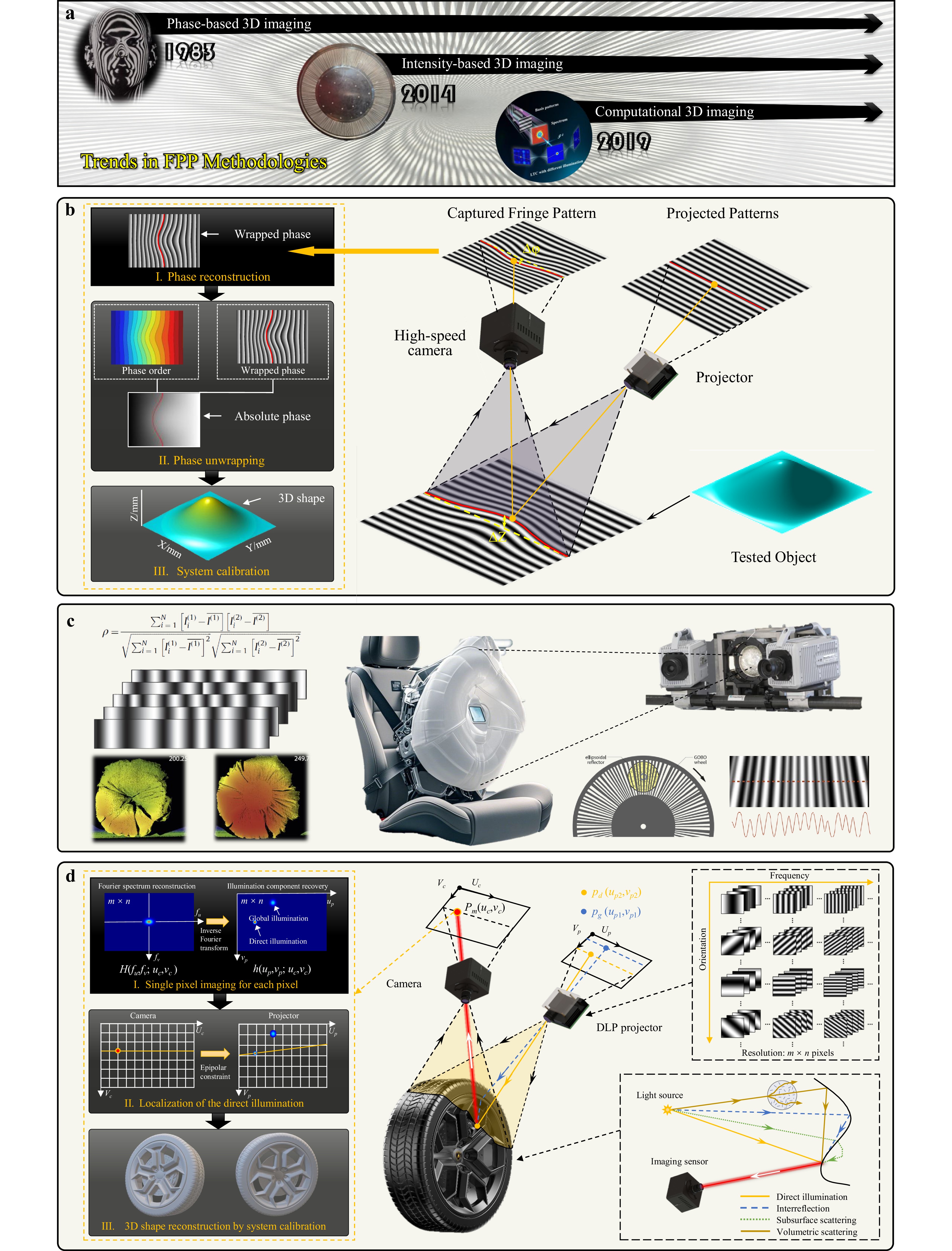
Fig. 2 Classification and fundamental principles of FPP. a Three categories of FPP: phase-based, intensity-based, and computational 3D imaging. b Phase-based 3D imaging. c Intensity-based 3D imaging. d Computational 3D imaging.
The phase-based 3D imaging technique, whose origins can be traced back to 198331, represent the earliest form of FPP. Sinusoidal patterns are projected onto the tested surface as described in Eq. 1, and the camera captures the deformed images from another angle, as shown in Fig. 2b. Fringe analysis methods, including single-shot34 or multi-shot approaches191 have been applied for phase reconstruction. A representative phase-shifting algorithm is used as an example to illustrate the measurement process, as shown in Eq. 2. Other phase-analysis methods are introduced in Section 3.1. Because the arctangent function is involved in phase reconstruction, the calculated phase is inherently constrained to the range (−π, π], which is named the wrapped phase φ(x, y). To obtain a true continuous phase distribution that reflects the actual surface height, phase unwrapping must be performed to remove discontinuities and recover the absolute phase Φ(x, y), as described in Eq. 3. Finally, system calibration, including phase-to-height mapping and camera calibration, is performed to convert the phase information into 3D coordinates in the physical world.
$$ I_{i}^{Ph}(x,y)=A(x,y)+B(x,y)\cos [\varPhi (x,y)-{\delta }_{i}],i=1,2,3...N $$ (1) $$ \phi (x,y)=\mathrm{artan}\left[\frac{\sum _{i=1}^{N}(I_{i}^{Ph}(x,y)\sin {\delta }_{i})}{\sum _{i=1}^{N}(I_{i}^{Ph}(x,y)\cos {\delta }_{i})}\right] $$ (2) $$ \varPhi (x,y)=\phi (x,y)+2{\text{π}} k(x,y) $$ (3) Intensity-based 3D imaging techniques have been developed to overcome the effects of phase-based errors. Instead of projecting phase-shifting patterns with temporally varying statistical patterns, $ I_{1}^{In},\ldots I_{N}^{In} $ are projected onto the measured surfaces, as described in Eq. 4, and observed using two cameras, as shown in Fig. 2c192–195. At each image point (x(1), y(1)) in camera 1, a temporal grey sequence $ I_{1}^{In(1)},\ldots I_{N}^{In(1)} $ is obtained and correlated with the grey sequence $ I_{1}^{In(2)},\ldots I_{N}^{In(2)} $ captured by camera 2 using Eq. 5. Corresponding points can be found by maximizing the correlation coefficient ρ. If the system parameters are obtained via calibration, the 3D shape can be calculated via triangulation of the corresponding points196. Here, aperiodic sinusoidal fringe patterns are projected according to Eq. 4.
$$ I_{i}^{In}(x,y)={a}_{i}(x)+{b}_{i}(x)\cos [{\mathrm{c}}_{i}(x)x+{d}_{i}(x)],i=1,2,3...N $$ (4) $$ \rho =\frac{\sum \nolimits_{i=1}^{N}[I_{i}^{In(1)}-\overline{I_{}^{In(1)}}][I_{i}^{In(2)}-\overline{I_{}^{In(2)}}]}{\sqrt{\sum \nolimits_{i=1}^{N}{[{I_{i}^{In(1)}}-\overline{I_{}^{In(1)}}]}^{2}}\sqrt{\sum \nolimits_{i=1}^{N}{[{I_{i}^{In(2)}}-\overline{I_{}^{In(2)}}]}^{2}}} $$ (5) Compared with traditional phase-based 3D imaging methods, the intensity-based approach does not require prior knowledge of the projected statistical patterns, thereby significantly relaxing the constraints on the temporal variation of patterns and system synchronization. Without the need for phase shifting, this approach is particularly well suited for ultra-high-speed 3D measurements, as elaborated in Section 4.2.3.
Computational 3D imaging has emerged with the rapid development of AI and CI technologies. Traditional approaches are often unable to resolve the trade-offs between measurement efficiency and performance. In addition, conventional FPP methods typically follow a point-to-point triangulation principle, and therefore, they face limitations when dealing with complex scenes containing mixed global illumination components, such as inter-reflection, sub-surface scattering, and saturation. Data-driven AI-based methods and physics-informed CI-based architectures have gained popularity to overcome these limitations.
As a representative example, the parallel single-pixel 3D imaging technique proposed by Jiang et al. in 2021188, illustrates the ingenious concept of computational 3D imaging, as shown in Fig. 2d. In this approach, each camera pixel (uc, vc) is treated as an independent single-pixel detector, and a Fourier single-pixel imaging algorithm197 is applied to each pixel to separate the global illumination components. This is achieved by projecting fringe patterns with varying spatial frequencies and orientations, as described in Eq. 6, where fu and fv denote the frequency components of the projected patterns along u and v directions, respectively. Without a collecting lens in the camera, the reconstructed single-pixel image directly reveals the spatial distribution of all the illumination components from the view of the projector for each camera pixel. These reconstructed intensities are defined as light transport coefficients (LTCs) h(up,vp;uc,vc), which are used to describe and separate the mixed illumination components. h(up,vp;uc,vc) is computed via Fourier spectrum reconstruction, followed by an inverse Fourier transform, as expressed in Eqs. 7, 8, respectively. By incorporating epipolar constraints, the direct illumination can be accurately localized. Finally, a stereo vision algorithm is applied to reconstruct the 3D coordinates using the known positional correspondence between the projection and camera planes.
$$\begin{split}& I_{{}_{i}}^{Comp}({f}_{u},{f}_{v};{u}_{c},{v}_{c})=A({u}_{c},{v}_{c})+\sum \limits_{{v}_{p}=0}^{L-1}\sum \limits_{{u}_{p}=0}^{K-1}h({u}_{p},{v}_{p};{u}_{\mathrm{c}},{v}_{c})\\&\quad\left\{a+b\cos [2{\text{π}} ({f}_{u}{u}_{p}+{f}_{v}{v}_{p})+{\delta }_{i}]\right\} \end{split}$$ (6) $$\begin{split}H({f}_{u},{f}_{v};{u}_{c},{v}_{c})=\;&\left[\sum \limits_{i=1}^{N}I_{{}_{i}}^{Comp}({f}_{u},{f}_{v};{u}_{c},{v}_{c})\cos {\delta }_{i}\right]\\&+j\left[\sum \limits_{i=1}^{N}I_{{}_{i}}^{Comp}({f}_{u},{f}_{v};{u}_{\mathrm{c}},{v}_{c})\sin {\delta }_{i}\right]\end{split} $$ (7) $$ h({u}_{p},{v}_{p};{u}_{c},{v}_{c})=\frac{2}{Nb}\cdot {F}^{-1}[H({f}_{u},{f}_{v};{u}_{c},{v}_{c})] $$ (8) In summary, phase-based, intensity-based, and computational 3D imaging methods represent the three principal categories of FPP techniques. Each provides a distinctive strength. Phase-based methods encode the depth information through precise phase modulation and reconstruction. They are inherently robust to intensity variations and moderate noise in the measurement environments. However, their accuracy strongly depends on the precision of the phase reconstruction, which imposes stringent requirements on the projector and camera imaging quality, synchronization accuracy, and system linearity. In contrast, intensity-based methods introduce a stereo imaging framework in which the projected patterns mainly serve as correspondence markers rather than precise phase carriers. By relying on temporally varying intensity sequences instead of phase shifting to establish unique matching features, these methods significantly relax the demands for pattern stability and modulation precision, allowing the use of faster but potentially less stable devices for ultra-high-speed 3D measurements. Nevertheless, conventional FPP techniques, including both phase-based and intensity-based approaches, generally follow a point-to-point triangulation principle and thus encounter difficulties in complex scenes with mixed global illumination effects such as inter-reflection, sub-surface scattering, and saturation. Computational 3D imaging addresses these limitations by incorporating additional priors, either data-driven or physics-informed, and by adopting higher-dimensional imaging architectures beyond traditional triangulation. Hence, it enables a more robust and accurate reconstruction under complex reflective and transmissive conditions. Overall, phase-based methods are best suited for high-precision measurements in stable environments, intensity-based methods are advantageous for high-speed measurement under noisy or dynamic conditions, and computational 3D imaging is particularly effective for high-precision reconstructions under abnormal illumination conditions.
The evolution of these three approaches has shaped the development trajectory of FPP over the past four decades, guided its technological progress, and broadened its application landscape.
-
In the foundation phase (1983–2006), studies were primarily focused on establishing the fundamental theories of FPP. During this period, various techniques were developed to satisfy different measurement requirements. For example, FTP was proposed for dynamic measurements, whereas PMP was developed for high-accuracy measurements. The central efforts of this phase were concentrated on phase-based 3D measurement methods, which were categorized into different strategies for phase reconstruction and phase unwrapping, as illustrated in Fig. 3a. It shall be highlighted that this classification does not cover all existing FPP approaches, and in this review, we selectively highlight the representative and widely adopted methods. By tracing these key techniques and their underlying principles, we aim to provide readers with a clear understanding of how FPP has progressed from its theoretical foundation to its early practical application. These contributions laid the foundation for future innovations and breakthroughs.
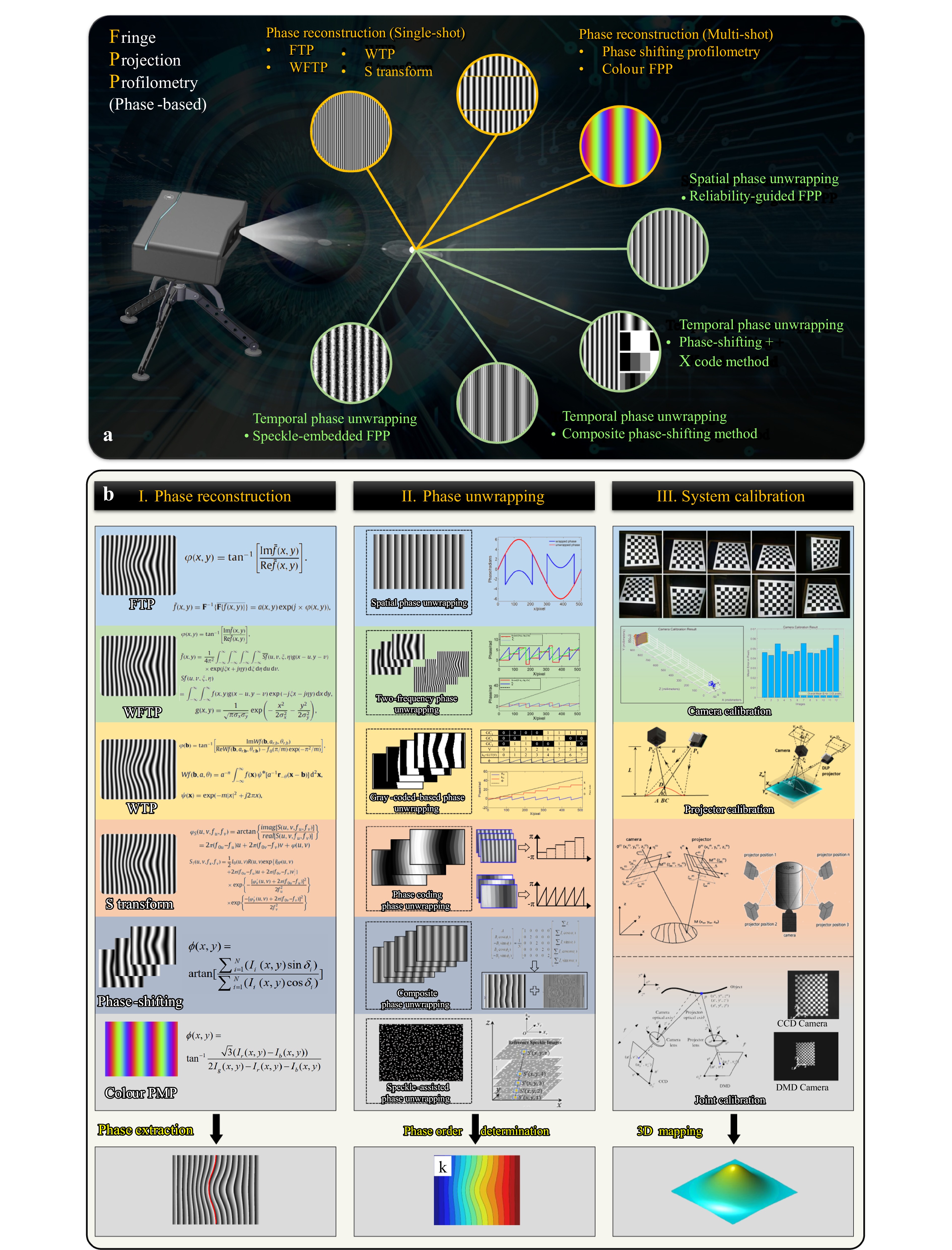
Fig. 3 Historical developments and implementation procedures of phase-based FPP in the foundation phase (1983–2006). a Classification of representative phase-based 3D measurement methods according to phase extraction and phase unwrapping strategies. b Typical pipeline of phase-based FPP, consisting of phase reconstruction, phase unwrapping, and system calibration. (Reproduced with permission from Refs. [74] and [78]. Copyright 2000 and 2006, SPIE.)
Although the theoretical foundation of phase-based FPP appears simple, its practical implementation requires a series of well-designed steps to achieve an accurate and reliable 3D reconstruction. The phase-based FPP framework consists of three key stages, namely, phase reconstruction, phase unwrapping, and system calibration, as shown in Fig. 3b. Each of these steps plays an important role in 3D reconstruction. In the following sections, we discuss the major advances in each stage, highlighting the representative methods, their underlying principles, and their impact on the development of FPP. The categories and comments on the representative phase-based FPP methods are summarized in Table 1.
Category Strategy Representative method Reference Remarks Phase reconstruction Single-shot FTP Takeda and Mutoh31 (1983-) Efficient for dynamics but trade noise sensitivity for robustness as evolving from global to localized and hybrid approaches. WFTP Qian. 35 (2004-) WTP Sandoz37 (1997-) S-transform Mansinha et al.42 (1997-) Multi-shot PMP Srinivasan et al.43 (1984-) Provide high accuracy and robustness with strong noise resistance, but require multiple projections and are less suited for dynamic scenes. Colour PMP Huang et al.198 (1998-) Phase unwrapping Spatial phase
unwrappingPath-dependent methods Goldstein et al.199 (1988-) Enable flexible reconstruction but are highly sensitive to noise, shadows, and undersampling. Path-independent approaches Bone200 (1991-) Dynamic 3D spatial unwrapping Zhang et al.201 (2006-) Temporal phase unwrapping Multi-frequency phase-shifting Huntley and Saldner48 (1993-) Ensure global consistency and robustness for complex surfaces but require multiple projections that limit dynamic performance. Gray coding Inokuchi202 (1984-) Gray-level coding Ito and Ishii203 (1995-) Phase coding Wang and Zhang204 (2012-) System calibration Camera calibration Tsai's camera calibration Tsai65 (1987-) Simple and accurate but dependent on 3D physical targets.The standard choice due to their high accuracy, ease of use, and adaptability. Zhang's camera calibration Zhang63 (2002-) Projector calibration Phase-to-height model Takeda and Mutoh31 (1983-) Stable accuracy in controlled set-ups but needs displacement mechanism. Inverse camera calibration Zhang and Huang78 (2006-) Simple calibration workflow and compatibility with widely available computer vision toolkits. Joint calibration Self-calibration Tian et al.205, Xiao et al.206 (2008-) Flexible target-free adaptability but with higher computational cost. Xiao et al.206 (2013-) Schreiber and Notni74 (2000-) Triangular stereo calibration Bouguet207 (2004-) Convert the problem into a generic binocular stereo calibration. Table 1. Summary and comments on the representative phase-based FPP methods.
-
Phase reconstruction is the cornerstone of FPP because it directly determines how effectively the captured fringe patterns can be translated into an accurate 3D surface profile. Over the past few decades, a variety of phase reconstruction techniques have been developed to improve the ability of FPP for more complex surfaces, diverse measurement conditions, and increasingly stringent accuracy requirements.
-
Single-shot fringe analysis methods differ primarily in how they extract the phase information embedded in the captured fringe patterns. The phase that carries the depth information must be retrieved precisely to ensure the measurement accuracy. To this end, researchers have developed several representative algorithms, such as FTP31–34, WFTP35,36, WTP37,38, and STP39–41. The FTP, introduced in the early 1980s, whose key idea is to treat the captured fringe pattern as a carrier signal modulated by the object's surface, is shown in Fig. 4. By transforming the image into the frequency domain using a one-dimensional (1D)31 or two-dimensional (2D)208 Fourier transform, the fundamental frequency component containing phase information can be separated from the background and noise using a 1D or 2D filter. The filtered signal is then inversely transformed back into the spatial domain to obtain the wrapped phase. FTP is highly efficient and well suited for snapshot measurement tasks, making it valuable for dynamic or transient phenomena.
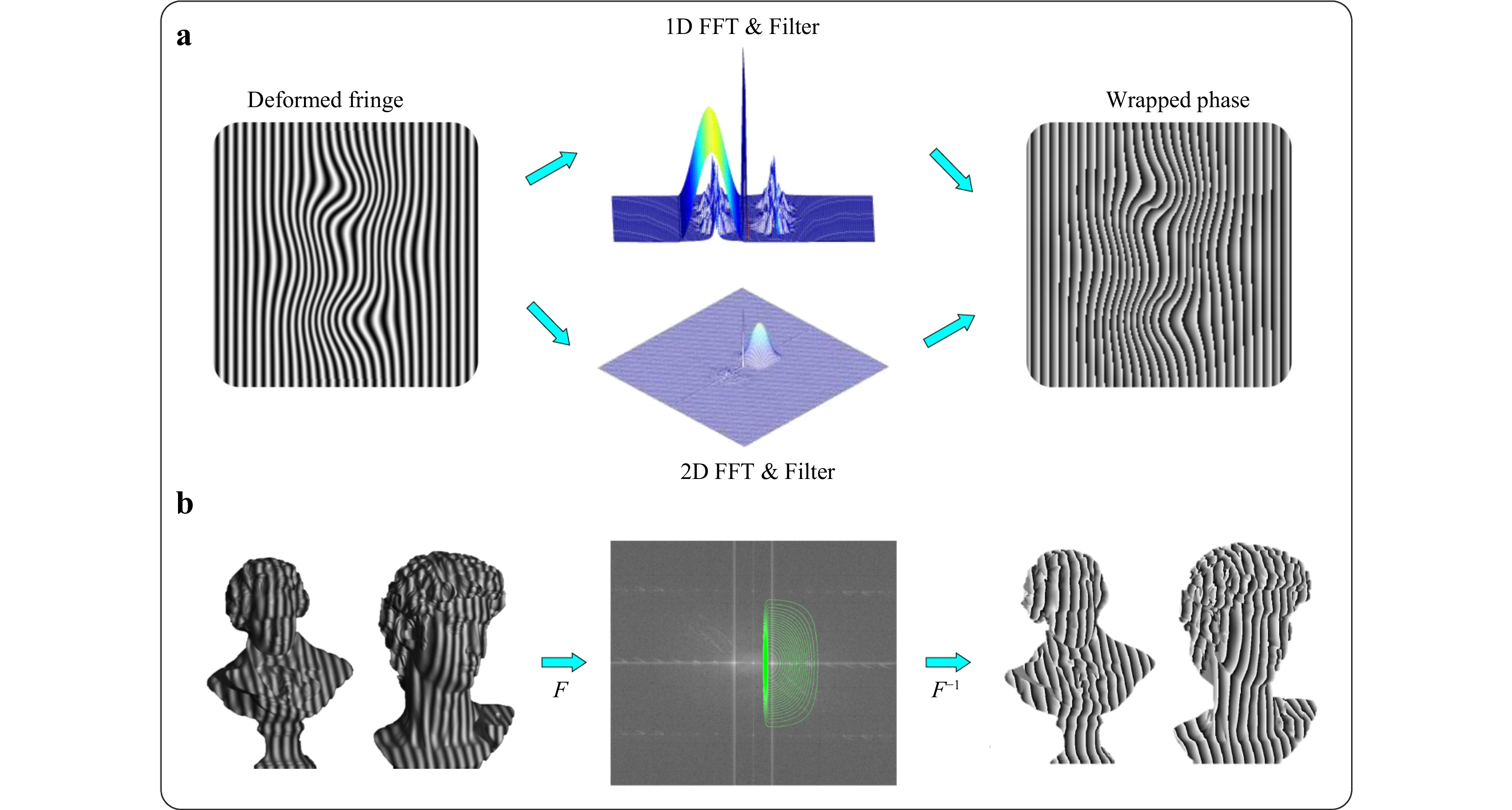
Fig. 4 Basic illustration of the FTP algorithm. a Algorithm workflow. b Measurement example.
Although it is highly efficient and suitable for single-shot measurements, its global nature makes it sensitive to background illumination and low-frequency variations. To overcome these issues, WFTP was introduced by Qian using localized windowing35,36 with adaptive filtering. This improved the measurement robustness of surfaces with fine features or discontinuities. Based on localized analysis, the WTP employed multi-scale wavelets37,38 to offer flexible resolution. The WTP could capture both the global shape and fine details and efficiently suppresses noise in textured or rough surfaces. The STP emerged as a hybrid approach39–41 and combined the adaptive localization of wavelets with the straightforward extraction of Fourier methods. This enhanced the accuracy under complex reflectance conditions and provided a practical balance between precision and computational efficiency.
In summary, these single-shot phase reconstruction techniques illustrate a clear evolution from global to local and hybrid approaches. From classic global transforms to advanced localized, multi-scale, and hybrid designs, they form a systematic framework for phase extraction in diverse scenarios. For a more detailed comparison of these single-frame phase reconstruction algorithms, readers can refer to the comprehensive review by Huang et al.209.
-
Parallel to the transform-based family of methods, phase-shifting techniques represent another cornerstone of phase reconstruction43. In contrast to FTP and its variants, phase-shifting methods rely on the projection of multiple fringe patterns with known phase differences. By capturing a sequence of images and applying point-wise trigonometric calculations, the wrapped phase can be retrieved directly with a high signal-to-noise ratio (SNR) and minimal spectral leakage. The classic N-step phase-shifting approach (e.g., 3-step or 4-step) is straightforward and robust; however, it requires the object to remain static during the measurement sequence. Fig. 5 shows the procedure of the standard 3-step phase-shifting approach in which the wrapped phase, average value, and modulation can be solved using sinusoidal patterns.
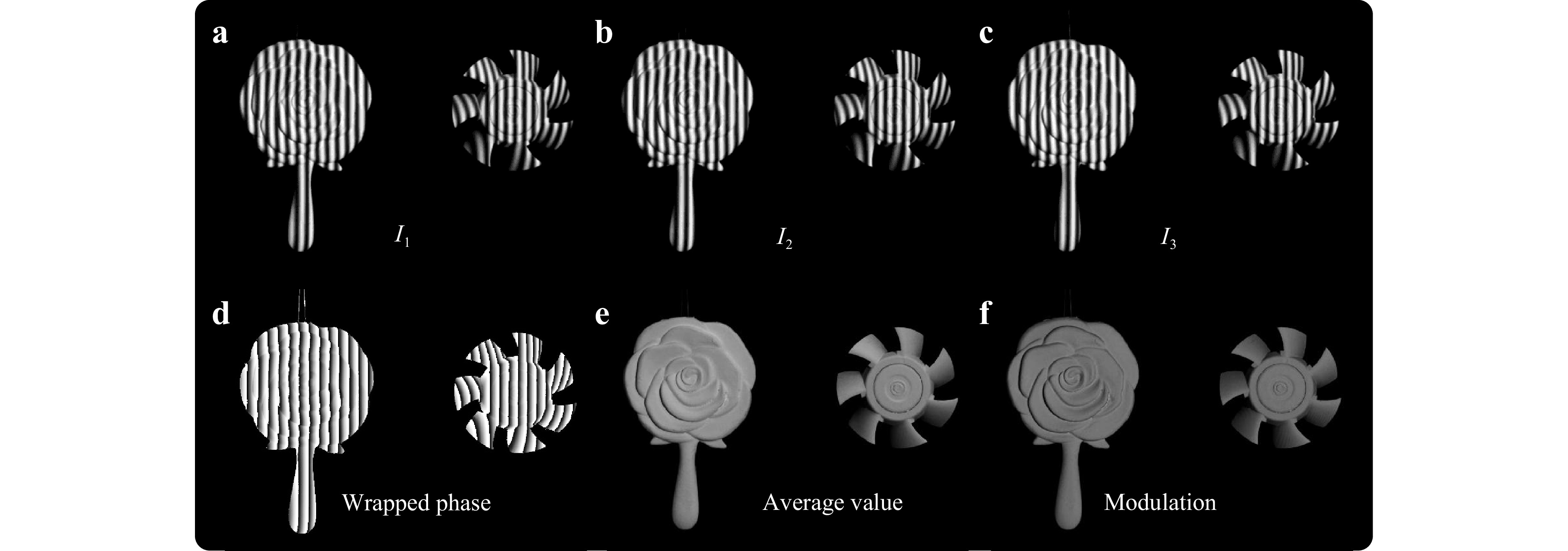
Fig. 5 Basic illustration of the PMP algorithm. a-c Phase-shifting sinusoidal patterns. d Wrapped phase. e Average value. f Modulation.
Various modified algorithms have been proposed to address these practical limitations. For example, the double 3-step method suppresses the phase-shifting errors, non-linearity, and intensity noise210. The Hariharan 5-step algorithm ensures robustness under unknown but constant phase shifts90. The modified 2 + 1 method alleviates motion artefacts by combining two phase-shifting patterns with a flat image211. In addition, the colour FPP encodes different phase steps into separate red-green-blue (RGB) channels, enabling single-shot phase reconstruction with phase-shifting accuracy153,198,212-216. For a more detailed comparison of these multi-shot phase reconstruction algorithms, readers can refer to the comprehensive review by Zuo et al.44.
-
Although phase reconstruction algorithms produce wrapped phase maps containing the essential shape information, the phase values are inherently limited within (−π, π], leading to phase ambiguities. These ambiguities reflect mathematical uncertainties rather than real surface discontinuities. To avoid these ambiguities, phase unwrapping is required to reconstruct a unique and continuous absolute phase map.
To address this challenge, numerous phase unwrapping methods have been developed that exploit different coding or projection strategies. These methods have significantly evolved in parallel to address specific measurement scenarios and constraints. We briefly introduce several representative and widely used approaches in the following sub-sections.
-
Spatial phase unwrapping methods reconstruct the absolute phase by integrating the phase differences between neighbouring pixels, as shown in Fig. 6a. A classical condition, derived by Itoh in 1982217, states that if the true phase difference between adjacent pixels is within ±π, then the wrapped and true differences coincide. However, in practice, noise, shadows, and undersampling often disobey this condition, which will cause unwrapping errors depending on the propagation path, as shown in Fig. 6b. Consequently, two broad categories of spatial phase unwrapping algorithms have emerged: path-dependent and path-independent strategies.
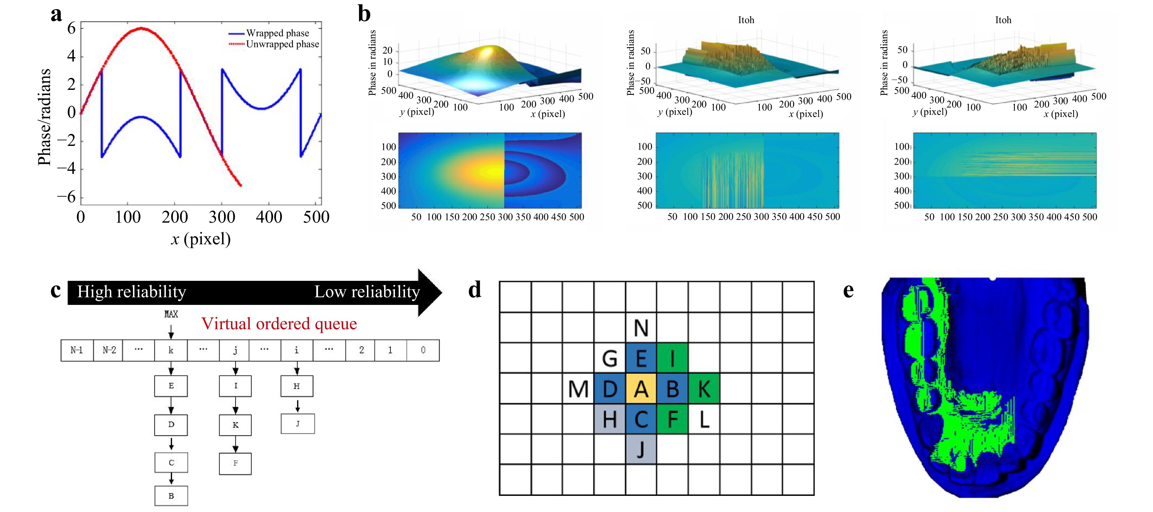
Fig. 6 Spatial phase unwrapping methods. a Basic principle of spatial phase unwrapping. b Errors caused by noise, shadows, or undersampling. c-e Representative quality-guided strategies based on reliability guidance.
Path-dependent methods rely on predefined propagation rules to prevent accumulation of errors in unreliable regions. The most notable method is the branch-cut method199 introduced by Goldstein, which identifies phase residues and connects them with cuts to prevent error propagation. Although effective, branch cuts may form isolated regions, resulting in incomplete unwrapping. Numerous improvements have been proposed to solve this problem, including residue cancellation218, optimized search windows219, and adaptive cut connection strategies220. Another influential category is quality-guided unwrapping200, where pixels are ranked by reliability metrics such as modulation, phase derivative variance, or gradient magnitude. High-quality pixels are unwrapped first, and low-quality pixels are processed later, which avoids error propagation, as shown in Fig. 6c-e. Quality-guided unwrapping is widely adopted for the measurement of complex geometries such as gypsum dental casts and additive manufacturing of structural components.
Path-independent approaches treat unwrapping as a global optimization problem. The least squares method200 minimizes the squared error between the wrapped and reconstructed gradients, producing smooth solutions that are sensitive to noise. Variants with binary masks or direct fringe-order estimations have improved the accuracy and stability. The minimum discontinuity method221, based on L1 norm minimization, instead seeks to minimize phase discontinuities across the entire field and has been refined with edge detection222, tabu search223, and quality-guided heuristics224 to better handle noisy or undersampled data.
In addition to the 2D cases, spatial unwrapping has been extended to dynamic 3D measurements by treating a sequence of wrapped phases as 3D fields. Methods such as residue-ring identification218, quality-guided extension225, region-merging optimization226, and fast 3D unwrapping 227 have been developed to ensure both spatial and temporal continuity. These advances highlight the transition of spatial unwrapping from heuristic path-tracking schemes to mathematically rigorous, optimization-based, and multi-dimensional solutions. For more details on spatial phase unwrapping algorithms, readers can refer to the reviews by Su and Chen228 and Zhao et al.224.
However, spatial unwrapping is highly sensitive to noise, shadows, and undersampling, making the reconstruction path-dependent and error-prone, which motivates the development of temporal phase-unwrapping methods as a more robust alternative.
-
Temporal encoding methods resolve phase ambiguities by sequentially projecting multiple fringe patterns using different frequencies or coding strategies. Unlike spatial unwrapping, which propagates the phase locally and is sensitive to noise or undersampling, temporal strategies determine the absolute fringe order pixel-by-pixel. Therefore, these methods ensure global consistency and higher robustness for complex or discontinuous surfaces.
Most temporal encoding methods can be summarized as the phase-shifting plus X-code, where the "X" represents an auxiliary coding scheme designed to determine the absolute fringe order. Depending on the coding design, X can correspond to multi-frequency phase shifting45–53, Gray coding54–62, Gray-level coding229–231, or phase coding204,232–237.
Multi-frequency phase shifting exploits the difference between wrapped phases at different spatial frequencies. These variants include hierarchical unwrapping48,50, number-theoretical approaches45,46,49 and heterodyne strategies47,238. Different strategies for frequency combinations were adopted in these three methods, leading to different performances in terms of anti-noise ability and resistance to motion. All of these methods can achieve efficient unwrapping with relatively few patterns, making them suitable for dynamic scenes.
Gray-coded phase unwrapping combines binary Gray patterns with sinusoidal fringes to provide absolute fringe order. An example of a typical complementary Gray code62 is shown in Fig. 7. Phase-shifting fringe patterns are used to calculate the wrapped phase, and Gray code patterns with unique encoding methods are projected to label each fringe order. An additional complementary Gray code is projected to avoid jump errors. Because of the low bit error rate of the Gray code, it is particularly effective for handling large discontinuities or isolated regions with high-level noise. However, its drawback is the large number of projected frames, which limits its dynamic performance. To improve speed, Gray-level coding extends binary Gray codes to multi-level intensity patterns for measurements using fewer patterns229,230. However, this method is more susceptible to noise owing to the smaller greyscale transitions. Phase coding has emerged as another efficient alternative because it encodes fringe-order information directly into the phase domain204. This enables the simultaneous reconstruction of the wrapped phase and fringe order from the phase-shifting fringes. This reduces the number of projection patterns while maintaining robustness.
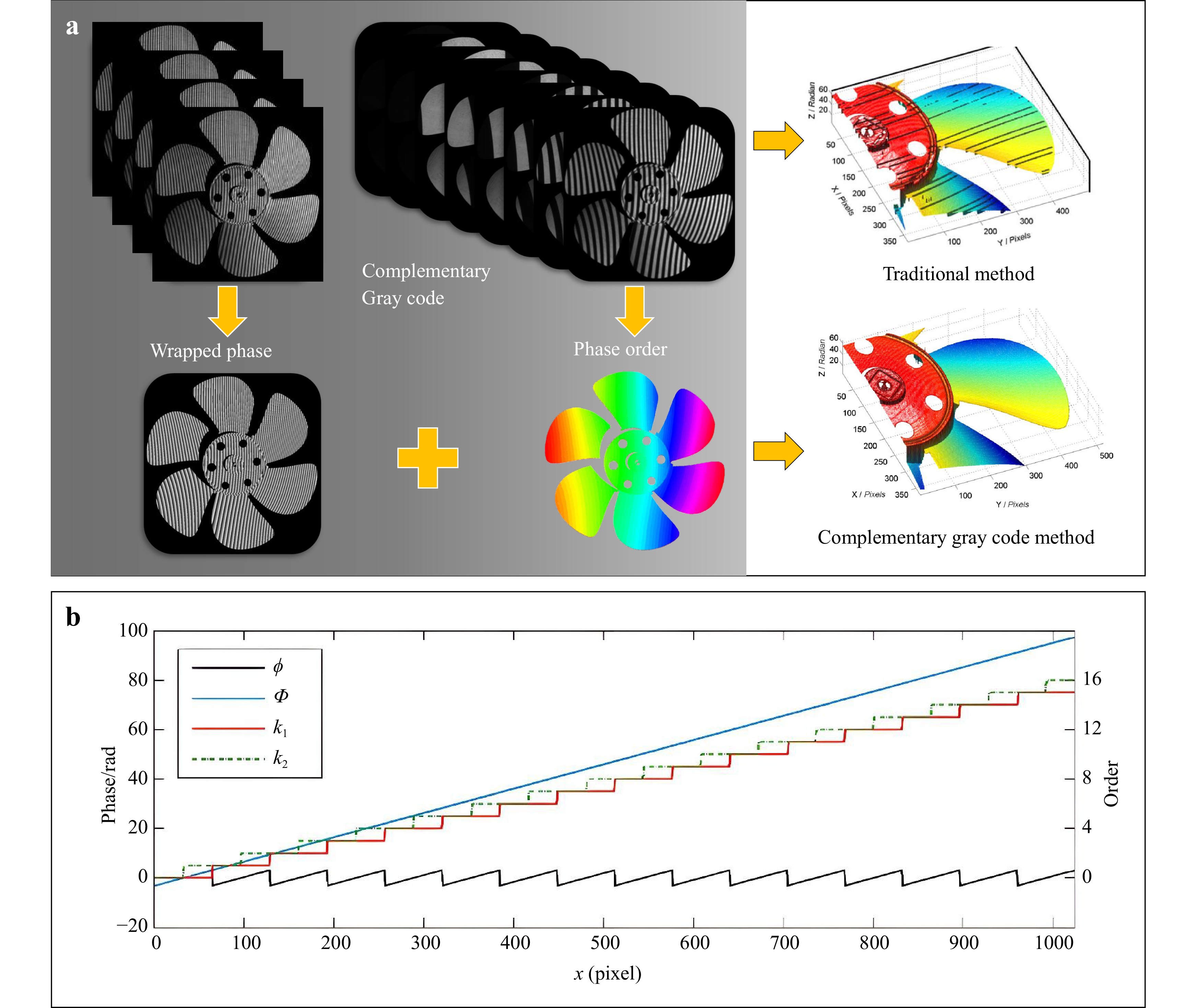
Fig. 7 Temporal phase unwrapping. a Process and results of traditional method and complementary Gray code method. b Illustration of complementary Gray code unwrapping for resolving phase-order jumps.
Temporal encoding methods also explore the idea of embedding multiple codes, colours, speckles, or different frequencies into the projected pattern to improve the encoding efficiency and resistance to noise. Representative examples include the composite phase-shifting method179, colour fringe projection198, and speckle-embedded FPP239. These methods aim to capture richer information within fewer frames. This is particularly valuable for dynamic scenes in which motion artefacts dominate the measurement quality. For a more detailed comparison of these temporal phase-unwrapping algorithms, readers can refer to comparative reviews by Zuo et al.44, He and Qian240, and Wu et al.241.
-
System calibration is the final step in FPP and directly influences the accuracy and repeatability of 3D surface reconstruction. The primary goal is to establish an accurate geometric mapping of the camera, projector, and measurement space. Therefore, system calibration is the last but most important step. Over the years, multiple calibration models have been developed and optimized for specific requirements and loose practical constraints in FPP applications.
-
Camera calibration aims to establish an accurate geometric relationship between the camera and physical world. Camera calibration is a fundamental step to determine the intrinsic and extrinsic parameters of the imaging system. In 1987, Tsai proposed a two-step method based on radial alignment constraint (RAC)65. It is a pioneering work that involves obtaining initial estimates using a linear algorithm and then optimizing them through non-linear iterations. This method achieved high computational efficiency, and therefore, it was particularly suitable for the limited computing resources available at that time. However, this method typically required 3D calibration objects, such as precision targets with coplanar or non-coplanar point arrays, which are not accessible to most users.
Subsequently, Zhang's camera calibration model was introduced in 200063, which was a significant milestone in camera calibration. Unlike early calibration methods, it relied on expensive and precisely machined 3D targets. Zhang's method provided a simple, flexible, and practical solution by capturing a single planar pattern (commonly a chequerboard) at several positions and postures. The key advantage is that the exact position or motion of the calibration plane need not be known, which significantly simplifies the calibration procedure. In addition, this model explicitly compensates for lens distortion and estimates both the intrinsic and extrinsic parameters through a closed-form solution. Its high accuracy, ease of use, and adaptability make Zhang's method the standard choice for laboratory research and industrial FPP tasks.
-
Many mature calibration methods and tools can be obtained or referred to from other fields, such as computer vision. In contrast, projector calibration methods are scarce, which is the connection to bridge the fringe deformation and modulated height. To solve this problem, the phase-to-height model was first proposed to provide a direct relationship between the reconstructed phase and the object's physical height by calibrating the known system geometry31,66-70,134,242-244. Typically, a reference plane embedded in a high-precision displacement stage or a standard step gauge with known dimensions is used to build the phase-to-height mapping. Depending on the measurement range and required accuracy, various mapping strategies have emerged, including classic linear mappings127, linear inverse models242, polynomial fittings245, and governing equation-based models243. The linear model assumes a proportional relationship and works well for small fields of view with minimal distortions, whereas the polynomial or analytical models handle larger ranges and non-linear effects better. These methods are characterized by stable accuracy in controlled set-ups but require a displacement mechanism. Therefore, the phase-to-height approach is widely adopted in precision metrology and industrial inspection scenarios where system stability and measurement repeatability are critical.
In addition to directly establishing the phase-to-height relationship, another typical category of projector calibration methods is inverse camera calibration. In this method, the structured light system uses phase uniqueness to reconstruct the calibration target pattern from the projector's view. Thus, the projector is mathematically treated as a pinhole camera in reverse. Once the projected view of the calibration target is recovered, the projector can be calibrated using standard camera calibration techniques such as Zhang and Huang's method78. This method intelligently converts the scarce projector calibration problem into a mature camera calibration framework. Therefore, it can be executed using a simple calibration workflow and is highly compatible with widely available computer vision toolkits.
-
After the individual calibration of the camera and projector, joint calibration is required to establish their geometric correspondence and achieve the final 3D reconstruction. Schreiber et al. developed a self-calibrating model in 2000. With this method, the system projects two sets of orthogonal fringe patterns from at least two different directions to generate redundant phase information74. Redundant coding allows the system to solve both surface coordinates and system orientation parameters in a unified manner by solving phase-value-based collinearity equations. With this approach, the calibration and measurement processes can be completed simultaneously. This model addresses the limitations of the traditional calibration that requires physical targets or external reference markers. Therefore, the self-calibrating approach offers significant advantages for in-situ, large-scale, and long-term measurements. In addition, it is suitable for measurements in environments where it is difficult to use standard calibration tools. This represents a major step towards flexible FPP systems for single- and multi-view measurements73,246–249 under dynamically changing measurement conditions.
Another representative approach is the triangular stereo model, which considers the camera and projector as a stereo pair. In this method, the structured light system treats the projector as an inverse camera and the projector can be calibrated using standard camera calibration techniques74,78,250. This strategy effectively transforms the calibration of a structured light 3D measurement system into a generic binocular stereo calibration problem. The existing mature algorithms for stereo vision can be directly applied to structured light set-ups by aligning the coordinate systems of the camera and projector within a unified framework. This concept simplifies the calibration workflow and enhances the accuracy and compatibility of widely available computer vision toolkits. Based on this concept, numerous methods have been developed for out-of-focus system79, unidirectional structured light system251 and accuracy enhancement250. The inverse camera concept has become a practical and widely accepted approach for the calibration of structured light systems. This enables more flexible, accurate, and easily deployable solutions for a broad range of 3D measurement tasks.
These calibration models demonstrate the calibration process from simple target-based set-ups to more robust, adaptive, and flexible solutions. They provide a foundation for achieving accurate, flexible, and reliable 3D surface measurements in increasingly demanding applications. For more detailed information on the calibration, readers can refer to the comparative review by Feng et al.252.
In summary, we have reviewed the historical evolution of the FPP and its basic implementation procedures in this section. Each stage plays a crucial role from phase reconstruction and phase unwrapping to system calibration. These processes are continuously improved from noise-robust phase demodulation to reliable unwrapping and flexible calibration. This has significantly enhanced the accuracy, stability, and robustness of FPP systems and laid a solid foundation for their further development.
-
Building on the theoretical foundations and historical developments during the foundation phase, the FPP entered a period of rapid growth and diversification from around 2007 to 2018. In this stage, the core principles and implementation procedures have become well understood and widely adopted. The goal was to address the more complex measurement demands in real-world scenarios. Consequently, the field has experienced a booming phase of methods and applications.
This section focuses on the significant advances and emerging applications in the booming phase. In this section, we address two key research directions. First, we examine how various measurement errors affect phase uncertainties and we summarise the emerging compensation algorithms. Next, we explore the development of dynamic 3D reconstruction methods using advanced hardware.
-
Based on the differences in the phase calculation methods, FPP can be categorized into PMP45,191, FTP34, and other techniques. The PMP modulates an object's height information by projecting multiple fringe patterns. This ensures phase extraction through point-to-point computations in the temporal domain. Compared with FTP, PMP does not require filtering operations, offers simpler computation, and exhibits greater robustness in the measurement of complex surfaces. Furthermore, the point-to-point calculation approach performs better in scenarios with non-uniform surface reflectivity. Consequently, PMP-based methods are increasingly implemented for high-precision 3D shape measurements.
In practical measurement scenarios, the phase calculated by PMP is subject to errors introduced by factors such as intensity noise, unstable illumination, inaccurate phase shifting, non-linear response, fringe overexposure, and binary defocusing, as shown in Fig. 8a. This section focuses on PMP-based phase error compensation techniques and introduces the typical distributions of various phase errors. According to Eq. 1, accurate phase calculation requires two prerequisites: the background intensity A and the modulation intensity B must remain constant, and the amount of phase shift δi must be known and generally satisfy Eq. 1. In practical measurements, multiple noise sources exist that prevent the phase calculation from satisfying these two conditions, resulting in a decrease in the accuracy of the final reconstructed 3D shape. Fig. 8b-g illustrate the influence of typical error sources and the corresponding generated phase error distributions. It can be observed that, except for the intensity noise, the phase errors under other factors exhibit distinct sinusoidal distributions. When using a 3-step phase-shifting fringe pattern to calculate the phase, the phase error caused by unstable illumination shows the first frequency distribution, the error from inaccurate phase shifting shows a second frequency distribution, the errors from non-linearity and overexposure show a third frequency distribution, and the error from the binary defocusing shows a sixth frequency distribution. Therefore, the possible causes of the accuracy degradation in practical measurements can be roughly inferred from the distribution pattern of the phase error in the results, allowing the corresponding error compensation and correction methods to be applied. In addition to inaccurate phase shifting, phase-shift errors caused by other factors can be suppressed by increasing the number of phase-shifting steps. However, increasing the number of phase-shifting steps reduces the measurement efficiency. Thus, existing phase error compensation techniques primarily aim to achieve efficient and robust 3D measurements with a limited number of projected patterns. The main classifications of these techniques are shown in Fig. 8a, and this section also follows this classification for introduction. For each type of error, the basic principles, technical approaches, and research progress in high-accuracy measurement methods for error avoidance or compensation are reviewed and introduced.
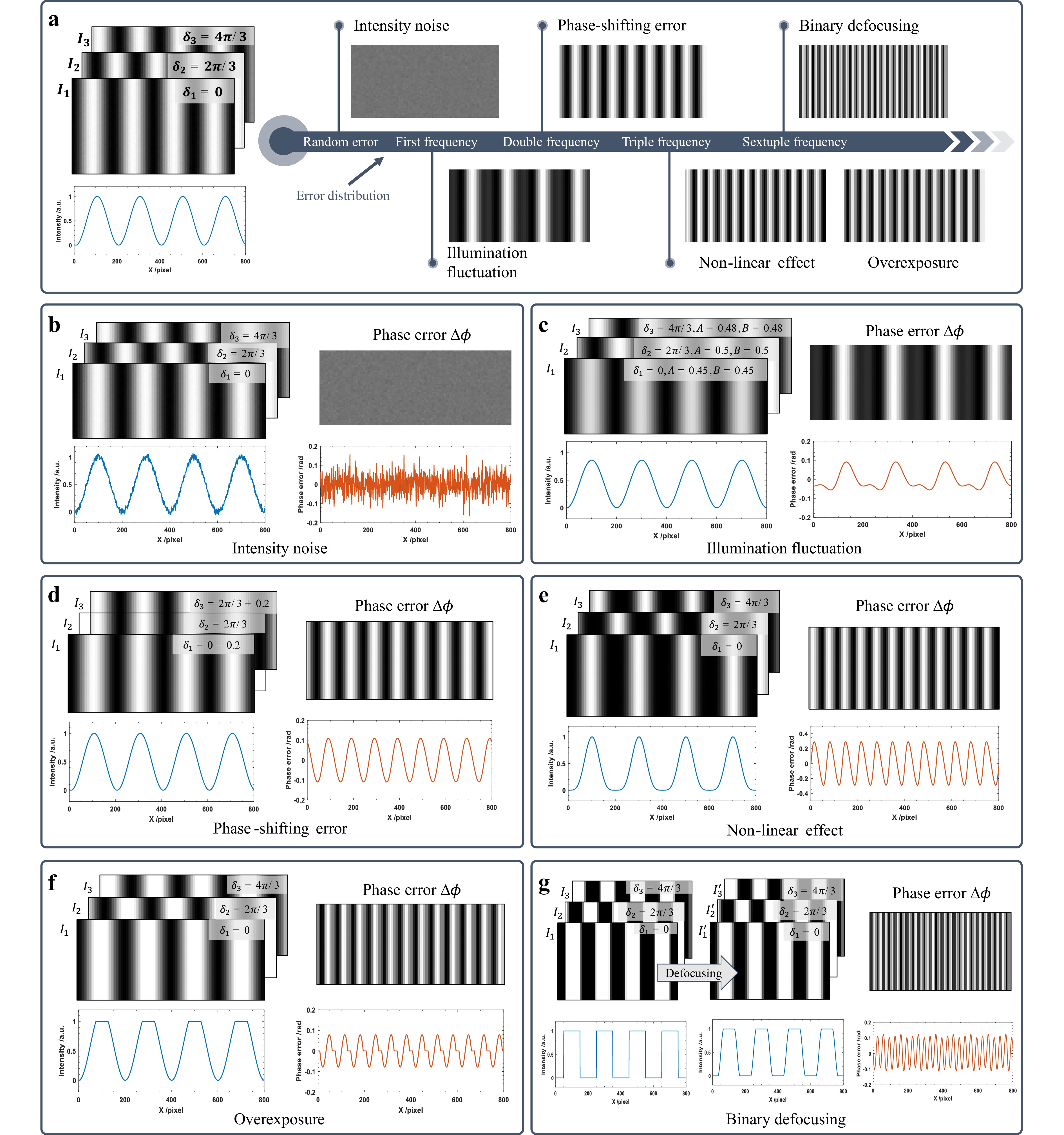
Fig. 8 Phase-shifting fringes and their phase errors affected by different noise sources using 3-step PMP: a Classification of phase error compensation methods. b Intensity noise. c Illumination fluctuation. d Phase-shifting error. e Non-linearity effect. f Overexposure. g Binary defocusing.
-
The standard deviation of the phase error contained in the unwrapped phase obtained using the N-step phase-shifting algorithm can be expressed as253:
$$ {\sigma }_{\phi }=\sqrt{\frac{2}{N}}\frac{{\sigma }_{n}}{Bf} $$ (9) From the above equation, to minimize the impact of intensity noise on the reconstruction results, the most direct methods involve increasing the number of phase-shifting steps N, modulation intensity B, and fringe frequency f. Among these, increasing the number of phase-shifting steps reduces the measurement efficiency and makes the object more susceptible to motion errors during the measurement. Therefore, researchers have focused on improving the other two parameters while reducing the number of projected images. This technical evolution is illustrated in Fig. 9a.

In addition to the direct approach of using the available dynamic range of the projector as much as possible, some studies have optimized the amplitude of the effective components in the projected phase-shifting fringes to increase the modulation intensity80,81. Wang et al.80 related the optimization of N phase-shifting patterns as a point distribution problem in an N-dimensional coding space, achieving the maximum fringe SNR through optimization. Zuo et al.81 leveraged the insensitivity of three-step phase shifting to triple harmonic errors. By altering the triple harmonic components in the sinusoidal fringes, they increased the amplitude of the effective fundamental frequency component, thereby enhancing the dynamic range of the fringes. Another approach involves denoising the fringe patterns. Fu and Zhang254 proposed an image decomposition method to reduce the fringe pattern noise. Fig. 9b, c show the results of these methods.
In terms of increasing the fringe frequency, although a higher fringe frequency can effectively reduce the impact of intensity noise, it also increases the error amplification factor in the temporal phase unwrapping process and reduces the success rate of phase unwrapping. Therefore, the maximum fringe frequency should be determined in conjunction with a specific FPP system and phase-unwrapping strategy.
For more detailed discussions regarding fringe frequency and intensity noise, readers may refer to the works of Zuo et al.44 and Wang et al.84.
-
Although increasing the number of phase-shifting steps or using more stable light sources can reduce the impact of illumination fluctuations, this leads to decreased measurement efficiency or increased hardware costs. The post-processing of images using algorithms is a more efficient approach. Onodera and Ishii85 measured the phase of six interferograms and obtained the phase after error elimination by least-squares fitting of the interference fringes with an interferogram function containing changes in the laser power and intensity. Zhang and Zhang255 used a stable xenon lamp as a substitute for an unstable liquid crystal display/light-emitting diode (LCD/LED) lamp. Liu et al.86 proposed an iterative algorithm that used the least-squares method to calculate the phase shift and wavefront phase in two steps. The fluctuation factor was determined during the phase-shift calculation, and the intensity fluctuations were compensated during the wavefront phase calculation. Lu et al.87 corrected the errors caused by illumination fluctuations using a histogram of the phase map. Chen et al.88 established a mathematical model for the time-varying unstable projection light intensity and based on this, they proposed a method for real-time correction of phase errors due to illumination instability. The results of some of these methods are shown in Fig. 10.
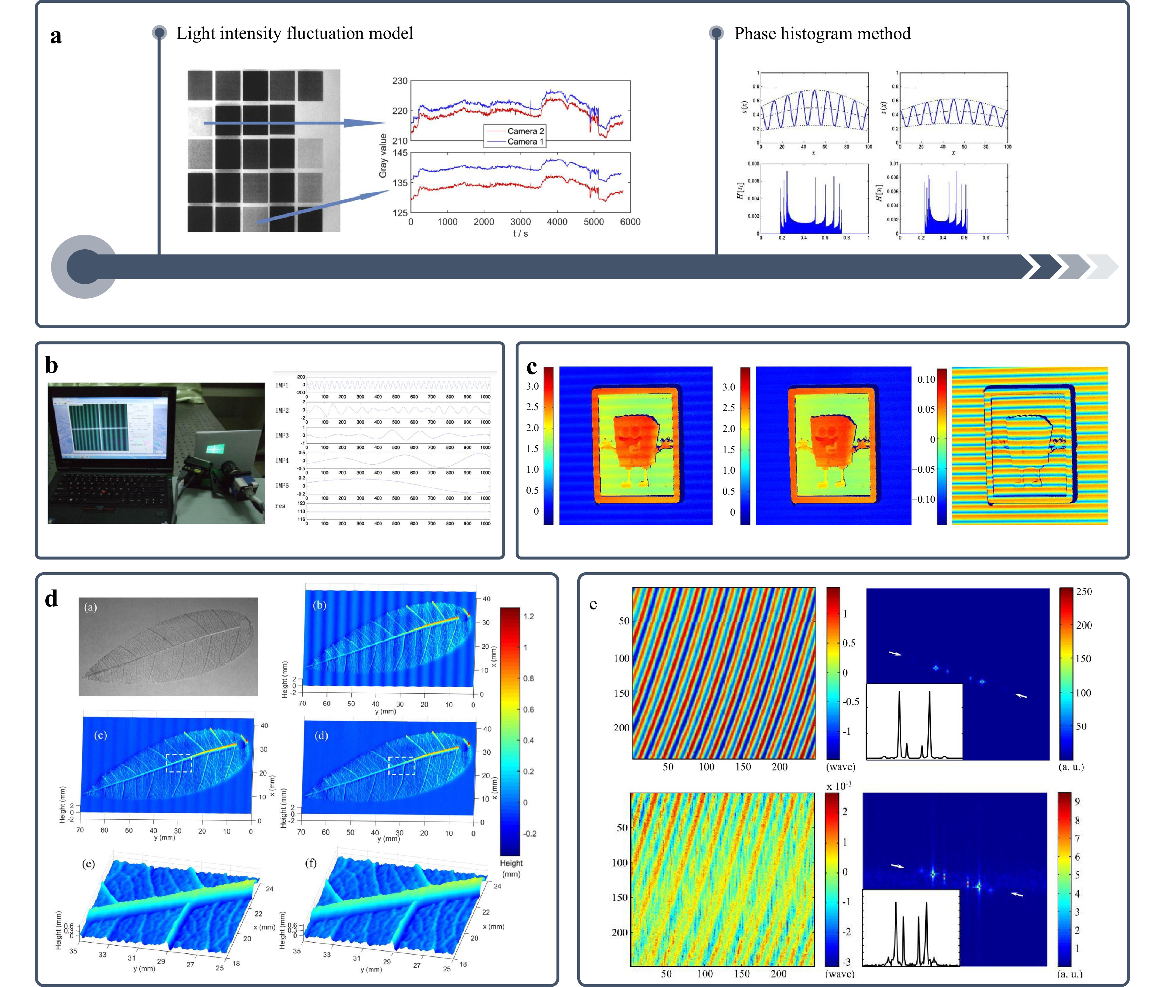
Fig. 10 Results of illumination error correction methods. a Classification of illumination fluctuation error correction methods. b Method based on empirical mode decomposition255. c Method based on histogram of phase87. d Real-time error correction method88. e Iterative-based method86. (Reproduced with permission from Ref. [86]. Copyright 2015, IOP Publishing.)
Similar to other types of errors, correction methods for illumination fluctuation errors are also being developed to achieve higher efficiency and precision. However, the time-varying nature of illumination fluctuation itself makes these methods relatively sensitive to ambient light and object surface reflectivity88. Therefore, the development of more robust algorithms requires further exploration.
-
One of the prerequisites for accurate phase recovery in phase-shifting profilometry is the precise knowledge of the phase shifts, as shown in Fig. 11a. In practice, however, phase-shift errors arise from two primary sources: (1) imperfections in mechanical phase-shifting devices, such as motion delays and non-uniform stepping (Fig. 11b) and (2) the dynamic motion of the measured object. The former can be mitigated using phase-shift-insensitive algorithms90,92,256. This subsection focuses on motion-induced phase errors, which are more challenging because of their spatially and temporally varying nature. When an object moves during acquisition, a single camera pixel integrates light from different physical points over time, causing pixelwise deviations in the effective phase shift.
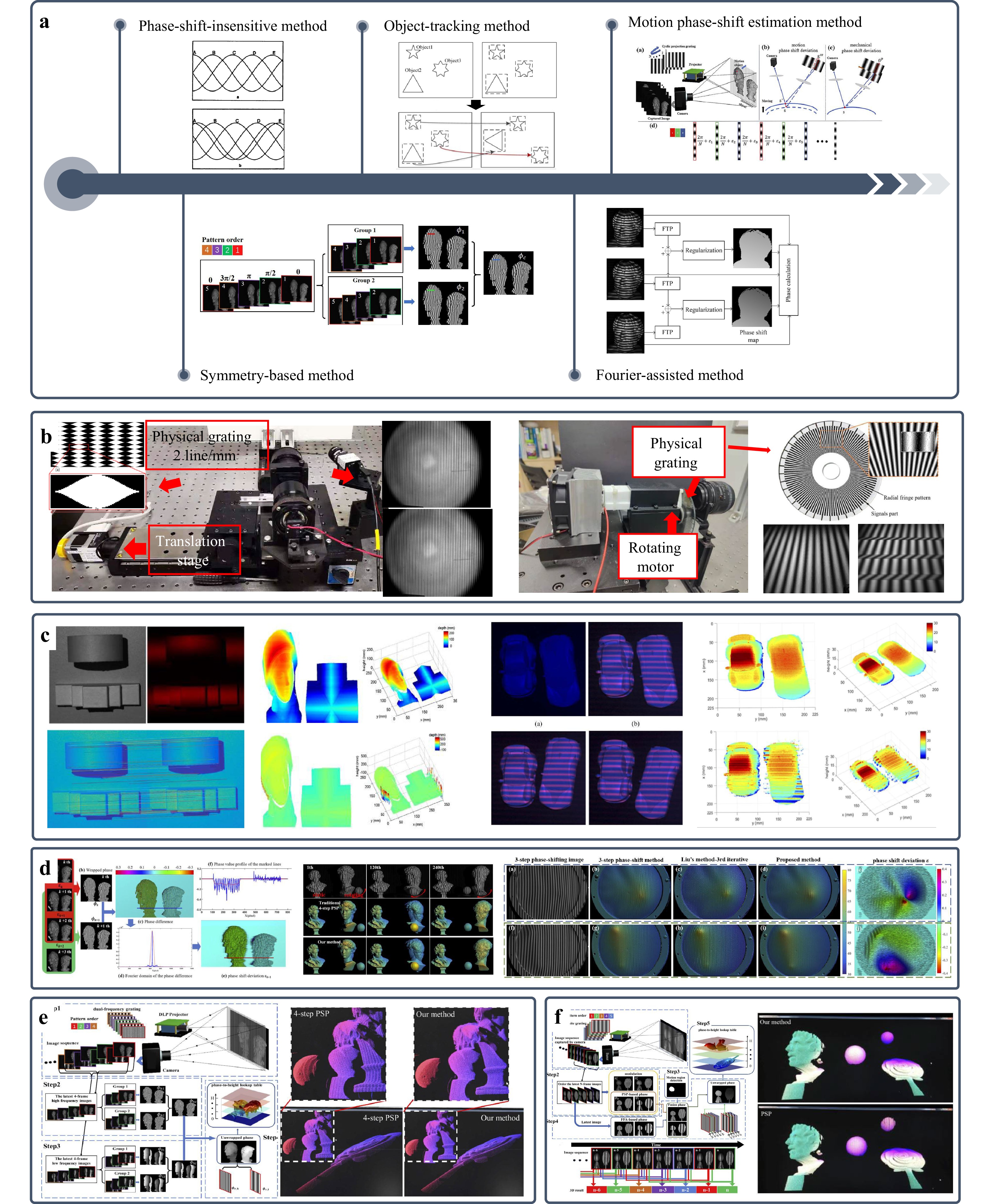
Fig. 11 Phase-shifting error correction methods and their results. a Classification of phase-shifting error correction method. b 3D measurement system based on mechanical phase shifting. c Motion error compensation method based on object tracking95,266. d Motion error compensation method based on phase-shift deviation estimation266. e Symmetry-based motion error compensation method for 4-step PSP268. f FTP-assisted motion error compensation method271. (Reproduced with permission from Ref. [266]. Copyright 2025, IEEE.)
To address motion-induced errors, the existing correction strategies can be broadly categorized into four groups: (i) object-tracking-based methods, (ii) phase-shift deviation estimation methods, (iii) phase-averaging- or symmetry-based methods, and (iv) FTP-assisted methods.
(i) Object-tracking-based methods compensate for motion errors by estimating the 3D trajectory or displacement of the object across frames. Some scholars have studied compensation methods based on motion tracking. Weise et al.91 compensated for motion-induced errors using Taylor expansion to estimate the motion and position offset. Lu et al.95 proposed a method based on Scale-Invariant Feature Transform (SIFT) to compensate for measurement errors caused by rigid body motion, as shown in Fig. 11c. Sui et al.257 proposed a method for extracting codeword maps by considering the motion of projection pixels among the frames. Duan et al.258 proposed a motion-estimated PMP based on a fringe-oriented synthetic phase correlation algorithm to accurately detect the sub-pixel displacements of moving objects according to the object surface features. He et al.259 proposed a bivariate polynomial distribution to describe and correct the phase errors caused by the arbitrary motion of a measured object. Kang et al.260 proposed a dynamic 3D shape measurement method using structured light based on a motion-induced phase shift. Wang et al.261 used digital image correlation technology to track the three-dimensional motion of an object. These approaches effectively reduce the errors under uniform or rigid motion along specific axes. However, their performance degrades significantly under non-uniform, non-rigid, or complex 3D motion scenarios.
(ii) Phase-shift deviation estimation methods directly extract the actual (unknown) phase shifts from the acquired fringe patterns. Feng et al.262 proposed an iterative method for calculating the average phase-shift deviation of a single segmented object. Wang et al.263 successfully reconstructed the 3D shape of uniformly dynamic scenes using a motion-induced error reduction method with additional temporal sampling. Liu et al.264 performed motion error compensation by estimating the object motion from the difference between two 3D shapes. Most of these methods require iterations for accurate motion phase-shift deviations, which increases the complexity of the calculation process. Liu et al.265 proposed a real-time motion error compensation method that estimated the unknown phase-shift deviation for 4-step phase shift fringe patterns. Guo et al.266 proposed a generalized phase-shift deviation estimation method for extracting phase-shift deviations from the difference information between adjacent phases without additional projection fringes, as shown in Fig. 11d. These phase-shift deviation estimation methods can effectively reduce the phase-shift errors of deformed objects through pixelwise error compensation. Although powerful, most of these methods rely on iterative optimization, which increases the computational complexity.
(iii) Phase-averaging- or symmetry-based methods exploit the harmonic characteristics of motion errors, particularly their second-order distribution, to cancel errors through symmetric phase design or post-processing. Wang et al.267 used the Hilbert transform to calculate an additional phase and reduced the motion-induced errors by averaging the original and additional phases. Guo et al.268 realized the reverse distribution of motion phase error by constructing π/2 phase shift of image groups, and proposed a reverse average motion phase error compensation method of 4-step phase shift, as shown in Fig. 11e. Yao et al.269 adjusted the projection sequence of the 4-step phase shift fringe pattern, which further improved the computational efficiency. These phase-averaging methods calculate the average phase map of the regular phase shifted patterns and π/2 phase shifted patterns to cancel out the variability motion-induced errors. Wu et al.270 approximated the phase change as an unknown but linear phase shift and proposed a gradient-based equal-step 3-step phase-shifting algorithm to suppress the motion errors.
(iv) FTP-assisted methods leverage the inherent motion robustness of FTP, which reconstructs phase from a single fringe pattern and thus avoids inter-frame motion errors. FTP requires only a single fringe pattern for phase reconstruction, inherently avoiding errors caused by motion from the source. Therefore, many researchers have combined FTP with PSP for phase error compensation. Cong et al.272 applied FTP to two adjacent frames of phase-shifting fringes to extract the phase separately and then used the difference to estimate the phase-shift error. Li et al.273 performed an FTP transform on a single high-frequency fringe pattern to obtain the object phase and then referenced the phase obtained from a set of low-frequency phase-shifting fringes to generate the final high-precision phase map. Qian et al.274 detected moving regions of the object within the image and then used FTP to compensate for PMP motion error in these regions, while fully retaining the PMP results in stationary regions. As shown in Fig. 11f, Guo et al.271 used a dual-frequency composite grating to acquire high and low-frequency wrapped phases, employed a virtual high-frequency method to identify moving regions in the image, and finally fused the phases obtained from FTP and PMP to achieve real-time motion error elimination.
In summary, although significant progress has been made, most motion error compensation methods impose constraints, such as assuming uniform motion, requiring prior knowledge of object kinematics, or relying on iterative refinement. This limits their applicability to general dynamic scenes. Spectral-based and hybrid approaches offer broader robustness but are constrained by the inherent resolution limits of FTP on complex surfaces. For a more detailed comparison of these phase-shifting error correction methods, readers can refer to the comparative review by Lu et al.96.
-
Non-linear responses in digital projectors introduce high-order harmonic components into the projected fringe patterns, leading to periodic phase errors in PMP. Even though increasing the number of phase-shifting steps can suppress these harmonics275,276, it compromises the measurement speed, rendering such approaches unsuitable for high-speed dynamic applications. Consequently, recent research has focused on achieving an effective non-linear error compensation with a minimal number of fringe patterns. Existing strategies fall into two main categories: pre-compensation methods (which pre-compensate for non-linearity before projection) and post-compensation methods (which correct errors during the post-processing of the captured images), as shown in Fig. 12a105.
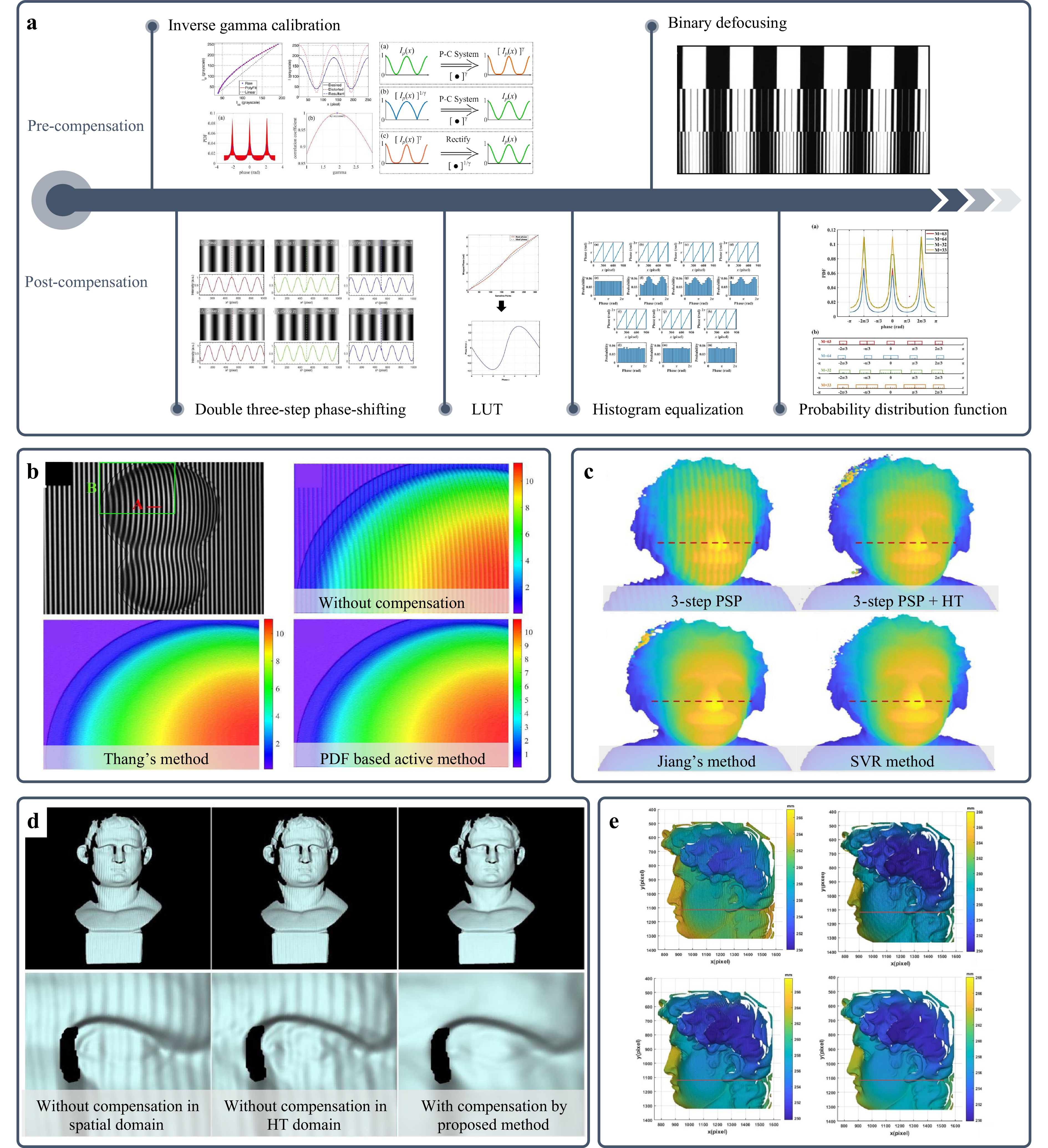
Fig. 12 Non-linear error compensation methods and their results. a Classification of non-linear error compensation methods. b Pre-compensation method based on PDF106. c Pre-compensation method based on SVR277. d Post-compensation method based on Hilbert transform278. e Post-compensation method based on Gauss-Newton iterations279. (Reproduced with permission from Ref. [277]. Copyright 2022, IEEE.)
Pre-compensation methods aim to linearize the output of the projector by pre-distorting the input fringe patterns using an inverse model of the non-linear response of the system. The main idea is to obtain the projector's response function f through calibration and then apply its inverse function f −1 to the original images to ensure the sinusoidal nature of the projected fringes. Huang et al.98 fitted the greyscale response curve of a projector with a polynomial and achieved linear compensation of the greyscale curve by applying the inverse of this polynomial to the projected fringes. Guo et al.99 applied the property that the cumulative distribution function (CDF) of the fringes is independent of the phase and frequency to establish a look-up table from the CDF to the gamma value. Hoang et al.101 calculated an accurate gamma value by solving the non-linear function between the phase from large-step phase-shifting fringes and the actual distorted phase. Liu et al.102 proposed an accurate mathematical model to describe the relationship between phase error and gamma, where the actual gamma value can be estimated from the harmonic coefficients of the phase. Li and Li103 further proposed a strict model for gamma distortion that considered the defocusing effect, making the predicted gamma value more accurate under defocusing conditions. Peng et al.104 employed cubic spline interpolation instead of the traditional single-parameter gamma to better fit the response curve of the projector. Yu et al.106 leveraged the relationship between the probability density function (PDF) curve of the truncated phase and gamma to establish a look-up table through simulation. This method can accurately determine the gamma value using as few as three fringe patterns. The workflow and experimental results are shown in Fig. 12b. Muñoz et al.107 treated the gamma value estimation as a one-dimensional optimization problem that calculates the gamma value by minimizing the difference between the gamma-corrected phase plane and the least-squares plane. Wang et al.108 considered a defocused optical system affected by non-linearity and proposed a method that used two response curves to jointly determine the appropriate precoding gamma value. Cai et al.277 introduced the support vector regression (SVR) concept from machine learning for non-linear correction. They used a dataset containing PDF curves and gamma values to train the SVR model. During measurement, the actual PDF was inputted into the SVR model to estimate the gamma value of the system. The workflow and experimental results are shown in Fig. 12c.
In addition to applying the inverse function of the projector response curve or performing gamma pre-coding, another approach is the binary defocusing technique for fringe patterns. Although binary defocusing inherently avoids the gamma effect of the projector, it introduces defocusing errors and limitations in the measurement depth of field. A detailed introduction and discussion can be found in Section 4.1.6.
Post-compensation methods correct non-linear phase errors after image acquisition without modifying the projected patterns. These can be further grouped based on their underlying principles. Symmetry-based error cancellation: Huang et al.210 designed a dual three-step PMP scheme with a π/3 initial phase offset, yielding two phase maps with opposite first- and third-order errors, and averaging them cancelled non-linear distortions. Similarly, Cai et al.278 observed that applying the Hilbert transform to distorted fringes produced a phase-error distribution opposite to that of the original, enabling compensation via phase averaging, as shown in Fig. 12d. Look-up table (LUT) approaches: Zhang and Yau280 proposed a general LUT method applicable to arbitrary phase-shifting steps, constructed by measuring phase errors on a flat reference surface. Pan et al.100 used the property that the period of the non-linear phase error is the same as that of the phase-shifting steps and proposed an iterative phase error compensation method. Yu et al.106 and Liu et al.281 linked the PDF of the wrapped phase to the harmonic error coefficients, enabling error reconstruction from phase statistics. Wang et al.282 proposed a phase-shifting histogram equalization method for non-linear correction and used spline interpolation to eliminate discretization errors caused by histogram equalization. Song and Kong279 projected an additional mask image alongside dual-frequency fringes, used least squares to estimate high-order harmonics, and recovered the true phase via Gauss-Newton iterations, as shown in Fig. 12e.
Compared with pre-compensation methods, post-compensation methods generally involve more complex computational processes and have limited application scenarios. When the object is at a different position or the projector's focus is altered, passive methods often fail to effectively suppress the phase errors caused by non-linearity105. Passive methods offer better robustness when the non-linear response of a system changes over time283. In other cases, active methods are more accurate and efficient.
-
Current research on high dynamic range (HDR) problems can be divided into two main categories: device-based and algorithm-based methods. Device-based methods reduce the impact of high reflectivity on the measurement results by modulating the camera's exposure time, the projector's intensity, or by adding other equipment, as shown in Fig. 13a.
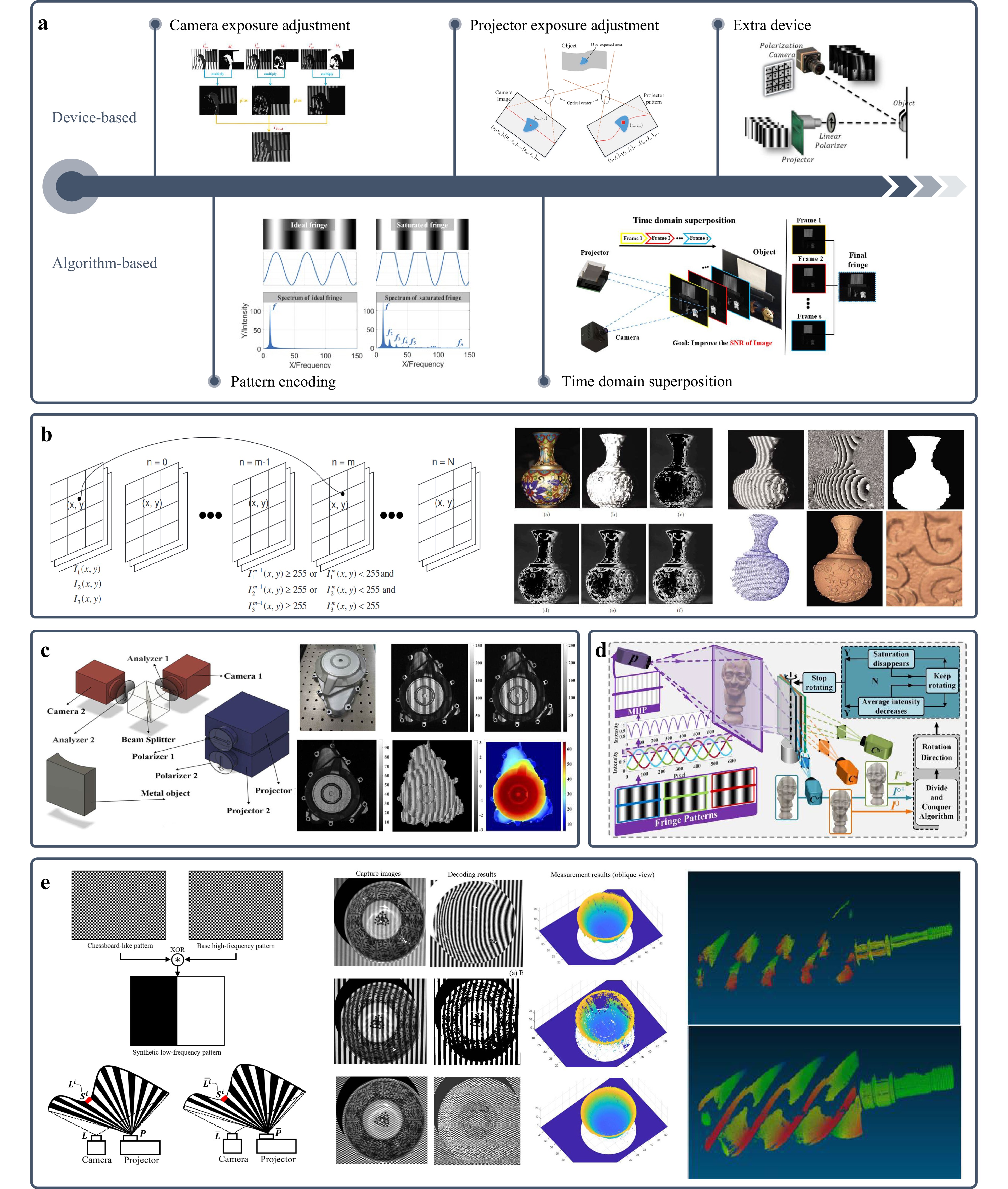
Fig. 13 HDR measurement methods and their results. a Classification of HDR error correction methods. b Multi-exposure method110. c HDR measurement using polarization device116. d HDR measurement using scanning mirror devices284. e HDR measurement based on pattern encoding285. (Reproduced with permission from Ref. [110]. Copyright 2009, SPIE. Reproduced with permission from [285]. Copyright 2021, IEEE. Reproduced with permission from [284]. Copyright 2023, IEEE.)
Zhang and Yau110 proposed a multiple exposure technique in which pixels from multiple fringe patterns captured at different exposure times were selected. The pixel with the maximum intensity value (which was not saturated) was selected from the corresponding pixels in each set, and the results were fused into a single fringe pattern. The algorithmic workflow and experimental results are shown in Fig. 13b. The selection of exposure times for this method relies on subjective experience, and the multiple exposure process is time-consuming. Therefore, many researchers have proposed methods to automatically select exposure times and reduce the number of exposures. Jiang et al.112 used the degree of modulation as a criterion for selecting pixels from the original fringe patterns, thereby automatically obtaining fringes with a high SNR. Ekstrand and Zhang111 estimated the global optimal exposure time by analyzing the surface reflectivity of the object. Feng et al.113 further divided the histogram distribution of the measured surface reflectivity into several groups and adaptively predicted suitable exposure times for each group. Rao and Da115 automatically calculated the exposure time by analyzing the degree of modulation and maximum fringe intensity of each pixel, enabling the measurement of HDR regions with a maximum of five exposures. Zhang286 pre-calibrated the camera's response function to objects of different reflectivity, determined the intrinsic constant parameters of the camera response, and ultimately determined the optimal exposure time through a single exposure.
In addition to adjusting the exposure time to prevent camera saturation in HDR regions, the required images can be acquired by varying the projected light intensity. Waddington and Kofman287,288 linearly adjusted the maximum input grey level (MIGL) of the projector and fused phase-shifting fringes captured under different MIGLs into a single set of images. Li and Kofman289 locally modified the MIGL of the projected fringes based on saturated pixels in the captured images, requiring only three sets of fringes to complete the HDR measurement. Sheng et al.290 corrected the projected image based on feedback from the overexposed pixel information, reducing the intensity of the projector pixels corresponding to the overexposed points.
Furthermore, introducing additional hardware into the system can also assist in the 3D measurement of HDR scenes, such as using polarization devices109,113,116,291 (Fig. 13c), scanning mirror devices284 (Fig. 13d), or photometric stereo techniques292–294.
Algorithm-based HDR techniques do not require repeatedly adjusting the device parameters or introducing additional hardware but improving the fringes or phase at the algorithmic level to enhance the measurement accuracy. Chen and Zhang114 found that when fringe periods were odd and even numbers respectively, a specific number of phase-shifting steps allowed accurate phase recovery from the overexposed fringes. Jiang et al.295 projected an additional set of inverted fringes and partially or wholly replaced the original fringes based on the overexposure conditions to compensate for the phase errors. Qi et al.296 investigated the influence of the number of phase-shifting steps and degree of overexposure on the phase error and discussed the selection of optimal system parameters. As shown in Fig. 13e, He et al.285 designed a chequerboard-patterned fringe to suppress the local high reflectivity and used the intersection information of the chequerboard for decoding. Tan et al.297 applied an idea based on the Hilbert transform to phase calculations from overexposed fringes.
Overall, among the hardware-based methods, multiple exposure techniques and methods used to adjust the projection intensity exhibit high accuracy. Their lack of additional hardware makes them easy to integrate into existing FPP systems. However, they require a relatively large number of fringe patterns, resulting in a low measurement efficiency, which makes them difficult to apply to online measurements. Incorporating additional hardware can, in principle, avoid high-reflection areas, but it also introduces drawbacks such as reduced SNR and increased system complexity. Algorithm-based methods can effectively reduce the required number of fringe patterns. However, approaches that increase the number of phase-shifted fringes or alter the image encoding can also reduce the measurement efficiency to some extent. Further reviews and comparisons can be found in other survey articles298,299.
-
Although binary defocusing technology offers advantages, such as high speed and immunity to non-linear effects, it also leads to reduced fringe contrast, decreased measurement depth of field, and higher-order harmonic errors. Currently, the compensation techniques for binary defocusing phase errors can be classified into two categories: intensity-based and phase-based optimization methods, as shown in Fig. 14.
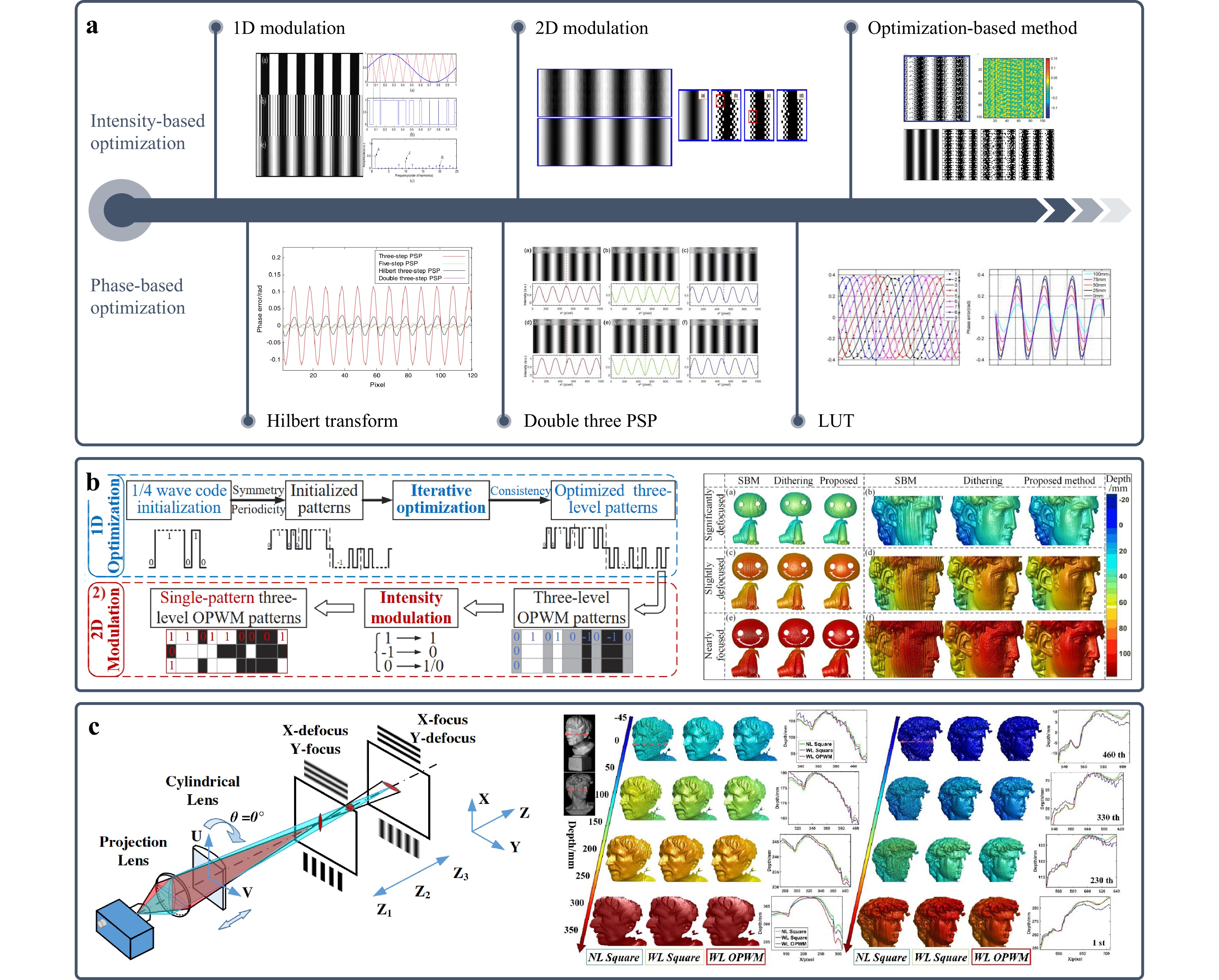
Intensity-based optimization methods aim to generate fringes with good sinusoidal quality after applying the low-pass filtering effect of the projector by altering the intensity distribution of the projecting binary fringe patterns. Early research introduced pulse width modulation (PWM) techniques117 into binary defocusing to eliminate higher-order harmonics in binary square waves, such as sinusoidal pulse width modulation (SPWM)118,121 and optimal pulse width modulation (OPWM)119. However, owing to the inherent characteristics of one-dimensional modulation, these methods cannot be effectively applied to cases with large fringe periods or when the projector is near focus. To address these issues, researchers have proposed fringe optimization methods based on two-dimensional modulation techniques. Some of these methods use dithering techniques from digital printing to improve the fringe quality. Wang and Zhang120 applied Bayer dithering to fringe images to generate high-quality wide-period fringes. Lohry and Zhang302 combined the Floyd-Steinberg error diffusion algorithm with a genetic algorithm to determine the most suitable diffusion kernel matrix for defocusing. You et al.303 theoretically analyzed and compensated for the inherent bias present in the FS error diffusion. Although dithering techniques can quickly eliminate higher-order harmonics, their accuracy is limited by the dithering technology itself and requires further improvement.
Another approach is to minimize the intensity error or phase error between the target binary fringe and ideal fringe. Dai and Zhang122 and Dai et al.304 optimized a dithered binary fringe by changing the greyscale value (0 or 1) of each pixel individually. To further improve the optimization speed and measurement accuracy under different defocusing conditions, researchers have replaced pixel-by-pixel optimization with block-by-pixel optimization. By combining different objective functions and optimization strategies123,124,305-307, binary defocusing schemes with a broader application scope were proposed. However, the optimization process for two-dimensional modulation is typically very time-consuming, and its efficiency is low when dealing with different fringe periods and defocusing levels. As shown in Fig. 14b, Zhu et al.300 obtained an optimal 1D intensity distribution through a 3-grey-level OPWM optimization strategy and then extended it along another dimension using a binary modulation strategy. This method achieved rapid optimization of binary fringes for large fringe periods and varying defocusing levels. As shown in Fig. 14c, Zhu et al.301 placed a cylindrical lens in front of a projection device, and set its tilt angle to approximately 45°. The anisotropic filtering effect of the cylindrical lens effectively eliminated the higher-order harmonic components in the binary fringes while simultaneously increasing the measurement depth of field without altering the structure of the FPP system. In addition, Kamagara et al.308 and Wang et al.309 conducted quantitative analyses and discussed how to select an appropriate defocusing level.
Phase-based optimization methods use the characteristics of the phase distribution for error compensation. Zhang310 found through analysis that the errors in the three-step phase-shifting binary defocusing fringes primarily originate from the 6th and 12th harmonic components. Therefore, additional 3-step phase-shifting fringes with phase shifts of π/6 and π/12 were introduced to eliminate the errors at these frequencies. Zheng et al.311 applied a Hilbert transform to the 3-step phase-shifting binary fringes and averaged the results with the original phase, thereby eliminating the 5th harmonic error. Wang et al.312 merged dual 3-step phase-shifting fringe patterns into a single image with three greyscale levels, binarized it using two-dimensional area modulation, and further suppressed errors using a Hilbert transform. Xu et al.313, Liu et al.314, and Zhang et al.315 established look-up tables that mapped the absolute phase or phase error to depth, enabling the recovery of object depth information by looking up the corresponding values.
Regardless whether the methods are intensity-based or phase-based, the goal of these methods is to overcome the limitations of traditional binary defocusing techniques with the aim of increasing the measurement depth of field and improving the measurement accuracy. However, their application scenarios differ, and they should be selected based on practical requirements. When binary defocusing fringes must be obtained quickly without increasing the number of projected patterns, 1D modulation techniques and dithering-based 2D modulation techniques can be used. When only the accuracy of the phase after defocusing is considered, more time-consuming optimization-based 2D modulation techniques or look-up table methods requiring prior system calibration can be employed. Additional optical element methods can be used to achieve defocusing measurements with a large depth of field. A more detailed discussion of one-dimensional and two-dimensional modulation techniques can be found in the review article by Li et al.316.
In this section, the technical routes and research progress of phase error compensation techniques are reviewed from six aspects: intensity noise suppression, illumination fluctuation error correction, phase-shifting error correction, non-linear error compensation, high dynamic range measurement, and binary defocusing error compensation. Overall, phase error compensation is regarded as one of the most critical components in fringe-projection-based structured light 3D measurement technology. Researchers have conducted extensive research focusing on measurement accuracy, speed, and robustness. The research methods are complex and diverse, with varying degrees of integration in different fields such as optics, 1D signal processing, 2D image processing, and probability statistics, leading to significant technological developments.
-
In high-speed dynamic 3D measurements, even with extremely fast acquisition, inevitable differences exist between consecutive frames, leading to motion-induced artefacts. From a theoretical perspective, single-frame fringe projection methods are therefore most suitable for capturing dynamic scenes. Among these, FTP stands out because of its computational efficiency and ease of parameter selection and has become the most widely used approach in high-speed 3D shape measurements. As illustrated in Fig. 15a, the principle of FTP-based dynamic measurement technique involves projecting a high-frequency fringe generated by a physical grating via Köhler illumination onto the object surface. The recorded fringe sequences can be analyzed frame by frame using a two-dimensional Fourier transform or directly processed in three dimensions to obtain a wrapped 3D phase field. After 3D phase unwrapping317 to ensure continuity in all directions and system calibration, the true 3D geometry of the scene can be reconstructed.
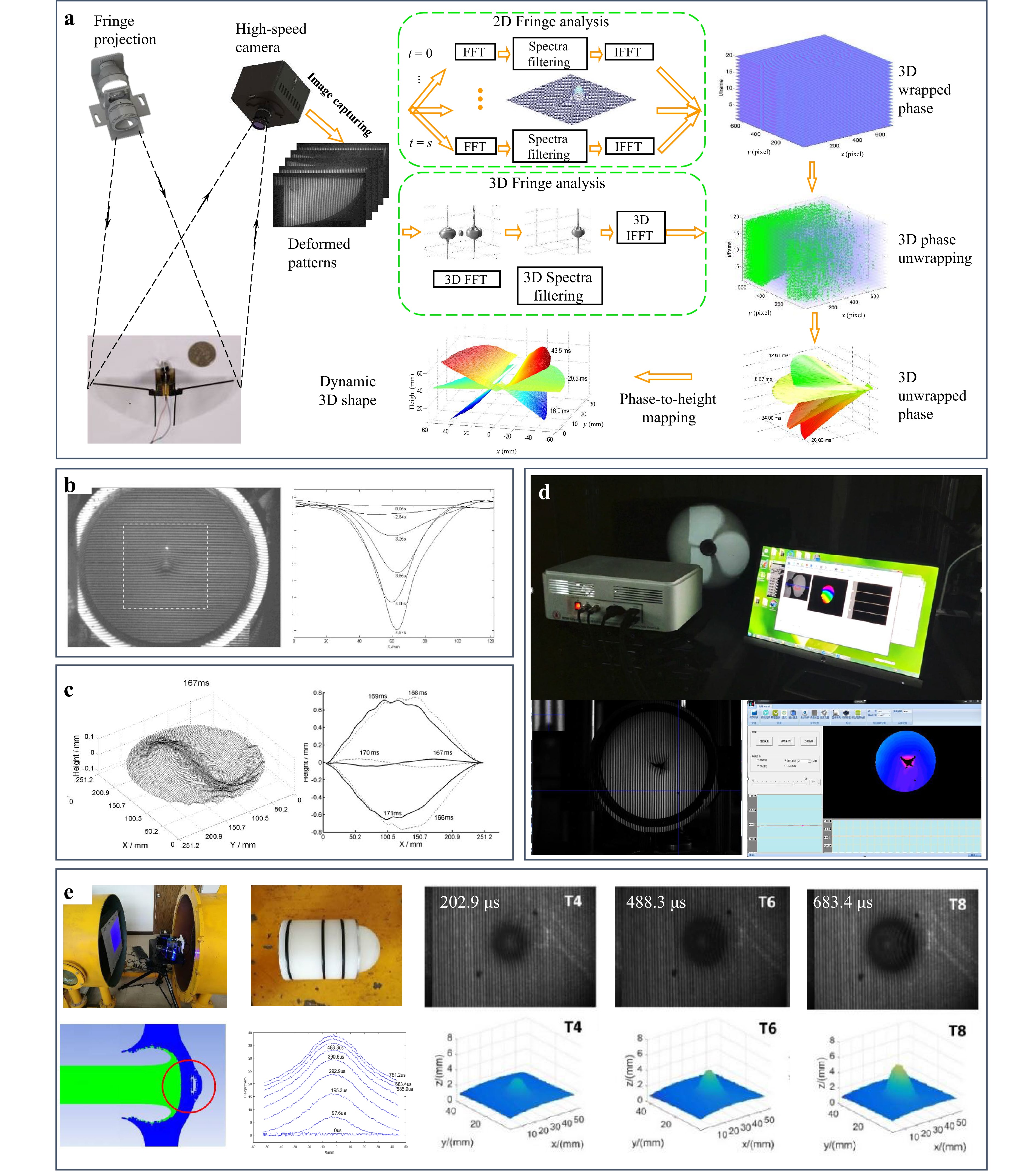
Fig. 15 Principles and developments of FTP for high-speed dynamic 3D measurements. a Basic principle of FTP using physical grating projection and Fourier analysis317. b, c Early extensions for dynamic liquid vortex measurement and eardrum vibration capture318,319. d Further optimization including stroboscopic illumination, high-frequency vibration reconstruction, and flapping-wing microaerial vehicle measurements320. e Advanced application to hypervelocity impact experiments for aerospace research. (Reproduced with permission from [318]. Copyright 2002, Elsevier.)
To the best of our knowledge, Zhang and Su first introduced FTP to dynamic measurements in 2002 and successfully captured the evolution of the liquid vortex formation318, as shown in Fig. 15b. Subsequently, this technique was used to measure eardrum vibrations319, as shown in Fig. 15c. A key advantage of FTP is that it does not require pattern switching, enabling the use of a simple physical grating as both the projection and illumination source. This avoids the cost and complexity of DLP projectors and mechanical phase-shifting devices. Building on this principle, Zhang et al. further employed stroboscopic illumination to measure high-speed rotating fan blades320, as shown in Fig. 15d, and later recorded the rapid shape changes of flapping-wing microaerial vehicles317 and cracks on the impacted membrane surface. Subsequently, using the same system, Zhang et al. measured the 3D shape of target surfaces under hypervelocity impact at speeds of several kilometres per second, providing accurate 3D data for spacecraft protective structural design and detonation/penetration analysis, as illustrated in Fig. 15e. These pioneering studies firmly established FTP as a cornerstone technique for dynamic 3D shape measurements, demonstrating its effectiveness and scalability for capturing highly transient processes.
Traditional FTP relies on spatial-domain filtering, which inevitably leads to the loss of high-frequency details. To address this limitation and enable dynamic measurement of objects with abrupt changes, Qican321, Zhang et al.322, and Liu et al.323 proposed temporal Fourier transform profilometry (TFTP). This method records the fringe sequences of the dynamic process and performs a pixel-by-pixel temporal Fourier transform to reconstruct the evolving 3D shape pointwise. Because TFTP analyses signals in the temporal domain rather than in the spatial domain, it eliminates the need for high-frequency fringes. Instead, it requires synchronization between the fringe switching and camera acquisition to satisfy the sampling theorem. Zhang et al. implemented a rotating grating to generate rapid phase-shifting patterns and prove this conception, as shown in Fig. 16a.
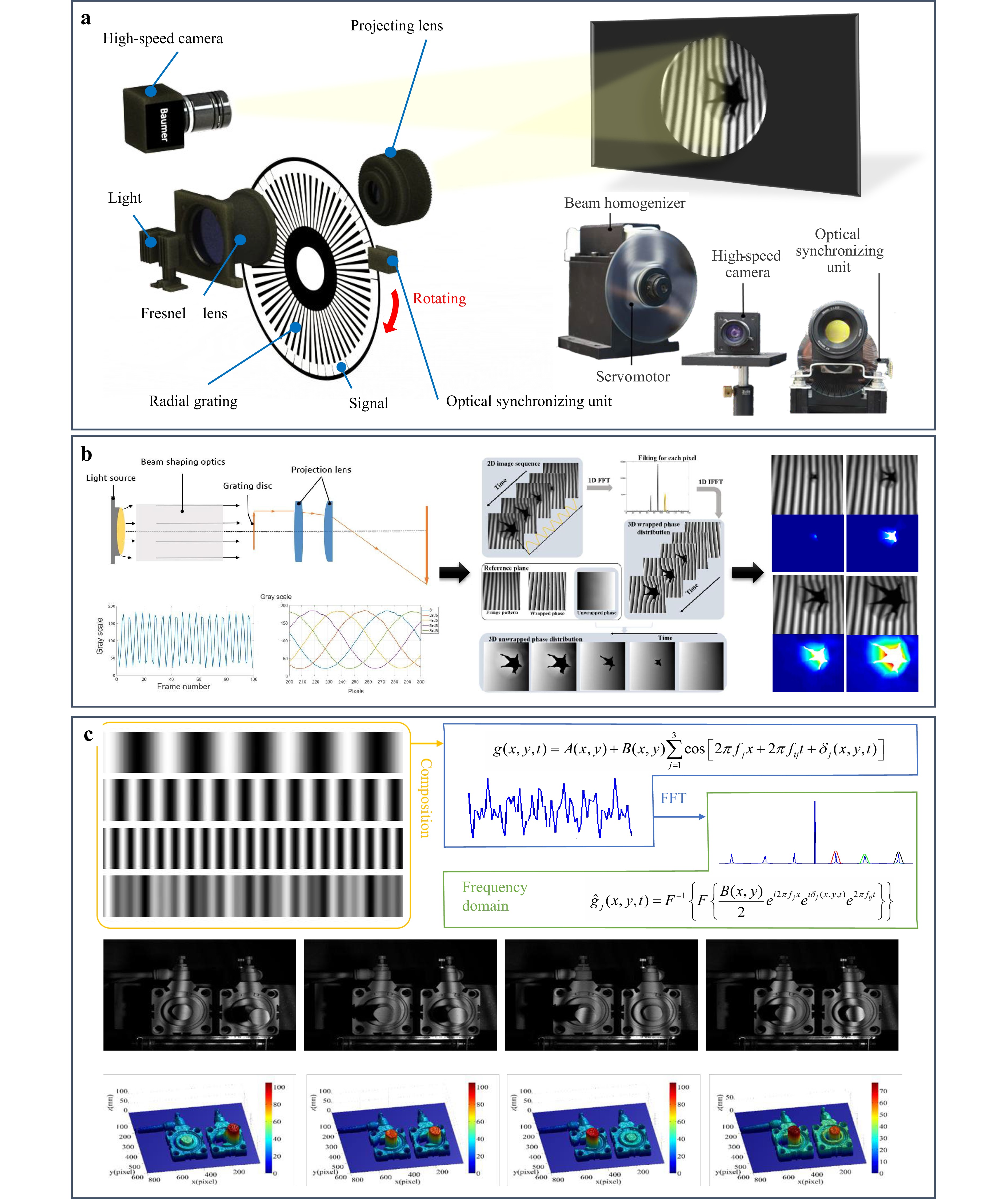
The key idea of TFTP is to transfer the height-encoded modulation from the 2D spatial frequency domain in the FTP to the 1D temporal frequency domain for each pixel. Consequently, the spatial continuity assumption in FTP is replaced by the temporal continuity requirement in TFTP. In practical dynamic measurements, discontinuities and abrupt depth variations in space are common; however, it is easier to guarantee temporal continuity at a fixed spatial point. This fundamental shift makes the TFTP particularly suitable for capturing discontinuous and rapidly changing surfaces.
In practice, TFTP requires at least one 2D spatial phase map to be unwrapped at a certain moment during the dynamic process, which serves as the initial reference for temporal phase unwrapping across all pixels. To relax this requirement, Liu et al. introduced a reference-plane-assisted 3D phase unwrapping approach323, in which the calibrated phase of a reference plane guided the initial phase unwrapping of the measured object. This enabled the reconstruction of dynamic events such as impacts and fractures, as shown in Fig. 16b. However, this strategy still imposes constraints on a limited depth range. To completely eliminate the dependency on a spatially unwrappable initial frame, Zhang et al. proposed a temporal three-frequency composite TFTP method324. In this approach, three different frequency fringes were sequentially projected to produce composite temporal signals. By applying temporal filtering, the signals were separated into three wrapped phases, which were then jointly unwrapped using multi-frequency temporal phase unwrapping to obtain an absolute and continuous phase distribution, as shown in Fig. 16c. This innovation enabled the successful 3D reconstruction of complex dynamic processes, such as the reciprocating motion of a cylinder push rod, while preserving fine spatial details and handling cases in which no single spatial frame could be reliably unwrapped.
To fundamentally address the phase unwrapping challenges of FTP in isolated or randomly varying dynamic scenes and achieve a universal absolute phase reconstruction strategy, Zuo et al. proposed micro Fourier transform profilometry (μFTP)325. In this method, three high-frequency fringe patterns with slightly shifted frequencies were sequentially projected in a cyclic manner. A white image was inserted between two consecutive fringes, and the camera synchronously recorded the high-speed sequence, as shown in Fig. 17a. The captured data were first processed using background-normalized FTP to obtain high-quality wrapped phases. Next, three sets of wrapped phases were combined and unwrapped through a novel temporal phase unwrapping with projection distance minimization (TPU with PDM) algorithm. Compared with conventional multi-frequency unwrapping strategies, μFTP achieved a significantly larger measurable depth range and stronger robustness against noise, without relying on a spatially continuous reference plane.
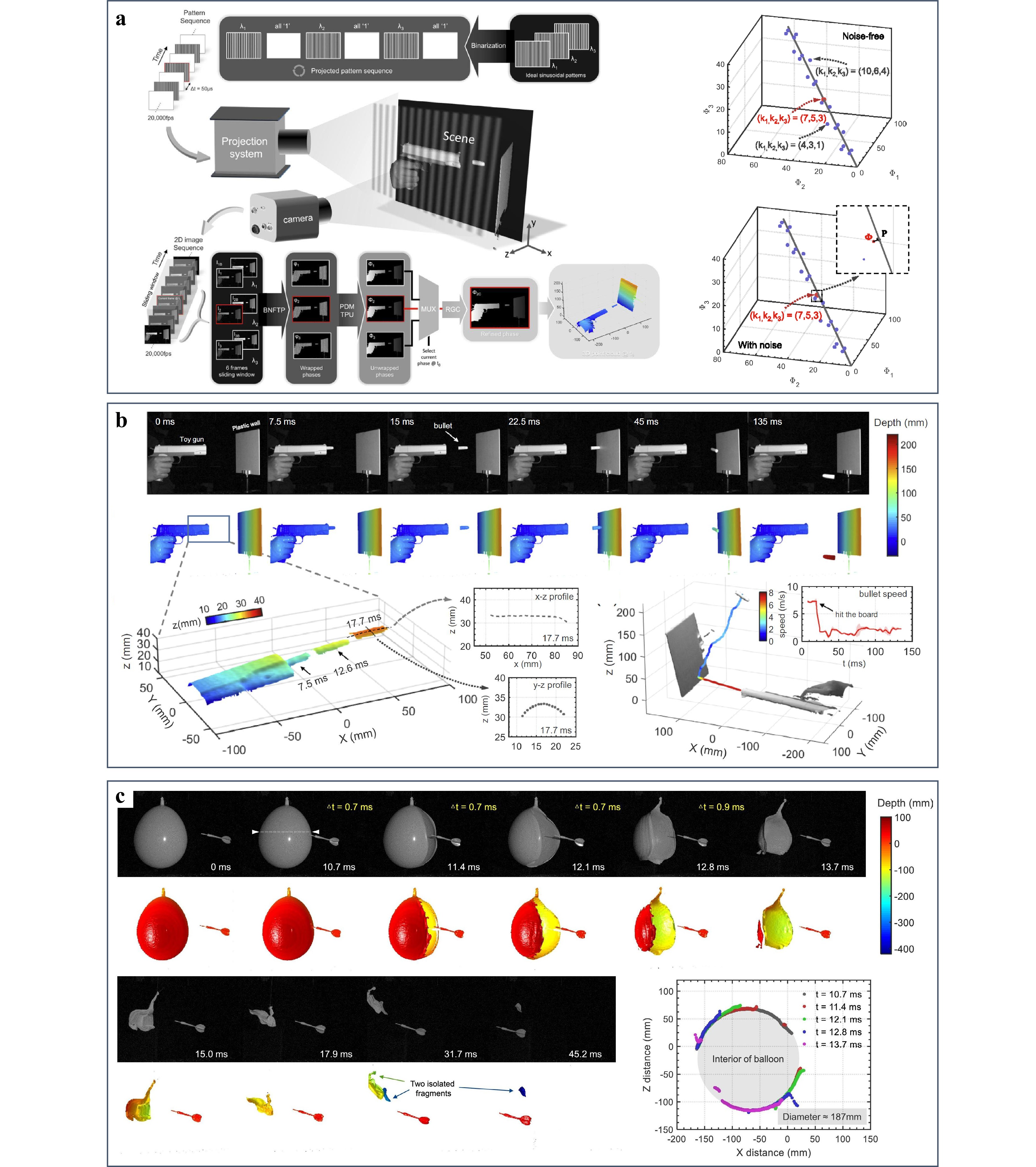
Benefiting from this design, the authors demonstrated 3D reconstructions of highly transient events such as bullet ejection and balloon rupture at frame rates of up to 10,000 fps, as shown in Fig. 17b, c. These results showed that μFTP not only preserved the high-speed advantages of the FTP family but also overcame the limitations of TFTP in handling discontinuous or complex dynamic scenes, thus providing a more general and reliable solution for absolute measurements in ultrafast 3D imaging.
-
Compared with transform-domain single-frame methods, multi-frame PMP43,242,326,327 has found broader applications in optical metrology. In this approach, a sequence of phase-shifting fringe patterns is projected onto the object surface, and the phase of each pixel is calculated independently along the temporal axis. Because the PMP relies on point-to-point computations rather than additional filtering operations, it offers higher measurement accuracy, better flexibility, and stronger robustness against abrupt reflectivity variations or surface discontinuities.
To extend the PMP to dynamic measurement scenarios, researchers have advanced the field from both algorithmic and hardware perspectives. On the algorithmic side, the central objective is to reduce the number of projected patterns while ensuring a reliable absolute phase reconstruction, as shown in Fig. 18a. The classical two-frequency phase-shifting method requires two sets of three-step phase-shifting fringes (3 + 3) for absolute phase unwrapping. To further decrease the number of projected patterns, Zuo et al. proposed a bi-frequency number-theoretical method53, exploiting the invariance of the fringe average during two-frequency fringe projection. By directly computing the average from high-frequency fringes and combining it with the π-shifting algorithm, only two low-frequency patterns were needed. This reduced the total number to five (3 + 2). Subsequently, Zuo et al. presented a four-pattern strategy (2 + 2)131, and two slope intensity patterns with opposite directions were summed to construct the mean and subtracted to generate a unit-frequency phase. With two π-shifting fringes, absolute phase reconstruction can be achieved with only four patterns.
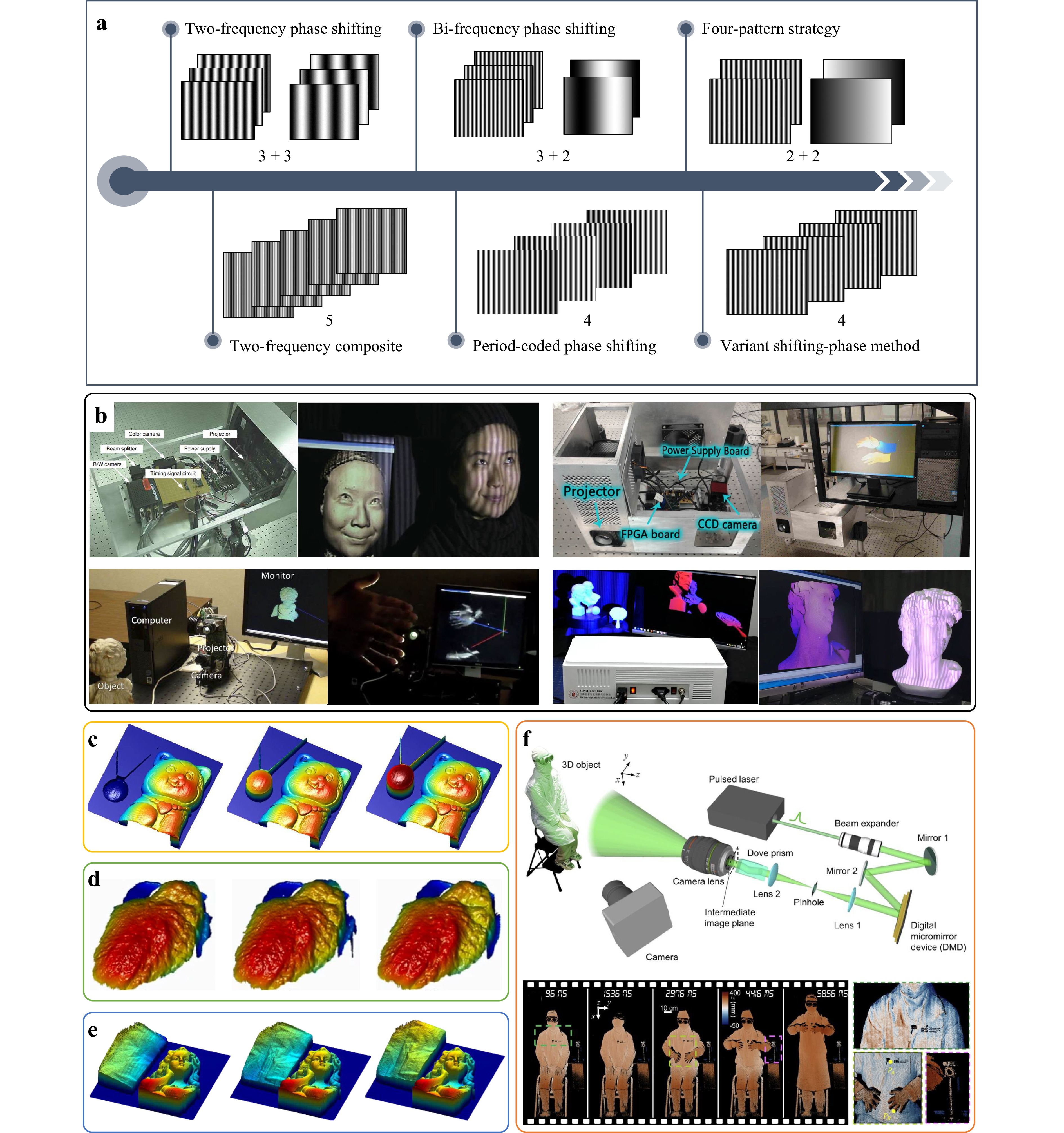
Fig. 18 Development of PMP for dynamic 3D measurements. a Algorithmic development of PMP for dynamic measurements, focusing on reducing projected patterns and adopting fringe-composite strategies. b Hardware progress with DLP projectors, GPU acceleration, and binary defocusing for real-time measurements. c-f Representative results, showing higher speed, efficiency, and larger measurement ranges in dynamic 3D reconstruction51,53,330,331. (Reproduced with permission from [53]. Copyright 2013, Elsevier Ltd.)
Although these methods effectively reduce the number of projected patterns, they are still based on sequential two-frequency modulation. Therefore, they are not ideal for frame-by-frame updating. To address this limitation, researchers have proposed fringe-composite strategies based on cyclic projection so that each newly added pattern can immediately update the reconstruction and achieve an equivalent single-frame performance. Following this idea, Liu et al. developed a new two-frequency composite scheme128, which embedded two frequencies into one pattern and separated them using different phase-shift steps, thereby reducing the required number of patterns from six to five. Subsequently, Wang et al. proposed a period-coded phase-shifting strategy328, embedding auxiliary periodic signals into standard four-step fringes to resolve phase ambiguities. These signals were carefully designed to occupy the "free space" of the patterns, maximizing the SNR while enabling dual-frequency absolute phase reconstruction with only four patterns. More recently, Wu et al. introduced a two-wavelength, four-pattern phase-shifting method329 that leveraged a variant-shifting phase strategy to simultaneously reconstruct two-phase maps at different wavelengths.
On the hardware side, the widespread adoption of DLP projectors and the acceleration enabled by GPU-based parallel computation have paved the way for real-time dynamic measurements using phase-shifting techniques. By combining efficient algorithms with hardware optimization, researchers have realized highly accurate real-time 3D measurement systems, as illustrated in Fig. 18b.
In 2009, the emergence of binary defocusing techniques have enabled the rapid switching of phase-shifting fringe patterns125,313,316,332, which in turn shifted research interest towards high-speed, high-accuracy 3D shape measurements based on pointwise phase-shifting methods. By introducing temporal phase unwrapping to dynamic 3D measurements, researchers have established direct mapping between phase and height along the temporal axis, thereby allowing pixelwise unwrapping of wrapped phases in complex or isolated static scenes.
In the multi-frequency category, additional phase-shifting fringes at different frequencies are projected to resolve the phase ambiguities. Fig. 18 illustrates three representative two-frequency unwrapping techniques: two-frequency, number-theoretical, and two-wavelength methods. Based on these algorithms, Wang and Zhang employed a three-frequency heterodyne approach to project binary fringes at 5,000 Hz and achieved 3D reconstructions at 556 Hz using nine patterns per result51, as shown in Fig. 18c. To improve efficiency, Wang et al. later adopted a two-frequency strategy requiring only six patterns and successfully reconstructed the surface dynamics of a beating ex vivo rabbit heart330, as shown in Fig. 18d. Building on this, Zuo et al. further optimized the efficiency by proposing a bi-frequency number-theoretical method, reducing the projection sequence to only five patterns and enabling 3D reconstruction at 1,250 fps53, as shown in Fig. 18e. More recently, Jiang et al. introduced a band-limited projection system that replaced conventional DLP projectors with a 4f spectrum-filtering design to generate high-quality sinusoidal fringes. Compared with binary defocusing, this system achieved a deeper effective measurement depth and enabled metre-scale measurement fields. Using this system, they captured human body motion over a large field of view331, as shown in Fig. 18f.
To achieve robust measurements under high-noise conditions, researchers have introduced Gray codes to assist the phase-shifting techniques for phase unwrapping. The Gray code, first proposed by Gray at Bell Labs in the 1940s333, is designed such that any two adjacent codewords differ by only one bit (i.e. a Hamming distance of 1). Since the maximum and minimum codes also differ by only one bit, they are often referred to as cyclic or reflected codes. The Gray code offers strong robustness and noise immunity as a reliable encoding scheme that minimises errors. However, when applied to dynamic measurements, it suffers from jump errors and a low coding efficiency.
Two methods have been developed to address the jump errors: post-correction and pre-avoidance strategies. Post-correction methods directly unwrap the phase using erroneous wrapped phases and decoded orders, and then exploit the continuity and monotonicity constraints of the unwrapped phase to detect and correct errors via median filtering334, monotonicity detection335–337, or principal component analysis338,339. Although these methods can correct both order jump errors and noise-induced errors, they are less effective in dynamic scenes where object motion and projector defocusing broaden the errors. Therefore, post-correction methods are more suitable for static scenes. Pre-avoidance strategies aim to eliminate jump errors in advance. Representative approaches include complementary Gray code62 and tripartite phase unwrapping58, where interleaved wrapped phases and fringe orders are constructed to avoid jump errors. On this premise, many studies have been conducted to improve the robustness of phase unwrapping340–350.
In addition to error correction, the low coding efficiency remains another limitation of Gray-code-assisted phase shifting, hindering its application in dynamic measurements. To encode N fringe periods, at least log2N Gray code patterns are required. This implies that 16 periods typically require three phase-shifting fringes and four Gray code patterns. To improve efficiency, researchers have focused on expanding coding capacity and enhancing code utilization. For capacity expansion, Zheng et al.229 proposed a ternary Gray code by applying binary quantization to generate an additional "0.5" level through defocusing, and it effectively increased the number of encodable fringe orders from 2ᴹ to 3ᴹ for M Gray code patterns. Inspired by this, He et al.230 further extended the method to quaternary Gray codes, achieving higher efficiency at the cost of a reduced SNR, making it suitable primarily for low-noise environments.
To avoid SNR degradation, Wu et al. extensively explored utilization-enhancing strategies. First, they proposed the cyclic complementary Gray code61 and shifting Gray code59, both capable of avoiding order jump errors without requiring additional patterns, and achieved a 310-fps 3D reconstruction. Following this, they proposed a time-overlapping Gray code, in which each Gray code pattern was reused multiple times across phase-shift sequences, significantly improving the efficiency to 452 fps. Finally, he further extended this idea to time-overlapping structured light projection, which enabled the absolute labelling of 32-period fringes with only three projected patterns, achieving a 3,174-fps reconstruction of complex, high-noise dynamic scenes, as shown in Fig. 19a. Using these approaches, measurement scenarios such as Newton's cradle impacts, block collapses, fan blade rotations, falling snow, and water balloon bursts were reconstructed, as shown in Fig. 19b-f.
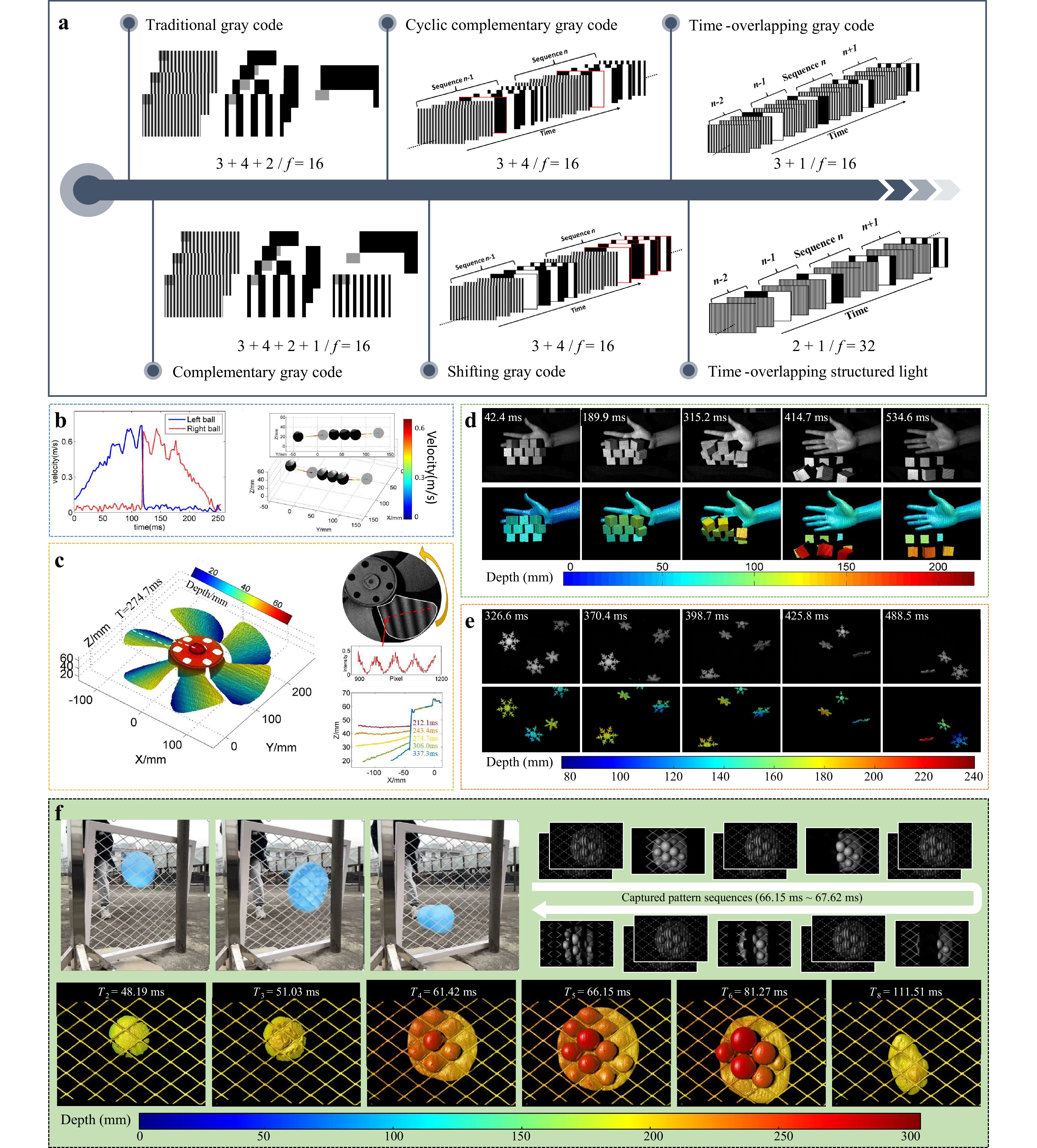
Fig. 19 Development of Gray-code-assisted phase shifting for dynamic 3D measurements. a Evolution of coding strategies to improve efficiency and robustness. b-f Representative dynamic reconstructions such as Newton's cradle impacts, block collapses, fan blade rotation, falling snow, and water balloon bursts58–61.
Through this line of research, the two main limitations of Gray-code-assisted phase shifting are systematically solved, while preserving its superior noise robustness. Compared with dual-frequency phase-shifting methods, Gray-code-assisted phase shifting demonstrates stronger noise immunity and reliability, making it more suitable for high-speed measurements in complex, noisy environments, where the success rate is the priority.
-
Intensity-based 3D imaging has driven the development of miniaturized high-speed projection technologies to address the inherent limitations of conventional digital light processing (DLP) projectors. This line of research traces back to speckle-structured light projections in the virtual reality/augmented reality (VR/AR) consumer electronics industry, in which 3D reconstruction can be achieved by projecting only a single fixed speckle-like or dot pattern. Based on this principle, the Israeli company PrimeSense launched its first 3D sensor in 2006351, as shown in Fig. 20a. The device projected infrared speckle patterns onto a target scene using a vertical cavity surface-emitting laser (VCSEL)352. The depth-modulated image was captured using a camera and subsequently converted into a depth map through spatial correlation, as illustrated in Fig. 20b.
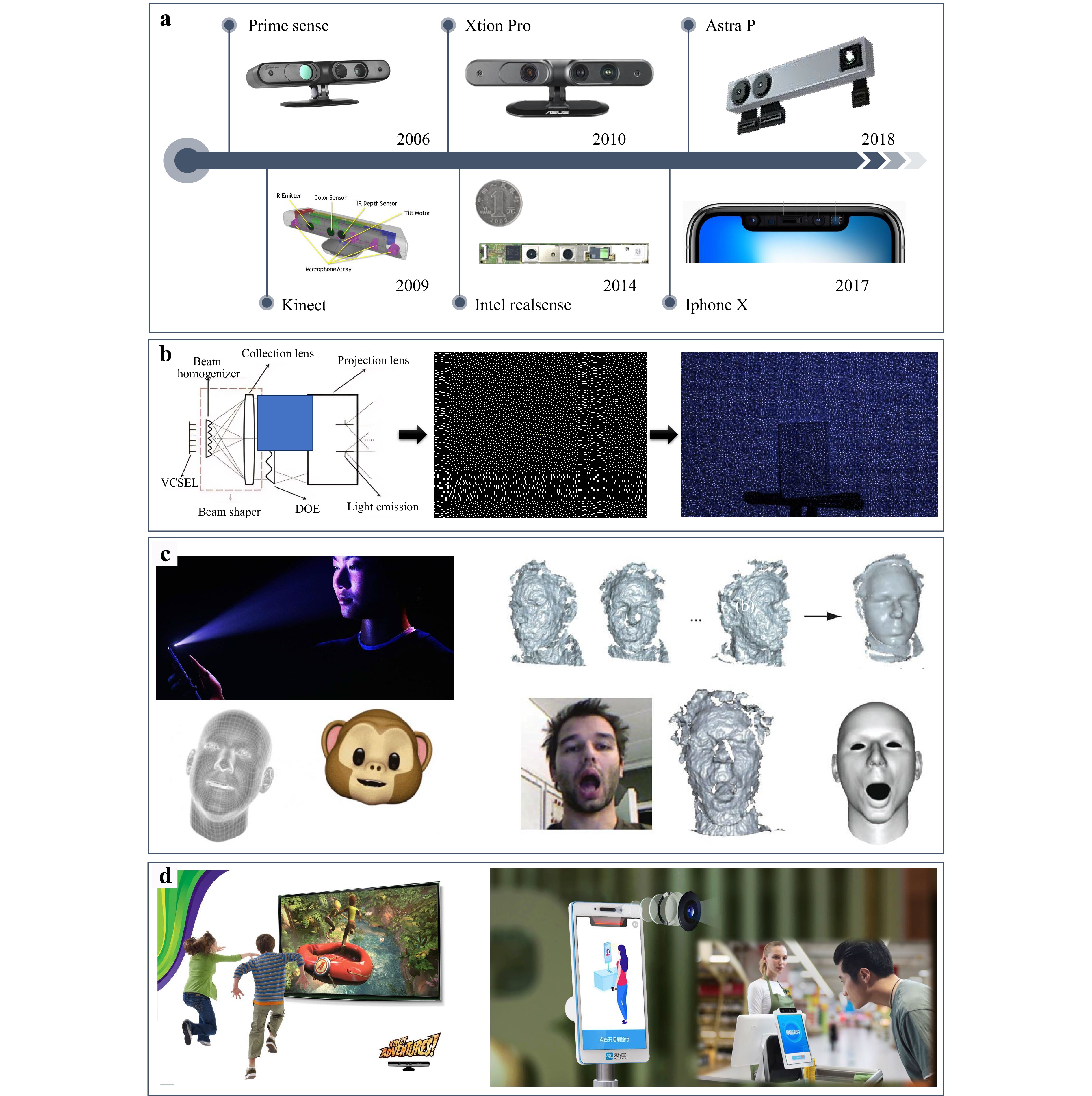
Fig. 20 Origin of speckle structured light projection for intensity-based 3D imaging. a Timeline of representative devices to illustrate the early evolution of the technology. b Principle of depth sensing via infrared speckle projection and spatial correlation. c, d Typical applications including facial recognition, interactive gaming, and mobile payment.
In 2009, Microsoft collaborated with PrimeSense to release the groundbreaking Kinect353, which was a motion-sensing device equipped with a depth camera. Once launched, it became a consumer success and pushed the wave of touchless motion-sensing gaming. Following this, Lenovo and Intel introduced their own products, namely, Xtion Pro354 in 2010 and RealSense355 in 2014, respectively. Compared with earlier devices, RealSense achieved substantial miniaturization and it enabled integration into the front-facing camera modules of laptops. These early systems primarily targeted gaming applications and Apple was the first to push this technology to the public. In 2017, Apple released the iPhone X and it replaced fingerprint-based authentication with 3D facial sensing. After acquiring PrimeSense, Apple successfully miniaturized and embedded the 3D camera into the "notch" display. The Face ID356 supports facial recognition for unlocking and securing mobile payment. In parallel, the Chinese company Orbbec achieved mass production of 3D sensors as early as 2015357, breaking the monopoly of Apple, Microsoft, and Intel. In 2018, Orbbec released the Astra P, a compact 3D sensor designed for smartphone integration.
All of these products were designed for the consumer market. They support tasks such as facial expression tracking, face recognition, interactive gaming, and mobile payment, as shown in Fig. 20c, d. However, to reduce the sensor cost and device size, they adopted speckle structured-light projection with spatial matching, which imposes significant limitations on the measurement accuracy and spatial resolution. For example, Orbbec's Astra P achieved a depth accuracy of 1 mm at a working distance of 600 mm27. Although this level of accuracy is sufficient for daily interactive applications, it is inadequate for high-precision measurements. Moreover, for certain complex and rapidly changing dynamic scenarios (e.g. high-speed impacts, structural collapses, or rotating blades), the measurement capabilities of such systems are limited. Astra P, for example, supports a maximum reconstruction frame rate of 320 × 200 pixels at 60 fps358. In addition, they are insufficient for capturing and quantifying the entire transient process of high-speed dynamic events.
To enhance the accuracy and speed of intensity-based 3D imaging, Schaffer et al. introduced a temporally coded structured illumination technique in 2011 using acousto-optically deflected laser speckles359. By using temporal correlation rather than spatial correlation, this method enabled high-quality pixel-to-pixel measurements. However, the reliance on coherent laser speckles inevitably introduced speckle noise, which degraded the method's robustness and limited its measurement accuracy. To overcome these shortcomings, Heist et al. developed incoherent-light-based alternatives. For example, they proposed an array-LED projector139 and a GOBO projector140. Fast switching and mechanical rotational speeds enable the generation of aperiodic sinusoidal fringe patterns at projection rates of up to 100 and 250 kHz, respectively. Unlike laser-generated speckles, these aperiodic sinusoidal patterns are inherently free of speckle noise. In addition, they have a strong tolerance to optical defocusing and system distortion owing to their sinusoidal distributions. Therefore, these approaches significantly improve the robustness and ensure reliable high-speed 3D measurements, even under unstable experimental conditions.
This intensity-based approach offers additional advantages when combined with a binocular system. It does not require prior knowledge of the projected patterns, and therefore, it can greatly loosen the constraints on the temporal variation of patterns and synchronization between the projection and imaging systems. Moreover, because phase shifting is unnecessary, this approach is especially suitable for ultra-high-speed 3D measurements without sacrificing spatial resolution. Another important advantage of these projections is their spectral flexibility. By simply replacing the illumination source and camera, the same optical set-up can be adapted for measurements across different spectral bands142,143,360-362. This extends the applicability of the technique to multi-spectral or wavelength-selective multi-modal imaging.
The overall development roadmap for the high-speed intensity-based projection is illustrated in Fig. 21a. The projection optical layouts of the two main approaches are shown in Fig. 21b139. Both concepts exploit either the rapid switching of array-LED light sources or the high-speed rotation of a rotating grating/slide disc to generate dynamic projection patterns. By doing so, they easily surpass the inherent projection speed limitations of conventional DLP projectors (approximately 22 kHz). The principle of the aperiodic sinusoidal fringe projection strategy is illustrated in Fig. 21c141. By generating a sequence of non-periodic, phase-shifting fringe patterns, each pixel obtains a temporally unique intensity signal for encoding. The correspondence problem between the stereo images is then resolved by computing the normalized cross-correlation between the temporal intensity sequence of each pixel from the first camera and the intensity variations of the candidate pixels along the epipolar line of the second camera. This temporal correlation strategy enables pixelwise matching with high precision and robustness.
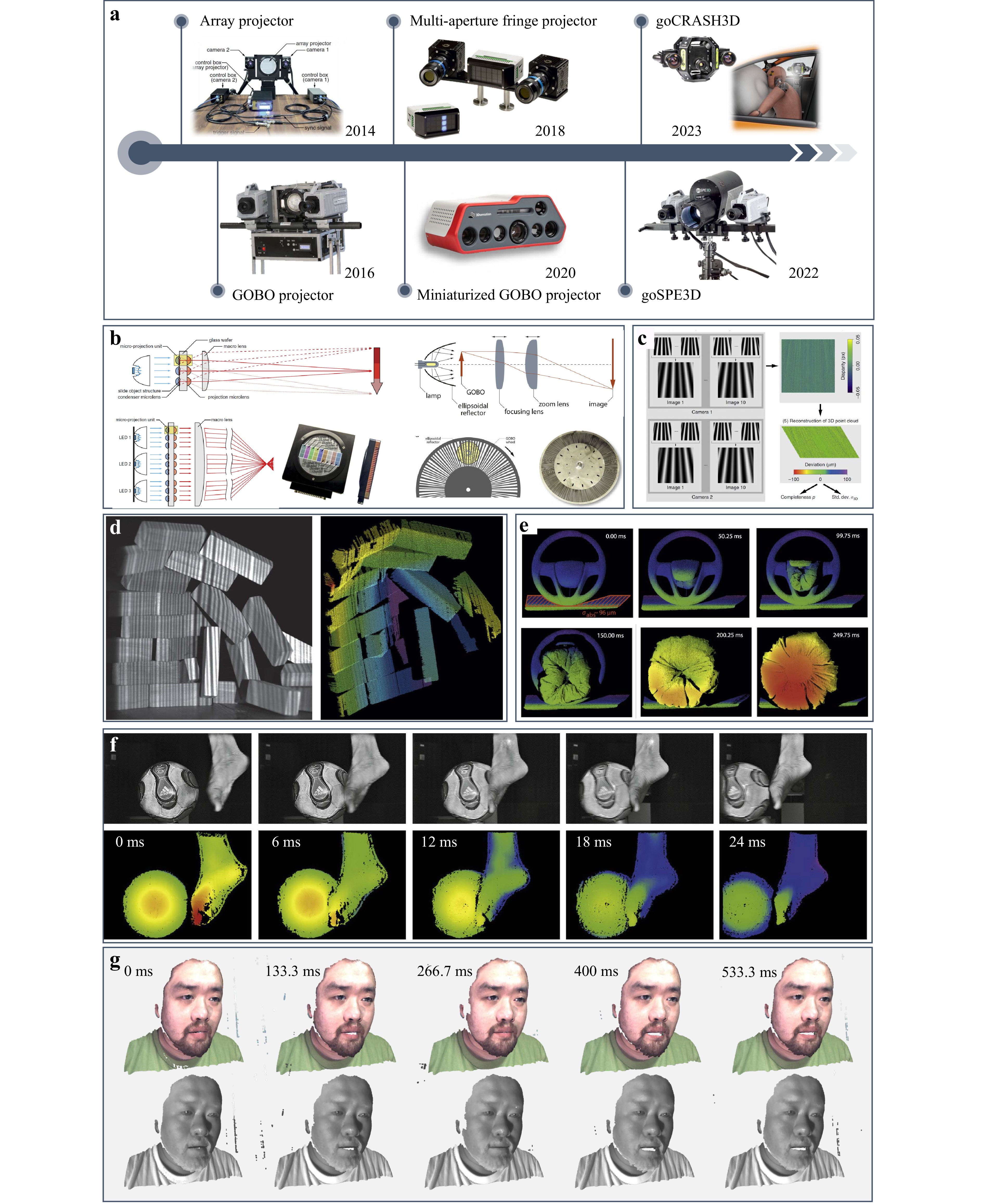
Fig. 21 Advances and evolution of intensity-based 3D imaging technique. a Development roadmap of algorithmic and hardware improvements. b Projection optical layouts of array-LED and GOBO systems139. c Principle of aperiodic sinusoidal fringe projection for pixelwise temporal correlation141. d-f High-speed 3D measurement of dynamic events139,140. g Multi-modal applications such as real-time 3D facial reconstruction for vital sign estimation364. (Reproduced with permission from [139]. Copyright 2014, SPIE. Reproduced with permission from [140]. Copyright 2016, Elsevier Ltd.)
For array-LED projections, Heist et al. first demonstrated a temporal matching method using a proof-of-concept prototype in 2014139. Building on this foundation, they introduced a multi-aperture projection architecture in 2018141 that improved the illumination efficiency and reduced the system volume. Most recently, in 2023, the team released the goCRASH3D system, which was capable of millisecond-range LED clocking, enabling ultra-robust 3D measurements under extreme onboard conditions, such as crash tests. For GOBO-based projections, the group developed a prototype in 2016 that employed a rotating-slide mechanism to project high-speed switching aperiodic sinusoidal patterns. They achieved reconstruction rates exceeding 1,300 fps140, and the optical layout is shown in Fig. 21b. Based on this concept, a compact GOBO projector was developed in 2020, aimed at real-time multimodal measurements. In 2022363, the goSPE3D system was introduced to address ultra-high-speed dynamic measurement tasks at frequencies up to 50 kHz.
Based on these technological advancements, a range of breakthrough applications can be achieved. For instance, transient events, such as collapsing blocks, airbag deployment, and ball kicking have been successfully measured, as shown in Fig. 21d-f. Real-time 3D facial reconstruction and multi-modal measurements for vital sign estimation were also achieved, as illustrated in Fig. 21g.
In summary, the booming phase represented rapid development in the evolution of FPP and was characterized by breakthroughs in measurement accuracy, computational efficiency, and measurement speed. These developments have expanded its utility across industrial inspection, scientific exploration, and biomedical imaging, and paved the way for the next phase of intelligent innovations in computational 3D imaging.
-
In the first two phases, FPP underwent continuous evolution and development for measurement in numerous practical scenarios. Some of these technical advances have already been translated into industrial products and their maturity and wide applicability have been demonstrated. Faced with such progress, some researchers in the field suggested that "the party is over" for FPP and they have even shifted their focus. However, despite the remarkable achievements and extensive applications accumulated over decades of development, several "hard-bone problems" remain unsolved. Moreover, new challenges continue to emerge as measurement scenarios become increasingly complex and diverse. This perspective often reflects a greater sense of resignation when confronted with these persistent difficulties rather than exhaustion of innovation itself. Although many simpler challenges in FPP appear to have been solved (sometimes even overstudied), several significant challenges remain. These include the compatibility of measurement accuracy and efficiency, measurement under complex reflection conditions, such as HDR surfaces, (semi-)transparent objects, inter-reflections, and sub-surface scattering, and measurement under complex transmission conditions, such as robust imaging under strong light interference and scattering media.
The fundamental limitation is that nearly all existing methods are tied to physics-based triangulation models. The contradictions between the single-shot and multi-frame methods make it impossible for traditional methods to achieve both high accuracy and efficiency. In addition, the intrinsic point-to-point phase analysis framework disenables accurate 3D reconstruction under complex illumination conditions.
To achieve genuine breakthroughs, it is necessary to update conventional architectures. In recent years, the rapid advancement of AI and CI technologies has pushed FPP into a transformation phase. Based on these two advanced techniques, AI-based 3D imaging and CI-based 3D imaging have emerged as new alternatives. These studies introduced entirely new frameworks and provided fresh opportunities and transformative potential for FPP. In the following sections, we review the recent progress along these two directions.
-
With the rapid progress of AI, deep learning has emerged as a transformative force for 3D imaging. Unlike traditional coded-projection strategies and physics-constrained phase unwrapping, data-driven approaches learn and map from large amounts of experimental data directly. Instead, they leverage large-scale training datasets and powerful neural architectures. This end-to-end paradigm fundamentally overturns the conventional divide-and-conquer and locally optimized pipelines of classical algorithms365,366. Consequently, deep learning has opened new avenues for fringe analysis, phase unwrapping, and 3D reconstruction. In addition, deep leaning creates a revolutionary shift from rule-based methods to adaptive data-driven intelligence. To date, deep learning has demonstrated superior robustness against noise, efficiency in fringe coding, and strong adaptability to complex scenes, positioning it as the starting point of the transformative phase in optical 3D measurements. Next, we review the progress of AI-driven 3D measurement technologies from four perspectives: AI-based fringe processing, AI-based fringe analysis, end-to-end learning, and physics-informed learning, as shown in Fig. 22a.
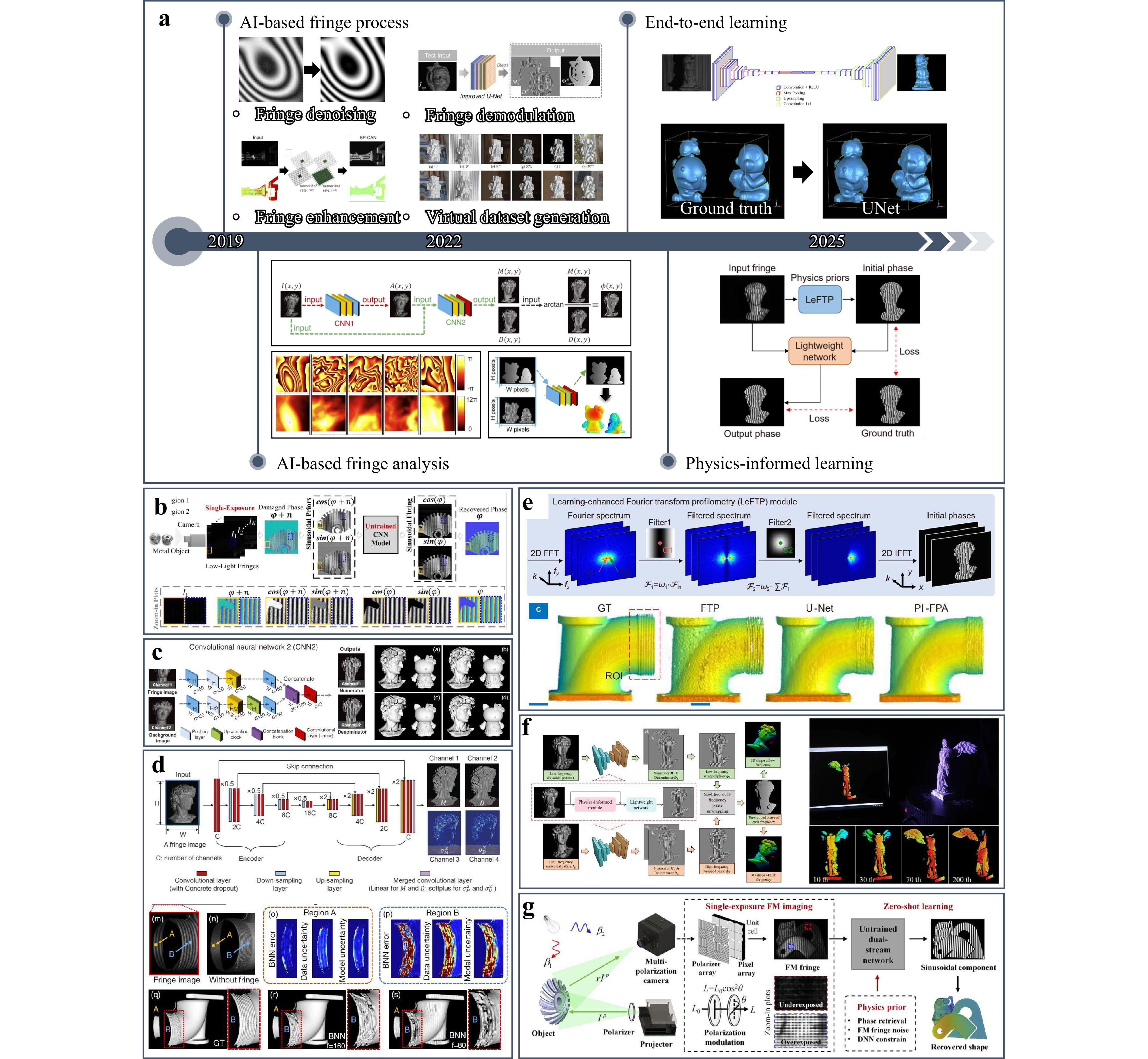
Fig. 22 AI-based 3D imaging. a Progress of AI-driven 3D measurement technologies from four perspectives82,169,173,177,365,366. (Reproduced with permission from [82]. Copyright 2019, Elsevier B.V.) b Deep sinusoidal prior (DSP) for phase recovery from degraded fringes368. (Reproduced with permission from [368]. Copyright 2023, IEEE.) c Deep-learning-based single-frame fringe analysis method169. d Bayesian CNN with uncertainty maps376. e PI-FPA173. f Lightweight PE-Net with spatial-spectral consistency378. g Physics-informed zero-shot learning approach combined with full-resolution multi-polarization (FM) hardware modulation379. (Reproduced with permission from [379]. Copyright 2026, Wiley-VCH GmbH.)
AI-based fringe processing. AI technologies originated from computer vision, where deep learning was widely applied to tasks such as denoising, enhancement, and image restoration. Inspired by this, early attempts in FPP regarded fringe patterns as a special type of structured image and directly transferred AI-based methods from computer vision to fringe processing. The typical tasks include fringe denoising, enhancement, demodulation, and generation for virtual datasets. For fringe denoising, to the best of our knowledge, Yan et al.82 first introduced deep learning, demonstrating that learning-based methods provided better stability, faster computation, and parameter-free operation compared with traditional algorithms. Following this work, researchers developed a series of approaches that targeted specific noise sources and measurement scenarios173. For fringe enhancement, Liu et al.367 proposed a skip pyramid context aggregation network (SP-CAN) to enhance single-exposure fringe images, thereby enabling accurate 3D measurements on highly reflective surfaces. Zhang et al.368 presented a deep sinusoidal prior model for recovering reliable phase information from severely degraded data, as illustrated in Fig. 22b. For fringe demodulation, Li et al.179 applied deep networks to demodulate spatial frequency composite fringes and achieved high-quality absolute surface reconstruction from a single projection while avoiding spectrum aliasing. Subsequently, Chen et al.174 proposed a deep-learning-enabled multiplexed FPP, which decomposed temporal information from a single multiplexed fringe pattern to recover separate fringes and enabled high-resolution and high-speed 3D imaging using conventional low-speed cameras. For virtual dataset generation, Zheng et al.182 pioneered the use of computer graphics to build digital twins of FPP systems for virtual scanning, which reduced experimental costs and data acquisition efforts. Wang et al.365 further extended this idea by leveraging commercial graphics software to flexibly generate customized training datasets. Overall, these studies demonstrate that deep-learning-based fringe processing significantly improves noise robustness, dynamic range, measurement efficiency, and data accessibility of FPP.
AI-based fringe analysis. Beyond fringe pre-processing, researchers have explored the potential of deep learning for fringe-to-phase analysis369, which is the core step in FPP. Unlike classical Fourier or phase-shifting algorithms, which rely on explicit mathematical models and strict coding strategies, AI-based methods learn non-linear mapping between fringes and phases through data-driven training. This bypassed the limitations of rigid forward models and provided the possibility of balancing accuracy and efficiency. In 2019, Feng et al.169 pioneered the first deep-learning-based single-frame fringe analysis method, as shown in Fig. 22c. By constructing training datasets with ground-truth 3D shapes and their corresponding deformed fringes, they designed a two-stage convolutional neural network (CNN) pipeline to sequentially extract the fringe background, cosine, and sine components, followed by arctangent operations to solve the wrapped phase. The experimental results showed that this approach not only surpassed traditional single-frame methods, such as FTP and WFTP, but also achieved comparable accuracy to classical 12-step phase-shifting algorithms. More importantly, it resolved the long-standing contradiction between phase reconstruction accuracy and measurement efficiency, thereby marking the beginning of the era of AI-based 3D imaging. Following this breakthrough, a variety of AI-based fringe analysis methods have emerged to enhance adaptability and robustness174,178,186,370-373. In addition, to enhance the noise robustness of traditional phase unwrapping methods, numerous deep-learning-based phase unwrapping approaches have been proposed. Wang et al.374 trained networks to directly learn the mapping between wrapped and absolute phases, achieving reliable unwrapping even for unseen phase fields. Yin et al.375 further improved the reconstruction quality of the low-frequency phase in dual-frequency methods through deep learning, which enabled the robust unwrapping of high-frequency (e.g., 64-period) wrapped phases from dual-frequency inputs. These studies demonstrate how deep learning can significantly strengthen the resilience of phase unwrapping in noisy and complex dynamic scenarios. However, the reliability and repeatability of the results are crucial for 3D measurements, which is in sharp contrast to the inherent lack of interpretability of deep-learning-based methods. Feng et al.376 demonstrated that a Bayesian convolutional neural network could be trained to generate uncertainty maps of the estimated phase, as shown in Fig. 22d, providing a quantitative evaluation of the prediction reliability and enabling more informed decision-making in downstream tasks. Together, the rapid rise of AI-based fringe analysis marks the establishment of a data-driven computational framework that parallels (and in some aspects surpasses) traditional physics-driven methods.
End-to-end learning. Several researchers have further leveraged the strong learning capabilities of neural networks to achieve single-frame absolute 3D measurements. For instance, Nguyen et al.177 directly bypassed the intermediate data processing steps of conventional FPP pipelines and achieved end-to-end mapping from fringe patterns to 3D reconstruction results. Similarly, Li et al.377 encoded object depth information into three-frequency composite fringes and adopted a modified U-Net architecture to extract the high- and low-frequency phases separately. Thus, absolute phase unwrapping was achieved in a single step. Such deep-learning-based single-frame methods are particularly well suited for dynamic or transient scenes because they enable absolute measurements using only one captured fringe image. However, all the intermediate processing procedures of the 3D measurement workflow are omitted, and therefore, the accuracy and robustness of these methods largely depend on the completeness and representativeness of the training dataset. Moreover, it is often difficult to evaluate or trace measurement errors within such a framework. Consequently, single-frame deep-learning approaches are more suitable for vision-oriented tasks that emphasize speed over accuracy, rather than for high-precision industrial inspection, where reliability and repeatability remain critical.
Physics-informed learning. To address the inherent trade-offs between speed, accuracy, and interpretability in purely data-driven approaches, researchers have recently turned to physics-informed deep learning (PIDL). Unlike black-box models, which rely solely on large datasets, PIDL integrates physical priors, imaging models, and domain knowledge into the network architecture or loss functions. This constrains the solution space by using well-established optical principles. Yin et al.173 introduced a physics-informed fringe pattern analysis (PI-FPA) framework that integrated a lightweight deep neural network with a learning-enhanced Fourier transform profilometry module, as shown in Fig. 22e. By embedding physical constraints into the network, the PI-FPA enabled a more accurate and computationally efficient single-shot phase reconstruction and effectively bridged the gap between speed and reliability. Similarly, Li et al.378 proposed a lightweight phase-estimation network (PE-Net), in which the loss function incorporated the similarity between the predicted and ground-truth phases in both the spatial and spectral domains, as shown in Fig. 22f. This design ensured a pixelwise-aligned reconstructed phase and preserved the frequency-domain consistency, yielding a high-accuracy and real-time solution. Furthermore, Li et al.379 developed a physics-informed zero-shot learning approach combined with full-resolution multi-polarization hardware modulation, integrated physics priors, and a dual-stream network to overcome underexposure and overexposure without pre-training. This study achieved high-precision reconstruction of HDR scenes, as shown in Fig. 22g.
Collectively, these physics-informed strategies demonstrate that incorporating optical and measurement principles directly into deep learning models can significantly enhance their robustness, interpretability, and generalization. These advances point towards a new generation of reliable, real-time AI-assisted 3D imaging solutions. For more detailed discussions on AI-based 3D imaging, readers may refer to the work of Zuo et al380.
-
With the rapid expansion of intelligent manufacturing and autonomous systems, the demand for robust 3D reconstruction under complex reflection, transmission, and scattering conditions has increased dramatically. The inherent "point-to-point" triangulation and phase-based error models fundamentally constrain the performance of FPP in extreme environments. The underlying reason is that traditional methods fail to separate and reconstruct high-dimensional information in a low-dimensional space. To address this problem, CI-based 3D imaging has been developed by integrating computational encoding with decoding frameworks. CI-based 3D imaging fully leverages computational modelling to reconstruct distorted information from seemingly insufficient or noisy measurements using flexible coding and compressed sensing. Among various CI-based approaches, PSI stands out as a promising candidate. Since it was proposed in 2021, existing studies have demonstrated its superior robustness under adverse conditions, such as strong ambient interference, scattering media, or multi-path light transport189,190,381. The initial concept of the PSI is to reconstruct a four-dimensional LTC to describe and separate complex illumination components, which is a truly CI-based 3D measurement paradigm. This provides a more general, adaptive, and noise-resilient measurement solution. The representative advances in CI-based 3D measurements, with a focus on PSI and its extensions, are shown in Fig. 23a.
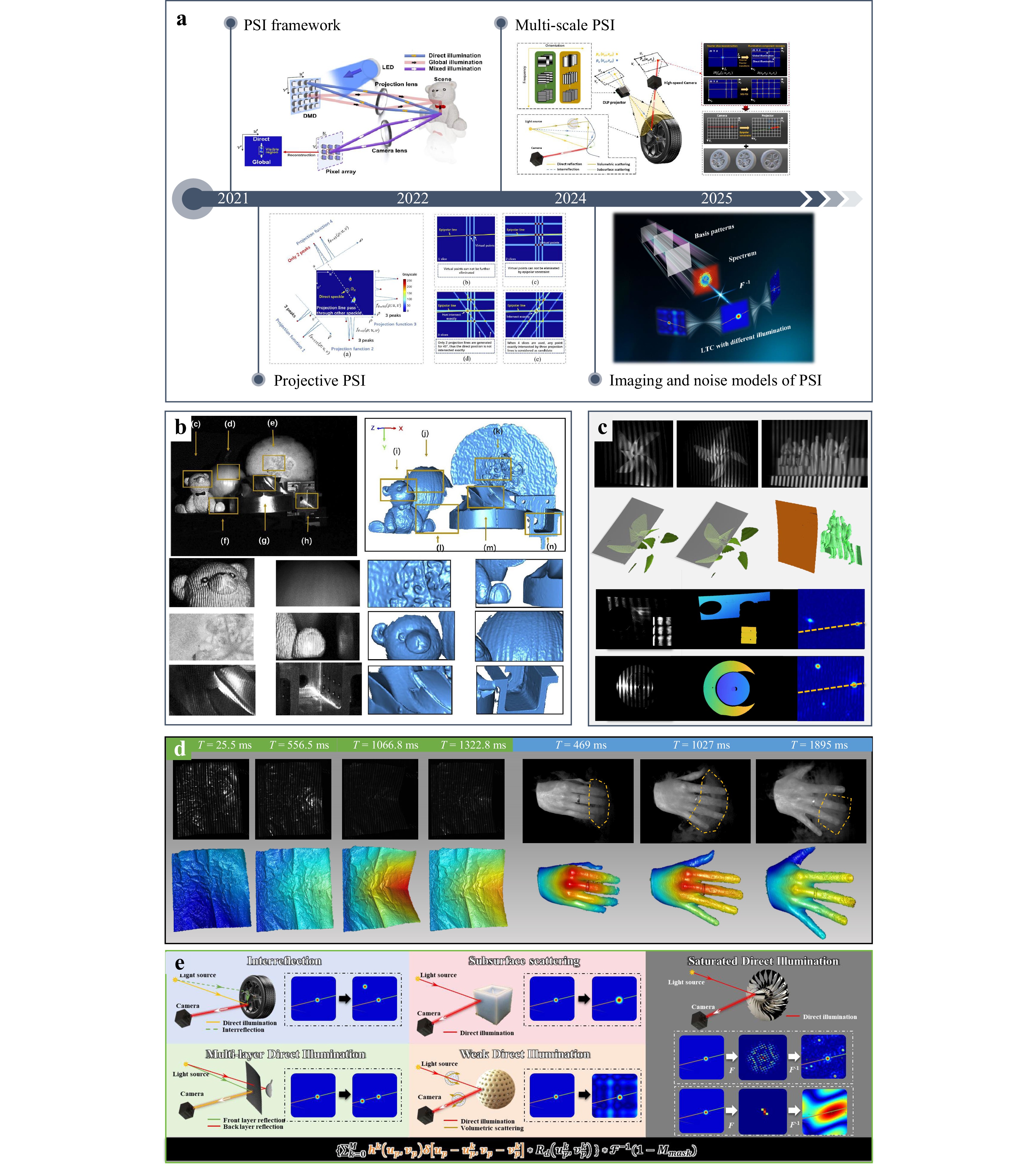
Fig. 23 CI-based 3D imaging. a Representative advances in CI-based 3D measurement. b PSI-based decomposition of direct and global illumination in mixed-reflectance scenes188. Dynamic MS-PSI reconstruction of c multi-layer structures and metals189,381 and d HDR scenes through scattering media190. e Imaging and noise models of PSI189.
To achieve general measurements under complex illumination conditions, the core task is to describe the light transport process with unpredictable paths. However, a normal array camera can only record the intensity distribution on the detected plane, and therefore, inverse problem-solving is indispensable for inverting the harsh reflection and transmission processes. Early CI-based strategies, such as primal-dual coding and homogeneous illumination encoding, demonstrated that LTC could be experimentally probed. They also enabled 3D measurements under challenging conditions, including specular reflections, scattering media, and strong lighting interference382–384. However, these approaches typically require coaxial set-ups and are thus difficult to integrate with standard structured light systems.
A more practical path has emerged from single-pixel imaging (SI), which leverages Helmholtz reciprocity to interchange the roles of projectors and detectors. In this paradigm, image formation is computationally achieved by projecting a sequence of patterns and reconstructing a scene from the aggregated intensity measurements. By extending this principle, Jiang et al. proposed PSI, in which each pixel of a conventional camera acted as an independent single-pixel detector. The PSI enabled the decomposition of direct and global illumination without requiring additional hardware. This made it possible to handle scenes with mixed reflectance types, including diffuse, specular, inter-reflection, and sub-surface scattering, as shown in Fig. 23b. Nevertheless, early PSI systems required an unaffordable large number of projection patterns, which limited their applicability to static scenes. To address this, projective PSI (pPSI) was developed by applying the Fourier slice theorem to reduce the dimensionality of LTC recovery, thus reducing the number of patterns to hundreds. More recently, multi-scale PSI (MS-PSI) has further improved the efficiency, requiring at least 15 projected patterns to achieve dynamic 3D measurements on multi-layer surfaces, HDR scenes, and scattering media, as shown in Fig. 23c, d190.
In addition, annular Fourier coefficient measurements have been introduced to improve encoding efficiency, and an efficient reconstruction algorithm for dual profilometry leverages Fourier coefficients together with epipolar line constraints to bypass dual-image reconstruction, thereby accelerating 3D reconstruction385–387. In addition to these experimental advances, theoretical models of PSI have begun to mature, incorporating both imaging and noise characteristics to explain its performance quantitatively, as shown in Fig. 23e. The proposed model elucidates light transport under complex illumination and the mechanisms that enable accurate PSI-based 3D imaging. It also quantifies the environmental noise effects and provides a framework for PSI error analysis.
PSI reconstructs geometric information through light transport modelling, rather than direct triangulation. This new computational 3D imaging framework provides a new pathway for general and robust measurements in environments that were previously deemed intractable. Apart from its proven superiority, many potential applications can be explored based on this architecture. Further utilization of direct components makes backlit 3D imaging, 3D imaging through flames, and underwater 3D imaging possible, which are difficult for existing techniques. In addition, the characterization of global components can be further studied for emerging imaging tasks such as flow field monitoring, material classification, multi-modal imaging, and functional imaging. Finally, broader applications may be considered after obtaining the LTC, such as point-spread function measurements, volumetric imaging, scattering imaging, and biomedical imaging. For more detailed discussions regarding the potential applications of PSI, readers can refer to the work of Chen et al.189.
Beyond PSI-related techniques, CI frameworks have also been introduced into a broader range of FPP methods to enhance system performance and expand application capabilities. For example, CI-based fringe super-resolution techniques388,389 exploit sub-pixel reconstruction strategies to overcome hardware resolution limits and improve spatial detail recovery. In scattering or turbid environments, descattering CI approaches enable the separation of encoded fringes and turbid media390, thereby enhancing reconstruction robustness under complex light transport conditions. In addition, compressive sensing-based fringe projection methods391 leverage sparsity priors to reduce the number of required projections while maintaining the reconstruction accuracy and improving the measurement efficiency. Therefore, the incorporation of CI principles extends FPP beyond conventional phase calculations, enabling higher resolution, improved robustness, and greater flexibility under challenging optical and practical constraints.
In summary, the participation of AI and CI has initiated a paradigm shift from geometry-based frameworks to data-driven and model-based architectures. This transformation is not a flash in the pan; rather, it is a continuous process. During this process, intelligence and computation are deeply integrated into every stage of 3D imaging, from illumination design and data acquisition to 3D reconstruction and error tracing. As these innovations continue to be made, FPP is evolving into a more intelligent, versatile, and cross-disciplinary technology. These advances are expected to reshape the 3D optical metrology in the coming years.
-
3D imaging technologies have made significant progress over the past decades. However, substantial new challenges have arisen from emerging measurement requirements. To this end, we will discuss several key challenges in 3D imaging technologies in this section and highlight the emerging research directions to provide potential solutions.
-
Traditional 3D measurement methods are typically developed based on the assumption of Lambertian reflection. However, in practical applications, the objects often exhibit diverse reflection characteristics. For example, metal surfaces may cause sensor saturation or significantly reduce the SNR, inter-reflection in concave structures introduces misleading light paths, and sub-surface scattering in biological tissues or polymers blurs fine structural details. Each of these cases violates the Lambertian assumption to varying degrees. Therefore, the direct use of conventional methods introduces errors or even fails to measure such multitype or mixed-surface scenarios.
To address these challenges, task-specific algorithm optimization is often required, which inevitably limits the universality of these methods. Although emerging AI- and CI-based methods have shown the potential to enhance generalization by learning from data or introducing higher-dimensional representations, they still suffer from critical issues, such as error non-traceability, reduced interpretability, and limited measurement efficiency. Moreover, for some special surfaces such as glass or other semi-transparent media, fringe information cannot be effectively captured in the visible spectrum. This leads to a complete measurement failure. Therefore, robust and generalized measurements of multi-type surfaces remain an open problem.
To improve the reliability and interpretability of AI-based approaches, it is vital to emphasise the use of physics-informed deep learning392–395. For measurement tasks, the "reliability-first" rule should be given priority. Therefore, more physical constraints should be embedded into the network design to mitigate the black-box nature of AI models and reduce the likelihood of unpredictable errors. In addition, a "divide-and-conquer" rather than "end-to-end" strategy is preferred. It is suggested that AI should be assigned to perform multiple simpler, well-defined sub-tasks rather than solving the entire problem holistically to attain higher certainty of the measurement results. The other benefit is that decomposing the measurement task into physically constrained sub-problems enables the integration of hybrid learning396,397. Distinct models can be optimized for different sub-tasks to maximize the synergy between physical modelling and data-driven learning. Another pivotal direction is measurement uncertainty estimation and error traceability376,398–401. Unlike imaging tasks, meteorological measurements require high repeatability and traceability. Therefore, uncertainty quantification is indispensable in AI-based metrology. Although we can tolerate such errors, we must be able to recognize, quantify, and predict them. This capability allows operators to identify unreliable data and enhances the measurement robustness. In summary, enhancing the traceability, repeatability, and reliability is fundamental to data-driven AI-based measurement methods.
For CI-based methods, improving the encoding and measurement efficiencies is equally essential. This requires rethinking and optimizing the entire imaging pipeline. Imaging targets have shifted from traditional image-driven digital processing to task-driven computational imaging. The system transmits only the core information necessary for the measurement task. Therefore, it can maximize the information throughput. For example, in PSI, the essential task is the localization of direct components rather than the reconstruction of full light transport coefficient maps. In this context, dimensionality-reduction principles, such as the Fourier slice theorem402–404 or position-invariance theorem190 can be incorporated to drastically reduce the required encoded information. In addition, compressive sensing (CS)405–411, inverse-problem parameter optimization412–416, optimal spectral sampling417–421, spatiotemporal multiplexing422–424, and hardware acceleration127,425 can be leveraged to further boost the performance. In essence, CI-based strategies aim to transmit the most critical information using efficient computational imaging means.
-
In addition to surface reflection properties, disturbances during light transmission and illumination conditions have a significant effect on 3D imaging. For instance, outdoor measurements often encounter strong light interference426, while in metal additive manufacturing, real-time monitoring through dust-laden environments suffers from volumetric scattering. Moreover, underwater 3D imaging faces flow disturbance and impurity interference 427, and in material sorting, the rapid classification of objects embedded within semi-transparent surfaces is challenged by multiple direct transmission paths. Moreover, non-uniform reflectance surfaces428–431 or stepped regions432 with depth discontinuities may lead to information mixing, where a device's defocusing433 or non-linear response434 degrade the quality of raw measurements. In these scenarios, the propagation of light no longer follows the conventional "point-to-point" single reflection model, and it leads to the mixing or loss of depth-encoding information. Although PSI and related methods can separate parts of the global illumination components, their effectiveness drastically diminishes once the indirect illumination components become dominant. Under such extreme conditions, the problem often evolves into 3D imaging through scattering media or even non-line-of-sight (NLOS) 3D imaging. Both represent cutting-edge research challenges, with substantial theoretical and technical difficulties. However, for structured light projections, systematic attempts to address these problems are still scarce. Hence, achieving robust multi-path scene 3D imaging remains an unsolved challenge.
To address these challenges, concepts can be borrowed from other computational imaging domains, such as compressive sensing407,435,436, scattering imaging437–440, NLOS imaging441–445, and biomedical imaging446–450. These research areas share significant mathematical and physical similarities with 3D imaging problems under multi-path propagation. The key challenge is decoupling and reconstructing multiple depth components that are spatially or temporally compressed into a single measurement.
In multi-path 3D imaging, the mathematical formulation closely resembles that of compressive sensing, with the goal of recovering high-dimensional information from compressed observations. Various coding and decoding strategies have been proposed for typical CS-based imaging systems, such as single-pixel imaging197,451–454, compressed ultrafast photography (CUP)455,456, and snapshot compressive imaging (SCI)457. These frameworks can be adapted to solve depth compression problems. For example, multi-layer 3D reconstruction can be transformed into an equivalent single-layer inverse problem through CS-based encoding and decoding, thus enabling volumetric imaging of scattering or semi-transparent media458. As the turbidity of the transmission medium increases and the imaging environment degrades, the problem gradually approaches the regimes of scattering imaging and NLOS imaging. In scattering imaging, techniques such as adaptive optics437,459–462, wavefront shaping463–465, transmission matrix inversion466–468, deep-learning-assisted reconstruction469–472, and optical memory effect439,473–475 have demonstrated the ability to recover clear images from strongly scattered media. These approaches can be integrated into FPP to facilitate the transmission and reconstruction of depth-encoded 2D intensity images. Once a clean 2D image is recovered, conventional 3D reconstruction algorithms can be used to achieve 3D imaging using the scattering media.
Similarly, NLOS imaging focuses on recovering ballistic or direct light components from diffusely scattered light. Representative strategies include intensity-based methods476–479 that reconstruct hidden geometries by exploiting occluder-induced modulation or surface albedo cues. In contrast, time-of-flight (ToF) approaches443,480–482 use ultrafast photon detectors to model the multiple bounces of light. These techniques can be used to extract direct illumination components under multi-path or scattering conditions and guarantee more accurate depth reconstruction in complex environments.
In biomedical imaging, light propagation through biological tissues also suffers from strong scattering, which causes a trade-off between penetration depth and spatial resolution. Conceptually, this is similar to volumetric imaging using thick-scattering media in multi-path 3D measurements. Thus, techniques developed for biomedical optics can offer valuable insights. These techniques include physical-optical methods such as wavelength conversion483–487, energy conversion488–492, and phase compensation493–496, and computational optical techniques such as digital phase conjugation497-500, iterative wavefront shaping501-503, transmission and reflection matrix methods504-508, and autocorrelation imaging444,509-511. By integrating these concepts, multi-path 3D imaging can potentially achieve deeper and more robust volumetric reconstructions in turbid or occluded environments.
-
Instead of geometric information, advanced systems are expected to simultaneously extract physiological, material, and mechanical parameters for multi-functional and multi-modal capabilities. For instance, physiological parameter measurements based on spectral or thermal imaging are crucial for non-invasive medical diagnostics512-515. Material identification and maturity detection are important for food quality control and ripeness assessment516. Mechanical parameter measurements such as deformation or strain monitoring430,517-522 are helpful for structural health evaluations in engineering. In addition, chromophore or functional group imaging enables the investigation of optical properties523,524, which are required for biomedical and chemical analyses. Although researchers have attempted to expand the measurement dimensions and modalities of structured light systems, realizing such integrated functionalities within a single 3D imaging framework remains highly challenging. Different modalities require distinct illumination spectral bands, sensing mechanisms, or computational models, and therefore, it is difficult to balance the measurement efficiency, accuracy, and system complexity. Moreover, cross-modal data fusion introduces additional challenges in calibration, error propagation, and joint encoding–decoding of multi-dimensional signals. Therefore, multi-functional and multi-modal imaging still requires in-depth research for future 3D imaging systems.
Further advances are expected in the co-optimization of sensing-storage-computation within a unified computational framework525. This paradigm represents a shift from traditional sequential imaging pipelines towards a holistic optimization process. Optical acquisition, data processing, and interpretation are no longer treated as independent stages; instead, each component is jointly designed and mutually informed. Through collaborative design of optical encoding, signal acquisition, and computational reconstruction, these systems can achieve optimal performance. For example, the inefficiency and complexity hinder the development of conventional spectroscopic systems because cumbersome elements such as prisms, gratings, and spectral filters are required. In recent years, there has been a surge in computational snapshot hyperspectral imaging techniques driven by compressive sensing theory and computational photography. Representative examples include the computed tomography imaging spectrometer (CTIS)526-528, coded aperture snapshot spectral imaging (CASSI)529-532, broadband hyperspectral image sensors533-535, and sub-ångström snapshot spectroscopy536. These methods have led to significant progress in coded-aperture modulation, high-sensitivity sensor fabrication, and large-scale high-resolution spectral reconstruction. The jointly optimized strategies enable snapshot acquisition of high-dimensional spatial–temporal–spectral information. They allow the real-time reconstruction of multi-modal parameters such as material composition, tissue constituents, blood oxygen saturation, and atomic spectroscopy.
In summary, 3D imaging currently faces challenges such as complex surface reflections, multi-path transmission, and multi-functional sensing. Table 2 summarizes these representative challenges and their applications and provides an overview of the key directions and considerations for future 3D imaging research.
Category Challenges Applications #1: Multi-type surface 3D measurement
Measurement under complex reflection conditions.- HDR surface measurement
- Transparent surface measurement
- Inter-reflection surface measurement
- Sub-surface scattering surface measurement- Inspection of reflective/translucent objects
- Heritage preservation
- Quality control for optical components
- Biomedical surface scanning (skin, tissues)#2: Multi-path scene 3D imaging
Imaging under complex transmission conditions.- 3D imaging under strong light interference
- Multi-layer 3D imaging
- 3D imaging through scattering media
- Non-line-of-sight 3D imaging- Robotics for occluded object detection
- Through-wall or foggy environment imaging
- Industrial inspection of layered structures
- Surveillance and search-and-rescue applications#3: Multi-functional and multi-modal imaging
Imaging with extended applications.- Physiological parameter measurement
- Material identification
- Maturity detection
- Mechanical parameter measurement
- Chromophore imaging- Medical diagnostics
- Food quality and ripeness assessment
- Material composition analysis
- Strain/deformation monitoring
- Optical properties measurementTable 2. An overview of representative challenges and their promising applications for future directions of 3D imaging research.
-
The continuous evolution of novel imaging hardware has provided new opportunities for 3D imaging, particularly when co-optimised with reconstruction algorithms. Rather than being considered independently, hardware and algorithms are increasingly being designed together to maximize sensing performance. Polarization cameras, for example, provide additional polarization information beyond the intensity. When coupled with polarization-aware reconstruction models, they enable the robust 3D measurements of transparent or reflective objects291,537-539 or facilitate underwater imaging through polarization-based dehazing algorithms540-543. Thermal cameras can detect information in the infrared waveband and shape recovery of refractive materials, such as glass and plastics, by encoding structured light in the temperature field544-548. Multi-spectral and hyperspectral cameras provide multi-channel signals with significant intensity differences. Co-designed spectral–geometric reconstruction frameworks not only enhance HDR depth imaging544,545 but also enable the joint estimation of material and physiological parameters549-552. Event cameras record images using asynchronous reconstruction algorithms, which guarantees the ability to detect micro-scale brightness change553-558. This reduces redundant data and ensures dynamic reconstruction under fast motion or extreme illumination conditions. Single-photon avalanche diode (SPAD) cameras provide single-photon sensitivity with picosecond timing precision. When integrated with photon-statistics-based depth estimation or time-correlated computational models, accurate depth recovery can be achieved under ultra-low-light or strong sunlight conditions149. Finally, metasurface-based optical devices offer a method for manipulating amplitude, phase, polarization, and wavelength at the sub-wavelength scale. The newly modulated dimensions and scales have the advantages of compactness, extended depth of field, low power consumption, and multi-functional wavefront modulation for 3D imaging559-566.
These examples demonstrate a trend shift in the co-optimization of systems and algorithms. Imaging and computation are unified within a collaborative framework to make full use of the emerging hardware. This collaboration provides 3D imaging systems with enhanced detection capabilities, adaptability, and intelligence.
-
CI has high interpretability and generalization based on rigorous high-dimensional physical modelling. In addition, it provides opportunities for handling multiple types of surfaces and complex illumination scenarios. However, this physical-model-driven approach often succeeds at the expense of massive measurements or complicated algorithms. In contrast, AI directly learns efficient non-linear mappings from data and enables fast, flexible, and noise-robust 3D reconstruction. However, its black-box nature reduces measurement interpretability. Therefore, it is difficult to trace or quantify measurement errors, which is essential for high-precision and reliability-demanding applications. These characteristics suggest that the CI and AI are complementary partners rather than competitors. CI ensures a physically grounded and interpretable framework, whereas AI provides efficiency, adaptability, and robustness. Like "the left hand of physics and the right hand of intelligence", their cooperation can overcome the inherent weaknesses of each side and forms a powerful solution for tackling complex tasks under extreme environments. Building on this synergy, we envision several future research directions. First, developing hybrid CI-AI frameworks that integrate physical priors directly into neural network architectures can enhance interpretability while maintaining computational efficiency. Second, adaptive acquisition strategies guided by AI can lead to an optimal coding strategy for CI, thereby enabling faster and more resource-efficient 3D imaging. Third, uncertainty quantification methods can be embedded to provide confidence estimates for reconstructed surfaces, thereby addressing reliability concerns in precision-critical applications. Finally, extending CI-AI methods to handle diverse real-world scenarios, such as dynamic scenes, mixed scattering, and non-Lambertian surfaces, will broaden the applicability of 3D imaging techniques. Ultimately, the convergence of CI and AI will shape the future of the next-generation computational 3D imaging techniques.
-
In this paper, we have presented a comprehensive review of FPP. This review highlights the vast advancements in theory, techniques, and applications as the field extends towards extreme measurement scenarios. This review traces the development of FPP over the last four decades and divides it into three major phases. Basic theories and implementations were established in the foundation phase (1983–2006), while advances for improved accuracy, speed, and expanded applications were reviewed during the booming phase (2007–2018), and the breakthroughs enabled by AI and CI were discussed in the transformative phase (2019–present). This review summarizes the challenges associated with complex surface reflection, multi-path light transmission, and multi-functional sensing. Looking forward, the future trajectory of FPP will be driven by the co-optimization of the system and algorithms, and the convergence of CI and AI.
Fig. 24 is used to wrap up this review. With the continuous advancement of computational frameworks, data processing capabilities, and hardware architectures, traditional phase analysis-based geometric triangulation methods are progressively evolving toward inverse problem-driven computational 3D imaging. These developments pave the way for intelligent 3D sensing systems with unprecedented adaptability, enabling reliable operation across diverse conditions and scales in industrial inspection, advanced manufacturing, biomedical imaging, and scientific exploration.
Fig. 24 Technical development from geometric triangulation to computational 3D imaging.
-
We gratefully acknowledge Prof. Xianyu Su for his invaluable contributions to this work and to the field of structured-light 3D reconstruction, and remember him with deep respect and lasting appreciation. This research was supported by the National Natural Science Foundation of China (62575193, 62575192, 62505076, and 62205226), the National Postdoctoral Program for Innovative Talents of China (BX2021199), the General Financial Grant from the China Postdoctoral Science Foundation (2022M722290), and the Key Science and Technology Research and Development Program of Jiangxi Province (20224AAC01011).
Review of fringe projection profilometry: from geometric triangulation to computational 3D imaging
- Light: Advanced Manufacturing , Article number: 74 (2026)
- Received: 12 December 2025
- Revised: 22 April 2026
- Accepted: 23 April 2026 Published online: 03 June 2026
doi: https://doi.org/10.37188/lam.2026.074
Abstract: With the rapid advances in digital technologies and intelligent manufacturing, three-dimensional (3D) imaging based on fringe projection has laid the foundation for machine vision, industrial metrology, and interdisciplinary applications. This review provides a comprehensive overview of fringe projection profilometry (FPP), which is a widely adopted technology in the 3D imaging landscape. First, we outline the fundamental principles, implementation procedures, and historical developments of FPP. Next, we present the continuous advances in algorithms, hardware, and applications that collectively push FPP towards increasingly challenging measurement scenarios. Subsequently, we provide a dedicated discussion to explain the transformative roles of artificial intelligence (AI) and computational imaging (CI), delineating how their progress is initiating a shift from traditional geometric approaches towards computational 3D imaging. The current challenges and emerging trends in 3D imaging are further identified and discussed. Looking ahead, FPP is expected to evolve into a next-generation 3D imaging technique, achieving unprecedented accuracy, efficiency, and adaptability through the co-optimization of systems with algorithms and the convergence of AI and CI, thereby empowering more complex requirements across industrial, biomedical, and scientific domains.
Rights and permissions
Open Access This article is licensed under a Creative Commons Attribution 4.0 International License, which permits use, sharing, adaptation, distribution and reproduction in any medium or format, as long as you give appropriate credit to the original author(s) and the source, provide a link to the Creative Commons license, and indicate if changes were made. The images or other third party material in this article are included in the article′s Creative Commons license, unless indicated otherwise in a credit line to the material. If material is not included in the article′s Creative Commons license and your intended use is not permitted by statutory regulation or exceeds the permitted use, you will need to obtain permission directly from the copyright holder. To view a copy of this license, visit http://creativecommons.org/licenses/by/4.0/.

 DownLoad: