






HTML
-
Ultrathin fibre-endoscopic microscopes (endo-microscopes) enable minimally invasive, microscale optical imaging1, 2. Such devices ($\phi \approx$ 100–1,000 µm) are promising for reaching structures in small cavities that are inaccessible to bulk optics, thus are ideal for applications in biomedical imaging3, 4 and highly integrated biophotonics5, 6. Because the surroundings typically lack inherent lighting for endo-microscopy, the endoscope itself must provide illumination, ideally co-integrated within the same imaging-fibre to minimise the total endoscope diameter. However, this integration is particularly challenging to realise for “simple” bright-field illumination, because illumination light partially reflects at the back-end of the fibre-endoscope and superposes the endoscopic image at the sensor, thereby deteriorating the image contrast7, 8. The reflected illumination and the imaging signal are difficult to separate because they have the same wavelength and the light is unpolarised. State-of-the-art endoscopes solve this problem by using separate illumination fibres around a central imaging channel, at the expense of enlarging the endoscope diameter9, 10.
Several other strategies have been investigated to compactly co-integrate illumination and imaging. Index matching at the fibre facet reduces the critical back-reflections at the fibre back-end, providing sufficient image contrast. However, this approach requires invasive changes to the back-end imaging system of the endoscope11, which is impractical when combined with closed commercial imaging systems. Furthermore, these methods may require hazardous index-matching liquids and custom objective lenses7, 12. Lensless endoscopes use multimode-fibres or coherent fibre bundles (CFBs) to illuminate an object and collect the back-scattered light. Subsequent algorithmic image reconstruction elegantly bypasses the acquisition of a “real” endoscopic image8, 13−16, avoiding contrast issues caused by light reflected from the back-end facet of the fibre. These lensless endoscopes can be ultrathin ($\phi \approx 100$ µm), but are currently limited in practice by sophisticated back-end hardware requirements (spatial light modulators, digital-mirror devices), minute-long frame-acquisition times, short endoscope lengths, and sensitivity to bending. An easy-to-use, robust, and real-time-capable ultrathin endoscope with co-integrated illumination and bright-field microscopy has not yet been developed.
Advances in additive manufacturing using multiphoton 3D-printing17−21 have provided new methods to produce compact ($\phi \ll 1$ mm), highly integrated micro-optics for fibre-endoscope tips. Their potential has been demonstrated in light-guiding and illumination-shaping applications22, 23 and miniaturised imaging optics with microscopic resolution24−26. Co-integrated, monolithic illumination and imaging systems can ideally leverage flexible 3D-printing technology and produce ultracompact, matched illumination and imaging optics. Such combined systems have not been realised thus far. Furthermore, 3D-printed imaging micro-optics are restricted to gaseous laboratory environments. which is a major limitation because life sciences and biomedical imaging require operations in immersion liquids and biological fluids. Recently, we overcame this fundamental limitation with a new method to produce 3D-printed micro-optics for direct liquid immersion27, and conceptually demonstrated a simple point-illumination optical system. Monolithic and ultracompact ($\phi \ll 1$ mm) 3D-printed immersible systems for full-field imaging at endoscope tips have not yet been developed.
In this study, we leverage 3D-printed micro-optics to realise a new concept for co-integrated illumination and endoscopic immersion microscopy within a single compact and robust CFB endoscope (Fig. 1). We use multiphoton 3D-printing to produce micro-optics that divide the CFB cross-section into edge-ring illumination and a central imaging path. At the back-end of the endoscope, we achieve easy-to-integrate ring-illumination with a 3D-printed ring diffractive optical element (DOE) at the CFB for off-axis illumination-light coupling. At the front-end of the endoscope, we co-integrate an immersion endo-microscope with a ring-illumination waveguide-system in a compact ($\phi$ = 550 µm) 3D-printed monolith.
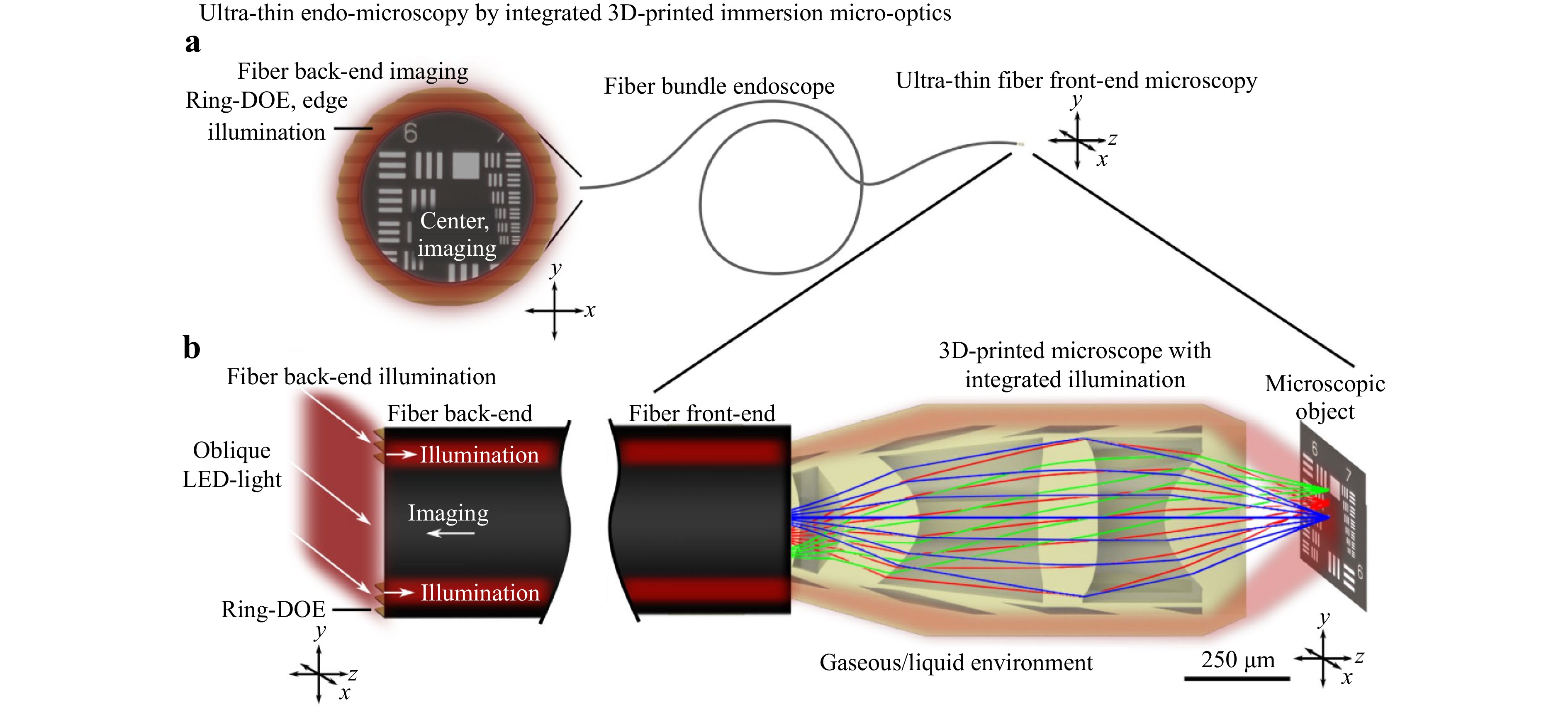
Fig. 1 Concept. a 3D-printed micro-optics enable a new approach to the fabrication of ultrathin endoscopes by co-integrating illumination and imaging within a single fibre bundle. When applied in confined cavities, they allow the imaging of hidden structures, that are inaccessible to bulk optics. b At the back-end of the endoscope, we combine oblique LED-illumination with a 3D-printed ring-shaped diffractive element to realise an easy-to-implement ring-illumination. This leaves the centre of the endoscope clear of illumination artifacts for imaging. At the fibre front-end, we combine a tailored illumination-waveguide and an immersion endo-microscope within a compact 3D-printed monolith. This approach provides smaller and more robust endoscopes than those developed with state-of-the-art manufacturing methods.
We demonstrate a manufacturing strategy for highly integrated 3D-printed micro-optics and apply it to high-resolution endo-microscopy in air and liquid immersion. Our single fibre endoscope prototype combines thinner, more robust, and more versatile endo-microscopy compared to state-of-the-art alternatives. This provides a promising platform for future flexible ultracompact co-integrated illumination and imaging fibre-endoscopes.
-
We design a tailored ring DOE that covers $ \approx $33% of the CFB area to create a ring-illumination at the CFB back-end. It locally couples light from oblique illumination angles to the edge area of the CFB by aligning the diffracted illumination light (2nd order, Methods A) from angles exceeding the native numerical aperture (NA) of the CFB with the optical axis of the CFB. In the imaging area outside the ring DOE, no illumination light can enter the CFB or be reflected directly from its back-end into the imaging-beam path; therefore, the ring DOE decouples the imaging and illumination modalities within the single fibre bundle. This oblique illumination is an easy and noninvasive add-on to existing and possibly enclosed commercial back-end imaging systems.
We manufacture the DOE using multiphoton 3D-printing directly at the back end of the CFB (Fig. 2a, Methods B). During the printing process, we first place a 10 µm-thick adhesion base on the CFB to ensure a strong mechanical connection. We then add the DOE with a thickness of 2.05 µm on top. To improve the homogeneity of the printed DOE structure, we bisect the DOE and sequentially print the two halves (details are provided in Methods C).
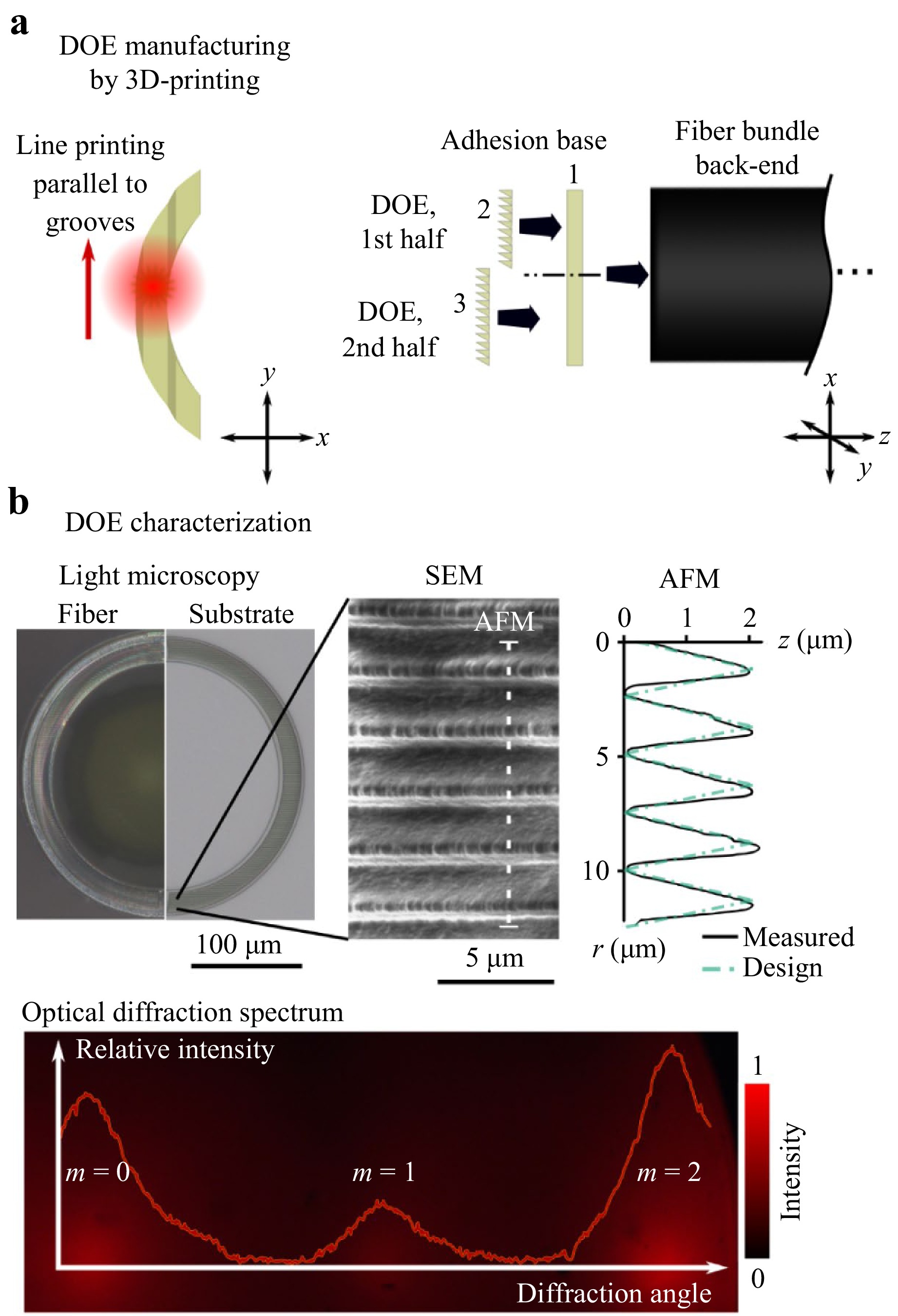
Fig. 2 Fibre back-end micro-optics. a We fabricate the ring DOE via multiphoton 3D-printing at the back-end of the CFB. For robust manufacturing, we bisect the DOE and print its halves sequentially on top of an adhesion base. b Light microscopy confirms successful DOE manufacturing on the CFB tip. Scanning electron microscopy qualitatively shows well-defined blazed DOE grooves, and atomic force microscopy quantitatively confirms close agreement with the DOE design. The optimised optical-diffraction spectrum exhibits its maximum peak at the second diffraction order $ \text{m} = 2 $ with $ \theta$ = 30°.
Light microscopy confirms the successful fabrication of the DOE at the CFB back-end (Fig. 2b). For comprehensive structural characterisation (Methods C), we additionally fabricate a DOE on a glass substrate. Scanning electron microscopy reveals smooth and even structures, and the profile obtained by quantitative atomic force microscopy closely matches the optimised groove shape. The experimentally measured optical diffraction spectrum of the DOE confirms the preferred second-order diffraction with $ \theta$ = 30°, as designed. Residual zero-order diffraction is likely caused by surface roughness due to the printing-discretisation, and the residual difference from the ideal design shape. Erroneous light at $ m=0, 1 $ is lost for illumination but, crucially, is not back-reflected to the imaging sensor; hence, it is irrelevant for the imaging contrast in our approach.
-
For immersion endo-microscopy, we optimise a compact multilens objective using sequential ray-tracing optimisation (Fig. 3a, Methods D). The system comprises four lenses with eight optical surfaces to relay rays from the microscopic object to the image plane on the CFB front-end. The first flat surface is in direct contact with the CFB. The following six surfaces are aspheric and face air. The last optical surface is in contact with the gaseous ($ {n} = 1 $) or liquid ($ {1.33} \lt {n} \lt {1.4} $) environment around the CFB front-end. To reduce aberrations (defocus and spherical aberrations) caused by a possible refractive-index mismatch of the variable surrounding media, we minimise the refractive power of the last surface by matching the lens curvature to the incident-light wavefront. As a result, our design achieves a consistent focusing quality (Strehl ratio) and working distance within $ 1 \lt {n} \lt 1.4 $, while the NA and magnification $ \varGamma $ vary almost linearly with the refractive index ($ {0.4}<{NA}<{0.55} $, $ {0.98} \lt \varGamma \lt {1.35} $ for $ 1 \lt {n} \lt {1.4} $). The optimised endo-microscope achieves a diffraction limited Strehl ratio $ \gt {0.8} $ over an object plane with a diameter of $\phi _\text{obj}$ = 140 µm. The key optical-system parameters are listed in Supplement 1.
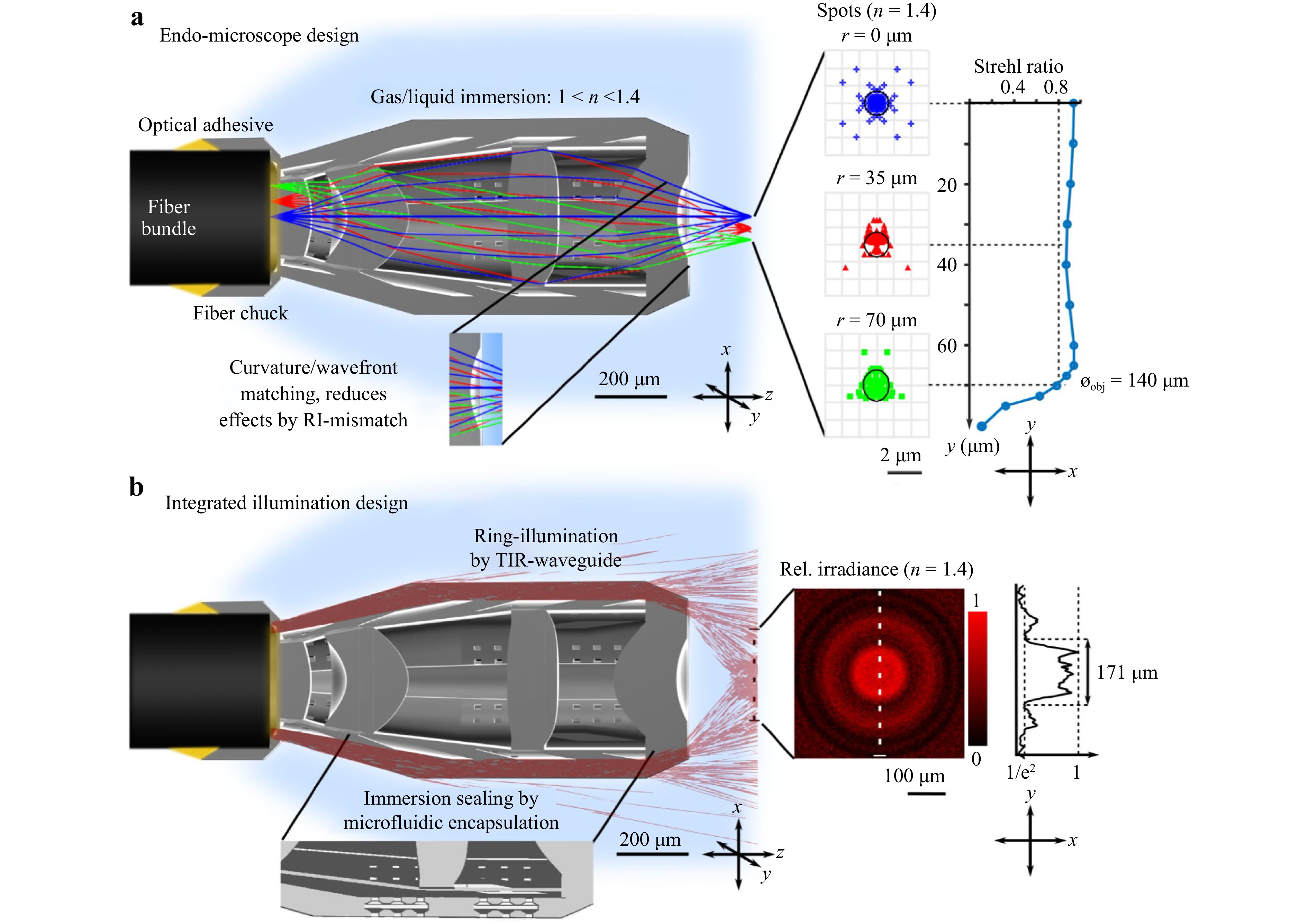
Fig. 3 Fibre front-end micro-optics design. Monolithic 3D-printed micro-optics allow co-integrated illumination and microscopy. a The diffraction-limited 3D-printed endo-microscope images the object onto the image plane at the CFB front-end, with an object-space NA up to 0.55. To enable operation in various immersion media, we optimise the last optical surface to minimise aberrations by refractive-index mismatch. b We co-utilise the encapsulating walls around the endo-microscope to guide light from the CFB front-end towards the object plane of the endo-microscope for homogeneous illumination.
-
For integrated illumination, we optimise a waveguide structure that redistributes the ring-illumination light from the outer fibre cores at the CFB front-end to a homogeneously illuminated area at the object plane of the endo-microscope (Fig. 3b, Methods E). We co-utilise a circular immersion-shielding wall around the endo-microscope, designed based on microfluidic methods from Ref. 27 (Methods F), to conduct light to the endo-microscope tip via total internal reflection at surfaces between the 3D-printed material (IP-S, $ {n} = 1.51 $, Nanoscribe GmbH, Eggenstein-Leopoldshafen, Germany) and surrounding media ($ 1 <{n} \lt 1.4 $). At the very tip, an optimised wedge TIR-structure redirects and concentrates the light to the endo-microscope field of view (FOV). The nonsequential simulation predicts a homogeneously illuminated disc of $\phi \approx 170$ µm, which covers the diffraction-limited object field of the endo-microscope of $\phi _\text{obj}=140$ µm.
-
We print the integrated CFB front-end optics on sacrificial support structures on a carrier glass substrate (Fig. 4a,1), followed by standard development steps (Methods G). We choose this procedure because it allows for the efficient batch fabrication of numerous endo-microscopes in a single printing procedure, running overnight or over the weekend. Subsequently, the prefabricated endo-microscopes on the substrate can be easily combined with the CFB endoscope in a postassembly step. Therefore, we wet the CFB-tip with a UV-adhesive (IP-S) and approach the 3D-printed fibre chuck (Fig. 4a,2). After alignment, we fix the connection via UV-curing (Fig. 4a,3) and detach the endo-microscope from the substrate by breaking predetermined weak points in the support structure, similar to a method used in Ref. 28.
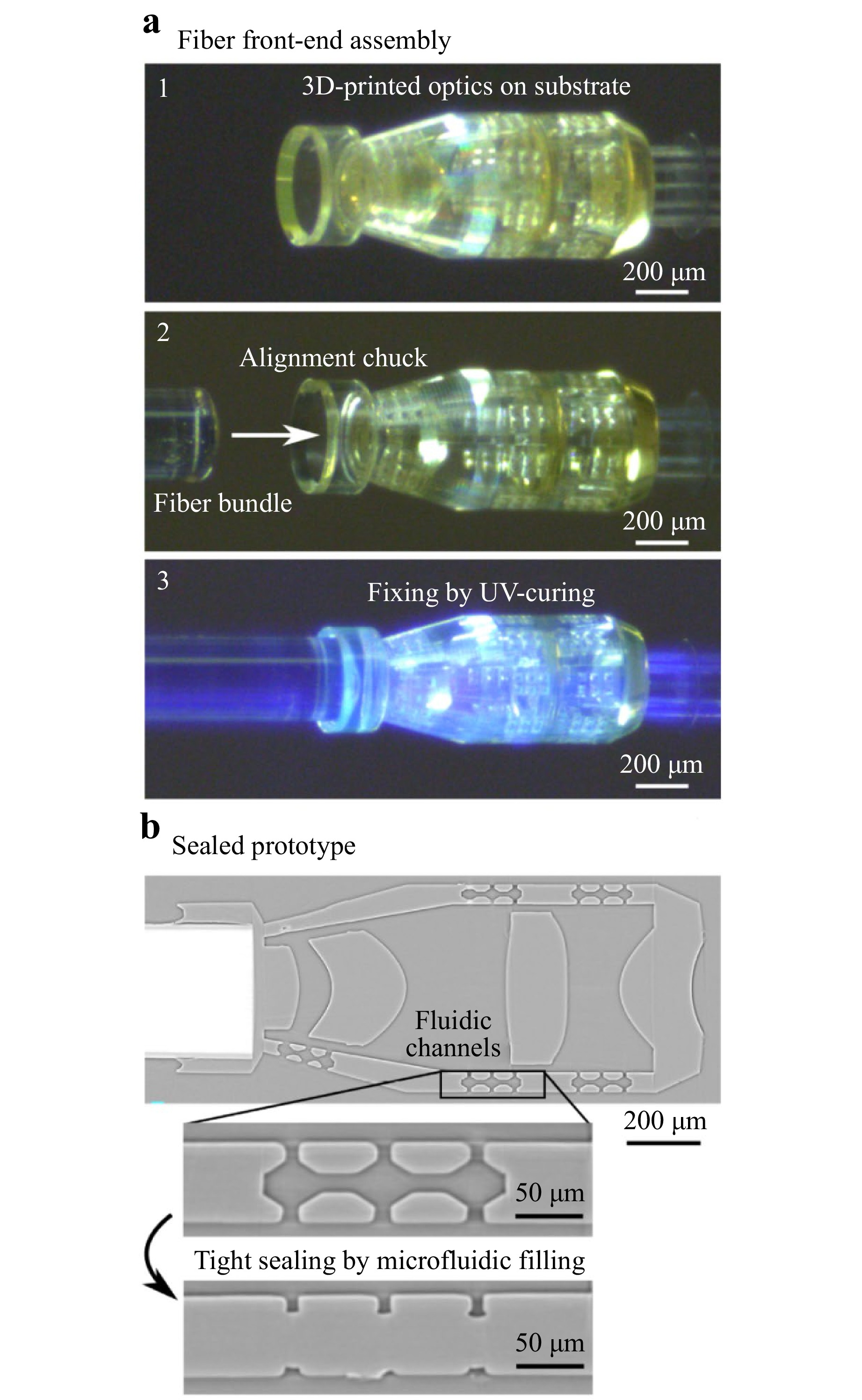
Fig. 4 Fibre front-end micro-optics manufacturing. a We print the monolithic optical system on sacrificial support structures on a glass substrate (1). Then, we connect it to the CFB front-end (2) by fixing it with UV adhesive (3). b We then seal the optics by filling the microfluidic encapsulation with a UV-sensitive liquid. X-ray microtomography imaging confirms successful sealing, providing tight encapsulation against surrounding liquids and smooth illumination-waveguiding by total internal reflection.
Following assembly, we seal the endo-microscope against the surrounding liquids using a recently developed microfluidic sealing method (Methods G27). In this process, we use capillary action to load the microfluidic channels integrated into the surrounding waveguide with a UV adhesive. Through subsequent UV-curing, we permanently close these microfluidic channels, providing a continuous layer of material inside the waveguide structures and sealing the endo-microscope against environmental liquids. Using X-ray microtomography, we confirm successful microfluidic sealing (Methods H, (Fig. 4b), and the well-aligned connection between CFB and the attached endo-microscope.
-
We first validate the integrated illumination of the endo-microscope by observing the irradiance at the object plane (Fig. 5, Methods I). For this experiment, we illuminate the ring DOE at the CFB back-end obliquely ($ \gamma$ = 30°) with an LED light source. We acquire the projected object-plane illumination with an observation microscope in vis-à-vis configuration in air and liquid immersion. The measurements in air confirm that the integrated ring-illumination covers $ \approx 80 \% $ of the optimised object-field diameter of the endo-microscope ($\phi _\text{illu}$ = 110 µm of $\phi _\text{obj}$ = 140 µm, $ 1/{\rm e}^2 $-intensity threshold), and the full FOV in liquid-immersion oil ($\phi _\text{illu} \approx\phi _\text{obj} \approx $140 µm).
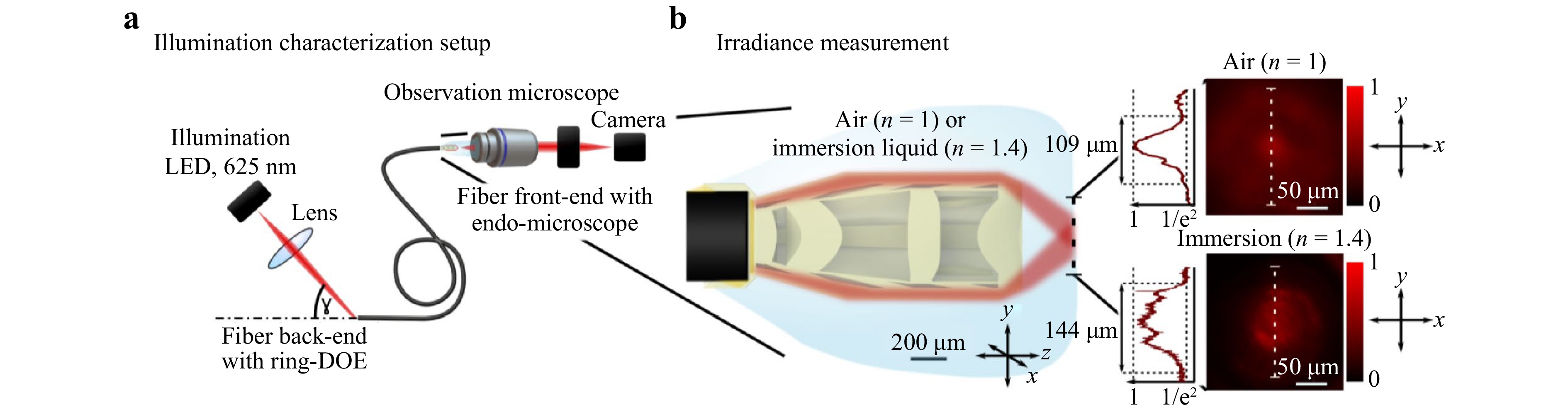
Fig. 5 Experimental ring-illumination characterisation. a We measure the illumination-plane intensities in air and liquid immersion with an observation microscope, opposite to the 3D-printed micro-optics at the CFB front-end. b The measured illumination irradiance largely covers the optimised FOV of the endo-microscope.
For the imaging experiments, we add a microscope to our back-end optical setup (Fig. 6, Methods J). Then, we approach the microscopic objects with the CFB-tip endo-microscope and exclusively illuminate using the integrated ring-illumination. We acquire images with exposure times ranging between 150 and 300 ms, enabling the acquisition of multiple frames per second. The exposure time and frame rate are limited by the illumination power available at the sample plane. We measure the illumination power and losses and discuss possible improvements to increase the illumination brightness of the sample in Supplement 2. The pixelation effect of the CFB impairs visual pattern recognition; therefore, we apply image processing to reduce this effect at the expense of inevitable edge-blurring effects29 (Methods K). Supplement 2 provides the unfiltered images and discusses the filtering effects.
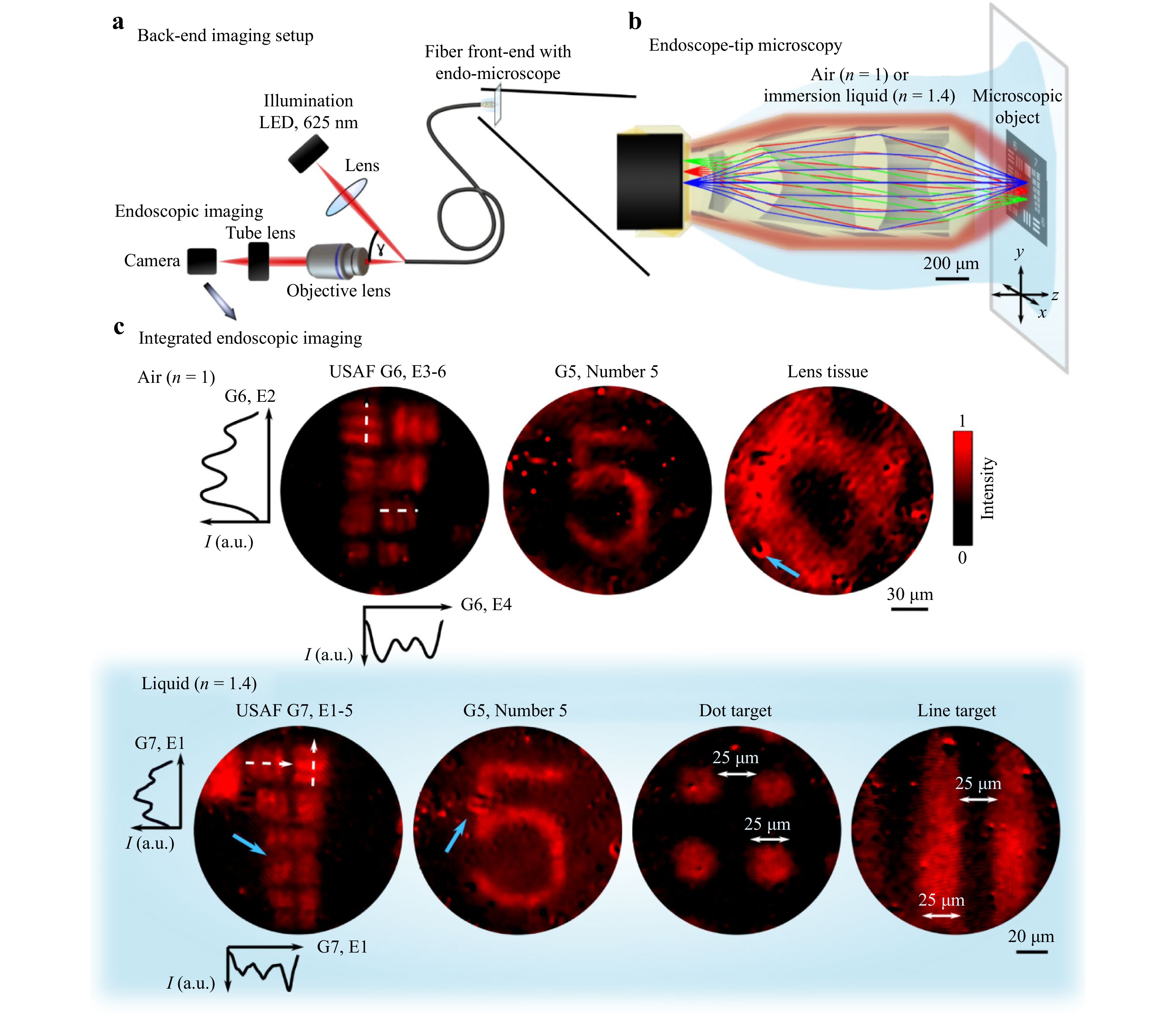
Fig. 6 Endo-microscopic imaging experiments with co-integrated ring-illumination. a We illuminate the back-end of the CFB obliquely with an LED, and acquire images with a microscope. b We place microscopic objects in the object plane of the fibre front-end endo-microscope, and irradiate with the integrated illumination. c The acquired images confirm microscopic imaging resolution over the optimised FOV, both in air and in liquid immersion. Larger structures from different materials (low-reflectance chrome on glass, organic fibre lens tissue) may be imaged. The blue arrows indicate obscuration-artifacts caused by light-scattering at defective CFB-cores. The white dashed lines indicate cross sections through the intensity profiles of the images. G: group. E: element.
We confirm the microscale imaging resolution by resolving the elements of United States Air Force (USAF)-test chart group 6 element 3 in air (line width = 6.2 µm) and group 7 element 1 in immersion (line width ≈ 3.5 µm) (Fig. 6c). Next, we observe large-scale structures with fine-features from different materials (low-reflecting chrome: enumeration “5” in the USAF-test chart, 25 µm-spaced dot-/line patterns; organic fibre lens tissue). These are all distinguishable across the endo-microscope FOV. Significant bending of the endoscope during the imaging procedures is possible (Supplement 2). The experiments demonstrate successful illumination and microscopic imaging of different materials in air and liquid environments. Compared with imaging in a standard epi-illumination configuration, our integrated ring-illumination concept shows an $ \approx 2.5 \times $ higher imaging contrast (Supplement 2).
-
A manufacturing process, suitable for possible future high-throughput fabrication, must be precise and repeatable. For the approach presented in this work, possibly critical manufacturing steps include the multiphoton 3D-printing of the front- and back-end optical components, and adhesion step of the 3D-printed endo-microscope to the CFB front-end.
Optical surfaces 3D-printed using multiphoton lithography have shown high interprocess reproducibility for the fabrication of refractive lenses28 and complex DOEs30. Thus, the 3D-printing process promises the reliable manufacturing of crucial endoscopic components presented in this work: the back-end DOE and front-end integrated endo-microscope.
The reproducibility and precision of passive assembly using 3D-printed alignment structures has been investigated in the context of integrated photonics plug-and-play interconnects31. Reproducible performance was demonstrated, achieving precise fibre-to-chip coupling with efficiencies approaching active alignment procedures. Our proposed passive alignment connection between 3D-printed optics and the CFB endoscope (Fig. 5b) differs in layout to the referenced work. However, the same multiphoton 3D-printing process governs the tolerances; therefore, they are expected to be equally precise.
-
The experiments demonstrate that our fibre back-end DOE for illumination coupling significantly reduces disturbances from direct reflections of light. Our endoscope-bending experiments (Supplement 2) show that intercore crosstalk does not cause the problematic leakage of illumination light into the central imaging area of the endoscope.
Owing to the reflection-illumination configuration, the system remains comparably sensitive to scattering sources. Particularly at the CFB back-end, imperfections such as scratches or small particles can locally cause strong scattering artifacts (Fig. 6c, blue arrows). These inevitably vary among different fibre probes in terms of strength and shape. Dark-image subtraction significantly reduces these disturbances; however, small overexposed spots remain. Meticulous CFB-polishing and cleanliness are key to minimising these artifacts.
-
The lateral imaging resolution of the endoscope can either be limited by finite sampling due to CFB-pixelation or by the optical resolution of the 3D-printed endo-microscope. We theoretically estimate the resolution using a cascaded modulation transfer function (MTF) simulation of the endoscope imaging system, considering the relay microscope at the fibre back-end, CFB-pixelation, and fibre front-end endo-microscope (Supplement 232). The estimated system MTF resolution at the Rayleigh-criterion contrast (Table 1), which is subject to uncertainties such as CFB core-to-core-spacing variation32, 33, closely resembles the experimentally observed imaging resolution. Furthermore, these values approach the theoretical Nyquist-resolution limit imposed by the CFB sampling. The theoretical optical resolution of the endo-microscope is significantly better (Table 1), suggesting that the endoscope resolution is mainly limited by CFB pixelation. Better resolution can be achieved by endo-microscope designs with higher magnification, effectively sampling the projected image more densely at the CFB. However, a higher magnification entails trade-offs such as a smaller FOV and larger endo-microscope diameter. New pixel-multiplexing approaches34 can further alleviate the current resolution limitations of CFB pixelation in future prototypes.
Resolution criterion n = 1.0 n = 1.4 Sim. CFB resolution, Nyquist (µm) 6.5 4.8 Sim. system MTF, Rayleigh (µm) 5.6 4.2 Sim. endo-microscope resolution, Rayleigh (µm) 0.95 0.7 Experimentally resolved linewidth (µm) 6.2 3.5 Table 1. Resolution estimations of our endoscope.
-
We successfully demonstrated a new integrated ring-illumination concept using a narrowband LED light source with $ \Delta\lambda$ = 15 nm at $ \lambda_0$ = 625 nm. Narrow-bandwidth illumination is sufficient for structural imaging; however, multispectral and hyperspectral imaging can reveal additional information about a sample35. To realise broadband and white-light illumination in future studies, the wavelength-dependent DOE diffraction angle and efficiency must be considered. The diffraction angle for white light with 450 nm $ \lt \lambda \lt $ 750 nm varies by $ \approx \pm$25% around the central wavelength $ \lambda_0 $, based on the grating equation $ \sin\theta = {m}\lambda/p $ ($ \theta $: diffraction angle; $ m $: diffraction order; $ p $: grating period)36. This translates to $ \Delta\theta = \pm $7.5° for the DOE with $ \theta_0$ = 30°. The variation $ \Delta\theta $ is well within the CFB acceptance angle of $ \pm $24°. Hence, the DOE can divert the full white-light spectrum into the CFB-acceptance cone, and no significant decrease owing to the wavelength dependence of $ \theta $ is expected.
The diffraction efficiency is also wavelength-dependent for blazed DOEs and varies significantly for a full white-light spectrum36. In this case, an achromatic DOE design using multimaterial or stacked DOEs37−39 can achieve achromatic performance over a bandwidth of several hundred nanometers. These architectures can be realised at the tip of CFBs using previously demonstrated 3D-printing techniques40, 41.
-
Compared with alternative compact-endoscopy concepts with integrated illumination (Table 2), this work combines bending stability with a sub-millimetre device diameter, which is significantly thinner than previous devices that required co-packaged illumination fibres42. The scan-free imaging approach with CFBs allows for a comparably fast frame acquisition. In theory, video rates are possible; in our work, we were limited to 3−6.5 fps by the illumination power delivered to the sample plane. A more efficient LED-illumination setup at the CFB front-end may enable higher frame rates in future studies (Supplement 2). In comparison, compact lensless MMF or CFB endoscopes that employ raster scanning must compromise between the number of acquired pixels and the frame rate8, 16, 43, typically with frame rates of up to 1 fps or below.
-
In this proof-of-principle study of a new integrated ring-illumination concept, we limited the experiments to the imaging of flat samples. Biomedical endo-microscopy in the gastrointestinal tract1, 44 and fallopian tube4 is an attractive end-use case for this compact integrated endoscope architecture. However, these applications involve the imaging of thick, highly scattering samples with low contrast. These aspects must be studied in depth to assess the practical applicability of the endoscope, and additional technological improvements may be required to address these challenges.
Currently, our endoscope does not ensure axial sectioning, potentially causing image blurring in thick samples because of scattered out-of-focus light and visible out-of-focus structures. Scanning confocal imaging at the fibre back-end can improve axial sectioning and suppress the disturbance caused by out-of-focus light45, 46, 42, 47 in thick samples. Combining a scanning confocal back-end imaging system with the CFB as an additional confocal pinhole array, our current 3D-printed endo-microscope can theoretically achieve an axial-sectioning depth of $ \text{DOF} = 2{n}\lambda/{NA}^2 \approx 8$ µm in air and $ \text{DOF} \approx 5.8$ µm in immersion (n = 1.4)48. Complementary ultracompact microactuators enable axial depth-scanning in 3D-printed endo-microscopes26, 49, 50. Combined with new closed-loop positioning systems49, 51, they could enable fully integrated confocal endo-microscopes capable of precise axial scanning, matching the requirements for volumetric imaging of thick biological structures in ultracompact endoscopic procedures.
-
We demonstrate a new method involving highly integrated 3D-printed micro-optics to enable illumination and endo-microscopy using a single fibre bundle. In contrast to state-of-the-art and emerging alternatives, our fibre-endoscope is easy-to-integrate into existing back-end imaging systems, is inherently robust against endoscope bending during practical use, and is capable of fast imaging at multiple frames per second. The new prototype supersedes the need that previous devices had for external illumination for bright-field endo-microscopy, and is further applicable in air and directly immersed in liquids. This is mandatory for future applicability in biomedical contexts in buffer solutions, culture media, and bodily fluids. Thus, we present a compact endoscope platform with potential for future extensions such as dark-field53, fluorescence, and confocal42 modalities, enabling comprehensive structural imaging with ultrathin endo-microscopes. These devices can particularly benefit future applications in the ultracompact, real-time monitoring of tissues in life sciences and biomedical endoscopy.
-
A: Ring DOE design We designed a back-end ring DOE for LED illumination ($ \lambda$ = 0.625 µm, M625F2, Thorlabs, Newton, New Jersey, USA) with an oblique incidence angle ($ \gamma$ = 30°), which exceeds the CFB acceptance aperture ($ {NA} = {0.39}{} $, $ \theta_{\text{NA}} \approx $ 23°33). The DOE has an outer diameter $\phi$ = 325 µm and inner diameter $\phi$ = 266 µm, and the resulting annulus width is 29.5 µm. The DOE covers $ \approx $33% of the CFB surface area, corresponding to an average of $ \approx 3,300 $ of the total $ \approx 10,000 $ CFB-cores. The large outer diameter of the DOE requires a large-FOV 3D-printing objective lens (Objective LD LCI Plan-Apochromat 25×/0.8 Imm Corr DIC M27, Zeiss, Oberkochen, Germany) with a comparably large feature size ($\phi _\text{voxel}$ = 0.6 µm) for DOE manufacturing. Hence, we reduced the lateral resolution requirements by optimising the DOE for a high efficiency in the second diffraction order ($ {m} = 2 $). A DOE with ${m} = 2 $ and a grating period $ p$ = 2.5 µm aligns the diffracted illumination light ($ \theta$ = 30°) with the CFB-axis to efficiently couple light into the CFB in our setup. Additionally, we optimised the blazed groove shape for $ {m} = 2 $ using the methods from Ref. 54, thereby obtaining the DOE height $ h$ = 2.05 µm and blaze angle $ \delta$ = 57.31°.
B: DOE manufacturing The ring DOE was manufactured directly on a polished CFB (FIGH-10-350S, Fujikura Ltd., Japan) using a proprietary multiphoton 3D-printer (Photonic Professional GT2) and an IP-Dip photoresist (Nanoscribe GmbH, Eggenstein-Leopoldshafen, Germany). For stable adhesion to the CFB, we first placed a 10 µm-thick base underneath the DOE. We then generated the printing trajectories of the DOE by slicing the computer-aided design (CAD) model with $ d_z$ = 0.1 µm. Within each slice, we scanned the printing laser linewise (line distance $ d_y$ = 0.25 µm, scan speed $ v$ = 12.5 mm·s−1, and laser power $ P_\text{avg} = 16.5 \;{\rm{mW}} $). In preliminary tests, we observed that laser scanning perpendicular to the DOE grooves and over the central gap in the DOE caused positional errors in the galvanometric laser-scanning system, likely due to the finite acceleration and deceleration in the scanner. These artifacts manifested as unevenly polymerised DOE grooves and corrugated groove shapes. Hence, we adjusted the print-job design to avoid printing several short in-line segments interrupted by galvo acceleration and deceleration. Instead, we bisected the DOE and printed both halves sequentially, thus avoiding the need to scan the central void of the DOE annulus. Furthermore, we printed the DOE exclusively with lines parallel to the blazed grooves (Fig. 2a).
C: DOE characterisation A light microscope (VHX-7000, Keyence, Osaka, Japan) was used for the qualitative DOE imaging. For a detailed inspection, we printed the DOE on an indium tin oxide-coated soda-lime glass substrate and performed scanning electron microscopy (Phenom XL G2, ThermoFisher Scientific, Waltham, Massachusetts, USA) and atomic force microscopy (Dimension 3100d, Veeco, Plainview, New York, USA). To characterise the optical diffraction spectrum, we illuminated the DOE with a collimated fibre coupled LED-light source ($ \lambda$ = 0.625 µm, M625F2, Thorlabs, Newton, New Jersey, USA), and used a lens ($ f'$ = 100 mm) to project the far-field diffraction pattern of the DOE on a camera sensor (uEye U3180CP-M, IDS Imaging Development Systems GmbH, Obersulm, Germany).
D: Endo-microscope design The immersion endo-microscope objective lens design was optimised using sequential ray tracing (Zemax OpticStudio, Ansys, Canonsburg, Pennsylvania, USA). We used four lenses (6th order even aspheres) made of IP-S photoresist ($ {n} = {1.51}{} $55) to optimise for diffraction-limited imaging (Strehl $ \geq {0.8} $) between the CFB facet and object plane, a level FOV (flatness $ \lt $10 µm), low distortion (< 1%) and a field-invariant NA ($ {NA} = {0.54}{} $ for ${n} = {1.4} $, $ {NA} = {0.4}{} $ for $ {n} = {1} $). At the interface between the first lens and CFB, we considered a 15 µm-thick layer of optical adhesive (IP-S). The gaps between the other lenses contained air, and the last lens was in contact with the liquid-immersion medium ($ {n} = {1.4} $). To reduce the aberrations caused by a possible refractive-index mismatch, we minimised the refractive power of the last surface by matching its curvature with the incident converging wavefront56. The endo-microscope Strehl ratio remained diffraction-limited in the relevant refractive-index range ($ {1} \lt {n} \lt {1.4} $) across the object-plane diameter $\phi _\text{obj}$ = 140 µm. The working distance ($ {WD}$ = 200 µm) varied by less than 10 µm for $ 1 \lt {n} \lt 1.4 $.
E: Illumination-waveguide design Using nonsequential ray tracing (Zemax OpticStudio, Ansys, Canonsburg, Pennsylvania, USA), we optimised a circular waveguide around the endo-microscope to transport the illumination light from the CFB-facet to the object plane. We used the TIR between the waveguide material and its surroundings (outside: gas or immersion, $ 1 \lt {n} \lt {1.4} $; inside: air, ${n} \approx {1} $) to confine the light inside the waveguide material. The waveguide thickness (55 µm) was constrained by the endo-microscope lenses to the centre ($\phi \leqslant 400 \;{\text{µm}} + 2 \times 20\;{\text{µm}} $ air gaps to isolate the waveguides from the imaging system), and the maximum 3D-printing field ($\phi \approx 550$ µm with a 25×/0.8 objective lens) to the outside. At the waveguide tip, we optimised wedge structures using TIR to concentrate the illumination light towards the endo-microscope FOV.
F: Endo-microscope and immersion-encapsulation mechanical design After the ray-optics optimisation, we compiled the optimised endo-microscope lenses and illumination waveguide into a CAD model (Solidworks, Dassault Systèmes, Vélizy-Villacoublay, France). To drain the liquid photoresist from the endo-microscope cavities between the lenses during development after 3D-printing, we added vias (25 × 25 µm2 with quadratic cross-sections) to the surrounding waveguide. For subsequent resealing against the immersion liquid, we included microfluidic channels (width = 20 µm) capable of drawing and retaining a viscous UV-sensitive liquid (IP-S, Nanoscribe GmbH, Eggenstein-Leopoldshafen, Germany) in a postprocessing step27. For the easy detachment of the lens from the substrate, we placed the endo-microscope on top of sacrificial support structures and connected them using predetermined breaking points28. We further designed a 3D-printed fibre-chuck to facilitate a well-aligned assembly of the CFB and endo-microscope.
G: Endo-microscope 3D-printing and fibre front-end assembly We printed the endo-microscope system on an indium tin oxide-coated soda-lime glass substrate with a proprietary two-photon 3D-printer (Photonic Professional GT2), IP-S photoresist (both from Nanoscribe GmbH, Eggenstein-Leopoldshafen, Germany), and a 25×/0.8 objective lens (Objective LD LCI Plan-Apochromat 25×/0.8 Imm Corr DIC M27, Zeiss, Oberkochen, Germany). After 3D-printing, we developed the structures twice in Propyleneglycolmethyletheracetate (first 30 min, then 24 h) to thoroughly remove any unpolymerised photoresist, and rinsed the structures with isopropanol (both Merck KGaA, Darmstadt, Germany) for 2 min.
We wetted the polished CFB-tip with liquid IP-S and inserted it into the 3D-printed fibre chuck using a custom micromanipulation setup to attach the endo-microscope to the CFB-tip. After alignment, we fixed the adhesive connection by UV-illumination (UV-Power Pen 2.0, Hoenle AG, Gilching, Germany) and detached the 3D-printed optics from the glass substrate by breaking predetermined weak points in the supports. The endo-microscope was finalised by sealing it against the immersion liquid. Therefore, we loaded the microfluidic channels in the surrounding waveguide with liquid IP-S via capillary action, followed by UV-curing using the same UV light source.
H: X-ray microtomography X-ray microtomography was performed at PETRA III, beamline P05, following the procedures described in Ref. 57. The 3D-geometry was reconstructed using the methods described in Ref. 58.
I: Illumination characterisation For illumination at the CFB (FIGH-10-350S, Fujikura Ltd., Japan) back-end, we projected a fibre-coupled LED ($ \lambda$ = 0.625 µm, M625F2, Thorlabs, Newton, New Jersey, USA) with a biconvex lens ($ f'$ = 50 mm) onto the ring DOE, with the oblique incidence angle $ \gamma$ = 30°. We observed the illumination pattern at the endoscope tip, generated by the integrated endo-microscope ring-illumination waveguides, with a microscope setup in a vis-à-vis configuration. For characterisation in air, we used a 20x objective lens (M Plan Apo 20x, Mitutoyo Corporation, Kawasaki, Japan) with a matching tube lens to relay the illumination pattern to a camera sensor (uEye U3180CP-M, IDS Imaging Development Systems GmbH, Obersulm, Germany). For the immersion measurements, we dipped the 3D-printed endo-microscope at the CFB tip directly into an immersion oil ($ {n} = 1.406 $, Zeiss Immersol Sil 406 N, Carl Zeiss AG, Oberkochen, Germany) and used a 40× immersion objective lens (Plan-Apochromat 40×/1.4 Oil DIC M27, Zeiss, Oberkochen, Germany), a matching tube lens, and the same camera27.
J: Imaging experiments
For endo-microscopy imaging, we used the same endoscope back-end illumination described above. We added an observation microscope with a 20x objective lens (M Plan Apo 20x, Mitutoyo Corporation, Kawasaki, Japan), matching tube lens, and camera sensor (uEye U3180CP-M, IDS Imaging Development Systems GmbH, Obersulm, Germany) to acquire images of the CFB back-end, with exposure times of 150-300 ms. We placed the microscopic objects (2" × 2" Positive USAF 1951 Resolution Target, Edmund Optics, Barrington, New Jersey, USA; SL3 Line & Dot Test Target, JD Photo Data, Hitchin, UK; Premium Optical Cleaning Tissues, Thorlabs, Newton, New Jersey, USA) in the 3D-printed endo-microscope's object plane and used the endoscope's integrated ring-illumination. For immersion imaging, we applied immersion oil ($ {n} = 1.406 $, Zeiss Immersol Sil 406 N, Carl Zeiss AG, Oberkochen, Germany) to the objects and immersed the endo-microscope directly.
K: Image processing Dark-frame subtraction was performed on all images with an image of the CFB back-end acquired before approaching the sample. To reduce the visible pixelation of the CFB (core-pitch: 3.2 µm, core-diameter: 2 µm33), we successively applied a Gaussian-smoothing filter (σ = 1.2 µm standard deviation of the Gauss kernel) and median filter (4.8 µm kernel width).
-
We acknowledge funding from Carl-Zeiss-Stiftung (Nexus 3DEndoFab); the University of Stuttgart (RiSC, Boost Your Science); The Baden-Württemberg Stiftung (Elite Programme for Postdocs), Deutsche Forschungsgemeinschaft (DFG, German Research Foundation) – Project number 418911744. Part of this research was conducted at the PETRA III P05 beamline at DESY (Hamburg, Germany), operated by Helmholtz-Zentrum Hereon. Beamtime was allocated to Proposal 11023209. Marco Wende is supported by a Joachim Herz Foundation Add-on Fellowship. We thank Anton Savchenko for his support with the DOE characterisation (scanning electron microscopy and atomic force microscopy measurements), Kathrin Doth for discussions on endoscopic imaging experiments, Tobias Haist for providing imaging targets, and Joshua Trapp and Oindrila Ghosh for assistance with parts of the 3D-printing-process.

 DownLoad: