


-
Fiber endoscopes are widely used to access inner regions of the body in medicine or the interior of complex technical systems. Common flexible endoscopes are based on coherent fiber bundles (CFBs), also called multi-core fibers, which relay intensity patterns from the hidden region at the distal fiber facet to the instrument at the proximal fiber facet. A lens system at the distal fiber end (de-)magnifies the core-to-core distance and defines the resolution. CFBs offer diameters down to a few hundred microns for minimally invasive access. However, the distal optics increase the footprint of the endoscope, usually in the millimeter range. This is critical for several biomedical applications. Furthermore, conventional 2D endoscopes offer no depth information without mechanical scanning.
Recently, ultra-thin endoscopes with three-dimensional (3D) imaging capability have been proposed, which enable access to delicate structures such as the visual cortex and cochlear or thin blood vessels1, 2. The thinnest endoscopes are based on single-mode fibers (SMFs) with 3D printed distal optics3−5 for 1D optical coherence tomography (OCT) imaging with diameters down to below 100 µm. However, OCT systems for 3D imaging rely on micro-electro-mechanical systems (MEMS) for scanning, which increases their footprint significantly above 1 mm6−12.
The thinnest imaging endoscopes are based on multi-mode fibers (MMFs) without needing bulky optical elements at the distal fiber facet, which is inserted into the specimen. 3D imaging can be achieved with MMF-endoscopes of approximately 100 µm2. MMFs, however, exhibit complex optical transfer functions (OTFs) owing to mode mixing and modal dispersion. To enable imaging, MMF endoscopes rely on the calibration of transmission properties. This can be achieved by sequential excitation of all supported fiber modes and recording the optical transfer function (OTF) using digital holography or using neural networks13−21. Programmable optics such as spatial light modulators (SLMs) precode the light at the proximal fiber side to achieve the desired light field distribution on the distal side of the MMF6, 7. This enables focus generation and the formation of more complex light patterns on the distal facet8, 9, 22. The OTF strongly depends on bending as well as wavelength drifts and temperature changes18, 10, meaning that real-time in situ calibration is required. This is complex because the calibration usually requires a double-sided fiber approach, which is not available in real-world applications23−25.
By contrast, a CFB guides the different modes in separated fiber cores. No mode mixing occurs when inter-core crosstalk can be ignored. Nevertheless, random phase variations occur between adjacent cores. They can be corrected by digital optical phase conjugation (DOPC) using an SLM, as shown in Fig. 1c. CFBs can be modeled as short phase objects. Such objects exhibit a strong memory effect26, meaning that variations in the in-coupled wavefront directly translate into those in the out-coupled wavefront. The simplified transmission properties have enabled single-sided and single-shot calibration techniques27−29 and fast 3D imaging using resonant scanners30−32. Nevertheless, complex setups encompassing various adaptive or programmable optical devices are required for such endoscopic systems. Recently, optimized CFBs with bending-invariant transmission properties and increased field of view have been reported by Rigneault et al.33 from the Fresnel Institute, France. The authors note that bending-induced phase distortions result from induced optical path length differences in the CFB. These length differences depend on the mean distance to the neutral axis and can be minimized by a twisted fiber core arrangement. However, such fibers are difficult to manufacture and exhibit only a few hundred fiber cores.
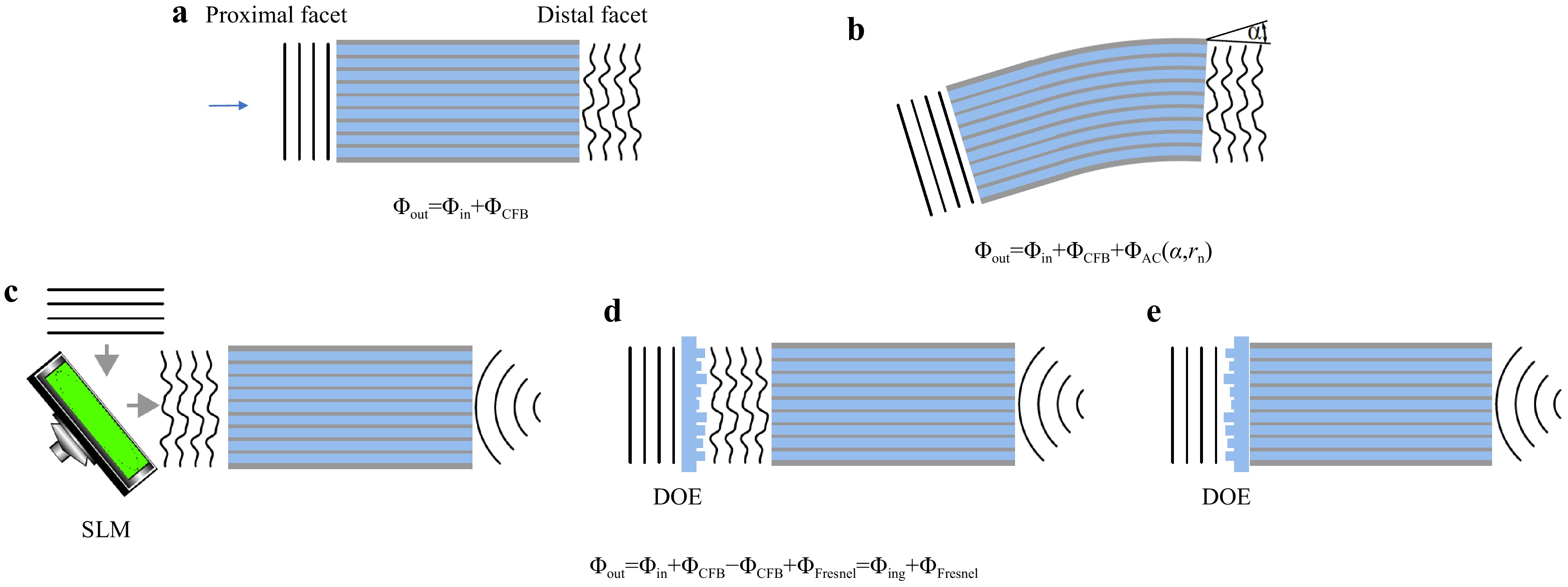
Fig. 1
a Each fiber core exhibits a random phase delay, which adds to the in-coupled wavefront and results in a high spatial frequency disturbance at the fiber output. b Additionally, bending the fiber adds a global tilt to the transmitted wavefront, according to the optical memory effect. c Conventionally, phase distortions are compensated using spatial light modulators for dynamic digital optical phase conjugation (DOPC). Focusing at the distal fiber side is performed by adding the phase structure of a Fresnel lens on the SLM at the proximal fiber side. d The DOE provides focusing and phase conjugation assuming static aberration of the CFB and is placed in front of the proximal fiber facet. e Printed DOE on the proximal fiber facet for aberration correction and focusing. -
Extending the above hypothesis to a commercial CFB with a length-independent core arrangement and several tens of thousands of cores means that bending only induces a radius-dependent tilt in the transmitted wavefront, as shown in Fig. 1b. This results in a lateral shift of the acquired image, which can often be tolerated or corrected if the tilt is measured, either actively by correcting the in-coupled beam or with post-processing. The total phase distortion can be written as
$$ \Delta \Phi = \Delta \Phi_{DC} + \Delta \Phi_{AC}(\alpha,r_n) $$ (1) where
$ \Delta \Phi_{DC} $ denotes the phase distortions for each fiber core due to manufacturing tolerances, which are static, and$ \Delta \Phi_{AC}(\alpha,r_n) $ denotes the phase distortions due to bending by the angle$ \alpha $ and the distance of a core to the neutral axis$ r_n $ , which are dynamic. To verify this assumption, the bending-induced phase distortion was measured holographically using a commercial CFB (Sumita, HDIG, 40 cm). The setup is illustrated in Fig. 2a. A 473 nm CW laser was employed. The CFB was illuminated with a collimated beam from the distal side via beamsplitters BS1 and BS2, single-mode fiber (SMF1), Mirror M1, BS3, and the microscope objective MO2 (20x, NA = 0.40). The transmitted light was imaged onto the CMOS Camera CAM1 (IDS, UI-3482LE, 4.92 MP) via MO1 (10x, NA = 0.25) and lens L3 ($ f = $ 175 mm). The reference beam was generated via SMF2, M2, and BS4. Off-axis holography was employed. The fiber was bent in increments of 1°. The phase difference of consecutive holograms was evaluated to calculate the bending angle-dependent phase difference$ \Delta \Phi_{AC}(\Delta \alpha,r_n) $ . The tilt angle$ \gamma $ was calculated by linearly interpolating the low-pass filtered phase difference of consecutive measurements. A linear dependency of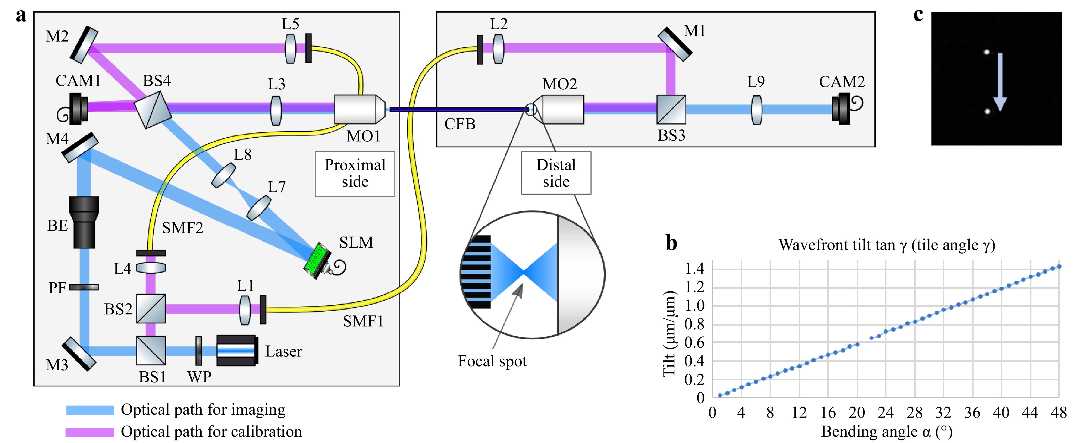
Fig. 2
a Setup for characterizing bending dependent phase deviations of the CFB. Left: Proximal side with instrumentation. Right: Distal side for application. CAM1 is used for the holographic measurement of the phase distortion of the CFB. CAM2 is used to characterize the far-field intensity distribution. b Measured bending angle$ \alpha $ $ \gamma $ $$ \tan \gamma = \frac{\Delta \Phi_{AC} / 2\pi}{r_n / \lambda} = n\cdot \alpha $$ (2) results, as shown in Fig. 2b, which verifies the underlying hypothesis. To test the effect on the far field of the CFB in a lensless imaging configuration, the fiber was illuminated from the proximal side. The employed beam path encompasses BS1, M3, beam expander BE (5x), M4, SLM (Holoeye, Pluto-2), L7 and L8 (collimation lenses), BS4, L3, and MO1. The SLM was used for DOPC of
$ \Delta \Phi_{DC} $ . The SLM was employed in an off-axis setup to suppress surface reflexes and allow for binary amplitude modulation34, 35. The iris diaphragm was used to filter the higher diffraction orders of the SLM. Additionally, a Fresnel lens ($ f = 300\;{\text{µm}} $ ) was coded onto the SLM to achieve a focus point on the distal fiber side. The fiber was bent again, and the lateral shift in the focus position was tracked by CAM2. A lateral focus shift of 4.7 µm/° was observed, confirming previous observations. An example image of two laterally shifted foci is shown in Fig. 2c.The experiments demonstrate that a static phase mask is sufficient for compensating for high-frequency phase aberrations, and that fiber bending only induces low spatial frequency aberrations. These aberrations result mainly in a focus shift and can be compensated numerically in post-processing or by galvo scanners in real time. 3D 2-photon polymerization has previously been used for printing DOE36−39. To demonstrate the capability of 3D 2-photon polymerization for optical phase conjugation in the context of fiber bundle-based endoscopy, two DOEs were designed and printed on a glass substrate using a commercial 3D printer (Photonic Professional GT, Nanoscribe GmbH).
DOE1 is a Fresnel lens with
$ f = 300\;{\text{ µm}} $ . DOE2 is the same Fresnel lens plus the conjugated phase of the CFB. The phase patterns are shown in Fig. 3a, g. Both DOEs were characterized using the setup shown in Fig. 2 without the CFB. The deviations between the designs and measurements are shown in Fig. 3c−e and Fig. 3i−k, respectively. Multiple error sources become apparent. The field of view for printing was restricted to patches of 100 µm × 100 µm. To cover a larger area, several patches were stitched. A tilt of the individual patches, as well as a phase jump at the boundary of two patches, is apparent, as seen in Fig. 3c, i. Owing to a restricted axial resolution, the height was quantized into three steps, as shown in Fig. 3d, j. Furthermore, a systematic deviation is visible in Fig. 3d, j, where it can be seen that the printed step height equals approximately half the designed step height. This is probably due to operation or design errors. Finally, Gaussian distributed random errors can be seen in Fig. 3d, j, which can result from the printing as well as electronic noise and aberrations in the holographic measurement process. In total, the phase deviations exhibit comparable standard deviations of$ \sigma_{\varphi,DOE1} = 0.89 $ for the Fresnel lens and$ \sigma_{\varphi,DOE2} = 1.04 $ for the phase compensation DOE, as shown in Fig. 3e, k. Nevertheless, a sharp focus with a full width at half maximum (FWHM) = 1.15 µm is achieved in the focal plane of DOE1. The peak-to-background ratio (PBR), which is defined as the ratio of the mean focus intensity to the mean intensity outside the focus, reaches$ \text{PBR} = 308 $ , as seen in Fig. 3f. Higher diffraction orders are apparent, which result from sub-sampling of the desired wavefront. This limits the field of view to 30 µm, according to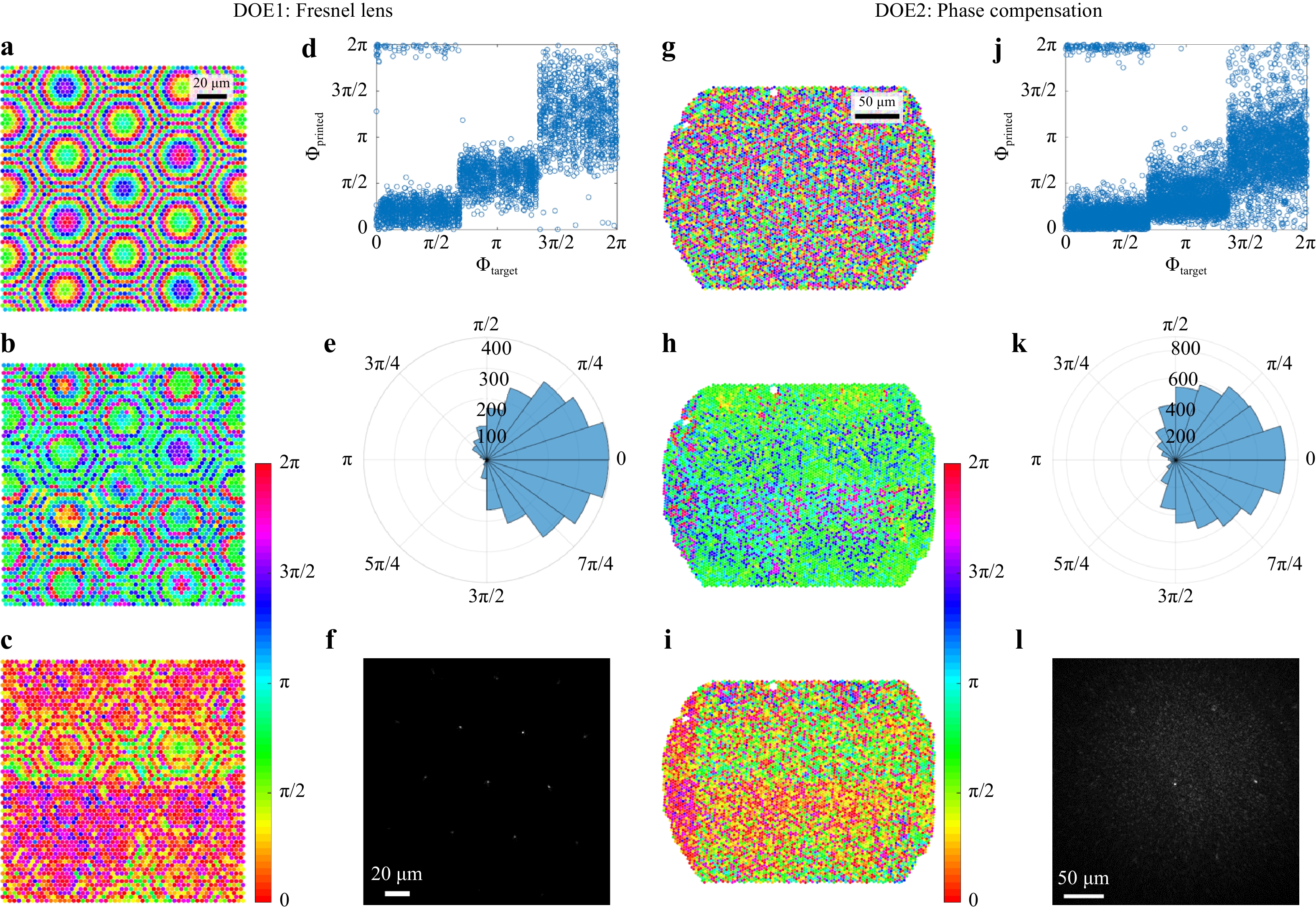
Fig. 3
Left: Fresnel lens. a Design, b Holographic measurement, c−e Deviation, f Far field in the focal plane. Right: Mask for phase compensation of CFB. g Design, h Holographic measurement, i−k Deviation, l Far field in the focal plane.$$ \text{FOV} = \frac{\lambda f}{k_\text{c}\sin{\pi/3}} $$ (3) where
$ k_\text{c} = 3\;{\rm{\mu m}} $ denotes the pitch between printed elements, and$ \sin{\pi/3} $ results from the hexagonal arrangement.While the focus quality of DOE1 was characterized without CFB, the CFB was introduced into the setup again to test DOE2. DOE2 was positioned in front of the proximal side of the CFB, as shown in Fig. 4, and a focus without distal optics was achieved through the CFB. The focal plane is depicted in Fig. 3l (FOV = 60 µm). The higher diffraction orders result from the periodic fiber core arrangement and can be suppressed by aperiodic CFBs40, 41. A focal diameter of
$ FWHM = 1.25\;{\rm{\mu m}} $ , which is limited by the numerical aperture of the fiber cores27, and a$ PBR = 25 $ limited by the DOE quality are achieved. This result is considerably worse than that of DOE1. We assume that this is mainly due to misalignment of the CFB and DOE, which could be solved by printing onto the CFB directly, as well as by depolarization effects in the CFB, because we found that the depolarized light exhibits a different random phase distortion and increases the speckled background. Nevertheless, the DOE2-CFB combination was used for 2D raster scanning microscopy of a USAF test chart (Group 7, Element 6). Therefore, the SLM shown in Fig. 2a was replaced by a 2D galvanometer scanner with scan rates up to 1 kHz. The results are shown in Fig. 4 (right). The achieved resolution of 1.25 µm results from the focal diameter. The comparably low contrast is due to the decreased PBR.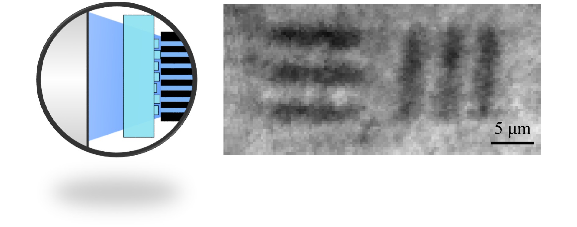
Fig. 4
Left: Scheme of DOE2 in front of the CFB at the proximal side. Right: Transmission raster scan of a USAF 1951 test chart (Group 7, Element 6). -
A different approach to employing 3D printing techniques for 3D endomicroscopy is to code the 3D information using a random but known phase object. This enables single-shot 3D imaging. Recently, imaging through diffuse scattering media by speckle correlation techniques, exploiting the memory effect, has been presented42−48. As in standard optical systems such as microscopes, the far field of a diffuser can be described by the point spread function (
$ PSF $ ). Under the assumption of shift-invariance of the$ PSF $ , meaning an infinite memory effect, the speckle pattern on a detector$ I(r_D) $ of a two-dimensional object$ O(z,r) $ at distance$ z_O $ results from the convolution of the object and the$ PSF $ :$$ I(r_D) = O(r_O)*(PSF) $$ (4) With a known
$ PSF $ , the object can be reconstructed by the cross-correlation$$ I(r_D) \otimes PSF = O(r_O)*(PSF \otimes PSF) \approx O(r_O) $$ (5) under the assumption that the
$ PSF $ is uncorrelated. Furthermore, it has been shown that neural networks can be used for object reconstruction through diffuse scattering media even in the absence of a strong memory effect49−53 and that CFBs enable the transfer of speckle patterns54. To circumvent the remaining issues, with the phase-conjugation-based endoscope, we employed a random phase object in the far field of a CFB. This codes the 3D object information in a 2D intensity pattern, which can be transferred through the CFB without regard for bending-induced phase distortions. The speckle pattern of a 3D object is then reconstructed using a pretrained convolutional neural network (CNN). A schematic of this technique is shown in Fig. 5a.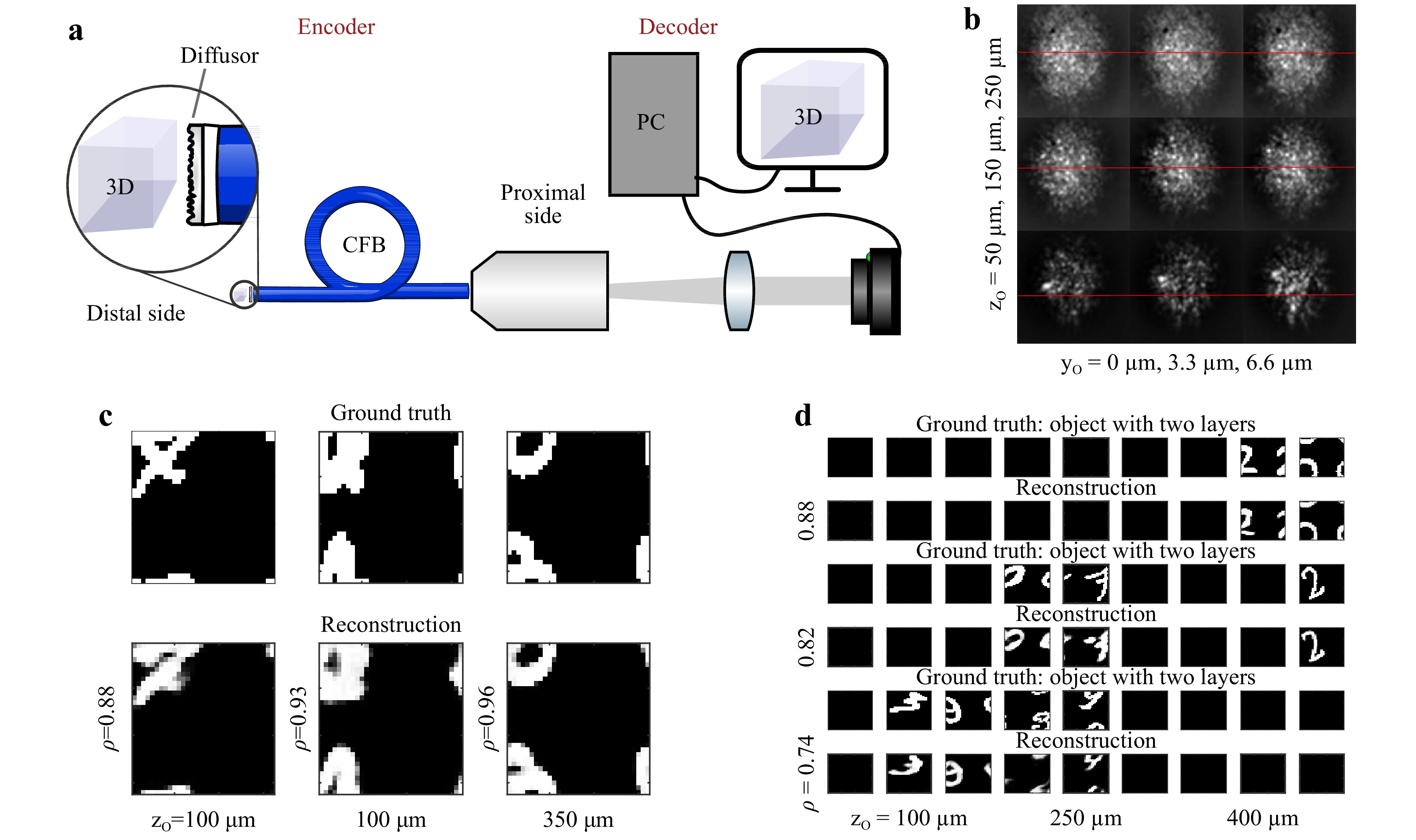
Fig. 5
a Scheme and principle of a diffuser endoscope. The diffuser at the distal side codes the 3D object information into a 2D speckle pattern, which is transferred through the CFB to the proximal side. The 3D information is recovered in real time using a neural network. b PSF for varying distances (top to bottom) and vertical positions (left to right). Horizontal lines indicate the vertical shift of the PSF. c Example reconstructions of 2D objects at a random and unknown distance. d Example reconstructions of multilayered 3D objects at a random and unknown distance.To generate sufficient data for network training, validation, and testing, we captured the PSF of
$ 32 \;\times\; $ $ 32 \;\times\; 9 $ point sources spanning a volume of$ 100\; \times\; 100\; \times\; $ $ 400 $ µm3, sequentially, using a 3-axis scanning system. The focus was imaged in front of the random phase object. We employed a commercial diffuser (Thorlabs DG10-120-A). The diffuser was placed 500 µm in front of a CFB (Fujikura, FIGH-50-1100N, 50k cores, length: 10 cm) with the diffuse plane facing the fiber facet. The transmitted light was imaged using a CMOS camera (uEye, 8 bit). The images were truncated to a square encompassing approximately 90% of the CFB area and resized to$ 64\; \times\; 64 $ pixels. Subsequently, virtual objects were generated using the MNIST database of handwritten digits. The images were rescaled to$ 32\; \times\; 32 $ pixels and shifted randomly in the x- and y-directions for data augmentation. Under the assumption of incoherent radiation, speckle patterns of 3D objects, resolved with$ 32\; \times\; 32\; \times\; 9 $ voxels, were then generated by multiplying the objects with the recorded PSFs. The resulting speckle images were normalized to eight bits.A common task in endoscopy is the imaging of an object with a constant but unknown distance55. Therefore, the network was tested on 1,000 2D objects for each object plane. On average, the network was attributing more than 98% of the total intensity to the correct object plane, independent of the object distance. Furthermore, we found that in 100% of cases, the majority of the intensity was attributed to the correct plane. This means that the correct distance of the 2D objects was always detected. The reconstruction quality was assessed using the correlation coefficient
$ \rho $ between the reconstruction and the object in the identified plane. The reconstruction quality appears to be almost independent of the object distance, as shown in Fig. 6 (top). For qualitative comparison, three examples of the reconstruction are shown in Fig. 5c. The chosen examples represent reconstructions with differing quality$ \rho = 0.88 $ (10%-quantil),$ \rho = 0.93 $ (50%-quantil), and$ \rho = 0.96 $ (90%-quantil). It can be seen that, even in the worst case, the object is still clearly recognizable. To test robustness, noise (uniform distribution, range [−2, 2]) was added to the speckle images (range [0, 255]) before reconstruction. While there is a slight reduction in the resulting quality, the reconstructed objects are still recognizable.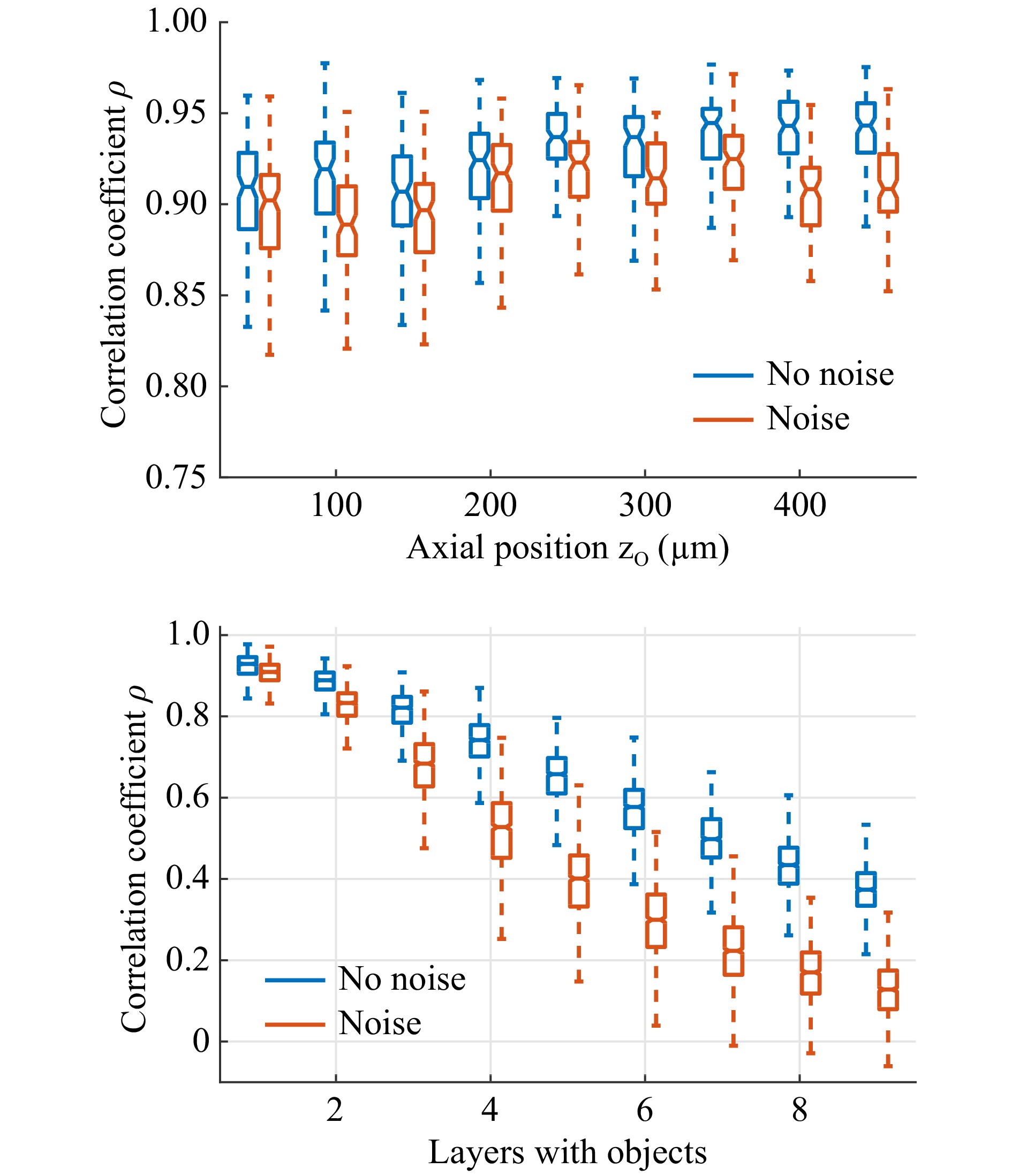
Fig. 6
Top: Reconstruction of single-layered objects. Correlation coefficient$ \rho $ $ \rho $ To test the CNN on the more generalized problem of 3D objects with varying object distances, 1000 objects and their corresponding speckle patterns with one to nine filled planes were generated. The same CNN that was trained on single- and double-layered objects was employed for object recovery. Fig. 6 (bottom) shows the achieved correlation depending on the number of filled planes. It can be seen that the reconstruction quality deteriorates with increasing object complexity. The deterioration increases with the addition of noise. We assume that this results from a decrease in speckle contrast
$ C \propto n_p^{1/2} $ with an increasing number of independent point sources$ n_p $ forming the 3D object. This results in a reduction in the signal to noise ratio from 20 dB for objects with a single object layer to 7 dB for objects with nine layers. Nevertheless, for objects with two and three filled layers, the reconstructions are still clearly recognizable. Fig. 5d shows three example reconstructions for objects with two to four filled layers. The examples shown represent reconstructions with the median of the achieved correlation coefficients. -
We investigated compact DOE-based lensless fiber endoscopes with ultra-thin footprints for 3D imaging. Two techniques, DOE-grating and DOE-diffuser-based endoscopy, were introduced. Both enable paradigm-shifting applications with minimal invasive access in biomedicine.
Lensless endoscope I: Lithography has been used for many years in the manufacturing of simple DOEs, such as gratings and Fresnel lenses. We demonstrate that DOE made by 2-photon lithography can be used to conjugate arbitrary phase distortions in CFBs. Pre-coding the transmitted light, for instance with a Fresnel lens, can be performed with the same DOE. Placing the DOE on the proximal fiber facet enables lensless raster scanning endomicroscopy with a lateral resolution of approximately 1 µm. As an advantage, this can result in a less expensive, simpler, and more robust setup compared to digital optical phase conjugation using SLMs. Additionally, using 3D printed DOE in the transmission is potentially more light-efficient than a reflective liquid crystal on silicon SLM, which is normally used for DOPC. Currently, the main issues for image quality are DOE quality and positioning, which result in reduced image contrast. Thus, great potential for image quality, as well as robustness, arises from integrating the DOE directly onto the CFB. Further advances can be made in combination with advanced fiber design, for instance, using an aperiodic core arrangement to suppress higher diffraction orders and bending insensitive fibers. The resulting fiber is phase-containing, meaning that arbitrary light fields can be generated for further applications, such as optogenetic cell stimulation or fiber optical tweezing56, 57. As a disadvantage in endomicroscopy, the volume information is time-coded, limiting the temporal resolution.
Lensless endoscope II: An unstructured random DOE (diffuser) can be realized by 3D printing, for example, onto a glass plate or standard optical diffusers. Placed in the far field of a CFB, they code the 3D object information in a 2D speckle pattern that can be transferred through the CFB without considering phase scrambling. The 3D object can then be reconstructed using neural networks. In contrast to other ultrathin 3D endoscopes, imaging is performed in a single shot. In combination with using neural networks for object reconstruction, this can enable real-time 3D imaging, for instance, in time-resolved GFP-based or calcium imaging in optogenetics or auto-fluorescence imaging in cancer diagnostics. In contrast to structured DOEs for phase conjugation, the DOE quality is insignificant because the exact transmission properties are learned by signal processing. Nevertheless, the use of reproducible DOEs offers great potential because the time-consuming training process can be reduced. However, the speckle contrast decreases with an increase in the number of scattering sources. Thus, this technique requires sparse objects such as stained tissues. Furthermore, reconstruction of tissue samples requires corresponding training data, which could be achieved by displaying microscope recordings to the system using a micro-projector.
-
DOE quality: When using the CFB as a phased array, the achievable image contrast in raster scanning depends on the peak-to-background ratio (
$ PBR $ ) of the generated focus, also called the enhancement factor. The$ PBR $ describes the focus intensity$ I_f $ in relation to the mean background intensity$ I_b $ ,$$ PBR = \frac{I_f}{I_b} = \frac{\pi}{4}(N-1)+1\approx \frac{\pi}{4}N $$ (6) where
$ N $ denotes the number of independent phasors or fiber cores58. However, Eq. 6 only holds under the assumption of ideal phasors with equal amplitude. In reality, phase errors occur, as seen in Fig. 3. Quantization errors$ \Delta \varphi_Q $ result from the DOE design process. The DOE was designed to contain three steps that are equally spaced over$ \pm \pi $ , yielding a maximum quantization error of$ \Delta \varphi_{Q,max} \approx \pm \pi/3 $ results. Furthermore, a systematic deviation$ \Delta \varphi_S $ is apparent between the designed height and the measured phase. This can be caused by unequal refractive index or non-optimal design of the printed pillars, as well as misalignment of the printer. The maximum systematic deviation is$ \Delta \varphi_{S,max} \approx \pm \pi/2 $ . Finally, random errors$ \Delta \varphi_R $ occur with a standard deviation of$ \sigma_{\varphi,R}\approx 0.5 $ , which can result from the printing, as well as electronic noise and aberrations, in the holographic measurement process. Assuming equal distributions for$ \Delta \varphi_Q $ and$ \Delta \varphi_S $ and independence, we can summarize all three contributions to the total phase uncertainty:$$ \begin{split} \sigma_{\varphi \text{DOE2}} & = ( {\Delta \varphi_{Q,max}^2}/3+ {\Delta \varphi_{S,max}^2}/3+ \sigma_{\varphi,R}^2)^{1/2}\\ & = (0.37+0.41+0.25)^{1/2} \approx 1.04 \end{split} $$ $ \sigma_{\varphi} $ is dominated by$ \sigma_{\varphi,Q} $ and$ \sigma_{\varphi,S} $ . To estimate the effect of phase noise on the$ PBR $ , a Monte Carlo simulation was performed assuming normal distributed phase deviations. The relation$ PBR_\text{noise} = PBR\cdot exp(-\sigma_{\varphi}^2) = {\pi}/{4}N\cdot e^{-\sigma_{\varphi}^2} $ was found. This is in good agreement with the experimental data for DOE1, where$ PBR_\text{DOE1} = 308 $ was measured and$ PBR_\text{DOE1}(N = 1500; \sigma_{\varphi} = 0.9) = 550 $ results. The comparably worse performance of DOE2 in combination with the CFB is attributed to misalignment and the free-space propagation between the DOE and CFB and emphasizes the requirement to print the DOE directly onto the CFB.Printing process: The DOEs were designed from circular pillars with a diameter of 2.8 µm and lateral distance of 3.0 µm to match the fiber core dimensions. The achieved phase delay results from the pillar height
$ h $ and photosensitive polymer refractive index$ n_p = 1.535 $ to$$ h = \cfrac{\Delta \Phi_{DC}}{2\pi}\cdot\cfrac{\lambda}{n_p-1} $$ (7) yielding a maximum height for
$ 2\pi $ modulation of$ h_\text{max} = 884 \;{\rm{nm}} $ . A base layer was first printed on the substrate to guarantee full-field adhesion. The DOEs were realized using a commercial 3D printer (Photonic Professional GT, Nanoscribe GmbH).Network architecture and training: The neural network employed for 3D object reconstruction consists of nine independent convolutional neural networks (CNNs) with identical architecture. The number of CNNs corresponds to the number of object planes, and each CNN reconstructs the information of one associated object plane. We found that this architecture offers an improved training speed compared to 3D-CNN without a loss in performance. The architecture of a single CNN, which is derived from U-Net59, is depicted in Fig. 7. The network consists of four encoder stages, with an image input size of
$ 64\;\times\;64 $ pixels. Since the object plane was restricted to$ 32\;\times\;32 $ pixels, only three decoder stages are employed. The last encoder stage uses two dropout layers to inhibit overfitting. In total, the CNN consists of 52 hidden layers. For training, each CNN was presented with the same 90,000 speckle patterns resulting from single- and double-layered objects to learn to reconstruct images in the corresponding object plane and reject information from non-corresponding object planes.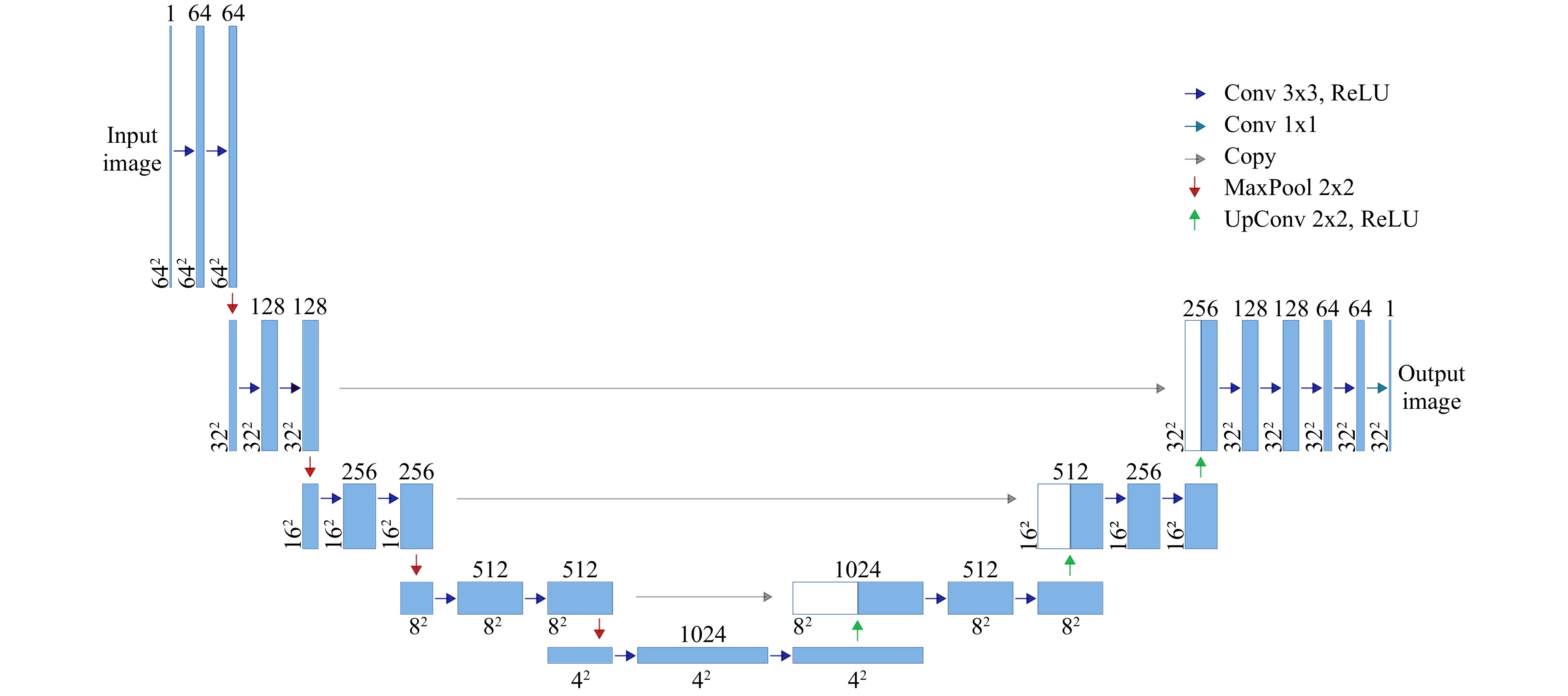
Fig. 7
Scheme of the Convolutional Neural Network (CNN) consisting of four encoder stages and three decoder stages. The last encoder stage uses two dropout layers to reduce overfitting. In total, nine individually trained CNNs were employed, with each one reconstructing one associated object plane. -
This work was supported by the German Research Foundation (DFG) under grants (CZ 55/47-1) and (CZ 55/48-1). We want to thank Heifeng Xu, Mariana Medina-Sánchez, and Oliver G. Schmidt from the Institute for Integrative Nanosciences, Leibniz IFW Dresden, for manufacturing the DOEs.
Ultra-thin 3D lensless fiber endoscopy using diffractive optical elements and deep neural networks
-
Robert Kuschmierz1, 2, *, ,
 ,
, - Elias Scharf1, 2,
- David F. Ortegón-González1,
- Tom Glosemeyer1,
-
Jürgen W. Czarske1, 2, 3, 4, *, ,
- Light: Advanced Manufacturing 2, Article number: 30 (2021)
- Received: 09 June 2021
- Revised: 12 November 2021
- Accepted: 20 November 2021 Published online: 06 December 2021
doi: https://doi.org/10.37188/lam.2021.030
Abstract: Minimally invasive endoscopes are indispensable in biomedicine. Coherent fiber bundles (CFBs) enable ultrathin lensless endoscopes. However, the propagation of light through a CFB suffers from phase distortions and aberrations that can cause images to be scrambled. The correction of such aberrations has been demonstrated using various techniques for wavefront control, especially using spatial light modulators (SLMs). This study investigates a novel aberration correction without SLM for the creation of an efficient and compact system. The memory effect of CFBs enables a paradigm shift in the use of static diffractive optical elements (DOEs) instead of dynamic modulation with SLM. We introduce DOEs produced by 2-photon polymerization lithography for phase conjugation on a CFB for focusing, raster scanning, and imaging. Furthermore, a DOE with random patterns is used to encode the three-dimensional (3D) object information in a 2D speckle pattern that propagates along the ultra-thin CFB. Neural networks decode the speckles to retrieve the 3D object information using single-shot imaging. Both DOE methods have compact low-cost concepts in common, and both pave the way for minimally invasive 3D endomicroscopy with benefits for optical imaging in biomedicine.
Research Summary
Diffractive optical elements: DOEs and Neural Networks enable miniaturized 3D endoscopes
3D printed diffractive optical elements (DOEs) with sub-micron feature size enable sub-millimeter sized 3D endoscopes. Miniaturized, flexible endoscopes rely on coherent fiber bundles (CFBs), which relay images from inside the body to a camera for 2D imaging. However, the propagation of light through a CFB suffers from random distortions that hinder 3D imaging without complex and bulky setups. Dr. Kuschmierz, Prof. Czarske and colleagues from TU-Dresden, Germany report on DOEs produced by 2-photon polymerization lithography to compensate these distortions to enable 3D imaging without any lenses on the CFB. Furthermore, a DOE with random patterns can be used in conjunction with neural networks to circumvent the distortions altogether for single shot 3D imaging. Both methods enable compact, low cost 3D systems with resolution of around 1 µm and diameters below 0.5 mm for biomedical applications.


Rights and permissions
Open Access This article is licensed under a Creative Commons Attribution 4.0 International License, which permits use, sharing, adaptation, distribution and reproduction in any medium or format, as long as you give appropriate credit to the original author(s) and the source, provide a link to the Creative Commons license, and indicate if changes were made. The images or other third party material in this article are included in the article′s Creative Commons license, unless indicated otherwise in a credit line to the material. If material is not included in the article′s Creative Commons license and your intended use is not permitted by statutory regulation or exceeds the permitted use, you will need to obtain permission directly from the copyright holder. To view a copy of this license, visit http://creativecommons.org/licenses/by/4.0/.

 DownLoad: