


-
Advanced manufacturing is associated closely with precise measurements. Improving product quality is indispensable to the development of the manufacturing industry, and the key aspect is precise measurement, which significantly improves continuous precise control and manufacturing. Meanwhile, equipment automation is crucial in advanced manufacturing and requires precise and effective real-time monitoring to provide feedback and guide the manufacturing process toward improving production efficiency and product quality. Moreover, the real-time monitoring of facilities, particularly large facilities (such as rail transit systems, large bridges, and buildings), can provide information regarding their surrounding environment and allow their health conditions to be assessed, which is essential for establishing the current concept of smart cities based on the Internet of Things. As a precise real-time monitoring technique, distributed fibre-optic sensing (DFOS) systems, which require long-distance simultaneous measurements along a sensing fibre1-3, are in high demand for various industrial applications. Three types of scattering phenomena in optical fibres are applied in DFOS systems to measure various physical quantities, i.e. Rayleigh backscattering (RBS), Brillouin scattering (BS), and Raman scattering (RS)4,5. RBS is a type of elastic scattering caused by random fluctuations in the refractive index of a fibre. The measurement of static parameters such as strain and temperature based on RBS lightwaves generally requires a wide-range optical frequency sweep of the lightwave, which imposes a high requirement on the optical source6,7. By contrast, a technique using RBS lightwaves known as phase-sensitive optical time-domain reflectometry (φ-OTDR), which is used to measure dynamic parameters such as vibration, does not require an optical frequency sweep; therefore, RBS light waves are particularly suitable for vibration measurement8,9. Unlike RBS, BS is a type of inelastic scattering generated by the interaction between an incident lightwave and acoustic phonons. Because the interaction is related to strain and temperature, the values of the two parameters can be measured10. Compared with strain and temperature sensing methods using an RBS lightwave, Brillouin sensing systems are advantageous in terms of sensitivity and impose low requirements for the light source sweep range; however, they are not suitable for vibration measurement owing to the time cost of the frequency-sweeping process. By contrast, RS is another type of inelastic scattering generated by the interaction between an incident lightwave and optical phonons. It can be used in Raman optical time-domain reflectometry (ROTDR)11-13 to measure the distributed temperature without being disturbed by strain as RS is only temperature sensitive. For the DFOS system, different types of sensing fibres can be used, such as single-mode fibres (SMFs), polarisation-maintaining fibres, multimode fibres, few-mode fibres, and multicore fibres14-18. However, the most economical and effective scheme is to use the standard SMF, which is typically pre-installed in most industrial applications.
As DFOS systems using different backscattering phenomena have different sensitivities to different measurands, researchers have proposed various hybrid systems to achieve multiparameter measurements. For example, RBS and BS lightwaves were combined as the base of a hybrid system19-29. In these systems, Brillouin optical time domain reflectometry (BOTDR) or Brillouin optical time domain analysis (BOTDA) is used to measure temperature and static strains, whereas φ-OTDR is used to measure vibration. However, for both RBS and BS lightwaves, the cross-sensitivity of strain and temperature is a severe problem that hinders their practical use in many industrial applications. However, RS lightwaves are only temperature sensitive, and ROTDR is an effective tool for providing information regarding the distributed temperature. Therefore, by integrating ROTDR to the hybrid system, the cross-sensitivity of strain and temperature can be overcome. However, combining these three techniques is complex.
Herein, we propose a hybrid DFOS system that combines systems using three different scattered lightwaves via a single-end scheme. Two successive pulses are launched into the system to realise Brillouin amplification of the RBS lightwave21: a Rayleigh probe pulse of φ-OTDR for vibration measurement, followed by a Brillouin pump pulse of a single-end BOTDA system for strain/temperature measurement. The RBS lightwave of the probe pulse serves as a continuous probe wave for the single-end BOTDA. For ROTDR, a wavelength division multiplexer (WDM) is used to obtain Stokes and anti-Stokes RS lightwaves. Because a pulse pair is used in the system and the frequency deviation is not sufficiently large to be distinguished in the ROTDR system, a 3-bit pulse coding method is employed to demodulate the RS lightwave of the two pulses.
Compared with a system that uses the same pulse to realise simultaneous sensing, the proposed system improves the measurement accuracy of the Brillouin system because it uses BOTDA and not BOTDR. Moreover, for the proposed system, only the RBS must be received to demodulate the information of φ-OTDR and BOTDA systems, which avoids the use of a large-bandwidth receiver or additional receivers to receive the BS. The dynamic range of the Brillouin system is not limited by the bandwidth of the receiver or the sampling rate, which simplifies the requirements of the receiver significantly. Using this hybrid scheme, a simultaneous measurement of multiple parameters is realised and the measurement accuracy achieved is 21.36 με (strain), 0.50 °C (temperature), and the order of 10 pε/√Hz@1 kHz (vibration).
-
The conceptual design of the hybrid system is shown in Fig. 1. Fig. 1a shows the overall scheme with three pulse pairs used for measuring the parameters along the fibre under test (FUT). Each pulse pair, which comprised a Rayleigh probe pulse (orange) and Brillouin pump pulse (blue), was used to measure the dynamic and static parameters corresponding to φ-OTDR and single-end BOTDA. Three pulse pairs were employed as a coding technique to demodulate the ROTDR because separating the RS lightwaves of the two pulses in each pulse pair was extremely difficult in time domain. A WDM was used to guide lightwaves of three different wavelengths to different channels (1550 nm for φ-OTDR and BOTDA; 1450 and 1663 nm for ROTDR).
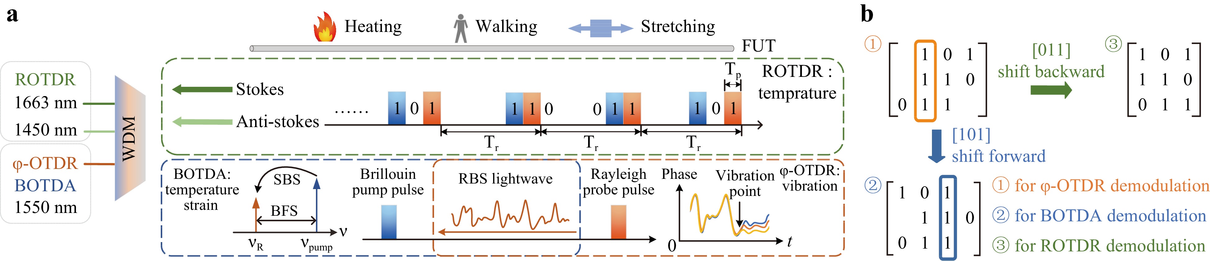
Fig. 1 Conceptual design of hybrid system. a Coded pulse pairs for measuring FUT, and illustrative description of three-channel scattering signals for detection. b Simplex pulse coding scheme to separate Raman signal of pulse pairs.
The detailed principle of φ-OTDR and the single-end BOTDA system using a 1550 nm-channel is illustrated in Fig. 1a. In conventional two-end BOTDA systems, a pump pulse and a continuous probe lightwave are injected into the sensing fibre from opposite ends, and the probe lightwave can be amplified by a pump pulse via stimulated Brillouin scattering (SBS). The proposed single-end BOTDA system uses the RBS lightwave of the Rayleigh probe as a continuous probe wave in BOTDA systems, whereas the pump pulse serves as a pump source to amplify the RBS probe28,29. The spatial resolution of the BOTDA subsystem, which is unrelated to the Rayleigh probe pulse, was determined based on the pump pulse. The optical frequency of the Brillouin pump pulse was upshifted around the Brillouin frequency shift (BFS) compared with that of the Rayleigh probe pulse. Thus, when the pump pulse coincides with the RBS lightwave transmitted in the opposite direction, energy is transferred from the high-frequency lightwave (pump pulse) to the low-frequency lightwave (RBS lightwave of the probe pulse) owing to the SBS, as the frequency difference conforms to the BFS of the fibre (~ 11 GHz in a standard single-mode fibre). This process can be described by the following three coupled-wave equations30:
$$ \begin{split}& \frac{{\partial {E_B}(z,t)}}{{\partial z}} + \frac{1}{\upsilon }\frac{{\partial {E_B}(z,t)}}{{\partial t}} = j\frac{1}{2}{g_2}(z){E_R}(z,t)Q(z,t) \\& \frac{{\partial {E_R}(z,t)}}{{\partial z}} - \frac{1}{\upsilon }\frac{{\partial {E_R}(z,t)}}{{\partial t}} = - j\frac{1}{2}{g_2}(z){E_R}(z,t){Q^ * }(z,t) \\& \frac{{\partial Q(z,t)}}{{\partial t}} + \Gamma Q(z,t) = j{g_1}(z){E_B}(z,t)E_R^ * (z,t) \end{split} $$ (1) where EB and ER are the electric field complex amplitudes of the Brillouin pump pulse and RBS lightwave respectively; υ is the group velocity of the sensing fibre; g1 and g2 are Brillouin gain coefficients, which are related to the fibre type and optical wavelength, respectively; and $ \Gamma = 1/2{\tau _p} + j(\omega _B^2 - {\omega ^2})/2\omega $, $ {\tau }_{p} $ is the lifetime of phonon, $ {\omega }_{B} $ is the BFS of sensing fiber and $ \mathrm{\omega } $ is the frequency difference between Brillouin pump pulse and RBS lightwave of the probe pulse; and j is the imaginary unit. Therefore, by changing the frequency difference between the Brillouin pump pulse and Rayleigh probe pulse, the frequency gain spectrum distributed along the fibre can be obtained.
The BFS along the fibre is linearly related to the strain and temperature, as shown in Equation 2, where c11 and c12 are the strain and temperature coefficients of the SBS, respectively.
$$ \Delta {\nu _B} = {c_{11}}\Delta \varepsilon + {c_{12}}\Delta T $$ (2) The BFS corresponds to the peak of the Brillouin gain spectrum (BGS). By changing the frequency difference between the Brillouin pump pulse and the RBS probe wave around the BFS, we obtained the BGS along the FUT. The RBS probe wave was received for the vibration measurement, and the phase was extracted to demodulate the vibration along the FUT. Although the SBS process involves a phase gain spectrum in addition to an amplitude gain, because the BOTDA system is used for measuring static parameters, the sweeping process of the BOTDA and the effect of the SBS on the phase gain of the RBS probe wave can be eliminated by the differential process in both the time and spatial domains when conducting vibration demodulation. The spatial resolution of the φ-OTDR subsystem is determined by the width of the Rayleigh probe pulse, which is unrelated to the Brillouin pump pulse that is inherently filtered out by coherent detection.
For ROTDR, the Stokes/anti-Stokes scattering lightwave is obtained using two avalanche photodiodes (APDs) at 1450 nm and 1663 nm channels. If the intensity of the pulses and the attenuation coefficient along the fibre are regarded as constant, then the intensities of the Stokes and anti-Stokes lightwaves depend only on temperature. The Stokes/anti-Stokes lightwave power ratio $F(T)$ must be calculated to eliminate the effect of optical power variations from the optical source. To eliminate the effect of fibre attenuation, ${T_0}$ was set as a reference temperature. Meanwhile, the ratio of the measured temperature to the reference temperature $R(T) = F(T)/F({T_0})$ is linearly related to the temperature change. Therefore, the temperature change can be calculated using Eq. 3.
$$ \Delta R(T) = {c_{22}}\Delta T $$ (3) where ΔT is the temperature change and c22 is the temperature coefficient in ROTDR31.
Separating the RS lightwaves of the two pulses in each pulse pair is in the frequency domain is extremely difficult because the frequency difference between the two pulses (~11 GHz) is three orders of magnitude smaller than the Raman frequency shift (~13 THz), and the RS gain bandwidth is greater than 5 THz32, which is much larger than the sweep range of the Brillouin pump pulse (typically a few hundred megahertz). To maintain the same spatial resolution of the ROTDR subsystem as the scheme using a single pulse, we designed a simplex pulse coding scheme to separate the Raman signal of the pulse pairs, as shown in Fig. 1b.
Because the pulse width and interval between two pulses are adjustable, 3-bit simplex coding can be performed in the time domain. The interval does not affect φ-OTDR. In BOTDA, an increase in the pulse interval only shortens the measurable length at the fibre end because the probe lightwave of BOTDA disappears when the Rayleigh probe pulse travels out of the fibre. This does not affect the measurement results at other positions. Therefore, the pulse coding method introduced for demodulating the ROTDR barely affected the other two measurements. Because the conventional 3-bit simplex code is cyclic and the interval between Rayleigh probe pulses corresponding to the three matrix rows are different, the vibration sampling will feature uneven intervals, which adversely affects Brillouin pump pulses. Therefore, the coding and decoding methods must be designed well to ensure the appropriate φ-OTDR and BOTDA, under the abovementioned pulse-coding scheme.
Several parameters are introduced in this section. As shown in Fig. 1a, the width of every pulse is $ {T_p} $, and the spatial resolution of the three subsystems is $ {T_p} \cdot v/2 $, where v is the speed of the lightwave in the optical fibre. To implement Simplex coding, the width and the interval (for the case of ‘0’) between the two pulses are set to $ {T_p} $, and the interval between adjacent pulse pairs is set to $ {T_r} $. $ {T_r} $ should be larger than $L/2v$ (where L is the fibre length) to realise distributed sensing. To achieve successful decoding using the proposed system, the minimum value of $ {T_r} $ should be $L/2v + {T_p}$.
The Simplex coding and decoding processes are shown in Fig. 1b, where ‘1’ represents pulse and ‘0’ represents a time interval of $ {T_p} $. The first ‘1’ and second ‘1’ are different: the first ‘1’ in each row represents the Rayleigh probe pulse, and the second ‘1’ represents the Brillouin pump pulse. Although the two pulses have the same width, they exhibit a frequency difference of ~11 GHz. They can be regarded as the same in the ROTDR subsystem owing to the large Raman frequency shift and gain bandwidth, but different in φ-OTDR and BOTDA subsystems. Simplex coding is used to separate the Raman scattering of the two pulses to guarantee the spatial resolution of the ROTDR subsystem but does not affect those of the φ-OTDR and BOTDA subsystems. Each row in the matrix represents a pulse pair generated using this code. To ensure that the vibration sampling intervals are equal, the [0 1 1] of the conventional 3-bit Simplex code must be shifted one bit ahead by an interval of $ {T_p} $.
Different demodulation schemes are used for the three measurements. For φ-OTDR, the RBS lightwave corresponding to the three rows can be demodulated directly without decoding. For BOTDA, the Brillouin pump pulses in row [1 0 1] exhibit a lag of one bit relative to those in the other rows. During the demodulation process, after the gain of each RBS lightwave along the fibre is calculated, the gain corresponding to the [1 0 1] row should be shifted forward in the time domain by an interval of the spatial resolution and aligned with the gain obtained from the other two rows to accurately obtain the BGS at each position along the fibre. For ROTDR, after shifting the RS signal in the row [0 1 1] by an interval of the spatial resolution, the conventional 3-bit simplex decoding method can be used to obtain the ROTDR curve for a single pulse.
-
An experiment was performed to verify the feasibility of the hybrid system, and the experimental setup is shown in Fig. 2. A narrow-linewidth laser with a wavelength of 1550 nm (NKT Photonics Koheras Adjustik) was used as the light source. The lightwave from the laser was separated by a 50:50 polarisation-maintaining coupler (PMC), and a Brillouin pump pulse was generated in the first branch. An intensity modulator (Optilab IM-1550-20-A), which was operated in the suppressed carrier mode and driven by a voltage-controlled oscillator (VCO, Analog Devices HMC1164), was used to generate two sidebands. The VCO was driven by an arbitrary function generator (Tektronix AFG3252C) and provided high-speed frequency sweeping for constructing the BGS. The anti-Stokes sideband was filtered using an optical bandpass filter (Santec OTF-970) and amplified using an injection-locking module. Subsequently, this sideband was modulated to become a Brillouin pump pulse using an acousto-optic modulator (AOM1, Gooch & Housego Fibre-Q). A polarisation scrambler (General Photonics PolaRITETM II) was used to eliminate the effect of polarisation mismatch in the SBS process by rapidly changing the polarisation states of the Brillouin pump pulse, and the polarisation effect was eliminated by averaging.
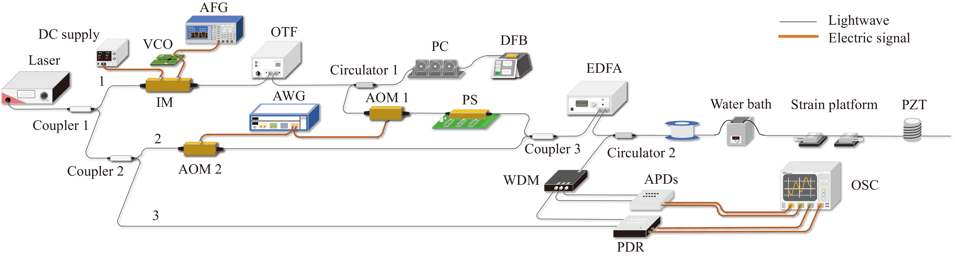
Fig. 2 Experimental setup for verifying the feasibility of the hybrid system. AWG: arbitrary wave generator, IM: intensity modulator, OBPF: optical bandpass filter, PC: polarization controller, AOM: acousto-optic modulator, PS: polarization scrambler, PDR: polarization diversity receiver, WDM: wavelength division multiplexer, BPD: balanced photo-detector, APD: avalanche photodiode.
The second branch was separated by a 50:50 PMC and modulated by another acousto-optic modulator (AOM2, Gooch & Housego Fiber-Q) to generate a Rayleigh probe pulse. The AOMs and VCO were driven and synchronised using an arbitrary waveform generator (Keysight M9502A). The Rayleigh probe and Brillouin pump pulses were combined into a pulse pair using a 50:50 coupler and then amplified using an erbium-doped fibre amplifier (Amonics AEDFA-23-B-FA) before being launched into the FUT via a circulator. A WDM was used to separate the RBS and RS lightwaves of the two pulses, and the Stokes and anti-Stokes RS lightwaves were received by the two APDs. Meanwhile, the RBS lightwave after Brillouin amplification was coherently received by a polarisation diversity receiver (PDR, Wuhan Guangshi Technology Co., LTD, PDR-1.6G-A), which comprised an input port for a local oscillator (LO) lightwave and two balanced photodiodes. The PDR separates the optical signal into two orthogonal polarisation states to eliminate the polarisation fading phenomena in φ-OTDR. Subsequently, the signals of the RBS lightwave with two orthogonal polarisation states were filtered using 0–140 MHz low-pass filters and obtained using a data acquisition system (Keysight DSOS204A), in addition to another two-channel RS-related signal.
In the experiment, the widths of the two pulses were set to 100 ns, which implied that the spatial resolutions of the three subsystems were all 10 m. The frequency of the Rayleigh probe pulse was upshifted by approximately 80 MHz compared with that of the LO lightwave, and the frequency deviation between the probe and pump was in the vicinity of the BFS of the FUT. The sampling rate of the data acquisition system was 250 MS/s, and the sweep range of the Brillouin pump pulse was 180 MHz, with an interval of 0.6 MHz. The pulse pairs were encoded using the matrix shown in Fig. 1b and periodically launched into the FUT.
-
In the experiment, the sensing fibre was an SMF measuring 9012.4 m long. At the fibre end, a temperature test section without strain change (120 m, controlled by a temperature-adjustable thermostatic water bath), a strain test section without temperature change (30 m, controlled by a strain-adjustable platform), and a vibration test section (10 m) were arranged. Other components of the fibres were coiled around a typical bobbin and placed on a desk at room temperature.
First, we added signals to all three test sections and adjusted the temperature and strain to verify the feasibility of measuring the static parameters under a complete separation of temperature and strain while maintaining the added vibration at a constant amplitude and frequency. The results are shown in Fig. 3. After applying the decoding method described in the ‘Conceptual design’ section, the RS signals of the pulse pair were successfully separated. Fig. 3a shows the temperature measurement results extracted from ROTDR after 1.2 million averages. The reference temperature was set to the room temperature (25 °C) to calculate $R(T)$, which shows a good linear relationship with temperature, as presented in the orange region in Fig. 3c. The orange dots and dotted lines represent $R(T)$ at different temperatures and the results after linear fitting, respectively. The calculated Raman temperature coefficient was 0.0006, and the R-squared value was 0.9998. The intensity of the Raman scattering light in the strain section remained stable under strain, but the noise after the strain section increased because of the insertion loss of the strain platform. The RBS lightwave amplified by the Brillouin pump pulse was demodulated, and the BGS spectra along the fibre were obtained. The use of an RBS probe weakens the establishment of the SBS acoustic field because the amplitude and phase of the RBS lightwave fluctuate, which deforms the BGS. Therefore, the measurement accuracy at the fading points decreased because of the low RBS amplitude. However, these adverse effects can be resolved using the conventional averaging process in BOTDA demodulation. The RBS amplitude at a certain point may change with time, and the distorted BGS may appear similar to a Lorentzian shape with averages28. After 330 averages and performing Lorentzian fitting, the frequency of the BGS peak was regarded as the measured BFS; the measured results at the temperature and strain test sections are shown in Fig. 3b. The measurement results indicated a good linear relationship between the BFS and temperature/strain. The blue dots and dotted lines in Fig. 3c and 3d represent the measured BFS values and the results after linear fitting, respectively. The calculated temperature and strain coefficients were 1.261 MHz/°C and 0.05246 MHz/με, respectively, and the R-square values were 0.9999 and 0.9998, which indicated high levels of linearity. We calculated the standard deviation of the data at the same temperature or strain to characterise the measurement accuracy. The measurement accuracy of the BOTDA system $ {\delta _\nu }_{_B} $ was 0.5575 MHz in the last 30 m of the sensing fibre, whereas that of the ROTDR system $ {\delta _{R(T)}} $ was 0.4989. Based on the analysis described in the ‘Materials and methods’ section, the temperature measurement accuracy of the system was 0.50 °C, and the strain measurement accuracy was 21.36 με.
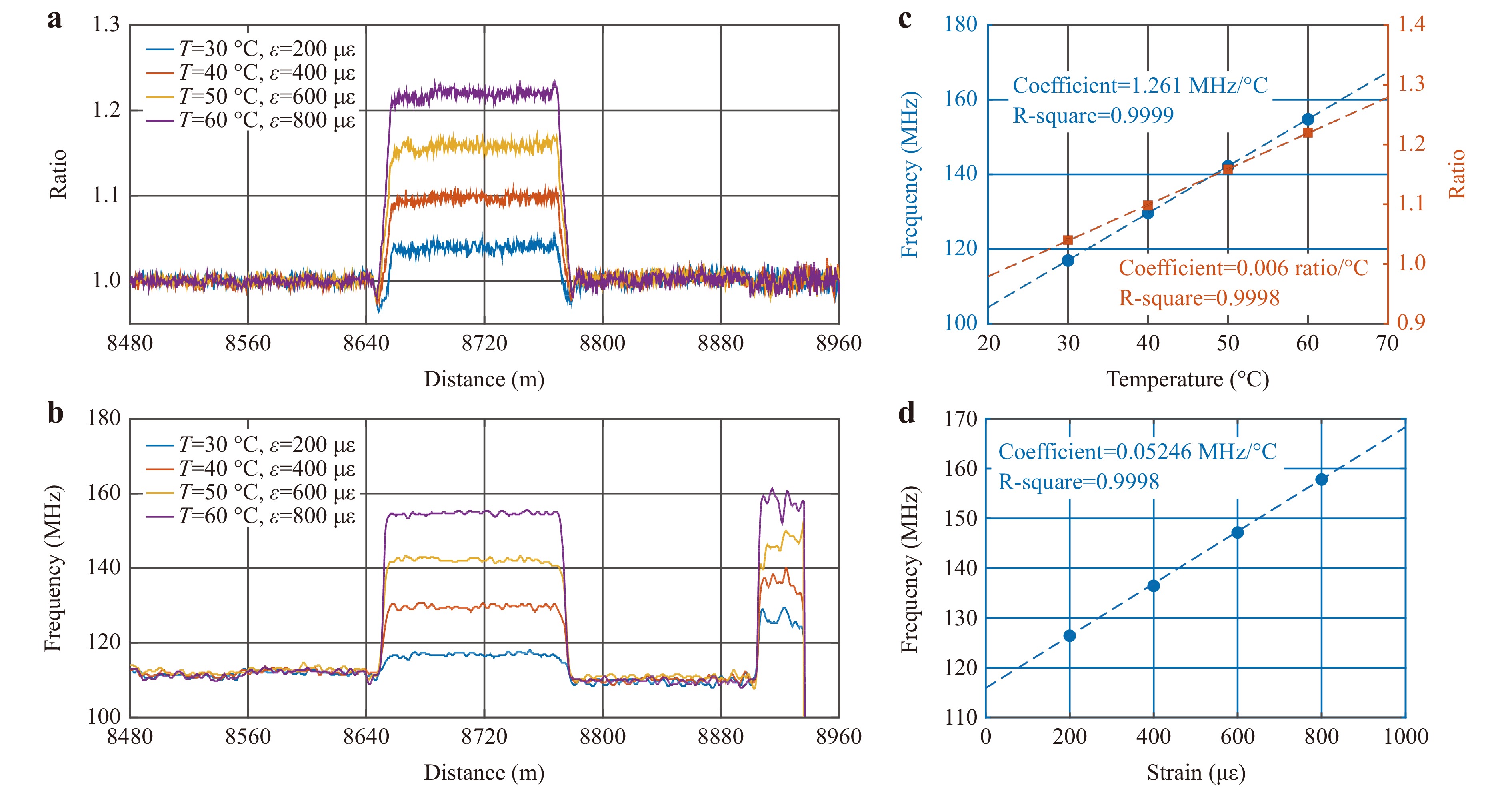
Fig. 3 Experimental results of temperature and strain test sections. a Measured ROTDR results of temperature test section. b Measured BOTDA results of temperature and strain test sections. c Measured temperature coefficients from BOTDA (blue) and ROTDR (orange). d Measured strain coefficient from BOTDA.
The measurement results for the vibrations are shown in Fig. 4. The demodulated differential phase restores the sinusoidal vibration added to the piezo-transducer. The strain spectral density was calculated based on the conversion of the power spectral density. A vibration frequency of 1 kHz was accurately measured, and the noise base reached 10 pε/√Hz at 1 kHz. The noise base was slightly higher than that of the conventional φ-OTDR system, primarily because of the spontaneous Brillouin scattering of the Brillouin pump pulse. Because the optical fibre is placed directly on the experimental bench without isolating temperature and vibration, the noise floor at low frequencies was relatively large, which similarly occurs in the conventional φ-OTDR scheme for the same arrangement28.
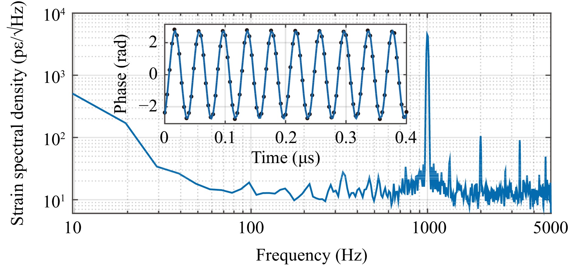
Fig. 4 Measured φ-OTDR results for vibration test section.
The necessity of shifting one bit in the decoding process for BOTDA and ROTDR was indicated in the experimental results. For BOTDA, if the shifting process described in the conceptual design is not applied, then the measured BGS will be deformed near the fibre section where the BFS begins to change. Fig. 5a shows the measured BGS along the fibre section. The blue line in Fig. 5b represents the BGS at 186 m before signal shifting was applied, and a zigzag deformation can be clearly observed. Before shifting, the spatial information of the BOTDA in the amplified RBS lightwave using the code row of [1 0 1] was 10 m (one bit or one spatial resolution) behind the other two rows. In this case, the BGS contained information at different positions. After applying the spatial shift, the BGS at the same position (186 m, indicated by yellow dots) fitted the Lorentzian shape well, thus satisfying the theory. Clearly, the BGS before signal shifting was the result of superpositioning the BGSs at 176 m (indicated by orange dots) and 186 m.
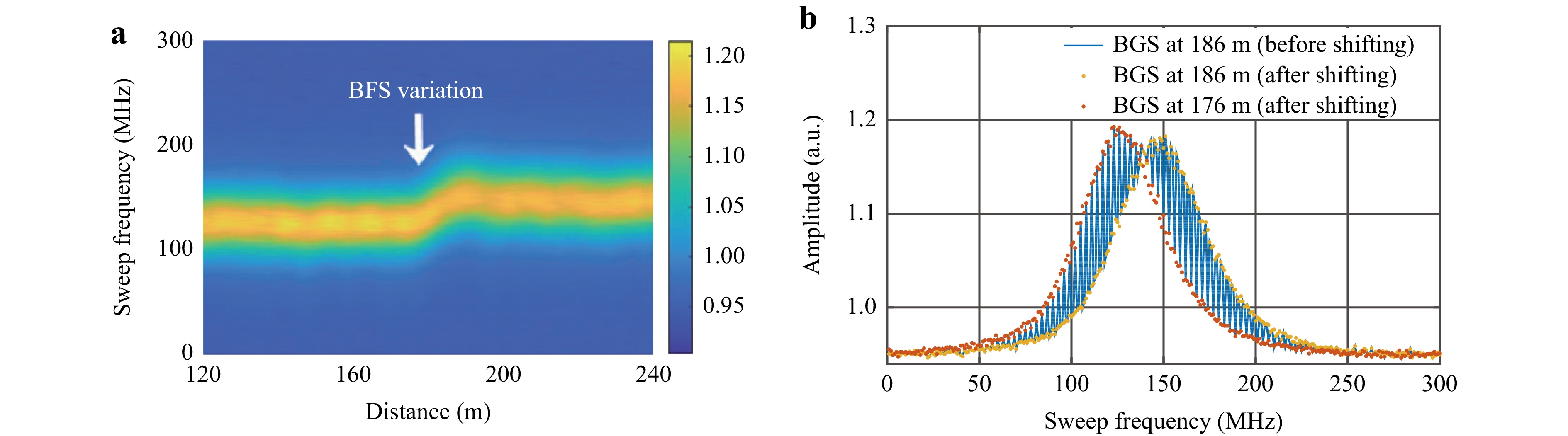
Fig. 5 Effect of pulse coding scheme on BOTDA demodulation result. a Measured BGS along sensing fiber. b Measured BGS at 186 m before shifting [1 0 1] signal one bit ahead, and BGSs at 186 and 176 m after shifting [1 0 1] signal one bit ahead.
For ROTDR, Fig. 6 illustrates the decoding process of the adjusted 3-bit Simplex coding. Here, the Stokes RS lightwave is used as an example, and the anti-Stokes RS lightwave undergoes the same demodulation process. The signal at the fibre entrance is shown for illustration. Fig. 6a shows the Stokes signals of the adjusted coding, where the [0 1 1] and [1 1 0] rows in the adjusted 3-bit Simplex codes are the same. These two sets of signals cannot be used directly in the subsequent decoding process. The results obtained after shifting the signal corresponding to the [0 1 1] row in the time domain are shown in Fig. 6b. These curves are equivalent to those generated using conventional 3-bit Simplex codes. The results of the decoding process are shown in Fig. 6c. RS signals using three different single pulses are obtained, and the only difference was the time delay. Simplex coding can be used for not only demodulating the ROTDR curves in this system, but also for increasing the average number of ROTDR curves under the same measuring time, thereby improving the system signal-to-noise ratio (SNR).
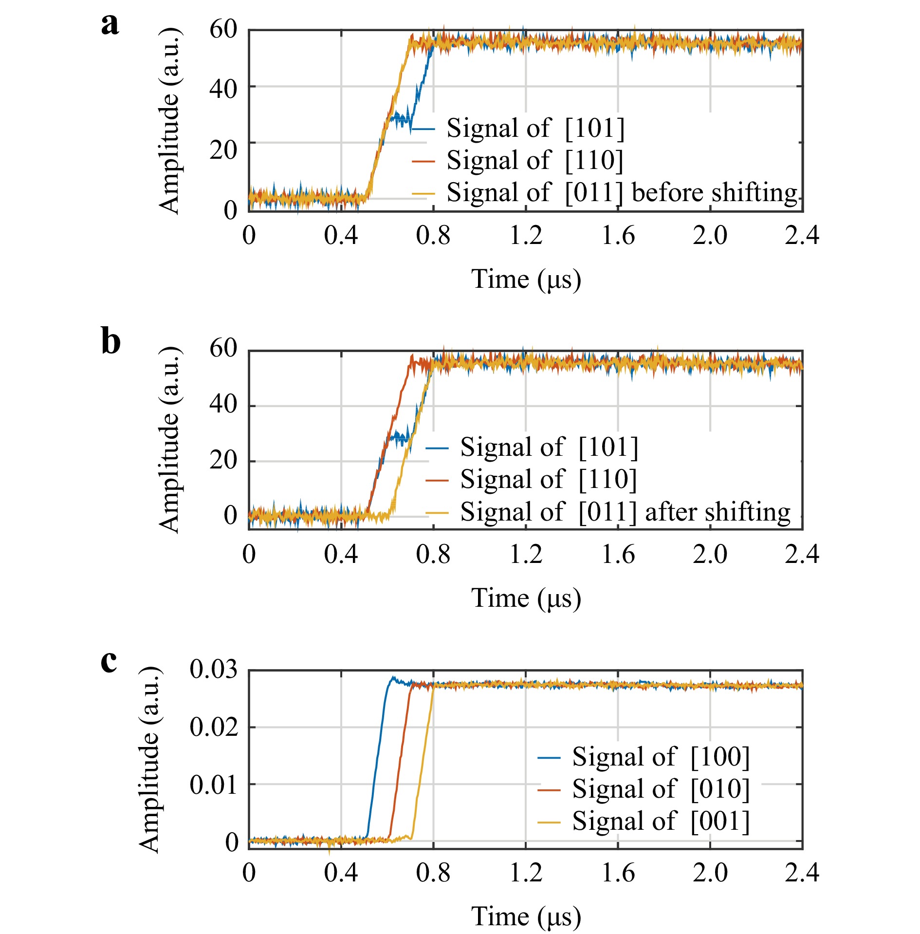
Fig. 6 Demodulated results of intensity of RS Stokes lightwave received in 1450 nm channel. a RS Stokes signal at fiber entrance before [0 1 1] signal was shifted one bit back. b RS Stokes signal at fiber entrance after [0 1 1] signal was shifted one bit back. c Decoded RS Stokes signal with delay of one bit each for illustrative purpose.
-
Table 1 shows a comparison of independent systems with the conventional schemes and the proposed scheme. As shown in this table, the proposed scheme realises simultaneous multiparameter measurements under temperature–strain separation and performs equally well compared with conventional independent systems without additional modulation or devices, albeit with better measurement accuracies. Compared with conventional BOTDA systems, this single-end scheme requires only one fibre end for measurement, which increases its application flexibility. Some independent system schemes achieve advanced performances but require additional schemes or devices, which increases complexity and cost. The proposed system only requires 3-bit simplex coding to separate the Raman scattering of two pulses and can be combined with schemes such as distributed Raman amplification and digital denoising processing to improve the performance using one of the many advanced schemes listed in Table 1.
Scheme Distance Sensitivity or Accuracy Spatial Resolution Additional Schemes
or DevicesParameters/Ability of Temperature–Strain Separation φ-OTDR33-36 12.56 km33 2.45 nε/√Hz 10 m − Vibration/- 1 km34 80 nε/√Hz 2 m 3×3 scheme 10 km35 55 pε/√Hz 6 m PGC scheme 175 km36 12.1 dB (SNR) 25 m Hybrid Raman + Brillouin amplification BOTDA37-41 10 km37 0.23 MHz 2 m − Temperature Strain/No 50 km38 1.8 MHz 2 m Frequency multiplexing 50 m39 0.62 MHz 10 cm Phase-shift-pulse scheme and Walsh code 100 km40 3 MHz 0.5 m DPP scheme and Raman amplification 400 km41 1.25 MHz 2 m Hybrid Raman + EDF amplification
and compensating laserROTDR42-45 4.2 km42 2.95 °C 5 m − Temperature/- 10 km43 1.5 °C − Wavelet transform modulus maxima 26 km44 3 °C 1m Low-repetition-rate cyclic pulse coding 25 km45 4.7 °C 1.13 m Graded-index few-mode fibre The proposed system 9 km 10 pε/√Hz (φ-OTDR)
0.58 MHz (BOTDA)
0.5 °C (ROTDR)10 m 3-bit Simplex coding Vibration Temperature
Static strain/YesTable 1. Performance comparisons of independent systems and the proposed system
The proposed system can significantly reduce the cost and system complexity compared with the three sets of conventional independent systems without using additional schemes or devices. Hence, it is particularly suitable for long-distance distributed sensing applications, such as the real-time and long-term health monitoring of the rail transit system, which requires simultaneous measurements of multiple parameters.
-
Because the limitations of the pulse power for different systems differ, the pulse power design is determined by the strictest limitation. In conventional ROTDR systems, the power of the pulsed light wave should be lower than the power that may induce stimulated Raman scattering (SRS) in the fibre. SRS causes a rapid decay of the probe pulse and adversely affects measurements. However, in conventional BOTDA systems, the pulse power is primarily limited by the modulation instability (MI). Because the MI threshold is much lower than that the SRS threshold46, the pulse power in the abovementioned system should not exceed the MI threshold. Hence, the optical power used for ROTDR in the proposed system is more limited than that in conventional systems; therefore, the average numbers must be improved to guarantee high measurement accuracy. In this experiment, the power of the two pulses was controlled to 176.6 mW to avoid the effects of MI. However, another method can be used to add an independent light source based on this system to realise ROTDR using its RS signal: By setting the wavelength of this independent light source to be significantly different from that of the LO lightwave, the beat signal of its RBS and LO lightwaves will be outside the receiver bandwidth, thus preventing it from affecting the BOTDA and φ-OTDR results. Therefore, although the SNR of the ROTDR is not limited by the MI threshold, the abovementioned scheme increases the system complexity.
-
The demodulation process of the three subsystems comprises the following three steps: 1. The RBS lightwave is directly used for φ-OTDR demodulation after applying a narrow band-pass filter. 2. The amplitude of the RBS lightwave at each position is normalised. To accomplish this, the amplitude of each RBS signal is divided by its amplitude without Brillouin amplification. Subsequently, the BGS at each position is calculated based on the principles introduced in the ‘Conceptual design’ section. 3. A 3-bit decoding method is used to demodulate the Stokes and anti-Stokes RS signals.
Strain and temperature can be separated using the following equation:
$$ \left[ {\begin{array}{*{20}{c}} {\Delta {v_B}} \\ {\Delta R(T)} \end{array}} \right] = \left[ {\begin{array}{*{20}{c}} {{c_{11}}}&{{c_{12}}} \\ 0&{{c_{22}}} \end{array}} \right]\left[ {\begin{array}{*{20}{c}} {\Delta \varepsilon } \\ {\Delta T} \end{array}} \right] $$ (4) The measurement accuracies of the BOTDA and ROTDR were assumed to be ${\delta _\nu }_{_B}$ and ${\delta _{R(T)}}$, respectively. Based on Equation 3, for the proposed system, the measurement accuracies of strain and temperature for the measurement are as follows47:
$$ {\delta _\varepsilon } = \dfrac{{\left| {{c_{12}}} \right|{\delta _{R(T)}} + \left| {{c_{22}}} \right|{\delta _{{\nu _B}}}}}{{\left| {{c_{11}}{c_{22}}} \right|}} $$ (5) $$ {\delta _T} = \dfrac{{{\delta _{R(T)}}}}{{\left| {{c_{22}}} \right|}} $$ (6) -
We acknowledge funding from the National Natural Science Foundation of China (NSFC) under grant numbers 61735015 and 62275151, and the Major Key Project of PCL.
Single-end hybrid Rayleigh Brillouin and Raman distributed fibre-optic sensing system
- Light: Advanced Manufacturing 4, Article number: 16 (2023)
- Received: 27 January 2023
- Revised: 30 May 2023
- Accepted: 31 May 2023 Published online: 13 July 2023
doi: https://doi.org/10.37188/lam.2023.016
Abstract: Backscattered lightwaves from an optical fibre are used to realise distributed fibre optic sensing (DFOS) systems for measuring various parameters. Rayleigh, Brillouin, and Raman backscattering provide different sensitivities to different measurands and have garnered the attention of researchers. A system combining the three principles above can effectively separate the measured strain and temperature completely as well as provide measurements of both dynamic and static parameters. However, the combined system is extremely complicated if the three systems are independent of each other. Hence, we propose a single-end hybrid DFOS system that uses two successive pulses to realise the Brillouin amplification of Rayleigh backscattering lightwaves for combining Rayleigh and Brillouin systems. A 3-bit pulse-coding method is employed to demodulate the Raman scattering of the two pulses to integrate Raman optical time-domain reflectometry into the hybrid system. Using this hybrid scheme, a simultaneous measurement of multiple parameters is realised, and a favourable measurement accuracy is achieved.
Research Summary
Distributed fibre-optic sensing using Rayleigh Brillouin and Raman scattering: Making a fibre provide distributed multi-parameter sensing
Advanced manufacturing is associated closely with precise measurements. As a precise real-time measurement technique, distributed fibre-optic sensing system (DFOS), which requires long-distance simultaneous measurements along a sensing fibre, is in high demand for various industrial applications. Prof. Xinyu Fan and his collaborators, from Shanghai Jiao Tong University, Southwest Jiaotong University, and Peng Cheng Laboratory, proposed a new single-end DFOS to measure multi-parameter along the optical fibre by combining Rayleigh Brillouin and Raman backscattering lightwave with a simple scheme. The team demonstrated the sensing capability of the integrated DFOS that can simultaneously measure static and dynamic parameters of strain and vibration, with a complete separation of strain and temperature. Detailed analyses on the interaction of backscattered lightwave are performed, and a favourable measurement accuracy is achieved.
Rights and permissions
Open Access This article is licensed under a Creative Commons Attribution 4.0 International License, which permits use, sharing, adaptation, distribution and reproduction in any medium or format, as long as you give appropriate credit to the original author(s) and the source, provide a link to the Creative Commons license, and indicate if changes were made. The images or other third party material in this article are included in the article′s Creative Commons license, unless indicated otherwise in a credit line to the material. If material is not included in the article′s Creative Commons license and your intended use is not permitted by statutory regulation or exceeds the permitted use, you will need to obtain permission directly from the copyright holder. To view a copy of this license, visit http://creativecommons.org/licenses/by/4.0/.

 DownLoad: