


HTML
-
Endoscopy is indispensable for optical imaging of tissues located inside the body and, therefore, is of high importance in medical diagnostics and treatment, as well as brain related research1-7. Conventional medical endoscopes are based on the chip-on-tip principle employing a miniaturized camera placed in the probe head or passive imaging elements consisting of a multicore fiber with a small optical imaging system such as a microlens or gradient index lens fixed on the fiber’s end-face. Today, for both of these approaches the probe head dimensions have been reduced to below 1 mm. However, these techniques still suffer from limitations such as a necessity of separate channel for illumination or high image pixelation. In contrast, all-fiber lensless endoscopes enable a significant reduction of the probe size diameter down to a few hundreds of microns, while maintaining the high resolution and reducing the image pixelation8. Therefore, they are promising minimally invasive image guiding mediums to overtake the current state-of-the-art.
Two distinct approaches in lensless endoscopes can be distinguished: multimode fibers (MMFs)3, 9 and multicore fibers (MCFs)10-13, also called coherent fiber bundles. The former offer the highest light collection efficiency and the smallest probe size, because the active area in image guiding is the whole core of the fiber, which can be close to the size of the probe itself 3, 9, 14. However, bending dependent modal crosstalk causes image distortion, which requires complex calibration or decoding, e.g. based on the transmission matrix15. This currently limits the application of MMFs as fast, simple and flexible tools. In contrast, MCFs offer less complex transmission properties. Even though they require thousands of individual cores to maintain high resolution of the image, negligible inter-core crosstalk can be achieved16, 17. In such a case, only the diagonal elements of the transmission matrix must be considered. Inter-core coupling can be sufficiently suppressed by a very high contrast of the refractive index between the cores and the cladding, which corresponds to high numerical aperture (NA). However, to maintain single-mode operation of individual cores with high NA, their diameter must be significantly decreased, which lowers the collection efficiency. Additionally, achieving the NA higher than 0.35 in silica fibers is technologically challenging. Alternatively, inter-core coupling can be avoided by increasing the spacing between the cores. This approach unfortunately reduces spatial resolution and enlarges the fiber’s outer diameter, limiting the applicability of MCF-based endoscopes in domains where miniaturization is crucial, e.g. in the brain surgery. Despite the lower light collection efficiency, the single-mode operation ensuring insensitivity of MCFs to external perturbations makes them a strong competitor to MMFs. Additional advantage of the MCFs is that longitudinal twisting can be applied to obtain not only bending independent image quality, but also image position18, 19.
In MCFs, the periodic core layout based on a hexagonal lattice offers the highest filling factor, i.e., total area of all cores with respect to the area of the whole fiber (close to 0.5 for commercially available imaging fiber bundles, e.g. from Sumita). Thus, for such fibers the smallest probe size is obtained with the highest photon collection efficiency10. However, due to the periodicity of the cores, higher diffraction order images are observed, which can be diminished by further image processing. Alternatively, fibers with randomized core arrangement can be used to eliminate or suppress these artificial images13, 16, 19-21. The technology to create fully aperiodic layout of cores is currently only achievable by preform drilling, which limits the number of cores down to just a few hundreds20. Approaches based on building the fiber preform by disorganized stacking of tailored rods with a single offset core16, 19 or a few cores subgroups21 have been proposed to create quasi-aperiodic layouts. All these approaches result in a very low filling factor (most often below 0.03), and, as a result, they suffer from low collection efficiency. Additionally, both in periodic and aperiodic MCFs the propagation of parasitic bandgap modes in the cladding between the cores is possible. These modes are highly sensitive to external perturbations because they are weakly guided by means of a localization within a quasi-periodic structure22.
Thermal treatment of fibers is often used to tailor their transmission properties. For instance, thermal expansion of cores (TEC)23, 24 is a known technique in low-loss splicing of fibers with different diameters of the cores25. On the contrary, fibers with decreased diameter find applications e.g. in sensing and monitoring of light-matter interactions26, 27. Interestingly, tapering down the MCF is also a way to increase the photon count and contrast28. Such a surprising effect is achieved with two phenomena. First of all, the core diameter is decreased, whereas the mode field diameter remains approximately constant. Thus, the filling factor at the facet of the fiber is effectively increased. Secondly, the cores of the tapered fiber are located closer to each other. Both of these effects result in the reduced intensity of the diffraction orders, and therefore, the signal-to-noise ratio in the image increases.
In this paper, we demonstrate a possibility of increasing the MCF’s active area and, therefore, improving the image quality, by thermal expansion of cores at the distal fiber end-face (i.e., the application side, closer to the specimen) without changing the fiber’s outer diameter, see Fig. 1a. Such a modification, relying on diffusion of core dopants into the cladding region, leads to an increased collection of light by the cores and, additionally, a decreased guidance of bandgap modes in the cladding. In this way we improved the collection efficiency, contrast and signal-to-noise ratio in the image while maintaining the fiber’s insensitivity to external perturbations, such as bending. This is of special importance in biomedical applications and imaging of fluorescence, in which the maximum illumination power is limited by phototoxicity or saturation effects. We present the advantages of the proposed approach in lensless single-shot imaging applications. However, similar improvement can be achieved in this way also in other imaging techniques and systems including confocal imaging and raster scanning method, based on lensless and lensed endoscopes. We will refer to the fiber with thermally expanded cores with a shorthand “TEC fiber”, and as depicted in Fig. 1a, side A refers to the unprocessed end-face of the fiber and side B to the end-face with the expanded cores.
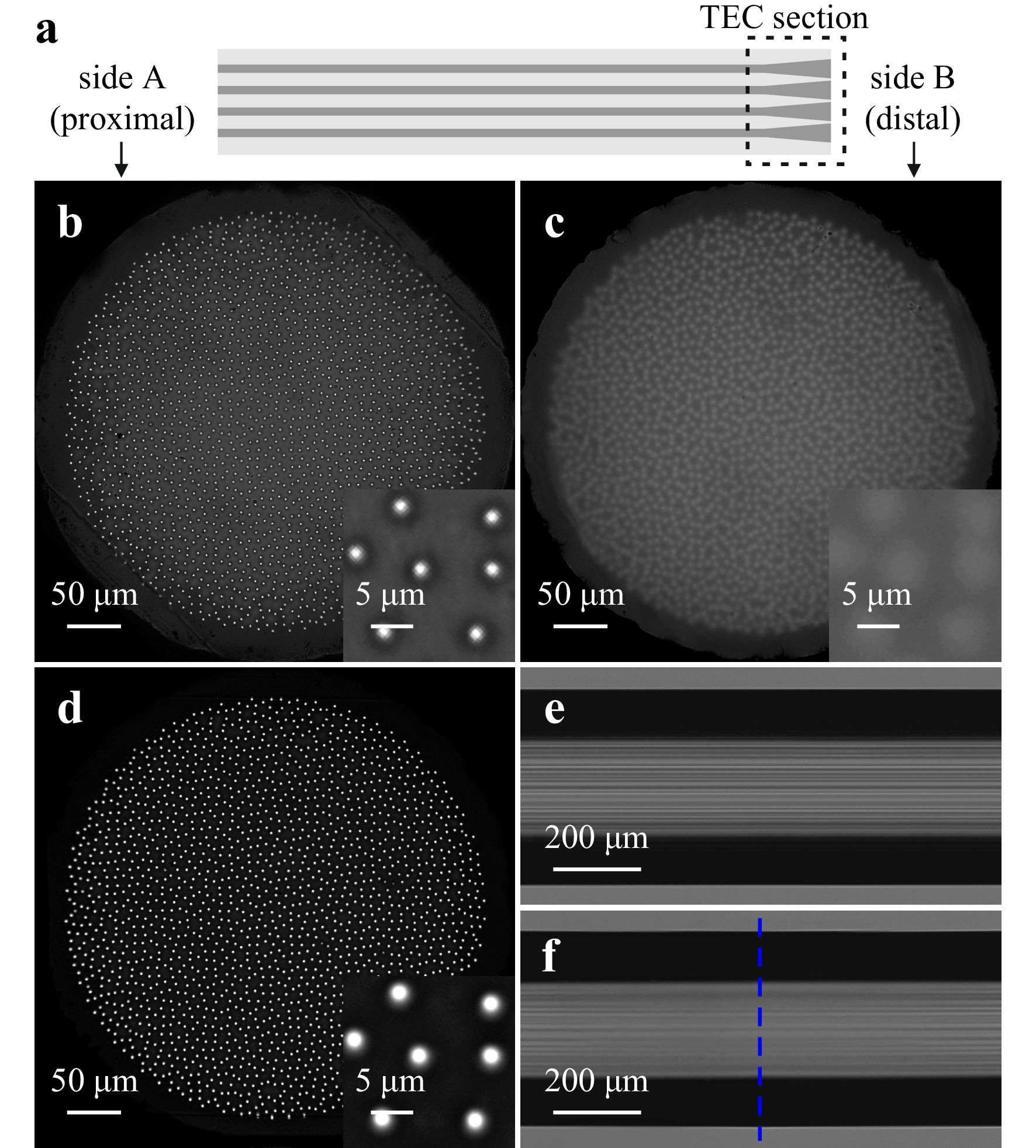
Fig. 1 Scheme of the TEC fiber, where the TEC section is shorter than 1 mm a. Light intensity distribution measured at the output of the unmodified fiber b and the TEC fiber’s facet B c and A d illuminated from the other side with an LED. Increase of the light intensity in the cores and decrease of the light intensity guided in the interspaces between cores in the TEC fiber is clearly visible in the insets to b and d. Side view images of the fiber before e and after f thermal processing. The blue dashed line in image f indicates the cleaving point.
-
All experiments described in this paper were performed at the wavelength of 638 nm, for which the fiber is single-mode, and the inter-core coupling is negligible (below -30 dB). In experiments with coherent illumination we used a 638 nm continuous wave fiber-coupled laser with output power of 26 mW. In experiments with incoherent illumination we used an LED chip with a central wavelength of 628 nm and full width at half maximum (FWHM) of approximately 20 nm, transmitted through an interference bandpass filter with a central wavelength of 638 nm and FWHM of 3 nm. In all experiments comparing the TEC fiber with the unmodified fiber, the illumination and detection conditions were kept constant to ensure reliable comparison of the results.
-
We fabricated a fused silica fiber with 1830 quasi-randomly arranged germanium doped cores. The quasi-aperiodic core layout was realized by iterative stacking of randomly rotated rods with three individual cores19, 21. The light intensity distribution measured at the output of the fiber illuminated with an LED from the other side is shown in Fig. 1b. The outer diameter of the cladding is 448 µm, within which the cores are distributed over a central diameter of 394 µm. The estimated diameter of each individual core is approximately 1.3 µm, resulting in a filling factor of 0.015. Average measured cut-off wavelength of the cores is 520 nm and their measured NA is approximately equal to 0.18.
-
To thermally expand the cores we used a Fujikura LZM-100 fiber processing station. The gradual profile of the dopants diffusion along the fiber was realized by heating the fiber from two orthogonal angles with a CO2 laser beam with gradually increasing power. Both, the final diameter of the thermally expanded core and the longitudinal gradient can be controlled by the time of heating and the maximum applied power23. In this particular experiment, we increased the power of the laser beam from 0 to 20 W linearly over time of 120 s and kept the laser at maximum power for additional 30 s. To avoid curving of the facet, the thermal treatment was applied a short distance away from the fiber’s end-face. During the heating procedure, the fiber was clamped on both sides of the heated section to also avoid longitudinal deformation. As no pulling force was applied during heating, the outer cladding diameter remained constant. After the thermal modification the fiber was cleaved at the central point of the treated section. In this way, we enlarged the active area of the fiber’s facet without changing the size of the probe. Side view images of the fiber before and after the thermal processing are shown in Fig. 1e, f, respectively. In the latter, one can see a gradual blur of the cores along the fiber from the sides of the image toward the center, corresponding to gradual increase of the cores' diameter. The total length of the TEC section after cleaving is below 1 mm. The light intensity distribution at the processed facet B of the TEC fiber is shown in Fig. 1c. Based on images of the facets before and after processing, we estimated that the core diameter increased by a factor of 2.8, which resulted in the increase of the filling factor from 0.015 to 0.12. In Fig. 1d we show also the unprocessed facet A of the TEC fiber illuminated with an LED from side B. Comparing Fig. 1b, d, one can easily notice the increase of light intensity in the cores and significant decrease in the interspaces between the cores of the TEC fiber. Detailed and quantified comparison is presented in the Results and discussion section.
-
Small variations in dopants concentration and diameters between cores of MCFs are unavoidable in the fabrication process. They result in different effective refractive indices in the cores, which create an irregular phase distortion of the beams transmitted in individual cores. In lensless imaging, this phase distortion has to be corrected by applying a phase mask along the path of light propagation, e.g., with use of a digital optical phase conjugation applied on a spatial light modulator (SLM)29, 30 or a 3D printed phase mask, as we have recently shown31. Alternatively, approaches for image retrieval from the speckle patterns without correcting the phase distortion have been reported32-35. In our experiments we used the optical setup shown in Fig. 2. The distal end of the fiber corresponds to the application side, where the specimen is placed (inside of the body). The proximal end is the instrument side, where the detection takes place (outside of the body). Beam splitters BS1 and BS2, mirrors M1 and M2 and the camera CAM1, observing the fiber’s proximal facet, create a reference arm of a Mach-Zehnder interferometer. Using interference between the reference beam and the beam transmitted through the fiber we measure the phase distortion, which is then compensated by an inverse phase mask displayed on the SLM36. After the phase calibration, the reference arm of the interferometer is blocked by a shutter placed after BS1 and the object is placed at the distal end of the fiber. The object plane is imaged on the camera CAM2 by the lens L4. The results shown in Fig. 3 were obtained with use of CAM1, whereas the images shown in Figs. 4−6 were registered with CAM2.
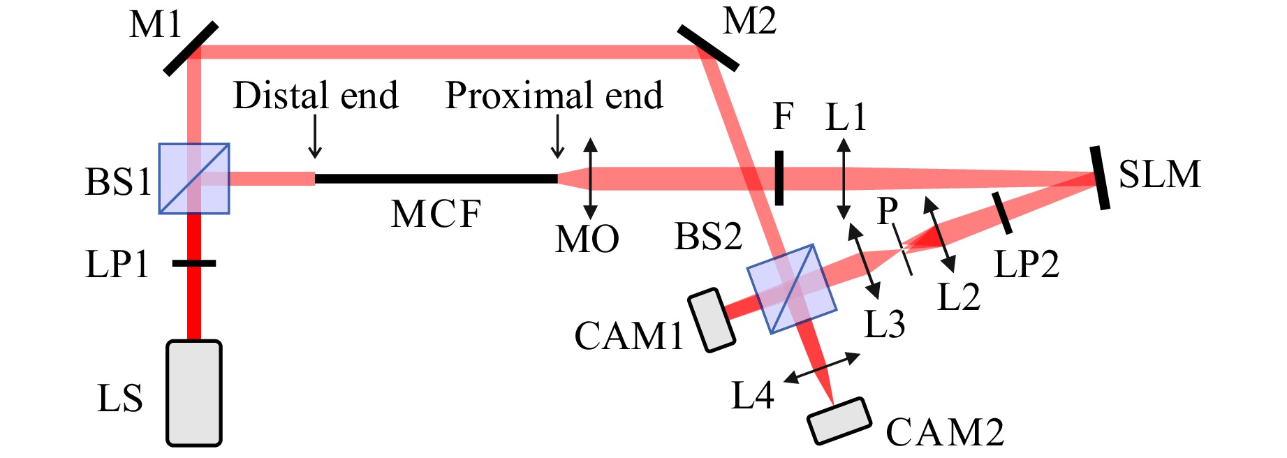
Fig. 2 Optical setup used for phase distortion correction and imaging: LS - light source, LP - linear polarizers, BS - beam splitters, M - mirrors, MCF - multicore fiber, MO - microscope objective, F - bandpass filter, L - lenses, SLM - spatial light modulator, P - pinhole, CAM - cameras. CAM1 is used for phase distortion measurement and CAM2 is used for imaging.
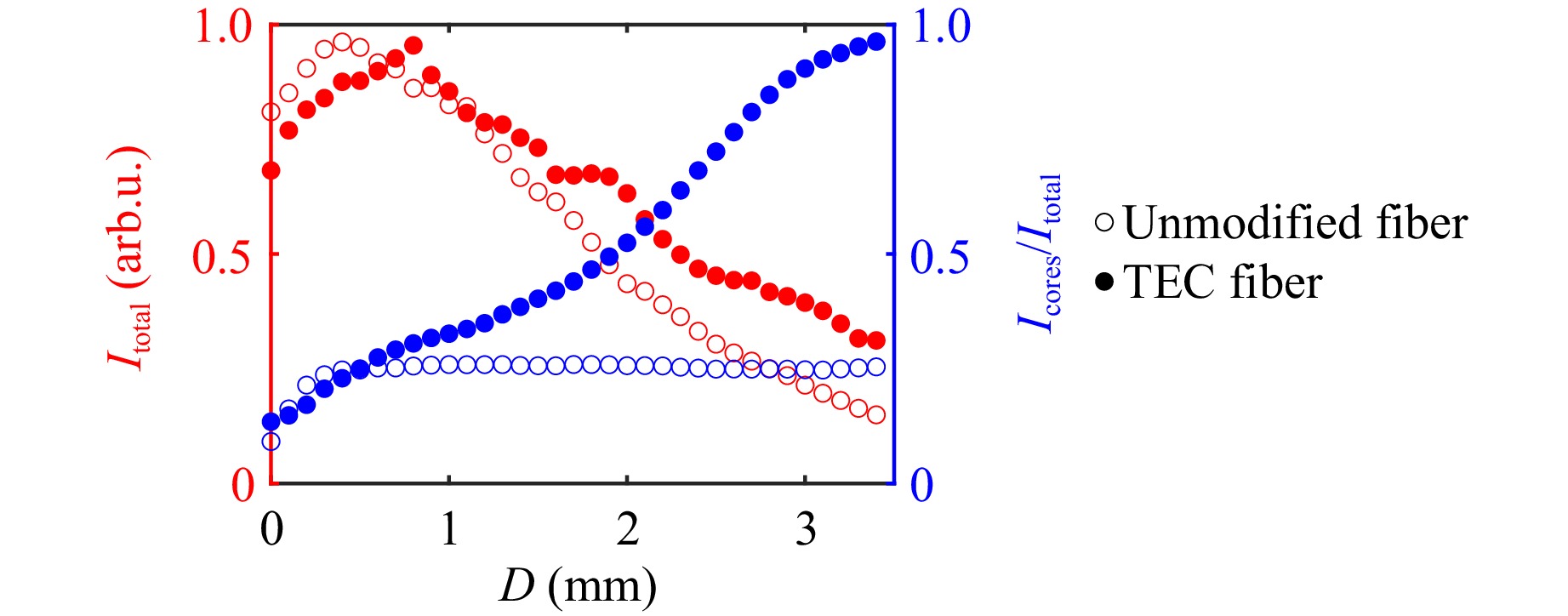
Fig. 3 Measured normalized intensity of light guided in the whole fiber and fraction of intensity guided in the cores as a function of distance of a point source from the fiber’s distal end.
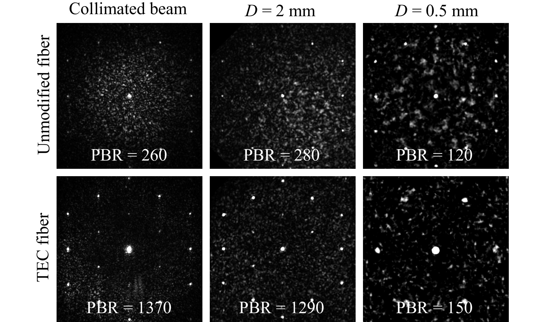
Fig. 4 Camera images of a collimated beam and a point source positioned at different distances from the fiber’s distal facet imaged through the unmodified and the TEC fiber. The corresponding PBR values given in each image provide a quantified comparison of the results.
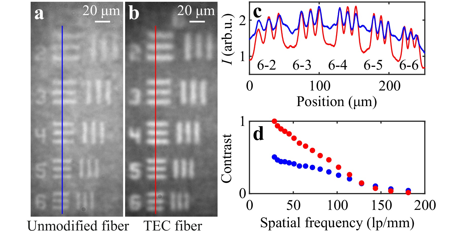
Fig. 5 Elements 2–6 from group 6 of the 1951 USAF test chart imaged through the unmodified a and the TEC b fiber. Intensity across the lines marked in these images c and contrast as a function of spatial frequency of the pairs of lines in the test chart d for the unmodified (blue) and the TEC (red) fiber.
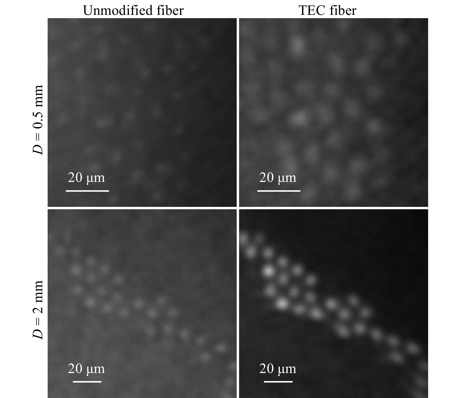
Fig. 6 Light reflected from microbeads imaged through the unmodified and the TEC fiber when the sample was placed at the distance of 0.5 and 2 mm from the fibers' distal end.
-
For experiments described in this paper we used fibers with length of 10 cm. However, our major findings are independent of the fiber’s length, as the collection efficiency is only defined by the incoupling at the fiber’s facet. Additionally, no noticeable transmission losses between the modified and unmodified section of the TEC fiber were detected. The propagation of light in the interspaces between cores is dependent on the fiber’s length and bending. However, we confirmed experimentally that even for a few meters long pieces of fiber wound on the spool with a radius of 10 cm the bandgap cladding modes are still present. They can be significantly suppressed by sharp bending. We observed experimentally that the bending radius must be smaller than 2 cm to reduce the intensity of light in the cladding by approximately 90%. For imaging fiber bundles with diameters of a few hundreds of micrometers such a small bending radius might cause breaking of the fiber. During the imaging experiments presented in this paper, the fibers were approximately straight. Therefore, the contrast gain demonstrated here might be higher than it would be in longer and bent fibers. Nonetheless, with this paper we aimed to demonstrate that the TEC method is valuable not only to increase the collection of light by the cores, but also to suppress the background light collected by the cladding.
As the diffusion process does not alter the cut-off wavelength significantly, the gradual change in the refractive index profile over a length of around 1 mm ensures lossless conversion of the fundamental mode in the TEC section24. As a result, no higher-order modes were observed at the outputs of the TEC fiber regardless of the direction of light propagation. As a trade-off for increasing the mode field diameter and lowering the maximum dopant concentration of an individual core by thermally induced diffusion, the NA in the TEC fiber decreases. We measured a change from 0.18 in the unmodified fiber to 0.13 in the TEC fiber. For this reason, the positive features of the TEC fiber are especially evident for specimens placed at a larger distance from the fiber’s distal facet. To demonstrate the range of improvement in the TEC fiber, we illuminated both the unmodified and the TEC fiber from side B with a point source, i.e., a laser beam focused by a microscope objective (100x, NA = 0.8), at different distances from the fiber and recorded the intensity distribution at the facet A with a camera. In these images, we measured the total intensity of light guided in the whole fiber, and by applying a core layout mask, also the intensity of light transmitted in the cores, shown in Fig. 3. Results for both fibers were normalized with the same factor, ensuring comparability. The decrease of total light for both fibers at larger distances is due to high NA of the objective used for illumination. Above the distance of approximately 0.5 mm, the incident beam has a larger diameter than the fiber. For the point source placed at the distances smaller than 0.5 mm, the unmodified fiber guides slightly more light thanks to its higher NA, however, both fibers guide the same fraction of light in the cores. Above that distance, the larger mode field resulting in the higher filling factor gives the TEC fiber a significant advantage, as it not only collects a higher total intensity than the unmodified fiber, but also guides a larger fraction of it in the cores. At the working distance above 3 mm, the performance of the TEC fiber is exceptionally better, as it guides 2.3 times more total intensity and nearly all of it is confined in the cores, instead of interspaces between them, thanks to the higher filling factor.
The final diameter of the expanded core depends on the applied power of the CO2 laser and the time of heating. The length of the modification can be additionally controlled by longitudinal translation of the fiber while heating or by defocus of the heating beam. The initial distance between the cores, the core enlargement factor, the refractive index contrast between the core and the cladding, as well as its change along the modified section affect the inter-core coupling17. Therefore, the length of the modification and enlargement factor must be optimized individually for each MCF design and the application. In our experiments, during the heating process the fiber was static to obtain the shortest optical path over which the cores were expanded. In this way, the lowest inter-core coupling and independence of the transmission properties upon bending of the fiber were ensured.
Inter-core coupling before and after thermal processing was measured by selective illumination of one core and comparison of the power in the excited core and neighboring cores at the output of the fiber. The statistics based on 50 randomly selected cores revealed that average inter-core coupling before processing was below −30 dB, whereas after processing it increased to −16 dB. This drastic change is caused by the significant increase of the overlap of the adjacent cores induced by the diffusion. It is worth noting that we confirmed experimentally that bending the TEC fiber does not affect its output field distribution. This is because the coupling occurs only in the TEC section, which is shorter than 1 mm, and therefore, similar insensitivity to bending is ensured in imaging applications as for the unmodified fiber.
Light propagating within the cores forms the image, whereas light propagating within the cladding causes the increase of the background intensity and noise. To compare the quality of the images guided through both fibers, we imaged a point source positioned at different distances from the fibers’ distal facets, see Fig. 4. For each image we calculated a peak-to-background ratio (PBR) as a ratio of a maximum intensity of the central spot over a mean value of the intensity of the background. Because the fiber is only quasi-aperiodic, the higher-order diffraction maxima are still visible in the image, however, their intensity is suppressed by 15 dB with respect to the intensity of the central spot16. Clearly visible higher brightness of the diffraction maxima for the TEC fiber is caused by an increase of the power propagated in its cores. Their relative intensity with respect to the central spot remains the same as for the unmodified fiber. In every case for the unmodified fiber the PBR was below 300 because of the large fraction of light propagating in the cladding. This result is well below the theoretical value, which for this fiber should be approximately equal to37:
$$ PBR = \frac{\pi}{4}(N-1) \approx{1430} $$ (1) where N is the number of illuminated cores (here N = 1830). For the TEC fiber the PBR was approximately the same at the distance of 0.5 mm, but at larger distances it increased to approximately 1300, i.e., close to the theoretical value. These numbers correspond well to the proportion of light guided in the cores and cladding presented in Fig. 3. For instance, at the working distance of 2 mm, the TEC fiber guides approximately 3.5 times more light in the cores and 1.1 times less light in the cladding than the unmodified fiber, which yields an improvement factor of 3.9, similar to the improvement of the PBR, which is 4.6. When the point source was positioned at the distance of 0.5 mm from the fiber’s facet only a few hundreds of central cores were effectively collecting the light because of their NA. Therefore, the PBRs for both fibers at this distance are significantly smaller than at larger distances.
Larger mode field and lower NA in lensless imaging result in smaller field of view and reduced spatial resolution. Spatial resolution and PBR impact the contrast of the image. To demonstrate this change, we imaged a negative 1951 USAF test target positioned approximately 1 mm from the fiber’s distal facet and illuminated by an LED. In Fig. 5a, b, we show exemplary images of elements 2–6 from group 6 for the unmodified and the TEC fiber, respectively. For a better comparison of modulation depth, in Fig. 5c we also show intensity across the lines drawn in Fig. 5a, b. Additionally, we recorded images of consecutive elements in groups 4–7 placed at the center of the fiber’s field of view and calculated the contrast for each element, see Fig. 5d. Because the spatial resolution of the TEC fiber is lower, the slope of the contrast function is higher and for higher spatial frequencies the contrast for the TEC fiber becomes smaller than for the unmodified fiber. Both fibers reach the same contrast for a spatial frequency of approximately 130 lp/mm, which corresponds to the width of a single line in the test chart equal to 3.9 µm. Therefore, for objects smaller than 3.9 µm the unmodified fiber is expected to have a better performance.
Finally, we imaged spherical microbeads with an average diameter of 10 µm illuminated by an LED. To bypass the problem of back-reflection of light from the fiber’s proximal facet, we applied external side illumination at the distal side of the system instead of through the fiber. In Fig. 6, we show images recorded when the sample was at the distance of 0.5 and 2 mm from the fibers' distal end. In both cases, for the TEC fiber a larger fraction of light was guided in the cores contributing to formation of an image instead of background. On the contrary, lower filling factor of the unmodified fiber allowed for propagation of higher intensity in the cladding. This increased the background intensity of the images recorded for the unmodified fiber making the microbeads nearly invisible. The contrast of the images is approximately the same for both fibers when the sample is placed at the distance of 0.5 mm. However, at the larger distance it increases by a factor of 2.6 in the TEC fiber. These values again correspond well to the results shown in Fig. 3.
In Table 1 we present the comparison of all the key parameters measured experimentally for the unmodified and the TEC fiber. In the last column we also include the improvement factor obtained by the expansion of the cores. For the results which were measured for different working distances, we give the highest achieved improvement factor.
unmodified fiber TEC fiber IF d 1.3 μm 3.6 μm 2.8 FF 0.015 0.12 7.85 NA 0.18 0.13 − D 0.5 mm 2 mm 0.5 mm 2 mm − Icores 95% 43% 91% 65% up to 2.3 PBR 120 280 150 1290 up to 5.2 C 0.12 0.10 0.15 0.26 up to 2.6 Table 1. Comparison of the measured parameters for the unmodified and the TEC fiber: d - core diameter, FF - filling factor, D - distance of the imaged object from the fiber’s distal facet, Icores - normalized intensity of light guided in the cores (see Fig. 3), C - contrast, IF - improvement factor.
-
Increasing photon collection efficiency of MCFs is a challenge that has to be overcome to open the gate for lensless MCF endoscopes to biomedical applications, such as e.g. imaging of tissue fluorescence used for cancer diagnostics. In this paper, we have presented a novel MCF with cores expanded thermally at the distal end-face. Our key result is that by expanding the diameter of the cores by a factor of 2.8 in a quasi-aperiodic fiber, we were able to increase the total light collection by a factor of up to 2.3, the PBR by a factor of up to 5.2 and the contrast of the image by a factor of up to 2.6. The proposed modification causes the increase of the filling factor without altering the fiber’s outer diameter and, thus, the probe size remains unchanged. The TEC method is especially beneficial for MCFs with initially low filling factor, but it can be obviously applied to fibers with any core size and layout, including periodic hexagonal lattice. Additionally, the same approach can be applied to twisted fibers, ensuring not only the lack of image degradation during bending, but also bending independent position of the image18. As a trade-off of the cores expansion, the crosstalk between the cores increases. However, as the increase only occurs in the TEC section, which is shorter than 1 mm, it is independent of fiber bending, ensuring flexibility desired in imaging of hard-to-reach structures. As the expansion of the cores is a result of the diffusion of the doping of core material into the surrounding cladding, the process is accompanied by a reduction of the NA, which may limit the TEC fiber’s utility in some applications. Nonetheless, the proposed modification is a simple to implement and valuable tool in solving the power delivery issue in MCF endoscopes and combines benefits offered by both MCFs (insensitivity to external perturbations) and MMFs (higher photon collection efficiency). We have shown the feasibility of the TEC fiber in lensless single-shot imaging, and we expect that similar gain can be achieved in other techniques, such as confocal imaging and raster scanning performed with lensed and lensless endoscopes. Moreover, additional thermal treatment of the TEC fiber may bring even more advantages. In this paper, we considered modification of the distal side aiming for higher light collection, which is especially important when the maximum applicable illumination power is limited for example by phototoxicity. In applications requiring specimen illumination through the fiber one can increase the amount of light delivered to the sample by expanding the cores on the proximal side. Furthermore, here we increased the active area of the fiber’s facet without changing the probe size. However, additionally tapering the TEC fiber could bring even further improvement in photon count28 while maintaining the original fiber’s spatial resolution and at the same time offering flexibility and miniaturization, required in a broad range of endoscopic applications.
-
Funded by Deutsche Forschungsgemeinschaft (Grant No. DFG Cz 55/47-1), European Regional Development Fund (100689045), Arbeitsgemeinschaft industrielle Gemeinschaftsforschung (Grant No. 21802), and Saxonian Government.

 DownLoad: