


-
The history of glass making dates back over 5,000 years1–3 and glass optics have been used in scientific instruments for well over 300 years4. As one of the most important materials in human history, glasses left unparallel impacts on our lives from construction to consumer products to scientific endeavors. However, our understanding of glass materials has been largely based on empirical studies in the past, partially due to the fact that glasses are non-crystalline materials and do not have regular lattice structures seen in crystalline materials. As a result, glass melts do not follow the same paths under different rates of cooling. Research has demonstrated and will be thoroughly discussed in this review that this cooling rate dependence during molding is highly repeatable therefore forms the foundation for thermal forming precision optics5. Chalcogenide glasses undergo similar changes and are believed to experience similar property changes during forming6 albeit chalcogenide glasses are in general not as stable as silicate glasses7. Due to limited research, knowledge of chalcogenide glass molding is lacking in comparison but this is being addressed as chalcogenide glasses have seen increasing applications, especially in high volume products such as Lidar8, night vision systems9 and other devices that require high optical performance in infrared band.
To better structure this review, we organize the content as follows: Section 1 provides historical background on glass and highlights the rationale for glass-based aspherical optics. Sections 1.1 to 1.4 further elaborate on the optical system design considerations, benefits of glass over polymers, key challenges in glass lens fabrication, and the scope and assumptions of this review. We focus primarily on single-element glass molding processes for imaging lenses but also emphasize broader applicability in non-imaging systems. Specifically, Sections 2 through 7 cover key aspects including the evolution of molding equipment, mold material selection and fabrication, optical glass properties, modeling of heat and stress during molding, and emerging techniques such as wafer-level glass molding (WLG) and rapid heating strategies.
In addition to camera optics and traditional imaging modules, precision glass molding has been increasingly implemented in advanced applications such as infrared optics for LiDAR and night vision, MEMS packaging, biomedical microoptics, and photonic sensor arrays. For example, wafer-level glass molding has enabled scalable fabrication of infrared microlens arrays10, while integrated molded glass elements are now used in MEMS actuators and sensor packaging11. Recent developments also include glass-based microfluidic sensors12 and bio-inspired curved optics for wearable devices13. Furthermore, the synergy between additive manufacturing and molded optics has opened new opportunities for hybrid glass-fabrication workflows, as detailed in “Additive manufacturing of glass: from science to applications”14.
By integrating historical evolution, process physics, mold fabrication technologies, and application-oriented developments, this review aims to serve as a comprehensive reference for both researchers and engineers working at the interface of optical design and precision manufacturing.
-
Typical optical elements include lenses, mirrors, apertures, and barrels15. Precision lenses have been in high demand for many industrial and consumer products in recent decades as consumer products such as cell phones, onboard cameras for self-driving cars and surveillance cameras became ubiquitous. After continuous research and development, polymeric lenses may have reached the performance limits16 and room for improvement in manufacturing processes is significantly reduced. In addition, polymeric lenses inherently suffer from low thermal stability, difficult in index match for color correction due to the fact that there are only a few polymeric materials to choose from and none has high Abbe number that many glasses have. For example, a plastic material often used in cellphone camera modules for color correction, OKP4 has an Abbe number of only 2717. Traditional diffractive lens designs can be an efficient approach for chromatic aberration correction but cannot be easily used in high aperture applications. Most issues plastic materials encountered can be ameliorated by switching to glass lenses if manufacturing difficulty can be managed. These are exactly the problems glass molding were designed to address. We do believe however that hybrid optical systems, i.e., systems of both plastic and glass lenses will appear first then ultimately all glass lens system may become possible or necessary18.
It is intuitive that compression molding is inherently a freeform replication process. Freeform optics are unique elements without a clear axis of symmetry, however applications using freeform optics today are still limited to niche places such as head up display, compact camera systems and some scientific instrument19,20. The majority of molded glass optics today are aspherical lenses21. These products are manufactured in billions each year for consumer devices, i.e., cell phone cameras and on-board camera modules in automobile and surveillance cameras. We believe that the main roadblock to full implementation of molded glass aspherical lenses is manufacturing cost. It is accepted without clear justification in industry that cost of glass lens manufacturing needs to be compatible with injection molding (of plastic lenses) even though performance of glass lenses in many areas are superior to that of plastic, e.g., ability to reduce dispersion and withstand temperature changes during use, just to name a few. Fig. 1 illustrates the overall process and some existing and possible industrial and scientific applications of this technology.
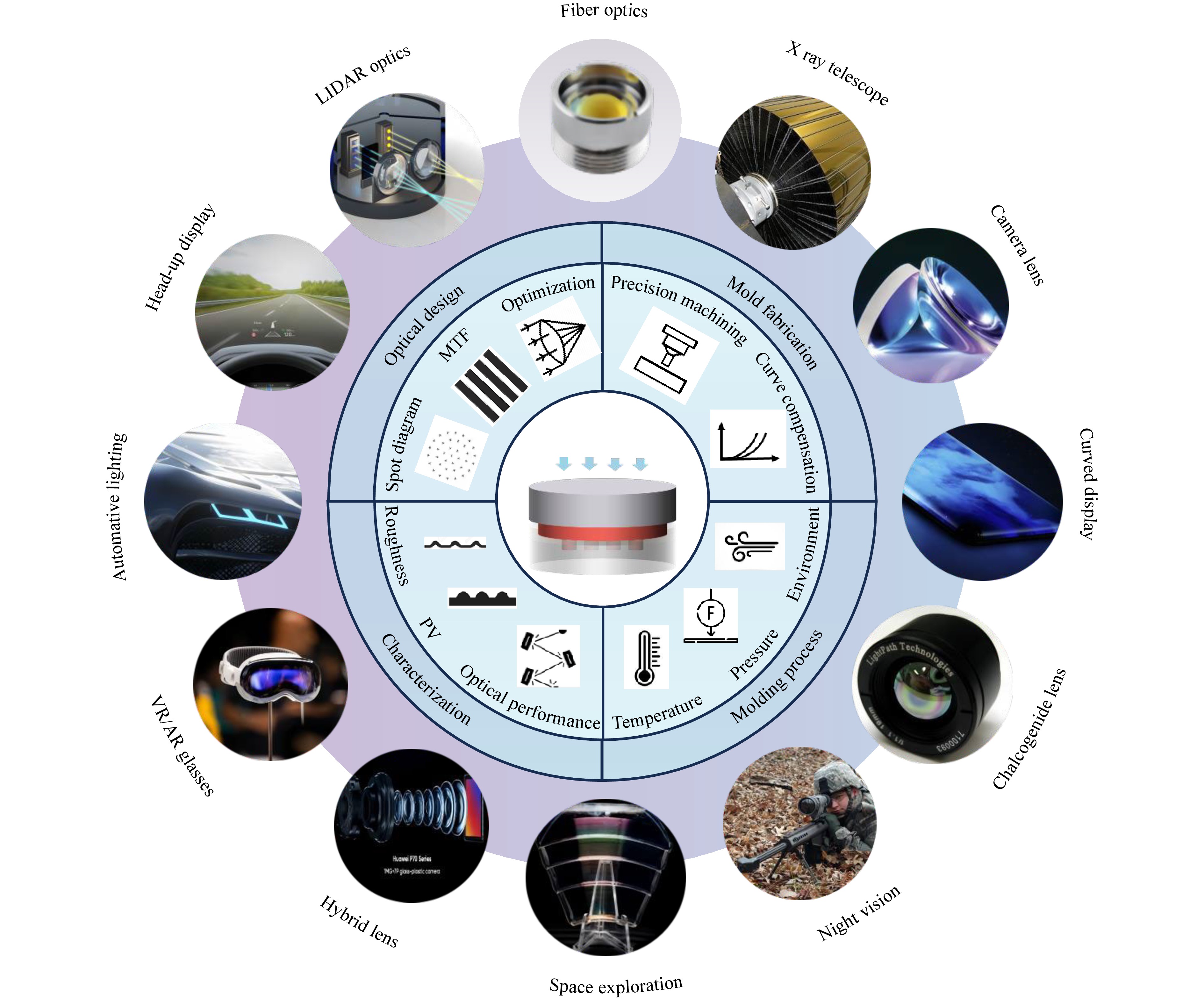
Fig. 1 Schematic of commercial and scientific applications of molded glass lenses, including categories of optical design, mold fabrication, molding process, and characterization. The central image illustrates applications, including aspherical lenses for fiber communication, x ray telescope mirrors for space exploration that were thermally slumped, a commercially available molded aspherical lens from Edmund Optics, a curved glass display, a commercial molded infrared/chalcogenide glass lens in a housing, a thermal weapon sight, a molded MODE lens ring segment for space-based telescope design. Examples also include glass-polymer hybrid lens, and molded glass lenses for AR/VR applications, automobile lighting assemblies, automobile head-up display. All figures are reproduced from website page under CC BY 4.0.
In this review, we attempt to achieve several goals. First of all, we will chronically describe the history of compression molding technology with brief mentioning of early design of glass molding press and molding results. Secondly, we summarize molding process using scientific approaches based on fundamental physics, both experiments and numerical modeling. Thirdly, we will carefully review methodologies used in compression molding of glass lenses and demonstrate the molded lens performance using different experiments. This review is not intended as an abbreviated textbook, instead, we explore the history and highlight key elements of this technology. The overall organization of this review is as follows: Section 1 is background and history. Section 2 goes back to optical design for high volume production. Section 3 focuses on mold fabrication. Section 4 discusses optical glass material and explains the fundamentals in compression molding. Section 5 summarizes current rapid heating methods in compression molding. Section 6 offers an overall view of wafer level molding and Section 7 is dedicated to glass molding improvement and optimization before closeout with the summary.
-
For an imaging optical system, spherical aberration is one of the primary sources of errors22 (others include chromatic aberrations and coma). To mitigate this problem, different aspherical lenses are essential23. Optical systems such as camera modules for consumer applications are typically high-volume products, requiring an extremely large number of high precision aspherical lenses (~billions) are needed. As of today, aspherical lenses are primarily made using injection molding of a few polymeric materials such as polycarbonate (PC), polymethylmethacrylate (PMMA), polystyrene (PS) and polyester (OKP4)24. The advantages of plastic lenses are many, often including low fabrication temperature and relatively easy mold fabrication where diamond turning of nickel plating can satisfy most mold fabrication needs. However, from a material standpoint, glass is a much better optical material: better high temperature performance, low birefringence, low dispersion, high scratch resistance and wide selection of different chemical compositions25. Consequently, system designers face a classic trade-off between the optical performance of glass and the manufacturing latitude and cost advantages of polymers. Reflecting this, based on achievable tolerances26, Table 1 also discusses relative cost impact and pros/cons associated with tightening each specification, clarifying how improved image quality and assembly stability typically come at the expense of narrower process windows, longer cycles, and greater yield sensitivity.
Manufacturing tolerance Feature Standard quality Precision quality Relative cost impact Pros and cons Center thickness ±0.025 mm ±0.012 mm ++ Better assembly stability; needs longer soak/slow cool, yield more sensitive Diameter ±0.030 mm ±0.010 mm + Tighter fit and alignment; more edge rework and tool iterations Surface deviation - Irregularity (fringes) 5-2 3-1/2 +++ Higher accuracy; narrower window, hard to characterize Wedge 0.05 mm 0.01 mm ++ Less astigmatism/ghosting; higher fixturing and centering accuracy needed Axis alignment 5′ 2.5′ ++ Lower system bias; more mold pairing and setup time Scratch-dig 60-40 20-10 ++ Lower scatter/stray light; stricter cleaning/coating, increasing scrap risk Antireflection coating Single layer R < 1.5% per side Multilayer R < 0.5% per side ++ Higher transmission, less glare; longer chamber time, more steps Index of refraction ±0.001 ±0.0003 +++ Better athermal/color control; tighter batch control/screening Abbe number ±0.8% ±0.5 ++ More stable chromatic correction; higher material screening cost Sag ±0.015 mm ±0.010 mm ++ Lower profile error; more mold iterations, slower cooling Table 1. Manufacturing tolerances for molded glass aspherical lenses, reproduced from26
Traditional high volume manufacturing processes for glass lenses are predominantly designed for spherical lenses: Preforms/blanks are ground into basic lens shapes, then fine-ground or lapped to remove the bulk of surface and subsurface damage. Polishing is performed using compounds such as cerium oxide or aluminum oxide to achieve an optical finish in the nanometer range27. Grinding and lapping are considered deterministic but polishing of an optical surface with full aperture tool is however a divergent process that often results in deterioration of the surface figure. It has been demonstrated in practice that using traditional grinding/lapping/polishing is not the answer to manufacturing of high volume aspherical glass lenses, an alternative that has been the focus of intense research and development in the last decades is compression molding of glass aspherical lenses. Although glass molding process is freeform in nature, its most important application however has been the aspherical lenses, precisely for reasons outlined next.
-
For a typical camera lens module on the market today, almost every lens element is aspherical (some lens geometries can be dramatic, i.e., drastically deviating from spherical surfaces, e.g., surface 12 of lens 6 in Fig. 2). For example, in a patented cell phone lens design, all six plastic lenses were aspherical for optimal performance28. Fig. 2 shows a generic plastic lens camera module with six aspherical lenses. Technically, aspherical lenses are best used to compensate for spherical aberration, and some chromatic aberration and coma29. As shown in Ref. 22 (page 107) spherical aberration is part of the Seidel aberrations, it just happens that spherical lenses naturally have a high degree of spherical aberration and the fact that spherical lenses are also responsible for spherical aberration in an optical system with glass lenses is largely a coincidence. Further discussions on optical aberrations can be found in many publications and references therein30,31.
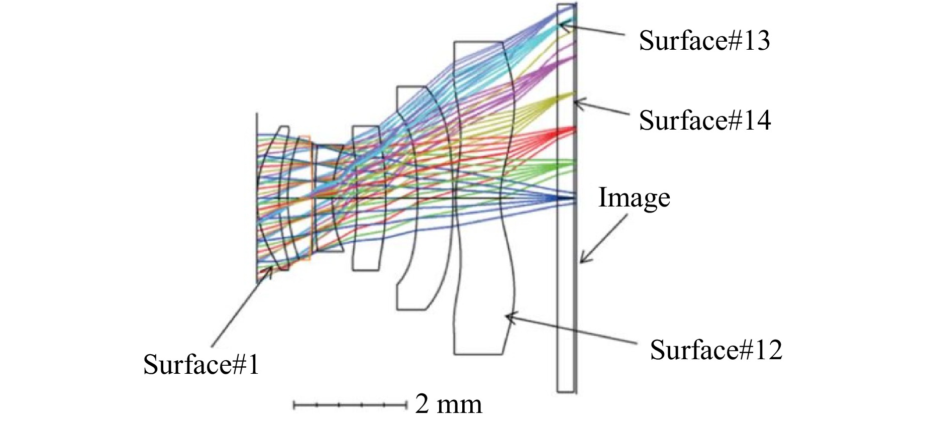
Fig. 2 A six lens camera module with 6 aspherical plastic lenses32.
Due to dispersion of optical materials, chromatic aberrations are common in all broadband imaging systems. Aspherical lenses are not naturally designed for reducing color aberration, but many glass materials have lower dispersion and higher Abbe numbers33 and can be more effective than plastic lenses in color correction. Although diffractive and meta surface structures are known for providing strong color correction, these optical elements have a drawback—efficiency drops quickly as incident angles increases therefore are often limited to zoom lenses where field of view (FOV) is small34,35. Manufacturing of diffractive and meta surfaces can also run into production issues36,37. Limited production of diffractive lenses in consumer optics have been reported but details of optical design including lens materials used in these diffractive lenses were not clearly specified38. Some lens design details and diffractive efficiency of a commercial camera utilizing a diffractive optical lens are shown in Fig. 339. In addition to color correction, diffractive lenses are also used to reduce weight (historically this traces back to the original Fresnel design to reduce glass lens volume in the light house40), this is exemplified not only in consumer products41 but also in the recent scientific work in MODE lenses as the space-based telescope primary lens34. In this design, FOV is also very typical for an astronomical telescope as such the energy scattered by the transition zones does not get focused back on imaging plane, i.e., the transition rings slightly lower contrast are not quite visible on the imaging plane. Other applications of thin and large molded glass lens may be seen in wafer level glass molding (WLG) where high aspect ratio is a byproduct of the effort of going for high production rate, similar to impact of wafer size to semiconductor industry. More on WLG will be described in section 6. Diffractive and wafer level molding are two promising diversion of glass molding technology and are expected to see more applications in the future42,43.
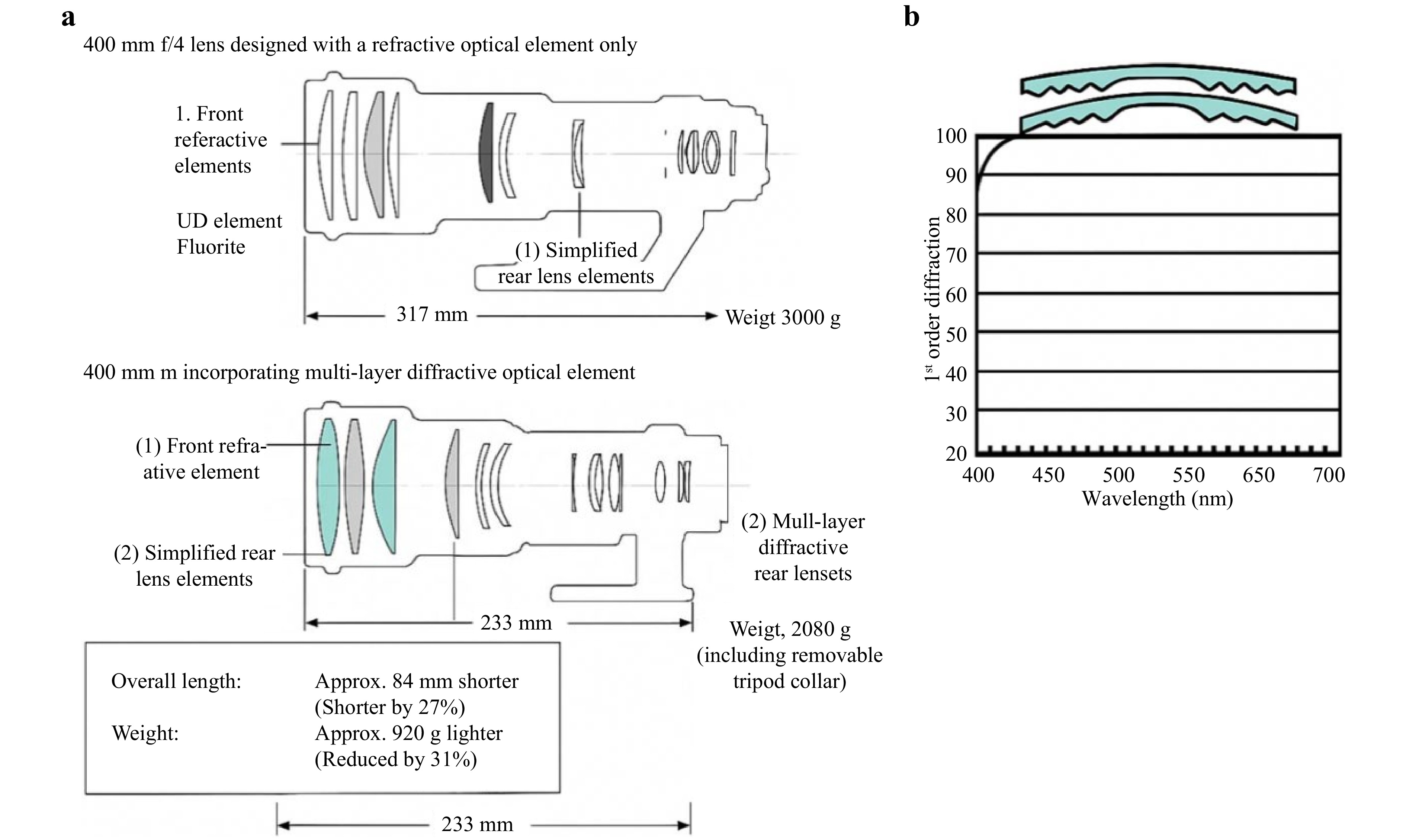
Fig. 3 a laminated diffractive lens combine used in telescope zoom lens which shows the comparison of a 400 mm f/4 lens using (top) conventional refractive optics and (bottom) a design incorporating multi-layer diffractive optical elements (DOEs). Each layout includes specialized elements such as UD glass, fluorite, and a DOE. The DOE enables significant size (−27%) and weight (−31%) reductions by combining dispersion control and aberration correction into a single element. b 1st order efficiency across the visible waveband39. Notice the efficiency reaches almost 100% across the entire visible band and significant weight reduction.
Glass lenses are much more stable in high temperature environment and considerably more wear-resistant than plastic lenses. Last but not least, under similar process conditions, compression molded glass lenses have much less residual stresses than injection-molded plastic lenses, and therefore can be used in applications where birefringence cannot be tolerated such as LCOS projection lenses44 or the most recent virtual reality product such as Vision Pro where three molded lenses have to be installed since optical design requires the use of polarized light45,46. Due to a confined space, companies like Apple and Meta appear to have resolved to pancake lens design45–47. All these properties make glass an ideal material for optical lenses. For these reasons, glass lenses will always be a primary candidate for many precision optical systems. Mild aspherical lenses (e.g., a few fringes off a spherical surface) may be manufactured using conventional/machining process but lenses with steep curvatures for example 5th lens in Fig. 2 or lenses with changing slopes such as the lens with gullwing design, for example, 6th lens in Fig. 2 cannot be machined easily due to multiple inflection points where servo drive systems must reverse axis motions multiple times. These types of lenses can be good candidates for molding since direct machining of these lenses presents challenge for CNC (computer numerical control) machines but makes almost no difference to a molding process. In conventional lens fabrication, polishing tends to converge the lens to a spherical shape so naturally aspherical lenses are inherently difficult to machine. In some applications, sub-aperture polishing can be used but this process inadvertently prolongs the production cycle time48,49 and will not be cost effective for direct manufacturing of consumer optics in high volume.
Due to process limitations, for good part of the last few decades, cost of manufacturing glass aspherical lenses remains the most significant impediment to the adoption of glass materials and it has been the focus of our research from the very beginning. Special requirements for process conditions of glass molding are the main contributors to high cost of manufacturing. It is for these fundamental reasons that we believe glass (aspherical) lenses will always have an irreplaceable role in most precision optical systems. Although never explicitly expressed, in essence from a material standpoint, the ultimate goal in an optical system is to replace some or all of the aspherical lenses with glass lenses, a task that defines the research and development of compression molding of glass lenses. Although we can easily design an optical system with all spherical lenses with high performance, this, however, always requires the use of a larger number of glass lenses resulting in bulky optical assemblies, detrimental to the current trend for small, lightweight, and compact systems wanted from consumers. Probably more likely though is to have selected lenses made of glass materials such that a hybrid system will have performance of glass optics and cost benefits of plastic lenses. This type of compromises has already been implemented in some optical imaging systems50.
In optical fabrication, aspherical lenses are usually described using a conic base surface, where additional higher polynomial terms are incrementally appended to fine tune the optical surface in raytracing using special software (e.g., Zemax, now with Ansys51), as shown below:
$$ \begin{split}Z\left(x\right)=\;&\frac{C{x}^{2}}{1+\sqrt{1-\left(1+k\right){x}^{2}}}+{A}_{4}{x}^{4}+{A}_{4}{x}^{6}+{A}_{8}{x}^{8}\\&+{A}_{10}{x}^{10}+{A}_{12}{x}^{12}+{A}_{14}{x}^{14}+\cdots \end{split}$$ (1) where Z is the surface sag parallel to the optical axis, usually measured from the vortex, variable x is radial distance from the optical axis, C is curvature or inverse of vertex radius (R) at the lens center, k is conic constant and As are sth order aspherical coefficients. When the aspheric coefficients are all equal to zero, the resulting aspheric surface is called a conic. Higher terms of As are needed to precisely represent an aspherical surface in optical design model (e.g., Zemax51) but due to numerical cancellation, optimization of aspherical surfaces in machining and molding may take longer and may also run into convergence issues. Ideally an aspherical surface should be constructed using a set of robust polynomials/functions to help converging and further discussions on this topic can be found elsewhere and references therein23,52.
Despite the maturity of precision glass molding as an engineering field, comprehensive reviews integrating both fundamental mechanisms and emerging technological advancements remain limited. Existing literature often focuses on specific aspects such as material behavior modeling, thermal simulation, or mold design53–61, but seldom addresses the full spectrum from historical development to recent breakthroughs in molding strategies. This review aims to fill that gap by offering a unified perspective across process history, mold fabrication techniques, optical materials, heat transfer mechanisms, and advanced process routes such as wafer-level glass molding and rapid heating/cooling technologies. In particular, this review emphasizes the role of viscoelastic and structural relaxation modeling in quality prediction and introduces emerging mold fabrication methods—including laser-assisted machining and PDMS (polydimethylsiloxane)-based soft molding—as promising alternatives to conventional grinding and polishing. Moreover, a performance comparison table is provided to quantitatively evaluate key metrics such as geometric accuracy, surface finish, cycle time, and cost across molding approaches. By offering a multi-scale, cross-disciplinary synthesis, this review is intended to serve as both a reference for academic researchers and a practical guide for optical manufacturing engineers aiming to implement or improve glass molding processes.
Attempts to locate patented all-glass or hybrid glass-plastic lens systems identified only a few case studies. This situation reflects a classic commercialization dilemma: without the validation of successful products in the market, manufacturers are generally reluctant to adopt or invest in novel technologies, even when they demonstrate clear technical advantages. This dilemma can be alleviated by gradually introducing a small number of new processes or the introduction of new products with performance requirements that conventional plastic aspherical lenses alone cannot provide. As computational power continuously improves, demand on all-glass optical lens system maybe not be imminent but hybrid camera modules can be a good start. Nevertheless, the manufacturing community will need to be ready to respond when opportunities present themselves. This mindset partially underpins the motivation to write this review.
-
In this review, we focus on manufacturing process of an aspherical singlet—an individual lens, convex, concave or meniscus. This review includes discussions on basic optical design, mold design, mold fabrication, lens molding and lens characterization. Some important topics that are critical to the success of this process such as mold surface coating62–64, and annealing will be briefly mentioned for completeness, but thorough discussions will be included in separate reviews. Before we get into the details of this process, we make the following assumptions based on previous experience. Most of these assumptions have already been integrated in many previous research and manufacturing processes. For silicate glass, these assumptions are not excessively restrictive but important in simplifying the glass molding process modeling, in essence these conditions outline the boundary of the process in this review. As we know, glass is one of the most stable engineering materials and we believe the following assumptions are intuitive, reasonable and most importantly valid, therefore without loss of generality we outline the following assumptions for this review.
• Glass at molding temperature and forming pressure is viscoelastic.
• Glass and supercooled liquids often exhibit thermorheologically simple (TRS) behavior under moderate conditions, which allows modeling of glass to be performed using results at a reference temperature.
• During forming and cooling, Zachariasen’s random network assumption is valid, and glass remains largely amorphous and isotropic after molding. This fundamentally separates glass from most optical plastics from a material standpoint.
• Glass is semitransparent in infrared regions, allowing rapid and direct heating of glass material using infrared lamps.
• Glass devitrification is not observed during cooling. i.e., for silicate glass (whose primary constituent is sand), thermodynamics does not favor crystallization under the molding conditions in this review.
• Stress induced retardation under normal cooling conduction is generally less than a wave. This condition is not stringent, i.e., even at a very fast cooling rate stresses would not exceed this level.
• Under normal molding conditions, heat transfer coefficient between glass and mold surface is a constant. Neither mold surface roughness nor molding pressure has influence on heat transfer (coefficient).
• We further assume that lenses under consideration are meso to macro scale aspherical lenses (~millimeters in diameter) such that geometric optics rules dominate, in other words lenses are generally not diffraction limited.
-
Historically, lens making started at small workshops65. For increased volume production, only spherical lenses were manufactured in high volume27. In largely abrasive based processes, a lens blank or preform is precision ground to near net shape using a diamond grinding wheel or diamond pellet tool. Subsurface damages were removed in the follow up lapping process66–68. This second process can be either a fixed abrasive or loose abrasive or a combination of both. Polishing using compounds such as cerium oxide or aluminum oxide slurries is performed to remove all surface and subsurface fractures. This is currently still the only process for high volume glass lens fabrication. Obviously this process can only be used to manufacture spherical lenses or extremely mild aspherical lenses27. With the demand for higher performance, compact assembly this mechanical process is outdated. A new process, suitable for high volume production but still maintaining high tolerances for imaging applications is needed. To this end, glass is an amorphous material, does not have a fixed melting temperature, chemically stable, its mechanical properties are exclusively dependable on temperature once its chemical composition is fixed thus highly repeatable during molding, naturally making glass an ideal candidate for high precision thermal forming. With this backdrop, glass aspherical lens manufacturing is entering a new era.
-
In the late 70s, advances in telecommunication demanded low-cost high precision microlenses. To answer this need, a glass molding process was invented. Fig. 4a is an early model of compression molding apparatus by Eastman Kodak69. In one of the first patented designs, the mold assembly as in Fig. 4b looks almost identical to what is being used today70,71. Heating is powered by induction coils around the mold assembly (label 34 in the original patent, Fig. 4a) and upper and lower mold inserts are aligned with precision dowel pins (label 31 in Fig. 4b). As shown in Fig. 4a-c, soon after Kodak’s pioneer design, in the 80’s first diffraction limited aspherical lens was demonstrated72. Eventually, the first commercial glass mold press was developed by Toshiba in the 90’s70 with majority of glass molding related research publications appeared since 2000’s as listed in this review. These efforts established glass molding as a high precision low-cost alternative to traditional glass lens manufacturing processes. With these historical developments, several key features of compression molding of glass aspherical glass lenses can be summarized as follows:
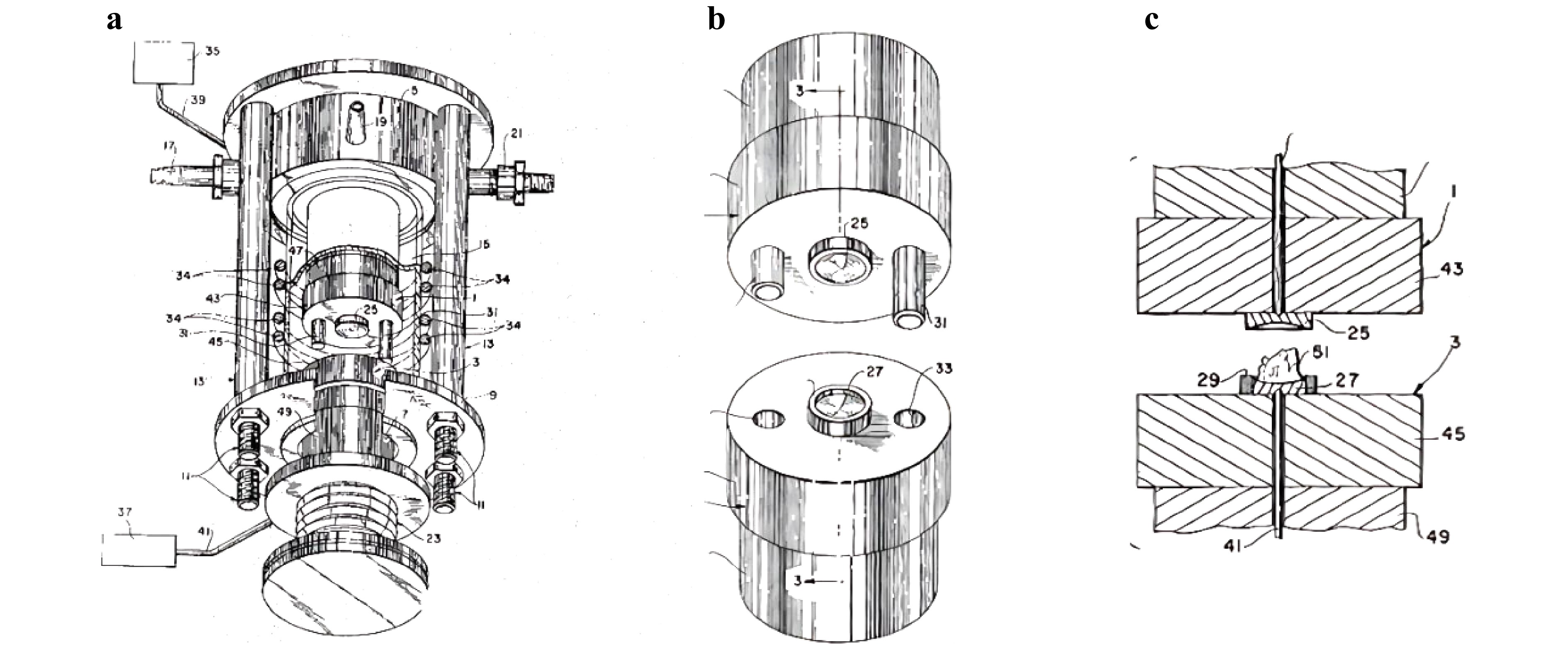
Fig. 4 An early design of glass molding press69. Notice for the glass preform optical finish was not required in the first patented glass molding process design (a small glass pile not a gob or a preform with any regular shapes is placed in the mold cavity). a glass molding press b mold assembly c cross-sectional surface of mold assembly.
• Molding process requires a heating unit to heat the glass to above its transition temperature.
• Optical quality mold inserts and preforms with optical finish are required.
• Cooling takes place immediately after molding but is not considered annealing. For further discussion on cycle time limitations, see Section 2.3.
• Anti-sticking coatings can improve mold life, thus are necessary in high volume manufacturing.
• A considerable amount of volume changes occurs during molding and cooling that can impact future optical applications.
• Heat transfer in glass molding can be very difficult to accurately model due to high precision needed and variances involved in a typical heat transfer process.
-
Molding equipment is commercially available or can be self-constructed. Fig. 5a shows a commercial glass molding press GMP-311V marketed by Toshiba Inc. (now Shibaura Inc.) since the 1990s70. Fig. 5b shows a 170 mm molding press by Moore Nanotechnologies71. Many universities and research institutions have carried out equipment development work73,74. Core elements of the molding presses include heating systems, servo control of position and pressure, and cooling of the mold assembly, usually forced air and nitrogen mixed cooling. Forming of glass lenses is often performed at temperatures over 600 °C, although glasses are chemically stable, most mold materials are not. Therefore, the entire mold assembly (for example, some mold assemblies are shown in Fig.5e, g) needs to be protected either in an inert gas environment or in high vacuum. Vacuum is created in a two-stage operation: first a mechanical pump removes most air from chamber; then a molecular pump reduces the pressure to below 10−6 bar (≈10−6 atm). As we will discuss next in this review, glass property is entirely temperature dependent once the composition is determined. Therefore, a quintessential control steps in a molding system is its temperature control, especially during cooling.
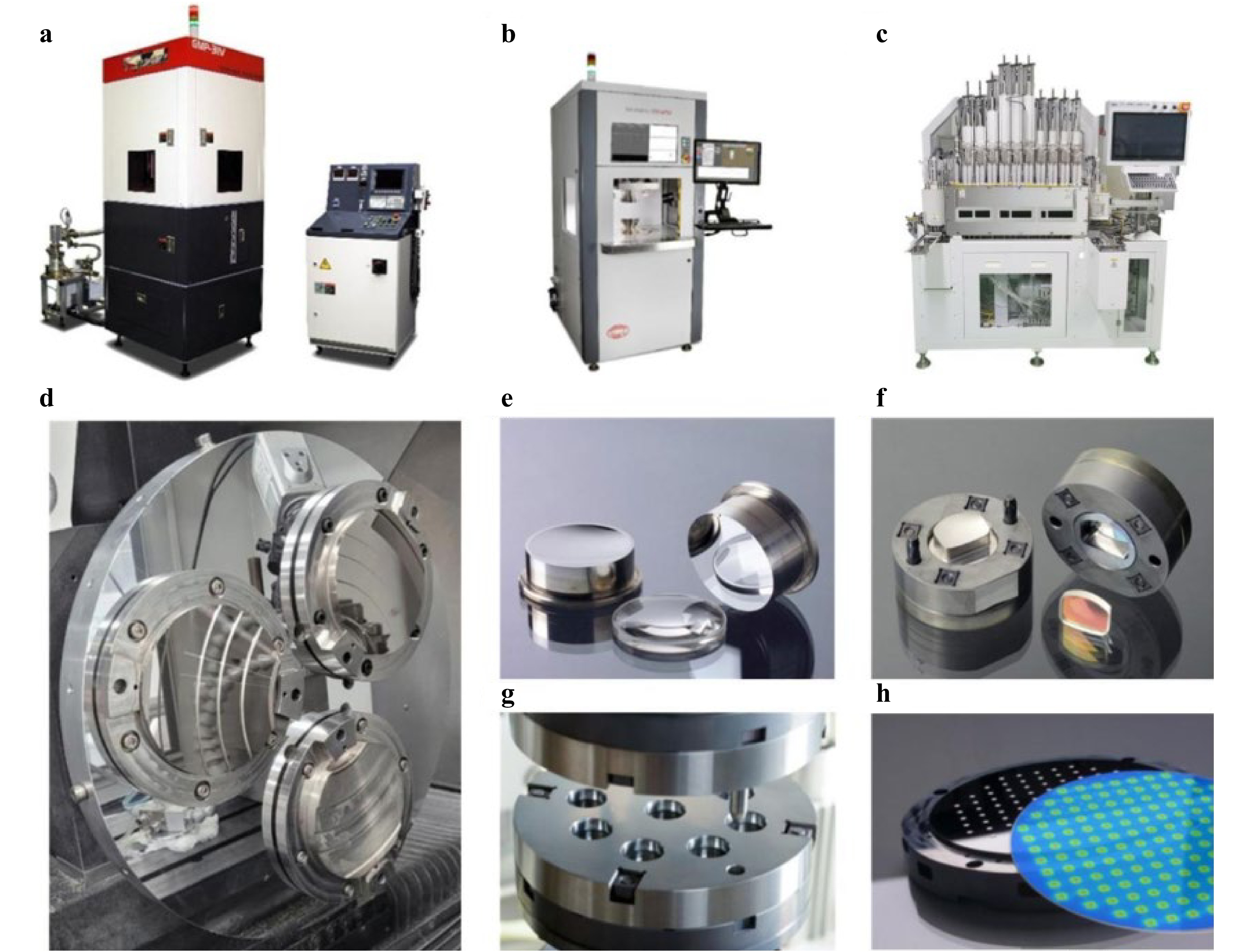
Fig. 5 Molding equipment a GMP-311 from Toshiba70, b 170GPMV from Nanotech71, c multi-stage molding machine from Aachen Technology Shenzhen Co., Ltd, d Mounting of ring segment molds for diamond turning. These mold inserts are nickel plated for optical finish34, e tungsten carbide aspherical lens mold, f freeform lens mold assembly, g Multicavity mold assembly h wafer level mold insert and molded glass. e~h are all from Ref. 43.
Sometimes, to increase production rate, a single molding unit design may not be adequate. As one type of solution, Fig. 5c shows a multistage molding press and Fig. 5f, h show another possible solution, a microlens array mold used in wafer level glass molding (WLG, more discussion will be given in section 6). As aforementioned, a major impediment to production implementation of glass molding process is cost of fabrication. Each approach has its pros and cons. In this review, multistage molding process will not be specifically examined since the focus of this review is on precision optics. In section 6 we will elaborate WLG technology as we believe this process has higher potentials for micro and meso scale (generally regarded as 1 mm to 10 mm) glass lenses as the demands for these optical components in the near future are considered to be the greatest due to explosive growth in mobile devices and onboard camera modules in automobiles. Since glass molding naturally replicates the entire mold surface in a single operation, WLG in principle follows the same path semiconductor industry has been practicing, i.e., increasing wafer size is equivalent to reducing the production cycles (of a single stage molding) multiple times.
A unique nature of compression molding, ironically also its bottleneck in reducing production cycle time is the need to heat up and cool down the entire mold assembly and lenses inside. For small optics, this is not a significant issue but for larger optics, for example, lenses with a diameter of few inches, high thermal mass can render this process completely useless. To this end, in addition to multiple molding units and multiple mold cavity design a third possible alternative exists, a fundamentally different approach, i.e., rapid heating and cooling of mold surface rather than the entire mold assembly using a highly conductive thin film coating. In Section 5, a promising technology based on thin film coating direct heating will be discussed in detail. Because of requirements for high temperature only selected coatings have shown feasibility of direct heating up the glass surface efficiently.
-
Glass properties are predominantly determined by viscosity and viscosity is largely dependent on composition and temperature. To describe the relationship between viscosity and temperature, a popular model is the VFT (Vogel-Fulcher-Tammann equation)75,76:
$$ {\lg}\eta (T,x)={\lg}{\eta }_{\infty }\left(x\right)+\frac{A\left(x\right)}{T-{T}_{0}\left(x\right)} $$ (2) where T is temperature, x is composition, and the three VFT parameters (x, A, and T0) are obtained by fitting Eq. 2 to experimentally measured viscosity data. Other models, such as WLF (Williams-Landel-Ferry) equation, an empirical time-temperature super position equation, is also used often77. Williams, et al. showed that the WLF model has provided a good fit in both the glass transition temperature range and the temperature above77. The WLF model, as an empirical formula for a shift function αT, is expressed as77:
$$ \mathit{log}{\alpha }_{T}=\mathit{log}\frac{\eta \left({T}_{\rm{ref}}\right)}{\eta \left(T\right)}=\frac{-{c}_{1}\left(T-{T}_{\rm{ref}}\right)}{{c}_{2}+\left(T-{T}_{\rm{ref}}\right)} $$ (3) where, c1 and c2 are constants for a selected glass material and can be calculated from glass viscosity values at given temperatures. For example, in thermal slumping of x-ray telescope mirrors, D263 glass78 sheets are thermally warped into high precision reflectors. To model the slumping process, viscosity data can be acquired through WLF model using three discrete data points (Table 2 and Fig. 6 below). Work in polymer rheology has shown that VFT and WLF are mathematically equivalent80.
Viscosity η d·Pas Temperature (°C) Strain point, 1014.5 529 Annealing point, 1012 557 Softening point, 107.65 736 Table 2. Viscosity of D263 glass at different temperature79
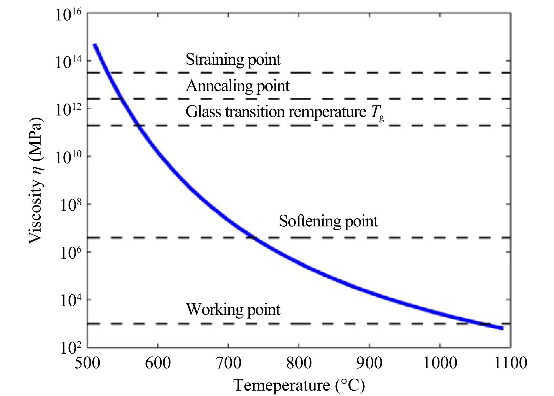
Fig. 6 Fitted viscosity vs. temperature curve of D263 glass using a nonlinear least-squares fitting method based on experimental viscosity data79.
Since glass material properties can only be practically measured at discrete point, measurements of liquid CTEs of P-SK57 and P-LASF47 glasses were conducted by an Orton standard dilatometer at The Edward Orton Jr. Ceramic Foundation (6991 Old 3C Highway, Westerville, OH 4308238). Therefore, for both analytical and numerical simulation, VFT or WLF equations become indispensable to fit the data over the entire temperature range of interest. This relationship demonstrates that glass molding is fundamentally a thermal process, therefore heating and cooling are important features. Requirements for heating and cooling include precision temperature monitoring and control. In addition, as a production tool, shorter cycle time is extremely important. For the major equipment available on the open market, infrared heating appears to be the preferred primary heating elements partially for its fast heating capability.
Most optical glasses are semi-transparent with good absorption (from 0 to 5 μm81,82 and Fig. 7a) but common mold materials, such as tungsten carbide often need more time to heat up and cool down therefore cycle time is normally decided by the thermal properties (capacity) of the mold materials. This remains a major challenge for compression molding as the temperature for both the mold assembly and optical glass needs to be raised and lowered simultaneously since majority of molding is performed as an isothermal process. Time needed for heating and cooling, particularly due to the high thermal mass of the mold assembly, fundamentally limits the production cycle. This bottleneck not only extends the total cycle time but also hinders proper annealing of the glass after molding. Without effective thermal control, internal stresses and property variations may arise. Fig. 8a shows the heating unit on the Toshiba machine. The Dyna Technology press has two 1kW infrared lamps used as heating elements each powered by a separate Watlow solid state pulse width modulated (PWM) power supply.
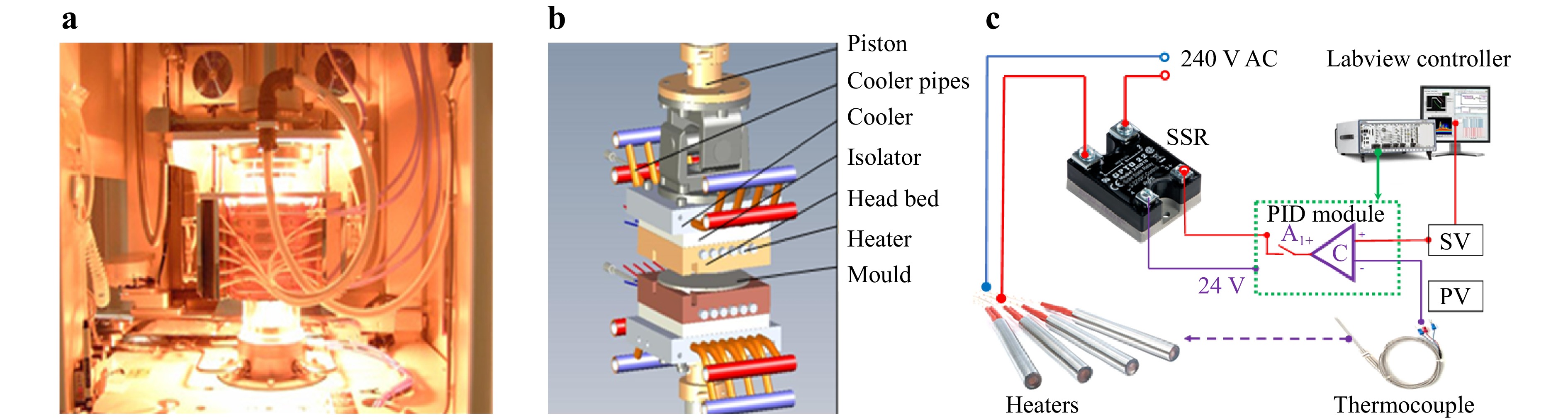
Fig. 8 Schematics of heating systems used in molding presses a Infrared heating85 and b cartridge heating elements83,84. c A solid state relay powered circuit is used to provide current to either infrared or cartridge heaters used in a home built glass molding press (unpublished data). d A snapshot of a LabVIEW VI (virtual icon) loop used to maintain temperature in a glass molding press (unpublished data).
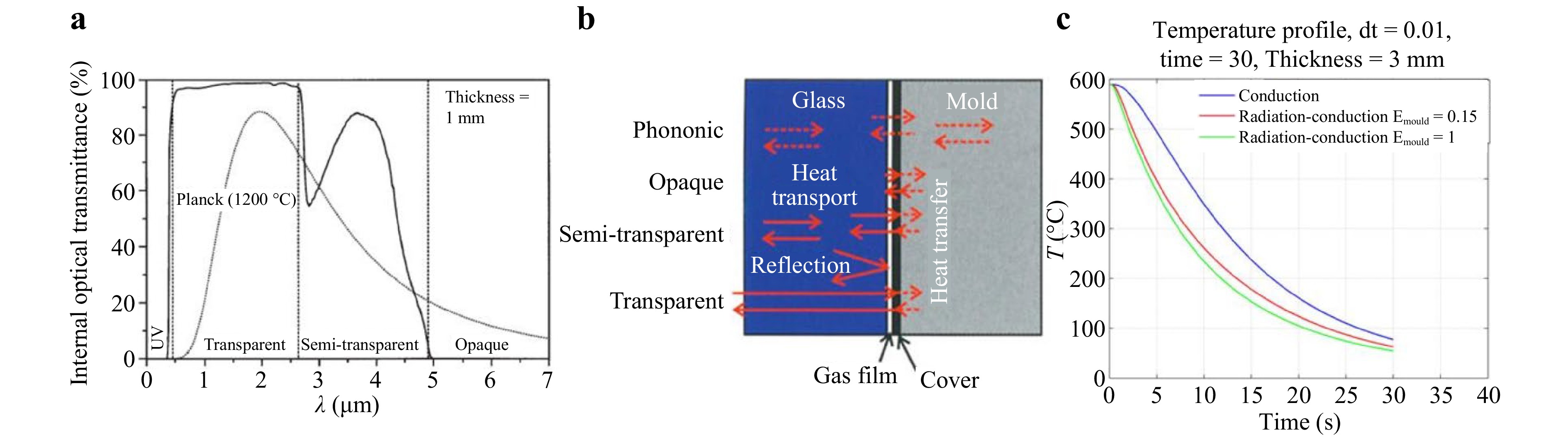
Fig. 7 a Internal optical transmittance of a 1-mm-thick glass pane in the wavelength ranges: UV (opaque), transparent, semi-transparent, and opaque. The dashed curve displays Planck's function at 1,200 °C82 (page 240). b Heat transport in hot glass and between glass and mold, solid arrows indicate radiation heat flow (from Ref. 82, page 239). c a molding experiment where temperature change will be different if radiative heat transfer is included83,84.
Second type of heating elements is group of cartridge heaters design. Fig. 8b shows a customized glass molding assembly83,84. In this design, cartridge heaters are installed in the thick platen next to the mold plate, subsequently, heating of glass will require heat transfer from mold plate where cartridge heaters are installed to mold inserts then to optical glass. Due to large thermal mass of mold inserts, plates and glass preforms themselves, thermal resistances at mold-glass interface, temperature increase and decrease in glass preform/lens can take quite some time and this fundamentally sets the production cycle time limits and cannot be easily changed without major alteration to molding equipment. This situation is in large part directly responsible for slow adoption of this technology in industry. Shortening glass molding cycle whether through reducing thermal mass or installing fast heating and cooling units such as carbide-bonded graphene coatings will prove to be critically important in industrializing the glass molding process86. Molding temperature is controlled in real time using feedback from a thermocouple installed inside a mold insert at a location that is as close as possible to the glass-mold interface to minimize time required for heat flux to flow into or out of glass. Fig. 8d is the feedback loop using virtual instruments (VI) in LabVIEW (unpublished data), used at a home built glass molding apparatus87. In principle, this unit can directly provide power (in the form of current) to both infrared and cartridge heaters, i.e., both heaters are resistant loads. Fig. 8c shows the hardware connection of a typical heating unit consisting of heaters (in this configuration, cartridge heaters), a solid-state relay, a temperature control module and a data acquisition board from National Instruments (NI) to record temperature data and perform control of mold insert temperature.
Unlike machine tool servo control where characteristic time is in the nanosecond or less88, thermal control is dictated by both the slow response time of a thermocouple and more decisively by the time of the heater needed to heat the mold assembly (determined by the thermal mass of the mold assembly) and this time can be excruciatingly long89. This unique feature fundamentally undermines the controllability of glass molding process. Although excessive cycle times require additional energy input, this is less a concern from a cost standpoint than production time. In practice, a step called soaking where temperature of the entire mold assembly is maintained at a constant level is added after mold/glass temperature reaches designated value, to allow temperature to reach a uniform distribution. However, since thermocouples cannot be installed inside glass, direct measurement of temperature within glass is out of the question. Typically, deep holes are drilled inside the mold inserts which allow thermocouples to be placed very close to the mold surfaces. Unfortunately, even with this setup, interior temperature in a glass lens can only be interpreted. Such an arrangement is physically inaccurate and mathematically ill posed90–92. Furthermore, a single thermocouple does not register precise temperature gradient, but multiple thermocouples require the use of a multiple-input-multiple-output (MIMO) control scheme which can be quite complex. Even with just two thermocouples, lower mold always has higher temperature and requires extra power input to balance.
-
Bulk of heat transfer in glass molding take place through conduction and convection in compression molding regardless of the heating elements used93. Heat transfer via conduction is inherently a very slow process, a main reason for long cycle time, i.e., prolonged cooling since coolant lines cannot be installed inside mold assembly like most injection molding due to high molding temperature required for most glass materials. To reduce cycle time, one remedy is to increase input power to the heaters such that temperature can be rapidly increased. For example, a lab compression molding press is equipped with four 1.5 kW Hakko cartridge heaters in top and bottom mold separately, providing total of 12 kW heating capacity74, resulting in extremely short heating time. For cooling, it is however rather difficult to shorten the time required due to high thermal mass. Forced air/nitrogen cooling helps but can result in high level of thermal stresses94,95 therefore cannot be arbitrarily set. This problem can render a molding process prohibitively expensive to run, especially for molding large and thin optics where stress level needs to be controlled carefully to prevent warpage or even fractures96,97.
Conduction is the primary mode of heat transfer throughout the entire molding process. For conduction within the mold or glass lens, heat transfer rate is determined by materials’ basic thermal properties, such as thermal conductivity and specific heat98. Temperature dependence of these properties should be considered for accurate temperature prediction and control99. At the glass-mold and mold-mold contact interfaces, heat transfer occurs via contact conduction. The interfacial contact conduction coefficient is a crucial parameter, but it is challenging to accurately determine this value. Early simulations treated the contact conductance coefficient as a constant value (e.g., 2,800 W/m2·K) borrowed from previous studies on glass panel manufacturing100. Subsequent studies proposed a gap-dependent coefficient model101,102, using the result of the gas medium’s thermal conductivity divided by the gap distance when two surfaces are close but not making direct contact. Later, the complex dependence of thermal contact conductance on mold surface roughness, contact pressure, and temperature, was determined by using infrared thermography method103. During cooling, heat within glass and molds is removed by the forced convection of cooling gas. Especially, the equivalent convection coefficient of glass-nitrogen gas was obtained by using computation fluid dynamics simulation and residual birefringence measurement104.
Radiation is usually ignored in process modeling since it only becomes impactful at temperature over certain level, e.g., above 600 °C and even at this temperature it only roughly accounts for less than 10% of total heat transfer91,105. Previously heat transfer in compression molding of glass lens has been limited to conduction and convection. This simplified approach worked well for conventional lenses where diameter and thickness are relatively close. Preliminary analysis using FEM (Finite element method) software however indicates that a thin glass lens may experience large shape change due to radiation82–84,105. This impact is especially noticeable in large and thin glass lenses. and accurately predict radiation in compression molding at elevated temperature is critical to understanding the process and ultimately controlling the process92. Fundamentally, heat transfer inside glass is a combined effect of photonic and radiative heat transport as shown in Fig. 7b82. Between glass and mold heat transfer takes the form both by conduction and radiative portion due to interaction between heat radiation from interior of glass and the mold surface. Physically, a typical forming process involves both pressure and heat. Sometimes, cooling starts before pressure was released resulting in different volumes in finished products. Fig. 7c shows the temperature profile of a glass molding process with and without considering radiative heat transfer through numerical simulation83,84. A vast amount of research using experimental, analytical and numerical approach has been performed for many decades to study and characterize the heat transfer mechanism both within glass and across the glass-mold interface82,92,105–108. The models developed in conjunction with these studies generally employ 1D (one dimensional) numerical algorithms with simplified radiation models to represent heat transfer in glass and at the boundaries. While these models have provided a great deal of information concerning glass-mold heat transfer, their applications to real practical problems require careful consideration of all heat transfer mode including accurate formulation of radiation as discussed in the references above.
-
In high volume optical manufacturing, mold making is one of the most critical steps. It is a general consensus and also confirmed experimentally that mold surface determines the quality of glass lens final surface finish and geometry108,109. As such in manufacturing aspherical glass lenses by molding, first step is to create a high-quality optical mold surface. Since molding is performed at high temperature mold materials need to be chemically inert and mechanically rigid. This requirement excludes much of the common engineering materials that can be easily machined by single point diamond turning, leaving grinding as one of the few feasible mold making processes. Although lower temperature moldable glasses (for example, P-SK57 and F-LASF 47 from Schott and L-BSL 57 from Ohara, Tg ~ 500 °C) are available, these glasses appear to have lackluster market reception probably due to the specific ingredients used to manufacture these materials inadvertently limited the performance of molded glass optical lens. Ultimately, design and fabrication of glass mold inserts will need to work with most glass materials, especially glasses that manufactured in large quantity such as N-BK 7 (Tg 557 °C, molding temperature ~685 °C) rather than just a few moldable glasses. Most low temperature glass materials tend to have high coefficient of thermal expansion (CTE) making handling tricky and often a very difficult task.
-
Fabrication of diffraction limited precision glass lenses using compression molding process has been demonstrated72,108. However, production runs using the glass molding process require that the molds be fabricated with a small amount of offset from the design curve in order to compensate for the lens (thermal) shrinkage incurred during annealing. This procedure, also known in industry as (mold) iteration, needs to be repeated until the molded lenses meet manufacturing specifications110. Mold iteration refers to the iterative adjustment of the mold geometry to compensate for thermal shrinkage of the glass during cooling, thereby achieving dimensional accuracy in the molded lenses. A typical glass molding process may need two or more iterations27,110. Materials for glass molds should have high hardness, heat resistance, and chemical stability101,111. These materials include WC, SiC, AlN, TiN, Al2O3, and TiC. Due to the extremely high hardness (e.g., Rc > 90 for WC) of these materials, processes to fabricate these molds can be expensive and difficult to control112,113. Although glass molding is a low-cost mass production process, mold making however can be a difficult and expensive undertaking. Therefore, process modeling and numerical simulation become central for glass molding’s implementation in industry to minimize work needed for mold preparation and restoration when repair is needed.
Historically, optical fabrication requires grinding and lapping with loose abrasives (Fig. 9a, b), followed by polishing to remove the grinding tool marks114,115. It is a repetitive process which continues until the optics meet the desired specifications. Frequent tooling inspection is also required during polishing to ensure good curve conformance. This strategy does not work well with aspherical surfaces in which a long polishing cycle not only increases product cost, but it can also cause figure degradation since a polishing process naturally tends to make the optical surface into a spherical shape. The common grinding setups including cross axis grinding and titled setup are presented in Fig. 9d. A famous example is the fabrication of the Hubble primary mirror. After initial grinding, and polishing, the test and evaluation phase reduced the initial figure error of 2 waves (1.3 microns) to just 0.1 waves (0.06 microns) peak-to-valley across the entire mirror surface. The average time for each polish/test cycle was six days. Total accumulated real polishing time was just 74 hours though116. To reduce cost and improve optical quality major efforts in the past several decades have been dedicated to improving the polishing process for aspherical surfaces.
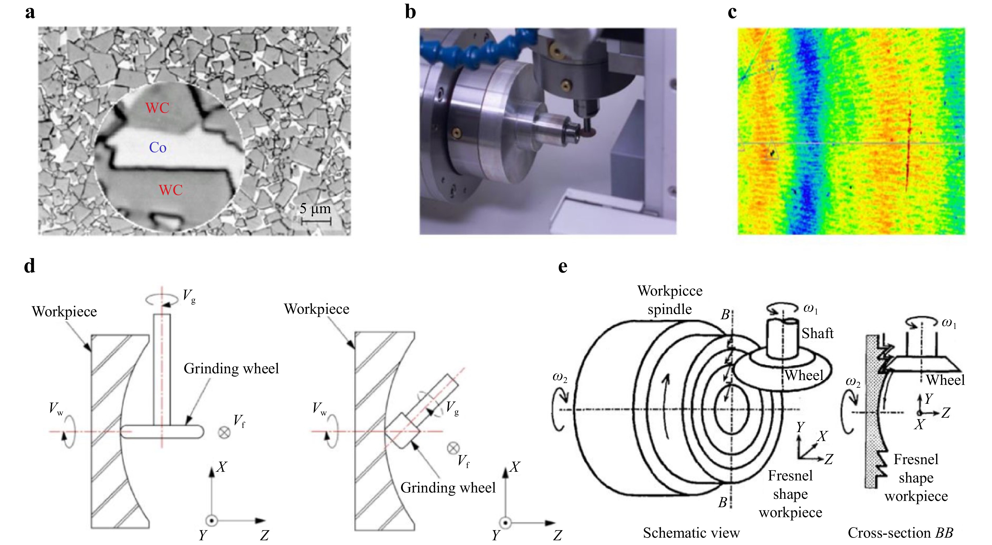
Fig. 9 a Microscopic photo of binderless tungsten carbide mold surface. Notice the existence of cobalt matrix albeit at minimum119, b Ultraprecision grinding of a tungsten carbide mold using Toshiba ULG grinder and a high speed air bearing spindle, c White light interferometric measurement of a ground surface of a binderless tungsten carbide mold surface-unpublished data. On the mold surface grinding marks are still visible, in the scan area peak to valley is approximately 5 nm and arithmetic average Ra is 1 nm, d Two common grinding setups: cross axis grinding and titled setup120, e Ultraprecision grinding of a Fresnel tungsten carbide mold insert using a profiled grinding wheel118.
For large glass diffractive lens mold, grinding is difficult due to excessive bond wear117. However reports of meso scale diffractive lens mold fabrication by ultraprecision grinding using sharp edge grinding wheel demonstrated a valid process for glass molding with micro and nanometer scale features118 (Fig. 9e). In most recent publications on glass molding, mold fabrication is usually carried out using conventional grinding and polishing process without additional investigation. In this review, a few possible alternatives are reported. These are processes based on unique applications of lasers and coatings. The overarch goal of these processes is to replace time consuming grinding and polishing processes. Special grinding configuration can also be used to fabricate cylindrical lens array113,118. It has long been known that CVD SiC is probably the best available mold materials. As demonstrated in some archival work121,122 optical finish can be achieved either directly or with post grinding polishing using automated processes such as magnetorheological polishing or strict mechanical polishing123. However, industry appears to have accepted a somewhat easier to process alternative in tungsten carbide (binderless-hot pressed but highly compact structures) at the present.
-
Conventional mold fabrication with precision grinding is efficient but difficult to control and time consuming. It is a compromise among production speed, precision, and surface contour. Due to the grinding tool size limit and diamond grain size limit, small curvature concave molds are difficult to machine. Furthermore, smaller grits produce better surface roughness but accompanied with slower speed and more bond wear thus less control on optical surface contour. Often grinding marks cannot be completely removed for fear of changing the base curve (Fig. 9c) clearly showing the grinding marks. The following processes demonstrate great potentials as alternative solutions to mold making with different degrees of success. Fig. 10 summarizes these mold fabrication processes with laser assistance, thin film coatings or simply different mold materials.
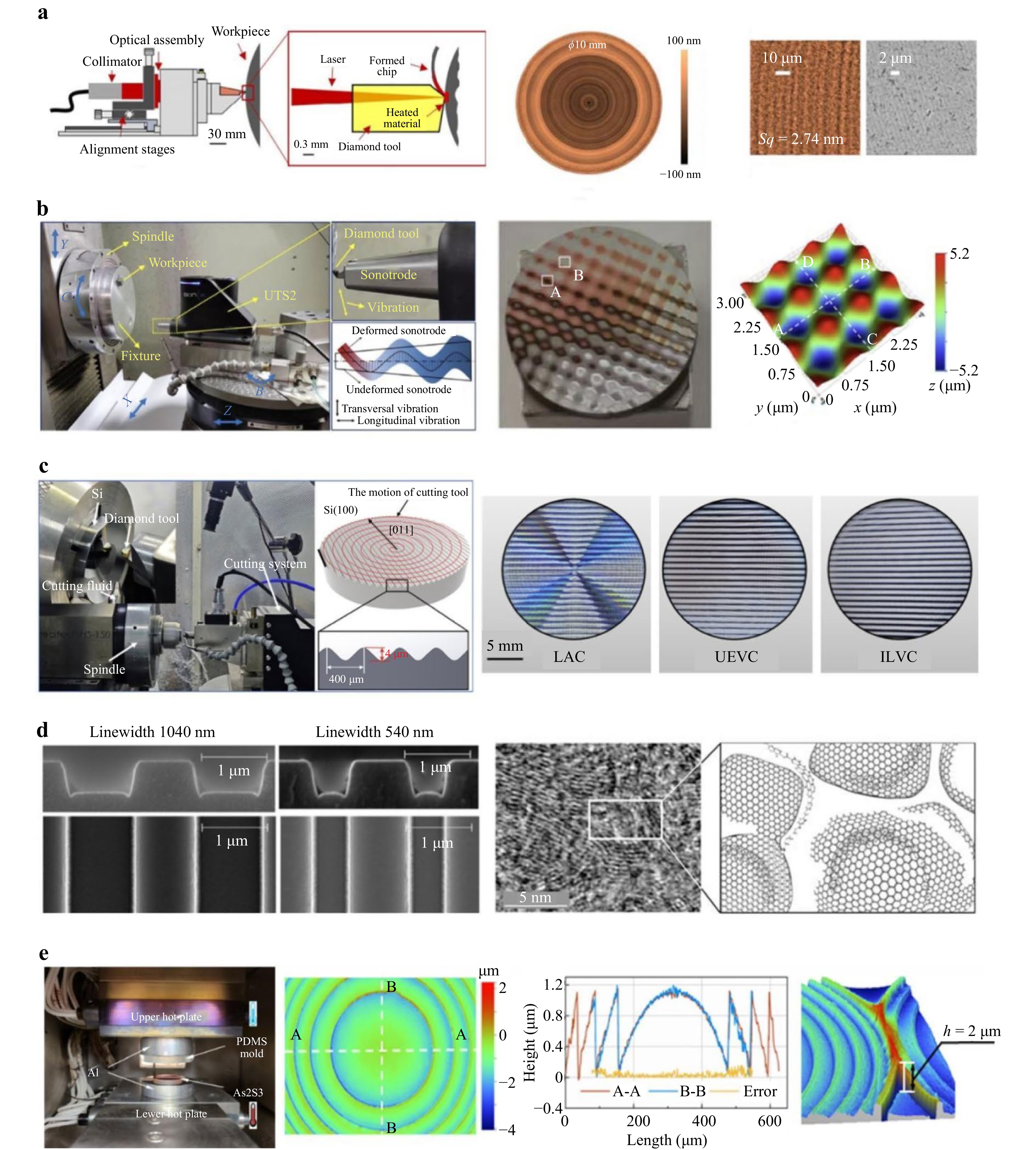
Fig. 10 a μ-LAM process including Optimus T + 1 tool post, schematics of the tool-workpiece-laser light interaction and Fizeau interferogram, SWLI interferogram and SEM image of WC124, b Ultrasonic vibration-assisted cutting process and machined sinusoidal grid125, c Experiment set up of sine-wave structure manufacturing of silicon and machined workpieces by different cutting technologies. The workpieces are machined with laser assisted cutting, ultrasonic elliptical vibration assisted cutting and in-situ laser-vibration hybrid assisted cutting respectively126, d SEM images of glassy carbon mold with depth 485 nm. Top images correspond to side view cuts of the bottom images127. e Step-and-repeat hot imprinting and non-isothermal glass molding process by employing a soft PDMS mold87.
-
Preferred glass mold materials include many super hard materials therefore diamond turning cannot be used due to high wear rate. Diamond turnable materials that are familiar in commercially available sources have relatively low melting temperature. For example, electroless nickel phosphorus plating specifically designed for diamond turning cannot sustain the temperature necessary for glasses such as BK 7 (around 685 °C). To overcome this issue, glass manufacturers developed special glasses with lower transition temperatures. In the open market, Schott has several moldable glasses, P-SK 57 (Tg = 493 °C) P-LASF47 (Tg = 530 °C) and Ohara produces L-BAL 42 (Tg = 506 °C) and L-BSL 7 (Tg = 498 °C). In addition to electroless nickel phosphorus plating, copper nickel alloys were also tested as possible mold candidates with limited success36,128. One area where diamond machining has advantage is the mold fabrication for diffractive34 and other mold surfaces with complex and small features129. because ultraprecision grinding can be difficult to work with using very small radius tools due to excessive wear.
Grinding process can machine diffractive features but cannot be used for large diffractive surface due to excessive wear of the grinding wheels118. Due to high temperature nature of glass molding, single point diamond machining does not appear to be a good candidate for glass materials with transition temperature over 600 °C at the moment. To our knowledge, there is no diamond turnable material that can handle this temperature. One possible process utilizes a laser to heat up the mold material before diamond tool makes contact with a mold surface. This process is being commercialized by μ-LAM130. The tool post illustrated in Fig. 10a holds the optics needed to focus laser light with wavelength of 1,064 nm at the cutting edge of a single crystal diamond tool. Shown in the figure, laser beam of 1,064 nm enters the diamond crystal and focuses on the cutting edge of the diamond tip area and subsequently laser beam’s energy is absorbed by the workpiece and the accumulated energy will raise the workpiece temperature to the point that machining is being carried out in plastic regime. The heating of the workpiece drastically reduces its hardness resulting in very low cutting forces and therefore improving wear on the cutting edge. This is significant since the cutting edge can be as small as 20 nm131,132. Also shown in the cutting setup a very large negative rake angle is used in laser assisted machining, up to −45° in machining of single crystalline silicon133 or even −75° in machining of single crystalline germanium134.
This process has a promising future for glass molding. For example, utilizing this technology, tungsten carbide (WC) mold can be machined directly in ductile regime with minimum surface and subsurface damages. Using a patented design, μ-LAM process was used to machine a concave WC sample with a 10 mm diameter and ROC (Radius of curvature) of 10 mm. Spindle speed of 2,000 rpm, DOC (depth of cut) of 2 μm, and feedrate of 1 μm/rev was used. The laser power at the cutting edge was 7 W. This is believed to be a feasible solution for reliable glass mold fabrication, especially for micro and meso scale mold fabrication where lenses maybe diffraction limited, i.e., surface finish requirements will not be as stringent as large aperture lenses (e.g. single reflector camera lenses). Tungsten carbide inserts maybe directly diamond machined without or with very minimum post machining polishing using laser assisted process. Since workpiece material is instantaneously heated to well above ambient temperature, material properties such as hardness is significantly reduced, this results in drastic reduction in cutting forces overcame the wear issue encountered in either direct machining135 or with an ultrasonic assisted device136. We believe that direct diamond turning of tungsten carbide or other hard to machine mold inserts combine with small lens apertures, for example, meso scale lenses used in mobile applications where lenses are close to diffraction limit could be a real solution for mold making moving forward.
-
It has been demonstrated repeatedly that single point diamond turning of silicon to mirror surface finish is feasible137,138. However, silicon surface cannot be used directly as mold surface due to the phenomenon called anodic bonding, i.e., at an elevated temperature, chemical affinity between silicate glass and silicon atoms can result in strong chemical reaction and often used in semiconductor industry to bond different layers. A manufacturing process to create graphene like coating on silicon surface will be discussed in section 5127 and references therein. Although graphene like coating can be used to function as an interface layer between mold and glass material, its ideal applications may lie in a fundamentally different direction, i.e., as a solution to reducing prolonged cycle time, graphene like coating can be used as a heating element to directly heat up plastic139 or glass140, significantly reduce molding cycle as the bulk of heat generated by the carbide-bonded graphene was used to soften plastic or glass rather than the entire mold assembly. For micro, meso scale optics as well as wafer level glass molding (discussed in section 6) direct heating is a promising technique that can fundamentally change the aspherical glass lens manufacturing as we know it.
-
As shown in Fig. 10b, c, another technology that based on single point diamond turning process to achieve fabrication of a variety of difficult-to-machine mold materials utilizes ultrasonic vibration141. Vibration assisted machining process applies a certain frequency of micron amplitude on the machining tool to realize the periodic change of the relative position between the tool and workpiece, thereby reducing cutting force and temperature at interface142 and surface roughness, improving stability of the process system and tool life143,144. By adopting ultrasonic vibration, smaller amount of material removal per vibration cycle (cutting stroke less than 800 nm) under relatively low nominal cutting speeds (normal cutting speeds below 5 m/min) can achieve optical mold surface with hardly any tool marks or brittle fractures145. In addition to cutting, ultrasonic vibration assisted grinding and polishing also prevail over conventional grinding or polishing for difficult-to-machine materials in terms of high form accuracy and low surface roughness146,147. When machining an optical structure such as a microlens array, even though overcutting of the tool edge may lead to form error between the designed and machined microlens array, resulting in increasing or decreasing lenslet sag, surface roughness and form accuracy of the microlens array still meet the requirement of the optical application because reduction of material adhesion and tool wear in ultrasonic vibration assisted cutting can compensate for the error to some degree148. Brittle and hard materials are specifically suitable for ultrasonic vibration machining144. Tungsten carbide (WC)149, silicon carbide (SiC)150, zirconia ceramics151, and single-crystal MgF2152 and sapphire153, are all mold material candidates that can benefit from this process.
-
In addition to popular mold materials mentioned here, i.e., tungsten carbide, nickel phosphorous plating and silicon, other materials considered for glass molding include glassy carbon and many other materials, especially for micro and nanoscale optical and photonics devices37,154. Experience indicates glassy carbon (wafer) appears to be superior to many peers and will be discussed briefly as this review is primarily focused on imaging optics. One unique use of glassy carbon is to build mold inserts for super high temperature molding of fused silica where molding temperature can reach 1,500 °C as glassy carbon remains the only possible candidate for this purpose155. Shown in Fig. 10d is a glassy carbon mold that was etched to create microfeatures. For example, microstructures consist of sp2-hybridised carbon layer were experimentally observed156 and similar results also reported somewhere else, e.g.157 and158. This type of surfaces inherently have high thermal conductivity, high electrical conductivity, and low friction. Although this mold material is quite unique in that high durability and high temperature capability are expected ceramics nature of this material means it cannot be diamond machined especially molds for large size glass optics. Although it does not have high hardness, diamond turning tests have shown that fractures can form both on both diamond tools and mold surfaces so we believe that glassy carbon has to be precision ground and then polished if used for aspherical lens mold. Together with high cost of the material, this presents a significant setback for glassy carbon as there are other mold materials readily available in industry that are more economically available.
-
The limitations of the hard material mold in machining discussed above, in principle, can be avoided by using soft material molds159,160. Recently, PDMS, one of the soft material molds, was used as mold for precision molding for its simple, mature, and low-cost manufacturing process, as well as the flexible mechanical properties161,162. Compared with hard materials, PDMS has the following advantages as a mold: (1) PDMS can be easily obtained over large areas with good reproducibility, and high accuracy, by casting a liquid onto a master substrate followed by thermal curing. (2) PDMS has low surface energy, which promotes separation from the workpiece, and prevents damage to the workpiece during separation stage. (3) It has high manufacturing efficiency and low cost163. Although PDMS does not appear to be capable of using as regular glass mold inserts directly, we believe that combining PDMS mold with special glass materials such as sol gel glass can be a very attractive and practical solution to making aspherical lenses, especially for lenses that are suitable for consumer electronics such as cell phone cameras.
At present, PDMS as a precision mold encounters some problems, especially the rigidity of PDMS. PDMS is softer than that of optics material at room temperature, and its hardness decreases with the increase of working temperature. To overcome the difficulty of insufficient rigidity of a soft PDMS mold, a non-isothermal molding method makes it possible to transfer microstructures from the soft mold (PDMS) to hard substrate (As2S3 glass) with high fidelity87,164. Shown in Fig. 10e, a square 30 × 30 infrared Fresnel lens arrays on chalcogenide glass were successfully obtained. The entire process time of the non-isothermal molding is less than 15 min (including heating for 2 min, soaking for 4 min, pressing for 5 s, and cooling for 8 min). It is five times more efficient than the conventional molding process and can be further shortened with more process improvements. Although the rigidity of soft mold can be improved, the soft mold becomes less a solid with the increase of molding time and heat accumulation. PDMS molds are currently only used in the molding of low-temperature optical materials and the molding of micro-nano structures. Molding processes of optical glass with higher melting point need further investigation165.
-
In a molding process, because of high temperature involved, glass has to be heated inside a vacuum chamber to a temperature higher than its transition temperature (Tg)108. The glass blank is then pressed between the molds at a temperature above its transition temperature but below the working temperature. The formed lens will remain in the molds for cooling process to complete. Fig. 11 is a schematic showing a generic glass molding machine design and molding at different stages. During the annealing stage the two phenomena that become important are the interface heat transfer between glass and mold which could be a combination of conduction and radiation and structural relaxation of glass material due to its viscoelastic nature in the transition zone. This section is divided into four subsections to cover each of the above-mentioned phenomena in greater detail. One of the aims of this review is to summarize and characterize each of these phenomena and their relevance to different lens molding stages.
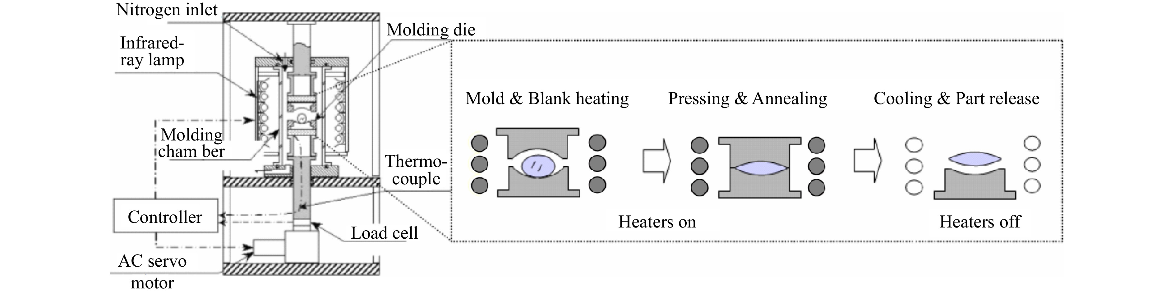
Fig. 11 Precision glass lens molding machine and a generic molding process108.
-
Fig. 12 is a schematic of mold temperature and mold position for a generic glass molding process. The solid (red) line represents temperature changes and the dotted (blue) line indicates the position of the lower mold during a glass molding cycle. A typical glass molding process can be grouped in three different stages, labeled as stage A, B and C. In stage A, N2 flows through the mold assembly area to purge the chamber. The mold assembly and the glass gob are heated to a temperature slightly higher than the transition temperature of glass. In stage B, molding of the glass lens takes place at a constant temperature. In stage C, heating is turned off and N2 flow rate is increased to accelerate the cooling of the mold assembly and the finished lens is released at a temperature close to room temperature.
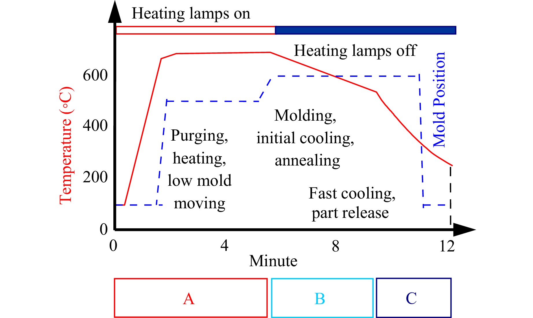
Fig. 12 Precision glass lens molding machine and the molding process108.
Typical compression molding of glass lenses relies on isothermal heating and cooling processes, wherein pressing into designed shape occurs after the entire glass preform attains the mold temperature. As presented in Fig. 8, conventional precision molding often uses electric heating rods and infrared lamps as heat sources108. In a typical hot embossing machine, heating rods are embedded into the heating plate where mold assembly with glass inside can be placed on its top and heat will be transferred to mold assembly directly by thermal conduction. As for infrared lamps, they are usually symmetrically installed around mold assembly to heat the entire mold and glass by thermal radiation. In both heating strategies, nitrogen flowing in the chamber will also bring heat to mold and glass by thermal convection. Despite employing the same heat source to heat both the glass preform and molds simultaneously, obvious delay in temperature rise happens within the glass preform due to different heat absorption rates of glass and hard mold materials including silicon carbide (SiC), tungsten carbide (WC), and fused silica54. Heat transfer at the glass-mold interface is a transient phenomenon and its value may depend on interface pressure, mold surface roughness, and the difference in temperature of the two contacting bodies, which largely impacts the final shape and optical performance of molded lenses.
Although the molding technology is precise and reliable, simple and easy to use, the conventional precision compression molding cycle is generally up to 30−50 minutes108. Especially for ceramic material molds with large heat capacity and low thermal conductivity, the heating and cooling rates are very slow, which will further increase the time of a single molding cycle. The long process cycle not only restricts production efficiency of molding technology, but also increases production cost, which makes molding technology unable to meet the growing demand of micro-optical components, and weakens the competitiveness of the technology in the micro-optical component market.
-
For imaging applications, glass and plastic are both primary material selections. Materials for other wavelength applications though may have substantially different requirements on materials. For examples, UV lithographic lenses almost entirely consist of fused silica glass as most conventional glass materials do not have the properties for short wavelength transmission. On the other side of spectrum though, materials such as silicon, germanium or many chalcogenide glasses have to be used since most silicate glasses are not transparent to long wave infrared light166. For the purpose of this review, we focus on silicate glasses, e.g. glasses like BK 7 and some specially formulated low temperature glasses, P-SK57, P-LASF47, L-BSL 7. These materials’ mechanical and optical properties are summarized in Table 3.
Material Properties P-SK57 P-LASF47 L-BSL 7 BK7 Elastic modulus, E [MPa] 93,000 120,000 82,500 82,500 Poisson’s ratio, ν 0.249 0.298 0.206 0.206 Density, ρ [kg/m3] 3,010 4,540 2,510 2,510 Thermal conductivity, kc [W/m °C] 1.01 0.85 1.1 1.1 Specific heat, Cp [J/kg °C] 760 550 858 858 Glass transition temperature, Tg [°C] 493 530 497 557 Softening temperature, [°C] 593 627 593 719 Solid linear CTE, αg [K−1] (20-300 °C) 8.9 × 10⁻⁶ 7.3 × 10⁻⁶ 8.3 × 10⁻⁶ 8.3 × 10⁻⁶ Glass mataerials are used to in precision optics, architecture, transportation, medicine, energy and scientific exploration. Historically glass has been a very mysterious materials169. Unlike most engineering materials such as metals and ceramics, glasses are best known for not having any long-range structures. Such existence appears to violate thermodynamics because glass never reaches thermal equilibrium. In another word, property values (e.g., volume or enthalpy) of a glass depend on the thermal history experienced by the system and are therefore cannot be determined by temperature T and pressure P. Additional state variables are need the describe macroscopic state of glass to include the impact of thermal history75,170. One way to understand this fundamental glass mechanism is to utilize the concept of fictive temperature. As Tool suggested to consider glass as an equivalent liquid (naturally at thermal equilibrium) at a higher temperature, denoted as Tf. Glass structures are determined by this “fictive” temperature. This is the fundamental reason that glass deformation during cooling can be precisely modeled (Eq. 5-12), established the scientific foundation for precision glass molding.
How we predict and compensate for deviations resulted from this minute “extra” energy trapped in molded glass lenses are the core content of this manufacturing process. Although glass solid is never in thermal equilibrium, its structures however demonstrate surprisingly high repeatability when temperature decreases, a highly favorable condition for precision lens fabrication subject to precision control of heating especially cooling of the optical glass. Experiments also shown that a viscosity on the order of 1017–1018 Pa s in glass, that glass would not change shape appreciably over even large periods of time76,171 making glass an excellent materials for optical applications with exceptional stability as compared to almost all other materials. The physiochemical condition or state of a glass is reasonably well known only when both the actual temperature and that other temperature at which the glass would be in equilibrium, if heated or cooled very rapidly to it, are known. Again, this latter temperature has been termed the ‘equilibrium or fictive temperature’ of the glass.
Glasses have non-crystalline structures and are often referred to as amorphous or glassy materials although strictly speaking these two terms are not completely equal172. Nevertheless, glass behaves as a pure solid at room temperature but lacks toughness. For example, BK 7 glass, its fracture toughness K ~ 2GPa due largely to microcracks in the glass173. Together with high hardness and high Young’s modulus the so-called critical depth of cut (Eq. 3) for most glasses is on the nanometer range making grinding with super abrasive the only possible manufacturing process. Available grinding process includes grinding, lapping and polishing all require precision machinery and slurries and polishing compound. Mild aspherical can be processed in very low volume but large sloped aspherical lenses and high-volume production will not be feasible with this process. This leaves thermal forming of glass aspherical lenses the only possible alternative.
$$ {d}_{c}=0.15\left(\frac{E}{H}\right)\left(\frac{{K}_{c}}{H}\right)^{2} $$ (4) Where E is Young’s Modulus, H is hardness and Kc is fracture toughness. For example, for glass material BK 7, dc is 6 nm, but a different optical material such as chemical vapor deposition silicon carbide (CVD SiC) can have a value as high as 180 nm. It has been shown that mirror surface finish can be fabricated using microgrinding process without loose abrasive polishing10.
For manufacturing process, volume is an answer for affordability. Unlike crystalline materials, glasses experience glass transition thus can be thermally formed into final shape, this is the fundamental basis for thermoforming precision optics. Since a non-crystalline structure material does not reach thermal equilibrium therefore the mechanical properties of formed optics are always determined by precisely the history of cooling. This very nature of glass materials sets the foundation for glass molding process monitoring and control.
-
In the transition zone the glass materials during and after external press being released will experience stress relaxation. However, at high temperature the viscosity of glass becomes very low resulting in very short relaxation times (on the order of a few milliseconds or even shorter) and the glass flow behavior under these conditions can be described as that of a Newtonian fluid but more often described as viscoelastic170,174. Around glass transition temperature glass materials properties experience slow transition rather than sudden melt. Standard one degree of freedom model can be used to model stress relaxation, but majority of glassy materials are complicated and to precisely model stress and stress relaxation, extra degree of freedom models have to be used. For a typical molding process, relaxation time is in the millisecond range therefore, stresses will quickly disappear, but material flow will be different pending on temperature distribution, forming speed, friction between mold and glass. In a typical glass molding process, forming is usually completed in a few seconds and relaxation only takes a few milliseconds or less resulting in a stress-free status after a brief temperature holding or soaking. Glass has no memory of any stresses after pressing and before cooling starts.
Stress relaxation is a key phenomenon in precision glass molding, especially during the transition from the forming to the cooling stage. Near the glass transition temperature (Tg ), glass exhibits significant viscoelastic behavior—its mechanical response depends on both stress and time. Accurate modeling of this behavior is essential for simulation-based quality prediction, particularly for forecasting residual stress, optical figure distortion, and birefringence in molded lenses. To model stress relaxation, the generalized Maxwell model is widely used, which describes the stress-strain relationship in the time domain using a Prony series:
$$ \sigma \left(t\right)={\int }_{0}^{t}G(t-\tau )\frac{d\varepsilon \left(\tau \right)}{dt}d\tau $$ (5) where $ \sigma \left(t\right) $ is the stress, $ \varepsilon \left(t\right) $ is the strain, and $ G\left(t\right) $ is the relaxation modulus defined as:
$$ G\left(t\right)={G}_{\infty }+{\sum }_{i=1}^{N}{G}_{i}{e}^{-t/{\tau }_{i}} $$ (6) In this formulation, $ {G}_{\infty } $ is the long-term (equilibrium) modulus, $ {G}_{i} $ are discrete relaxation moduli, and $ {\tau }_{i} $ are the corresponding characteristic relaxation times. These parameters can be experimentally determined through stress relaxation or dynamic mechanical analysis (DMA).
Since the viscoelastic response of glass is strongly temperature-dependent, time–temperature superposition is applied to describe the thermorheological behavior of the material. The reduced time tr is calculated using shift factors derived from either the Vogel-Fulcher-Tammann (VFT) equation (see Eq. 1) or the Williams-Landel-Ferry (WLF) equation (Eq. 2). These shift functions enable the transformation of viscoelastic parameters across different temperature regimes.
By incorporating these viscoelastic constitutive models into finite element simulations, it becomes possible to accurately predict stress evolution during molding and cooling. This predictive capability is crucial for process optimization—allowing engineers to fine-tune pressing force, temperature dwell time, and cooling rates to suppress residual stresses and preserve lens geometry. Therefore, the use of these models is not only of academic importance but also central to the reliable industrial implementation of precision glass molding.
-
Zachariasen’s research (Fig. 13a) suggested the existence of nanometer crystalline structures but with a randomly formed network in glass175. The small magnitude of short-range periodic features of most glasses falls far below the wavelength of visible light therefore making glasses idea materials for optical applications178. However, in manufacturing lack of periodic structures prevents glass from reaching thermal equilibrium in reasonable amount of time (Fig. 13b) and is the fundamental mechanism responsible for property changes during molding process. This nonlinear and path-dependent nature implies that predictions of glass properties during molding are often phenomenological in nature, as a fully unified theoretical framework is still under development. Nonetheless, these behaviors remain consistent with fundamental physical principles.
-
Unlike crystalline materials, microscope of status of glass cannot be precisely defined by temperature and pressure along, details of fictive temperature and its relationship to glassy state can be found in numerous publications (e.g.,75,170,179 and references therein). The fictive temperature is typically implemented in modeling via the Tool-Narayanaswamy-Moynihan framework to capture structural relaxation during cooling, enabling accurate prediction of residual stress and refractive index variations. The structural response of glass to a step change in temperature is inherently non-linear and depends on the magnitude and direction of the step change. The non-linearity occurs because the changing structure alters the viscosity and hence the rate of relaxation, as illustrated in Fig. 14a, b170,176. Fig. 13c shows a plot of a temperature dependent specific volume of a liquid being cooled at some finite rate. At the melting point a non-glass forming liquid readily freezes into a crystalline solid (shown by line AE). However, in a glass forming system the melt cools down below its solidification temperature into a metastable state. In the liquid state the viscosity of glass is so low that the structure changes in step with temperature and the equilibrium structure is attained almost instantaneously. As the temperature is lowered further the viscosity of the liquid gradually increases along with the time required to attain a new equilibrium configuration. This results in the deviation of the cooling curve from the equilibrium line AB until the structure is finally frozen in a fixed configuration at point C. This state is called the glassy state since it possesses the rigidity of a solid but has a liquid like internal structure. The temperature interval, TU-TL corresponding to the segment BC, between the liquid and the glassy states is called the transition zone and can be defined as the range of temperatures where the approach to equilibrium takes a finite, experimentally measurable time. In the transition region response of a property to a step change in temperature from T1 to T2 is written as170:
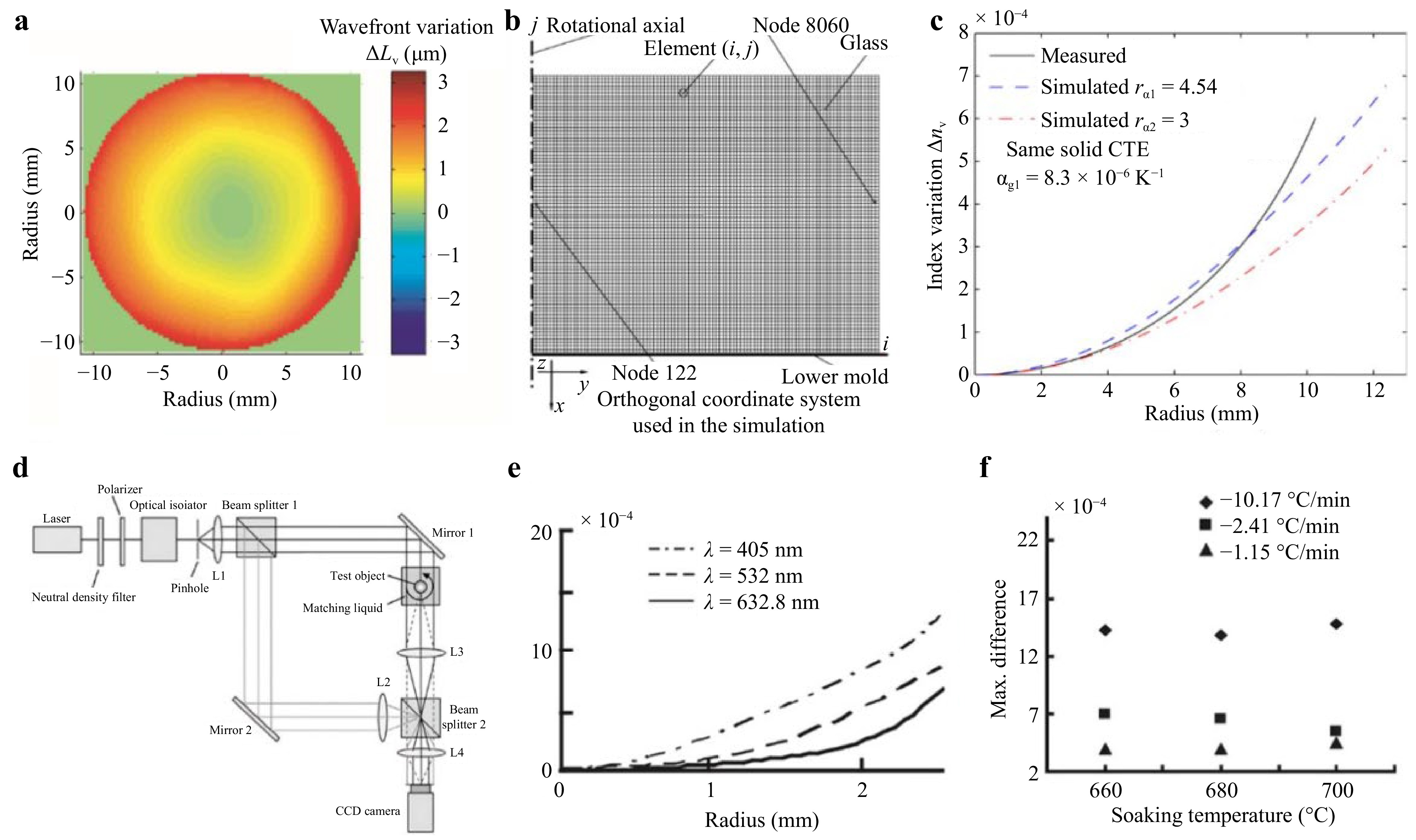
Fig. 14 FEM model for index variation study a index variation measured176 and b FEM mesh of the lens molded176. c Simulation with measured CTE of a solid glass167. d A Mach-Zehnder interferometric setup for index measurement180. e Measured refractive index variations for different wavelength light and f max index changes at different cooling rate for different wavelengths180.
$$ {M}_{v}\left(t\right)=\frac{V\left(t\right)-{V}_{2}\left(\infty \right)}{{V}_{2}\left(0\right)-{V}_{2}\left(\infty \right)}=\frac{{T}_{fp}\left(t\right)-{T}_{2}}{{T}_{1}-{T}_{2}} $$ (7) The subscripts 0 and ∞ denote the instantaneous and longtime values of volume (V) of glass and Tfp is called the fictive temperature which is a quantitative measurement of structural relaxation of glass at time, t due to the change in temperature and represents the deviation of the structure from the equilibrium state. The behavior of the glass transition zone because of the temperature stimulus can be given by Eq. 7170:
$$ {M}_{v}\left(t\right)={\sum }_{\rm i=i}^{n}{\left({W}_{g}\right)}_{i}\cdot {\exp}\left(-\frac{t}{{\tau }_{i}}\right) $$ (8) where, $ {\tau }_{i} $ are called the structural relaxation times and $ {W}_{g} $ are called the weighing functions. The structural relaxation times are strongly temperature dependent and relaxation occurs faster at higher temperatures and much slower at lower temperatures. Assuming thermorheologically simple behavior of glass in the transition temperature range, the relaxation times, $ {\tau }_{\rm{ref}} $, measured at a suitable reference temperature, $ {T}_{\rm{ref}} $ can be used to incorporate the temperature dependence in a new variable $ \xi $ called the reduced time that is given by $ \xi ={\int }_{0}^{t}{{\tau }_{\rm{ref}}}/{\tau \left(T\left(t\text{'}\right)\right)}dt{'} $, the response function given by Eq. 8 then becomes170:
$$ {M}_{v}\left(\xi \right)={\sum }_{\rm i=i}^{n}{\left({W}_{g}\right)}_{i}\cdot {\exp}\left(-\frac{\xi }{{\tau }_{i}}\right) $$ (9) The relaxation times $ \tau $, at any given time and temperature can be calculated using the model proposed by Narayanaswamy, and is given by170:
$$ \tau ={\tau }_{\rm{ref}}\cdot {\exp}\left(-\frac{H}{R}\left[\frac{1}{{T}_{\rm{ref}}}-\frac{x}{T}-\frac{\left(1-x\right)}{{T}_{\rm{fp}}}\right]\right) $$ (10) According to the model, the relaxation times have Arrhenius temperature dependence with an activation energy $ H $ at temperatures above the transition range where $ {T}_{\rm{fp}}\approx T $, and $ xH $, at temperatures well below the transition range when $ {T}_{\rm{fp}} $ becomes constant. $ R $ in Eq. 10 is the ideal gas constant and x is a phenomenological parameter with its value lying between 0 and 1. The fictive temperature can then be calculated using the response function (Eq. 8) by using the Boltzmann’s superposition principle and integrating over any arbitrary thermal history of the glass sample:
$$ {T}_{\rm{fp}}\left(t\right)=T\left(t\right)-{\int }_{0}^{t}{M}_{p}\left[\xi \left(t\right)-\xi \left(t{'}\right)\right]\frac{dT\left(t{'}\right)}{dt{'}}dt{'} $$ (11) Once the fictive temperature is known, the volume of the glass can be computed by:
$$ \frac{V\left(t\right)-V\left(0\right)}{V\left(0\right)}={\int }_{{T}_{0}}^{{T}_{{\rm{fp}}\left(t\right)}}{\alpha }_{l}\left(T{'}\right)dT{'}+{\int }_{{T}_{\rm{fp}}\left(t\right)}^{T}{\alpha }_{g}\left(T{'}\right)dT{'} $$ (12) where $ {\alpha }_{l} $ and $ {\alpha }_{g} $ are the volume thermal contraction coefficients corresponding to the liquid and glassy states of the material, respectively106. In another word, by virtue of fictive temperature, we accept the fact glass structure remains unchanged only the contraction coefficients are different. This is critically important to simplify modeling process because structure only relaxes. Specifically, change in volume with respect to temperature is then given by:
$$ \frac{1}{V\left(0\right)}\frac{dV\left(t\right)}{dT}={\alpha }_{g}\left(T\right)+\left[{\alpha }_{l}\left({T}_{\rm{fp}}\right)-{\alpha }_{g}\left({T}_{\rm{fp}}\right)\right]\left(\frac{d{T}_{\rm{fp}}}{dT}\right) $$ (13) The linear thermal strain $ {\varepsilon }^{\rm{th}} $ is given by $ {\varepsilon }^{\rm{th}}={1}/{3}({\Delta \text{V}}/{V\left(0\right)} )$, for stress analysis during cooling of hot glass in a finite element calculation where $ \Delta \text{V} $ is volume change due to the change in temperature at glass transition temperature range. Stress and strain in a molded lens are related in this equation (where K is bulk modulus)105,170,
$$ \sigma ={\int }_{0}^{\xi }\mathrm{K}\left(\xi -{\xi }{{'}}\right)\frac{\partial }{\partial {\xi }{{'}}}\left[\varepsilon \left({\xi }{{'}}\right)-{\varepsilon }^{th}\left({\xi }{{'}}\right)\right]d{\xi }{{'}} $$ (14) The above-described approach which basically derives from the Narayanaswamy model has been suitably applied by researchers in FEM for predicting residual stresses in glass during the cooling of glass-metal composite seals106 and during tempering of glass plates for structural applications181. In glass molding, temperature change and history are essential to residual stresses therefore it is critical to investigate, understand, control and optimize heat transfer in a molding cycle. During heating and soaking time right before pressing, viscosity of glass was decreased to such a low level that the relaxation time (~$ \eta $/G where $ \eta $ is glass viscosity and G is shear modulus) is less than a few milliseconds and all previous history/memory were lost, analysis of glass molding in principle only needs to focus on cooling170. The equilibrium curve is given by the Arrhenius equation $ \eta $ = $ \eta $0exp[$ \mathrm{\Delta } $H/RT] where $ \mathrm{\Delta } $H is active energy and R again is gas constant, indicating a clear and direct relationship between glass property and temperature (history)174.
-
It is well known that glasses do not have any long range microstructural features, such as crystal phases, grain boundaries, and pores therefore its property are solely dependent on process conditions once its chemical composition is determined76. Fig. 14c depicts simulation with measured CTE of a solid glass. Several early studies involving optical glass lens molding and index measurements have demonstrated the phenomenon called “index drop” after molding. For example, in a very early work, first Su et al. started with Lorentz-Lorenz equation167,182:
$$ \frac{{n}^{2}-1}{{n}^{2}+2}=\frac{4{\text π}}{3}\frac{{N}_{A}\rho }{M}\alpha $$ (15) where n is bulk refractive index, M is molecular weight, NA is Avogadro number, ρ is density and α is electronic polarizability. Assuming that the polarizability α of glass materials is independent of the density ρ (167 and also183) and after taking derivative on index n and few additional algebra steps we have:
$$ \frac{dn}{d\rho }=\frac{\left({n}^{2}-1\right)\cdot \left({n}^{2}+2\right)}{6n\rho } $$ (16) If we allow discrete form of density variation to be expressed as (assume conservation of mass):
$$ \Delta \rho =\frac{m}{{V}_{c}}-\frac{m}{{V}_{o}} $$ (17) where $ {V}_{c} $ is the volume at the end of cooling at rate q, and Vo is the original volume of the glass sample before heating-cooling treatment. Here, m/Vo is the original density ρ, therefore the index change can be calculated by Eq. 15167:
$$ \Delta n=\frac{({n}^{2}-1)({n}^{2}+2)}{6n}\left(\frac{{V}_{o}}{{V}_{c}}-1\right) $$ (18) This relationship connects index variation during heating/cooling to glass volume change and has been accepted as the fundamental reason molding (precisely, cooling) inadvertently result in index drop. Since production cycle cannot be arbitrarily shortened to minimize index drop, process optimization is required to minimize this physical property change and at the same time, counter measure is needed in optical design to compensate for the index drop that would occur in molding109,184.
Before Su’s work on physics of index variation during molding, Zhao et al. utilized computed tomography to measure 3D index distribution in molded BK 7 lenses. Fig. 14d shows the schematic of the optical system used for his study. A Mach-Zehnder interferometer configuration was used to measure the wavefront (retardation). To eliminate surface variation a MATLAB code was used to reconstruct wavefront retardation due to index variation. In addition to index variation during molding, in another delicate experiment, Zhao et al. also demonstrated that dispersion of molded glass lens illustrated significant variations for different light colors as depicted in Fig. 14e, f. Similar index variation during molding were also observed in chalcogenide glasses6,185.
-
Residual stress is a crucial quality indicator of glass molding, impacting both the optical and mechanical properties of molded components. Firstly, residual stress can cause variations in refractive index, leading to birefringence and unwanted light path deviations. Moreover, high level of residual stresses can result in deterioration in mechanical strength, potentially causing micro-cracking or complete failure of molded lenses. Under modest stresses (molding forces) silicate glass behaves as a simple viscoelastic material, i.e., its instantaneous and delayed elastic responses are linearly proportional to stress and considered a simple Newtonian fluid76,170. As aforementioned, the fundamental reason residual stresses appear in molded glass without annealing is due to thermal shrinkage and structural relaxation. Often the glass material is still under pressure during cooling, this ensures that surface figure is properly maintained but this step could potentially increase residual stress generation due to external load that is applied. Once cooling passes break temperature, glassy structure will no longer change except pure volumetric shrinkage (behavior of a pure isotropic solid). Additional stresses may occur during the fast-cooling stage and become permanently trapped in glass. However, stresses generated during fast cooling are still quite small and can be ignored for most consumer products (although we describe second stage cooling as fast cooling in glass molding, this cooling rate is still substantially lower than cooling rates used to temper glass products, page 199186). If demand on residual stresses is high then additional thermal cycle maybe needed to remove minute amount of stresses inside glass95,186,187. This is sometimes considered annealing as the cycle times are significantly longer than cooling (several orders of magnitude longer186). Here in addition to formation mechanisms, we discuss the key affecting factors, measurement techniques, and mitigation approaches for residual stresses within molded glass lenses.
-
Research has shown that glass structures will not change after “break temperature” is reached95, therefore the cooling rate near Tg significantly impacts residual stress, while the effect below Tg is weak94,104,188. Higher molding temperature also increases residual stresses (Fig. 15a)189. Generally, slower cooling near Tg, then faster cooling when glass temperature is significantly lower than Tg are applied in practice (Fig. 15b). Additionally, lens size influences residual stresses, with smaller lenses generally experience lower stress levels. For instance, in plano-concave lenses, numerical simulation reveals that residual stress is directly proportional to both diameter and center thickness (Fig. 15c191).
-
Residual stresses in molded glass arise from thermal and mechanical stresses. The low thermal conductivity of glass creates significant temperature gradients within the lens during cooling. The core is typically hotter than surfaces introducing structural and thermoelastic stresses. As Gardon and Narayanaswamy highlighted in their research on glass annealing and tempering, stress arises not only from the actual temperature gradient but also from the “fictive” temperature gradient, as presented in Fig.16a, b179. The resulting stress distribution in plano and convex lenses typically features tensile stress in the core due to the higher temperature and compressive stress near the surfaces192. Furthermore, thermal stress is intrinsically linked to the dramatic changes in material properties around the glass transition temperature (Tg). Above Tg, glass exhibits viscoelastic behavior, allowing it to deform under stresses. However, below Tg, the glass becomes rigid, and any induced stresses become permanently “frozen” as residual stresses. In other words, the heterogeneity of inherent material properties across the glass volume in the cooling process also leads to residual stress formation. This is primarily influenced by the temperature history of the glass in its supercooled liquid region190.
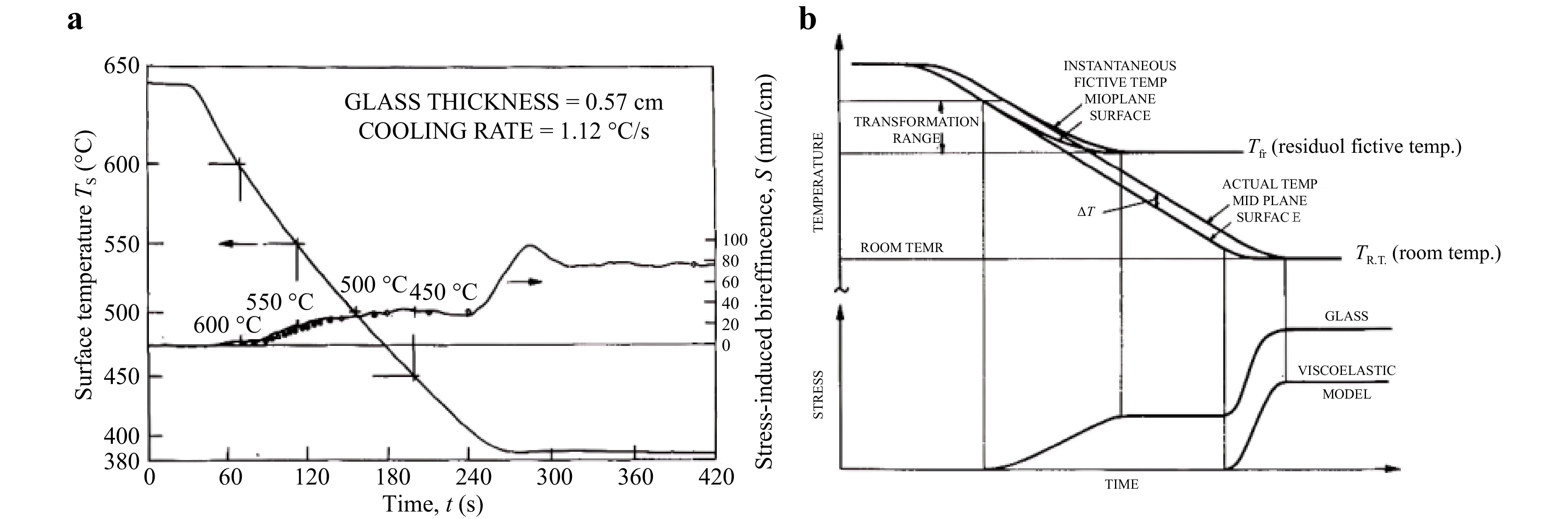
Fig. 16 a Temperature and stress as a function of time during the annealing of sheet glass and b generation of structural and thermoelastic stresses in glass cooled at a constant rate179.
Alternatively, thermal expansion mismatch between glass and molds generates mechanical stresses, particularly for concave lenses. As the mold cools and contracts at a slower rate than the glass lens, the clamping phenomenon creates mechanical stress within the lens, as shown in Fig. 17193. Additionally, thermal expansion mismatch can cause contact separation during cooling, weakening heat transfer and leading to greater temperature variations throughout the lens. Lastly, force applied to hold the glass in place during cooling can introduce mechanical stress, particularly around sharp corners or surface irregularities on molds.
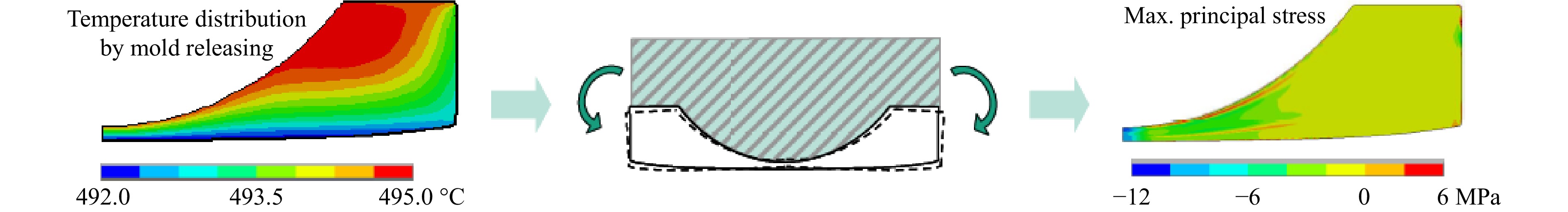
Fig. 17 Temperature gradient during cooling, clamping phenomenon, and residual stress within a concave lens193.
-
FEM simulations have been widely used to predict stress distributions within molded glass lenses. Accurate simulations require reasonable boundary conditions and accurate material characterization, particularly regarding stress relaxation and structural relaxation of viscoelastic glass. FEM simulation results have been validated by photoelastic images using a polariscope91,188,194.
To measure residual stresses within glass, various birefringence-based methods such as stress frozen methods195, integrated photoelasticity196, load incremental approach197, and photoelastic holography198, have been explored. Photoelastic images show an integration of the principal stress differences in the thickness direction. Taking advantage of the weak birefringence of molded glass lenses, residual stresses can be calculated by optical retardation Δ and isoclinic angle φ with a circular polariscope (Fig. 18a, b) using a six-step phase-shifting technique188. The lens was immersed in a tank filled with a refractive index matching liquid to avoid refraction. The relation among optical retardation Δ, isoclinic angle ϕ, and stress tensor components are given as:
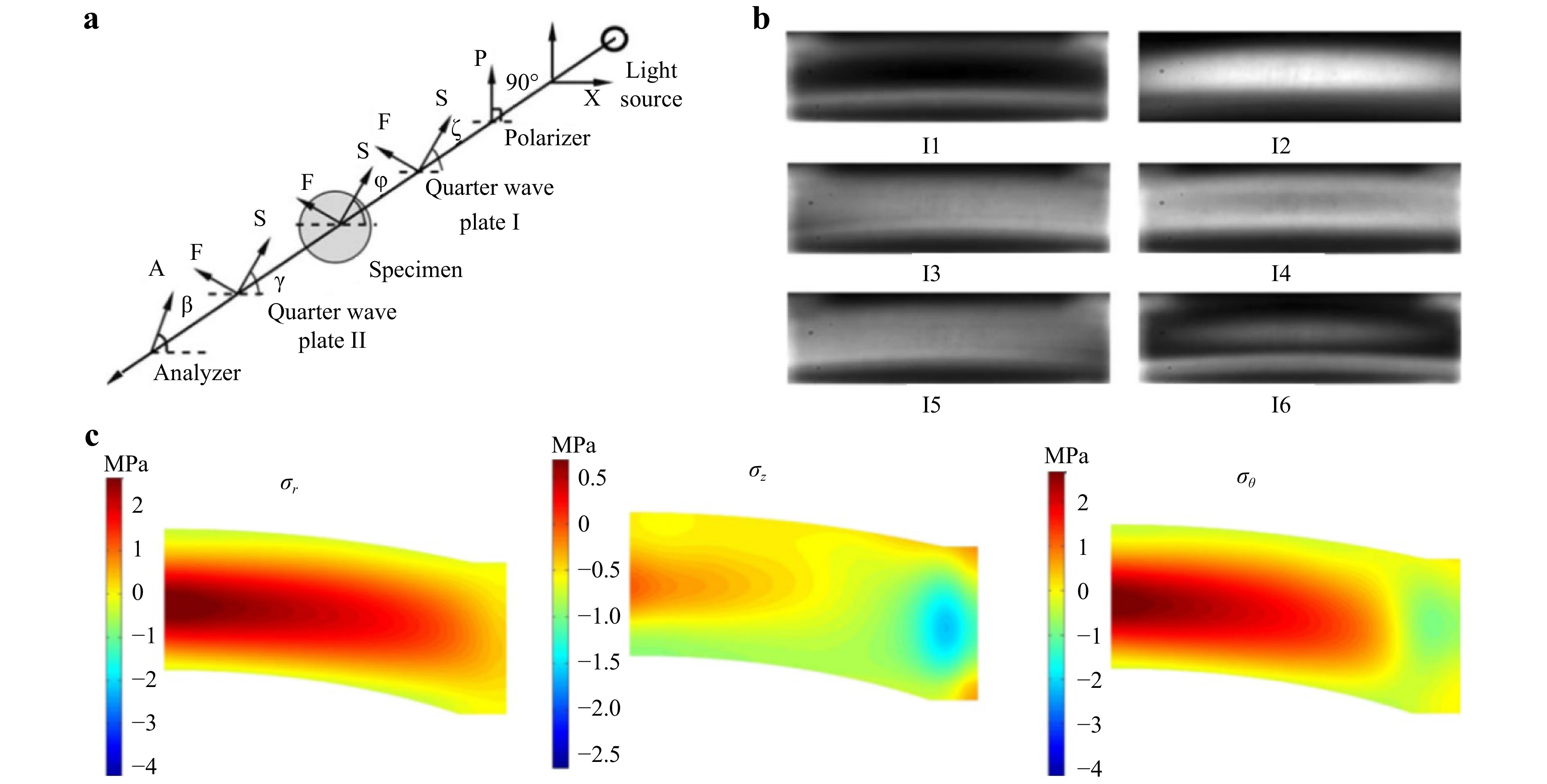
Fig. 18 a Schematic of a circular polariscope for residual stress measurement, b the captured intensity images of the molded lens using six-step phase shifting technique and c the reconstructed residual stress in cylindrical coordinates188.
$$ \Delta {\cos}2\phi ={C}_{0}\int \left({\sigma }_{\textit z}-{\sigma }_{x}\right)dy $$ (19) $$ \Delta {\sin}2\phi =2{C}_{0}\int {\tau }_{x{\textit z}}dy $$ (20) where, σz, τxz and σx are components of the stress tensor in the plane perpendicular to the light ray.
By using three-dimensional spatial equilibrium within the glass lens, axial stress σz and shear stress τrz can be reconstructed by Abel inversion199 or the onion-peeling method200. Then, the circumferential stress σθ and radial stress σr, can be calculated through the equation of equilibrium and generalized sum rule (Fig. 18c). The reconstructed residual stresses were consistent with FEM simulation, but with some degree of error. Errors can be inherited from both experiments used175 and calculation algorithm95.
-
(1) Precise control of the cooling rate, especially around Tg, is critical for minimizing residual stress. To achieve this, a slower nitrogen flow rate is used during the initial cooling phase until the break temperature is reached (Fig. 18a, cited from 95). This slower cooling process promotes a more uniform stress distribution and reduces overall stress. For instance, simulation showed a significant decrease in residual stress, from 14 MPa to less than 2 MPa, when cooling rate was lowered from 10 °C/s to 1 °C/s188. (2) Annealing, a precisely controlled heat treatment after molding, allows glass to relax and significantly reduce residual stress. For example, a 1,600-minute annealing process can decrease the maximum residual stress in a molded aspherical lens, from about 2.5 MPa to less than 0.1 MPa. At same time refractive index variation was also decreased by 4 × 10⁻⁴ 95. Annealing improves production efficiency in batches. (3) Computational modeling plays a crucial role in minimizing residual stresses. By optimizing process parameters, material properties, molds and glass preform geometries, simulations can guide production to achieve lower stress levels.
-
In addition to CTE, index and density variation, other material properties may also experience minute changes during and after molding. One of these properties is Young’s modulus. Accurate knowledge of this value at different temperatures is critical especially for process modeling as Young’s modulus plays an important role in modeling glass especially around molding temperature, or as a supercooled liquid. Measurements using mechanical setup failed to yield accurate readings since supercooled glass relaxes extremely fast as demonstrated by Rekhson and Scherer170,174. One way to rectify this issue is to use an optical method as conducted in a recent work by Jain et al. using Brillouin light-scattering technique177,201 to accurately measure Young’s modulus of two optical glasses at different temperatures (Fig. 19a, b). The measured values drop slightly around glass transition. It is expected that most optical glasses experience similar drop with increased temperature and sometimes it may be easier to just use a small (e.g., ~10%) linear drop in numerical modeling with only minor impact on final lens formation.
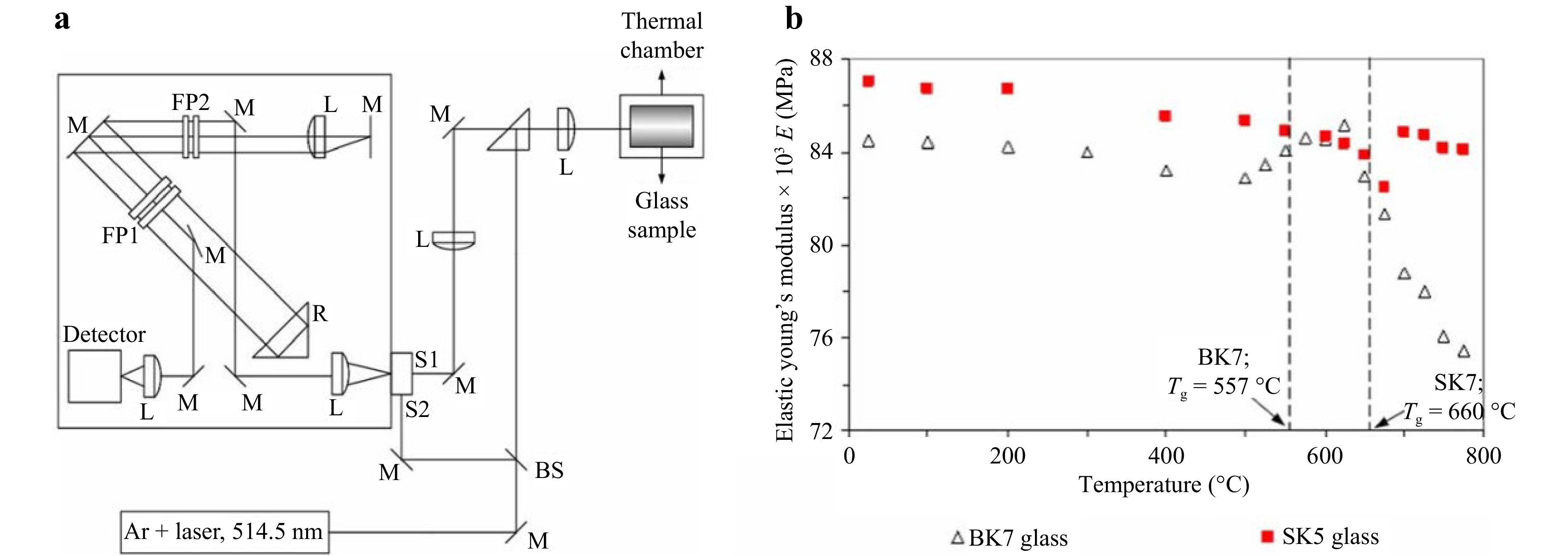
Fig. 19 a Schematic of the experimental Brillouin scattering set-up in backscattering geometry. FP1 and FP2 represent the Fabry-Perot etalons; M, L and S identify various mirrors, lenses and slits, respectively. BS is a beam splitter and R a corner cube201. b Calculated Young’s modulus values from the measured longitudinal and transverse elastic constants at different temperatures for BK7 and SK5 glass using Brillouin light-scattering system shown in a177.
-
In production, molded glass aspherical lenses undergo typical metrology procedures to achieve proper quality. This usually includes mechanical testing that was primarily designed to ensure assembly precision such as lens diameter or aperture, lens center thickness or CT, surface decentration between front and back surface as well as wedge27,114. Different from conventional glass lenses that were machined, as aforementioned compression molded glass lenses experience additional property changes that may require nontraditional measurements. For example, stress evaluation and index variations may also be measured using polariscope and optical methods such as Shack-Hartmann sensor or interferometers176,202,203. Sometimes molded lenses maybe tested in an assembly using MTF (Modulation transfer function) or other optical measures to guarantee final optical performance204,205.
-
Although compression molding is a highly precise and reliable technology with desirable product consistency and simple operations, a major drawback of compression molding is the high thermal mass of mold assembly, including glass lenses themselves. Compression molding is a heat dominant process, both heating and cooling require (sometimes) a significant amount of time for heat to transfer from heat source either directly using infrared heating or by conduction to mold then to glass.
-
To improve the production efficiency of molding technology and shorten process cycle, scholars around the world began to focus on new methods and films for rapid heating in compression molding of viscoelastic materials at elevated temperatures206. A series of investigations have been carried out in the selection of heat sources, such as using joule heating, ultrasonic heating, induction heating, and so on. Joule heating is one of the main attempts. As presented in Fig. 20a, Okulov et al. proposed an advanced Joule heating technique to amorphous Cu47.5Zr47.5Al5 (at.%) metallic glass by controlling the current density and in situ measurement of the resistance of the glass sample207. Li et al. built a platform with a silicon nitride ceramic heater module to conduct rapid heating for optical glass with a maximum temperature of 800 ℃ and a heating rate of 300 ℃/min210. Kimerling et al. developed rapid heating and cooling tools based on resistive heating for polymer microfeatures and narrowed production time to 20 s211. Cheng et al. applied a graphene-polymer composite heater which is benefited from distinguished thermal and electrical properties of graphene to reduce the thermal cycle time to less than 30 s212. However, these graphene coatings adopted in glass/polymer molding are weak because carbon sheets connect with van der Waals force within graphene. Research on localized rapid heating by a newly-developed durable and robust graphene like coating will be introduced in section 5.3.
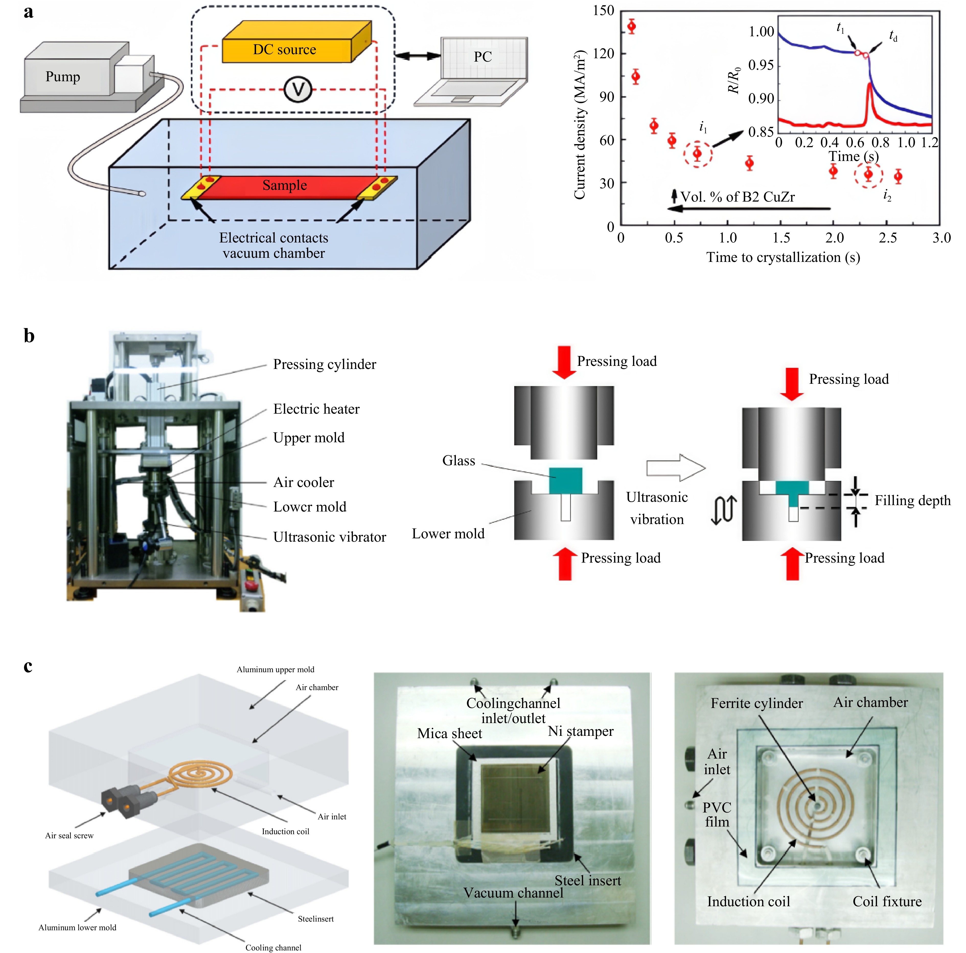
Fig. 20 a Joule heating of Cu47.5Zr47.5Al5 glassy ribbons and current density plotted against time until devitrification onset207, b Self-developed ultrasonic vibration assisted pressing machine208, c Novel inductive hot embossing assembly: a hot embossing mold with a single-layer spiral inductive coil209.
Ultrasonic heating is another attractive rapid heating strategy used in hot embossing. Chang et al. proposed an ultrasonic assisted hot embossing process for rapid fabrication of microlens arrays with satisfactory geometrical and optical properties and a total cycle time of less than 10 s213. Liu et al. attempted to use ultrasonic vibration as a heat generator for hot embossing instead of conventional electric heating214. Xie et al. employed an FEM software Abaqus to study the mechanism of glass microgroove forming by ultrasonic vibration assisted hot pressing215 and the same group then continued their efforts on the improvement of glass formability in micro cavities with high aspect ratio structures based on ultrasonic vibration molding216 by a self-established molding machine in Fig. 20b. In Roylance et al.’s model, they applied ultrasonic vibration to produce heat to cure fiber-reinforced thermoset polymer composites217. Nguyen et al. established an FEM model for pressing stage of an ultrasonic vibration assisted glass molding process to demonstrate that heat can be generated in ultrasonic vibration process218.
Induction heating is also one of the popular rapid heating approaches and many scholars contribute in this area. Instead of volumetrically heating the entire mold in traditional approaches, Nian et al. rapidly heated the stamper surface by using induction coils to reduce cycle time to approximately 45 s209, the setup of which has been described in Fig. 20c. Fu et al. developed an induction heating apparatus for thermal imprinting with nickel mold where heat is generated by eddy current and magnetic hysteresis losses of the ferromagnetic nickel mold at high speed219. Saotome et al. heated Pt48.75Pd9.75Cu19.5P22 metallic glass at a rate of up to 100 K/s by induction heating220. Yun et al. developed a roll-to-roll hot embossing system with induction heater for micro fabrication221.
In addition, there are also other unique rapid heating methods. For instance, Kurita et al. combined laser and embossing to initiate a rapid process, whose heating time is less than conventional hot embossing because only a particular area of mold is heated222. Chang et al. utilized fluids as heating and pressing media including steam, gas, and oil, resulting in heating a 0.2 mm thick PVC substrate from 25 to 130 ℃ in 30 s, 25 s and 3.5 min through using steam heating, FIR heating, and oil heating, respectively, which are all faster than conventional heating223.
These methods all have certain advantages and limitations. For example, ultrasonic heating is featured by its high material filling ratio in micro structured cavities while cannot provide sufficient heat for large workpieces and molds; Induction heating is easy to realize higher heating rates yet difficult to achieve uniform heating of molds with inconsistent wall thickness or complex shapes; Temperature of fluid assisted heating is difficult to reach Tg point of most glass materials, generally more than 300 ℃.
-
Among rapid heating methods and materials, carbon bonded graphene coating stands out as an efficient thermal film for glass molding with less power usage and high heating efficiency. Compared with existing molding technology, it can also reduce residual stresses by orders of magnitude, improve molding efficiency and subsequent optical performance of the molded lenses.
The thin layer of three-dimensional carbide-bonded graphene coating with extraordinary mechanical properties was first prepared by L. James Lee et al.86. The formation mechanism of these carbide-bonded graphene networks is presented in Fig. 21a. Unlike atom-thick graphene building blocks with limited dimensions having weak van der Waals interactions with substates, this novel three-dimensional crosslinked graphene networks by covalent bonds with few atoms such as -Si-, -SiO-, -OSiO-, -SiC-, or -CSiC- present excellent mechanical performance in constant heating/cooling cycles under pressures. He et al. then found this graphene like coating enables silicon based materials as mold to create delicate microstructures with high-precision dimensions and perfect consistency which had not been accomplished previously due to severe inhesion between silicate glass and silicon molds127. To identify any potential issues coating curved surfaces over large areas, a 63 mm diameter convex surface of a Si lens with sagittal depth of ~9.6 mm was coated with graphene networks, as shown in Fig. 21b. We can clearly see from the figure that large-area curved surface can also be coated with dense uniform graphene like coating, providing a path for aspherical lens molding by graphene networks.
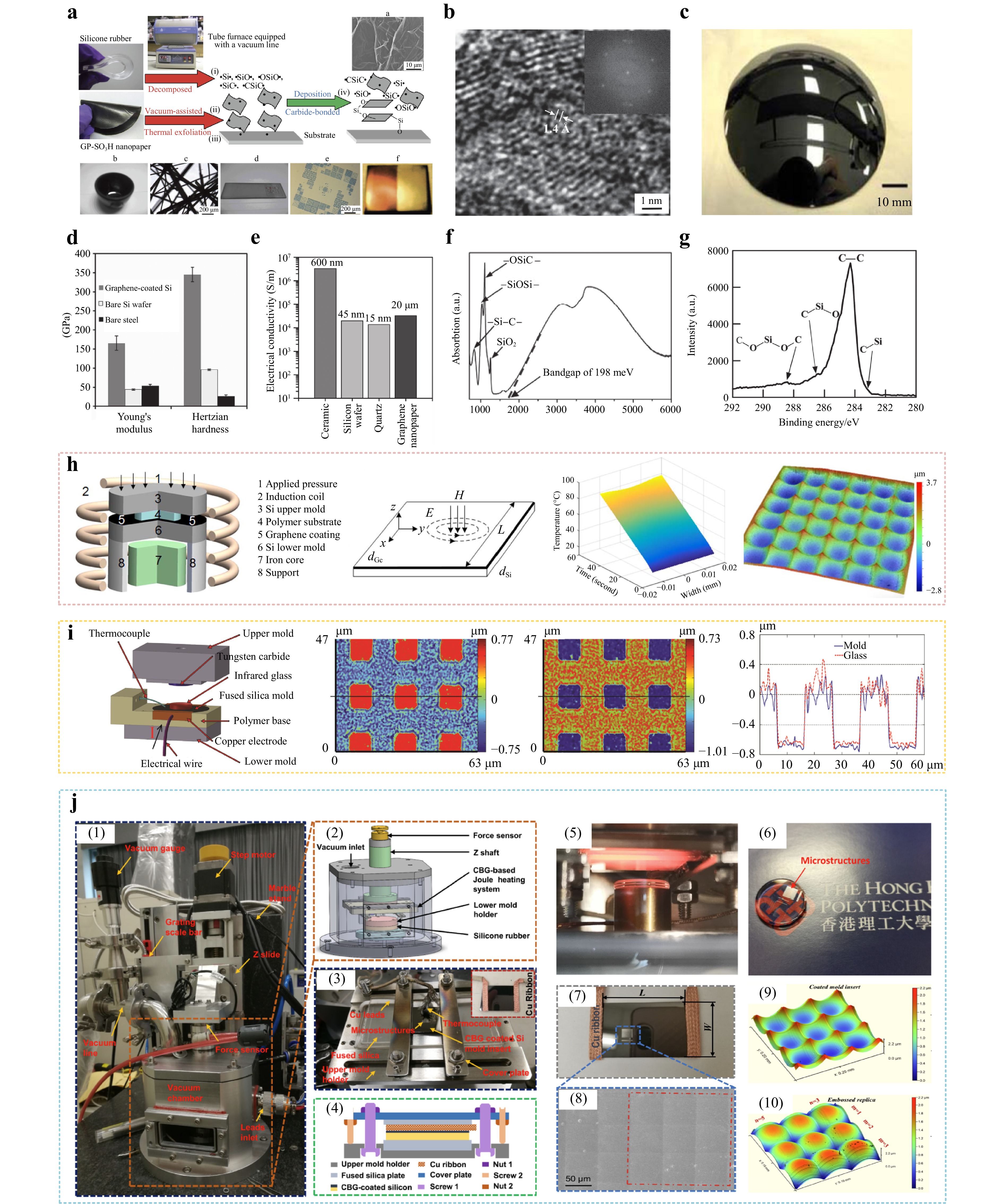
Fig. 21 a Mechanism for building up carbide-bonded graphene networks on metallic or non-metallic surfaces in a tube furnace equipped with a vacuum line, b Graphene fundamentals, c A 63 mm diameter Silicon lens coated with carbon bonded graphene coating, d Young’s modulus and Hertzian hardness of carbide-bonded graphene networks on silicon wafer (grey color), bare silicon wafer (white color) and bare O1 tool steel (black color), e Electrical conductivities of carbide-bonded graphene networks on ceramic (~600 nm), silicon wafer (~45 nm) and quartz (~15 nm), as well as GP-SO3H nanopaper (20 μm), f FTIR absorption spectrum of ~45 nm thick carbide-bonded graphene networks on silicon wafer, where the x-intercept of absorption spectra of the lowest band edge determines the bandgap of about 0.198 eV, g C(1s) XPS spectrum for carbide-bonded graphene networks on ceramic. a-g are all from86. h Localized rapid heating process by induction for polymeric lenses224, i Localized rapid heating process by electrical joule heating for infrared glass lenses225, j Localized rapid heating process by electrical joule heating for glass lenses140.
Apart from high hardness and stability, the integrity and lifespan of the carbon bonded graphene coating are also some of the most important properties in precision molding. A well prepared graphene coated mold (Fig. 21c) can repeatedly complete the precision molding of polymer and glass aspherical lens and microlens arrays. However, when the number of moldings reaches a certain value, the graphene coating will peel off slightly. At this time, the mold has reached the end of its life and cannot be used anymore. The properties of the graphene like coating are shown in Fig. 21d-g.
Another advantage of the graphene like coating is it possesses high electrical conductivity of 1.98 × 10⁴ S/m and low surface resistivity of 20.4 Ω. Thus, this coating can quickly generate and release/transfer heat, softening optical material and replicating the mold profiles onto the surface of optical materials. Xie et al. soon came up with a simple rapid hot embossing system utilizing the carbon bonded graphene coating on micro-structured silicon molds to conduct rapid heating and cooling of the polymer139. By adopting this new method, heating rates of 5–10 °C/s was achieved by employing a 50V DC voltage. When voltage of the power supply is increased, higher heating rates can also be obtained. Since temperatures of the mold and the polymer can rapidly ramp up to Tg within seconds, the rest embossing equipment still remains at low temperature so the mold surface can be cooled down at fast speed after embossing. To investigate the heat transfer in the new rapid heating and optical property of molded polymer, Liu et al. carried out finite element method (FEM) simulation to interpret temperature variations among graphene like coating and heat transfer between coating and polymethylmethacrylate (PMMA)226. They also verified that much improved optical properties such as less wavefront variation and refractive index change can be obtained in molded polymer optics by this rapid heating because most part of the polymer does not experience heating and cooling due to extremely short cycle time. Zhang et al. proposed a novel method of a localized rapid heating process based on induction heating of the graphene coating (~45 nm), and a high heating rate of 10−20 °C/s can then be achieved for an overall thermal cycle of about 3 min or shorter (Fig. 21h)224.
As polymeric microlens array had been successfully produced, optical materials such as chalcogenide glasses with higher Tg were then tested by Li et al.225. They adopted the thin graphene layer to heat only the surface of the glass so that most part of the infrared glass maintained solid status to provide better support during pressing, thereby the features being replicated by straight edges has higher quality than the slanted surface using conventional heating, as shown in Fig. 21i. After that, scholars from The Hong Kong Polytechnic University have extended the localized rapid heating method for graphene coatings to optical materials such as silicate glass P-SK57 based on the Joule heating (Fig. 21j). A home built micro hot embossing device with precise temperature control was established and glass microlens arrays were hot embossed by using the device227,140.
-
Several options exist to increase production in glass molding. Logically one of the paths to increasing production is similar to semiconductor process—increasing the number of devices on a single wafer. Most university cleanrooms are equipped with four- or five-inch wafer aligners, but industrial standard today has reached 12 inches with 14 inch wafers becoming the next standard. Following this thought and considering the demand for micro and meso scale optics, wafer level glass molding for optical fabrication has been explored for consumer applications. With the ongoing miniaturization as well as the continuously growing quantities in glass optics manufacturing especially for consumer electronics and smart terminals, precision molding of such optics at wafer scale is becoming an alternative solution, which can keep the production cost and handling efforts of these optics as low as possible43,228–230. For wafer level glass molding process, a polished glass wafer is heated and pressed into the desired shape using ceramic or metal molding tools. Similar to semiconductor industry in highly efficient manufacturing millions of packaged chips, glass wafers after molding can be stacked, bonded and subsequently diced into hundreds or thousands of single optical modules, with optics size from micrometers to millimeters231, as shown in Fig. 22a.
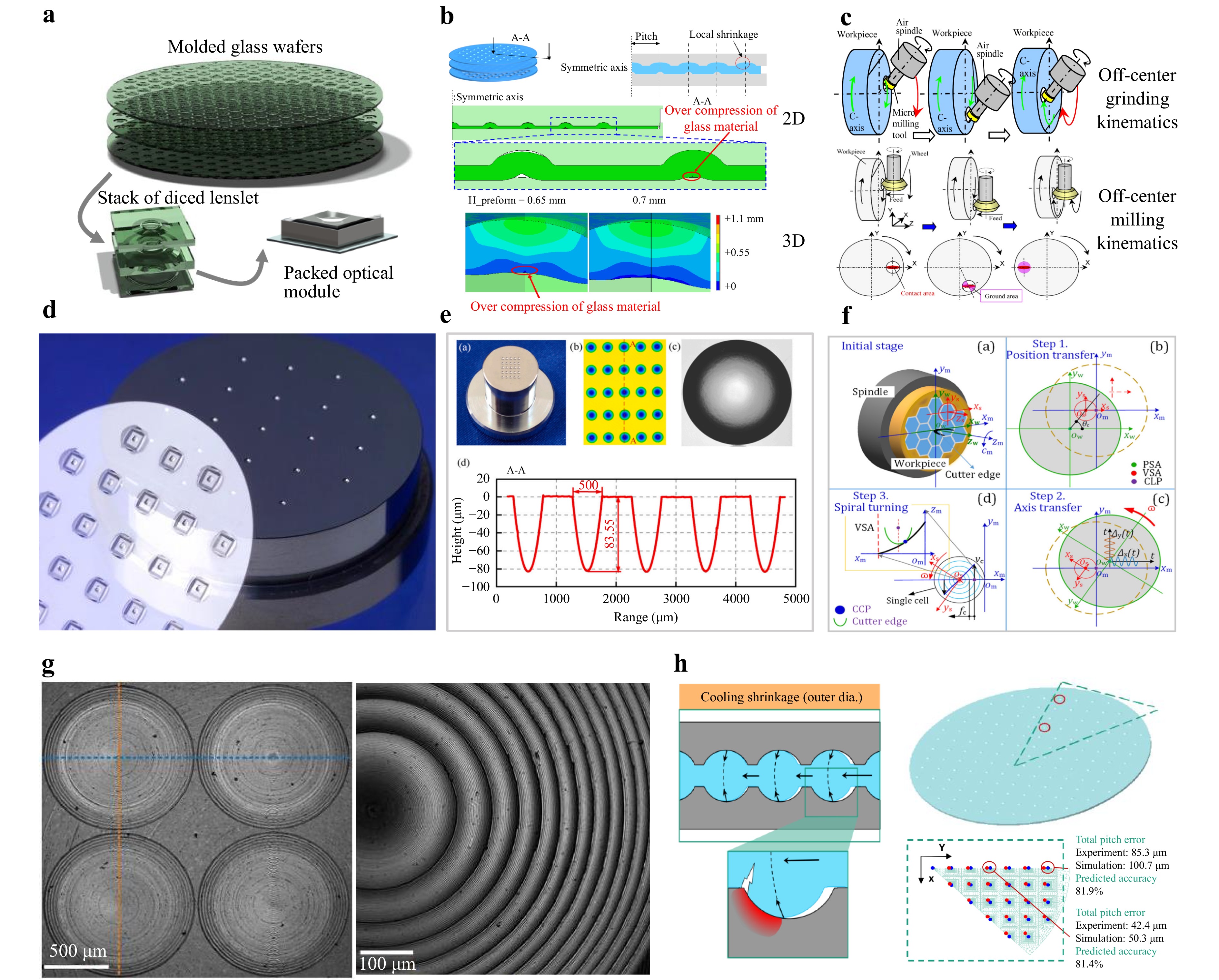
Fig. 22 a Wafer level glass molding process flow231. b Glass flow and shrinkage during wafer level molding232,233. c Ultraprecision grinding processes developed for tungsten carbide glass mold inserts229,230. d High speed diamond milling for micro-lens array fabrication236. e Local spiral diamond milling for high aspect-ratio nickel phosphorous lens array mold fabrication237. f Virtual spindle-based tool servo diamond turning method designed to machine discontinuously structured microlens array molds238. g Fresnel lens array mold fabrication method utilizing virtual spindle tool servo process239 and h CTE mismatch between mold and glass material could potentially result in significant defects in molded lens arrays43.
Another wafer level optics manufacturing method can be called plastic wafer level optics (WLO) technology through nanoimprint lithography (NIL), an established process in which a wide variety of micro-optics can be produced on wafers up to 300 mm in size232,240, where lens patterns are transferred into optical polymer materials by soft UV imprint lithography at room temperature using stamps replicated from wafer-size master, and has proven to be an effective tool for mass production232,233,240. However, for WLG production, technologies are significantly more complex, since glass needs a much higher temperature to reach proper thermal rheological properties for forming. Due to high forming temperature, chemical interaction between the forming tool and glass becomes vigorous during molding and tool wears out quickly241. Similar to common precision glass molding, the key molding processes of WLG also include typical process steps, such as heating, forming, annealing and demolding, but the process conditions for each step is more stringent and may even be different from common precision glass molding.
The first step in WLG process workflow is usually wafer mold design, where mold surface contour is derived from the optical design. However, cavity design is not just the negative shape of the optics, because shrinkage and glass flow behavior must be considered as shown in Fig. 22b. An efficient way to optimize mold design and study glass filling behavior is to adopt finite element simulation, where glass viscoelastic rheology, structure relaxation, thermal expansion, contacting behavior as well as other material properties are considered229. A systematic methodology of WLG molding simulation is presented by Klocke et al.230, in which the work is subdivided into 2D and subsequent 3D simulations. Following such a procedure, a wide range of mold designs can be quickly evaluated through 2D simulation, such as arrangement of upper and lower molds, rationality of mold structure design, prevention of undesired glass material flow, such that only a few iterations of the 3D wafer simulations for those error compensations mentioned above are required, which could significantly increase the entire process simulation efficiency. Besides, in their study, a molding process of a 100 mm diameter glass wafer is simulated, and the pitch errors are compared with the experimental results with predicted accuracy above 80%. However, research on WLG simulation is still in its early stage, more work is needed in this topic for future study.
Compared with numerous fabrication techniques, such as physical and chemical methods, precision machining is still considered the most suitable technology for WLG mold manufacturing, since WLG mold material is usually very hard and the surface contours of finished molds need to have well-defined intricate shapes or homogeneous surface integrity239,242,243. Two typical machining methods, precision grinding/milling and single-point diamond turning, are widely adopted in lens array type mold fabrication88,243,244. To manufacture hard metal alloy molds for WLG replication, the center-oriented kinematics grinding method such as cross axis or parallel grinding229 are no longer appliable, while the off-center kinematics grinding is a reasonable solution. Yamamoto et al.234 developed an ultraprecision grinding system with simultaneous 4-axes motion as shown in top part of Fig. 22c, and successfully fabricated a tungsten carbide lens array (25 lenses) molding die with surface figure accuracy about 0.1 μm in PV and surface roughness about 7 nm (Rz). Suzuki et.al studied off-center milling of WC array molds using a 4-axis ultraprecision machine235, as shown in lower part of Fig. 22c. And in their study, micro milling tools made of polycrystalline diamond (PCD) were developed, and the tool wear decreased to 1/10 compared with the conventional diamond wheel, and WC array mold surface roughness of 10 nm Rz was obtained. Gao et al. studied micro ball end-milling fabrication of a microlens array mold made of AISI H13 tool steel, and their experimental results showed that a three-dimensional (3D) offset spiral strategy could achieve a higher machining quality in comparison with other strategies assessed in this study242. Li et al. studied the high-speed diamond micro-milling of 6061 aluminum alloy microlens array mold of 25 mm in diameter, 40,000 rev/min milling rotational speed, 100 mm/min feedrate, 20 μm roughing depth as well as 3 μm finishing depth of cut were used as the process parameters, and a lens array mold with form error less than 200 nm, surface roughness ~35 nm was obtained as shown in Fig. 22d236. Zhou et al. studied a local spiral diamond milling method to manufacture lens array mold with high aspect-ratio, nickel-phosphorous (Ni-P) plated lens array mold were generated with profile accuracy (PV) less than 1 μm and surface roughness (Ra) less than 14 nm, as in Fig. 22e237.
Compared to off-center grinding or milling method, single point diamond turning is more capable and flexible in manufacturing lens array mold, usually in the form of slow and fast tool servo (STS and FTS) diamond turning technologies. Diamond turning process with slow tool servo is much easier to setup, but sometimes to increase bandwidth of tool stroke, fast tool servo has been developed to manufacture optical surfaces with fast changing structures243,245–247. However, for large scale lens array mold fabrication, such as WLG molds, it is still challenging to use FTS due to limitations of this technique246 while STS is more applicable for this type of mold manufacturing. Recently, Zhu et al.246 introduced a virtual spindle-based tool servo diamond turning method for the generation of discontinuously structured microlens array mold, and the basic machining principle is shown in Fig. 22f238. By applying the virtual spindle-based tool servo strategy, Zhang et al. achieved flexible fabrication of a Fresnel lens array mold, as shown in Fig. 22g239. Since the virtual spindle tool servo enables shift of the virtual spindle to coincide with the axis of each lenslet, applying the method in fabrication of the lens array mold especially at large scale, such as a WLG mold, would be much more promising.
As mentioned before, the basic principle of the wafer level glass molding processes is similar to that of already established precision molding. During heating, glass wafer preform is heated together with the mold assembly. High temperature homogeneity inside glass preform is extremely important. Uneven temperature distribution will cause forming quality differences for lenslets located in different areas of the wafer or even molding failure. For wafer level molding, single station glass commercial molding machines, such as Moore Nanotech GMP 170GMP, Toshiba GMP-311V and GMP-315V, are usually used, and these single station molding machines are heated using infrared lamps as mentioned earlier. However, it is challenging to achieve high homogeneous temperature distribution using only infrared heating mode. By comparison, hybrid heating method by combining infrared or microwave heating with electrical heating24 could be a balanced solution for better heating performance248. During cooling in precision glass molding, molded glass deviates from the mold surface due to thermal expansion coefficient (CTE) difference between glass and mold materials, which would be beneficial for demolding of molded glass optics. For cooling in WLG molding, however, the CTE difference will cause deformation or even damage of the lenslets located in outer areas of the mold glass wafer, because lenslet mold surface could crack the lenslet surface as shown in Fig. 22h43. As studied by Klocke et al.230, the pitch error could reach over 85 μm due to CTE mismatch. Therefore, during WLG mold design, CTE matching between glass and mold material should be carefully managed.
Table 4 summarizes key performance indicators including geometric accuracy, surface finish, cycle time, and cost for three representative methods: conventional compression molding, rapid surface heating molding, and wafer-level glass molding (WLG).
Method Geometric accuracy (PV/μm) Surface finish (Ra/nm) Typical cycle (min) Estimated unit cost Conventional molding ~ 1−3 ~ 5−10 30−50 Medium-high Rapid heating molding ~ 1−2 ~ 3−7 5−10 Medium Wafer-level glass molding ~ 0.5−1.5 ~ 2−5 < 3 (batch) Low Table 4. Key performance indicators of three representative methods
-
It is generally accepted that most classical mechanical processes are deterministic, i.e., cause and effect. Within the physical limits of the process, results can be precisely predicted if causes are known a priori. This cause-and-effect is the foundation for process optimization in industry249. In glass molding, as discussed before, due to thermal shrinkage and structural relaxation, glass lenses will experience shape and material property changes that usually far exceed the tolerance requirements for imaging optics (Table 1). This is handled using multiple iterations during manufacturing, usually through a combination of simulation and small batch production runs. We loosely use the phrase optimization in this review to refer to all efforts implemented in production to improve cycle time and lens quality and should not be interpreted as precisely defined rigorous mathematical operations.
-
The overarching goal of glass molding process optimization has three major components130, i.e., a representative merit function, robust algorithms, and criteria for evaluation. Merit functions will need to include major process parameters in some mathematical formulation. Typical algorithms include simplex131,132, genetic algorithms129 and other options250. To model lens deformation and property changes that cannot be measured in real time, numerical modeling utilizing finite element analysis is becoming the primary tool110,184. Loosely defined and briefly mentioned earlier, from optical design, to mold design and fabrication eventually to molding, one full cycle is an iteration of molding process and this optimization may be repeated until the most favorable process condition is reached. During each iteration, many process variables are numerically modeled since material properties undergo significant changes as discussed earlier and these changes are difficult or cannot be measured in real time precisely. An overall process flow will look like the flowchart below (Fig. 23a, b) and this process will be repeated until a satisfactory lens is obtained. It is evident from this flowchart that mold surface rarely starts with original optical design due to thermal shrinkage of the lens and mold. Ideally this iteration cycle is completed before the lens mold is tooled out and it may be continued indefinitely during production to maintain quality of molded lenses as production conditions vary from time to time, sometimes significantly.
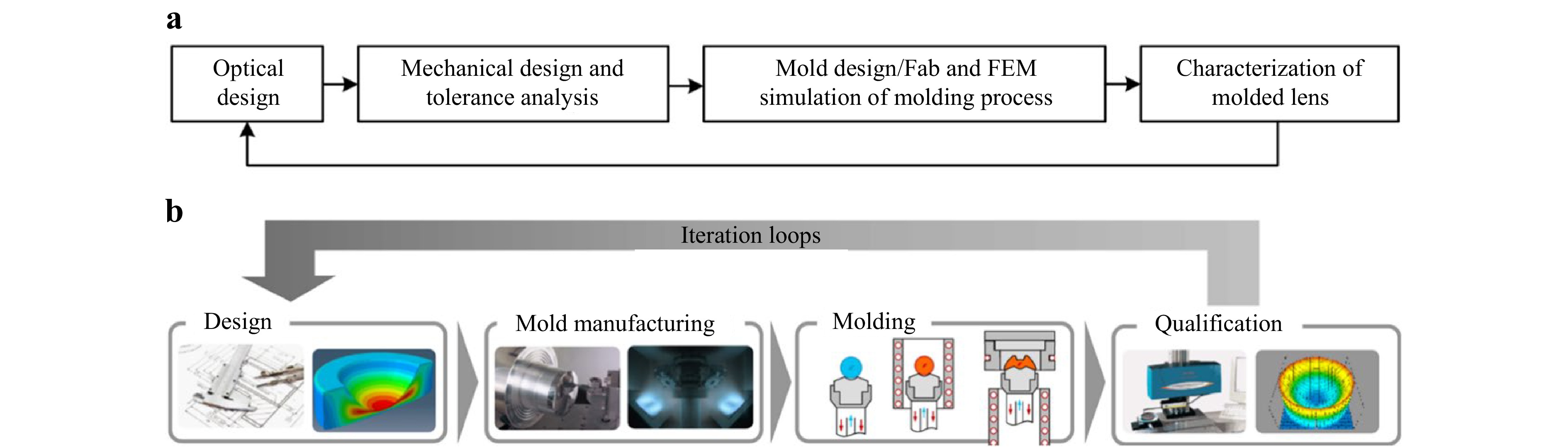
Fig. 23 a Flowchart of process development and b process development and optimization depicted more graphically in reference251, an non iso-thermal molding process for a non-imaging glass optical lens. These lenses have lower tolerances than imaging optics, but molding procedures and process optimization are more or less the same.
Unlike other high volume forming process such as injection molding where high number of replicas can be easily reproduced thus providing ample results for optimization252,253, glass molding is inherently complicated from the start. Tooling and optical materials are somewhat expensive to prepare due to the high cost of materials and fabrication. This makes it difficult to optimize solely using an experimental approach. The current scheme of process optimization relies heavily on numerical simulation as direct full control of process conditions is hard to achieve in practice. Key process parameters such as temperature and pressure inside glass are difficult if not entirely possible to measure in real time. Thermocouples embedded in mold inserts cannot even measure the mold surface temperature due to constraint of the sensor location. Thermal resistance at glass-mold interface means the temperature control will inherently experience delays and temperature inside glass can only be inversely calculated. Mathematically these are characteristics of an ill-conditioned problem and fundamentally a very undesirable situation for real time process control.
-
Compression molding of glass lenses is subject to many influences, in another word, glass molding process has high uncertainties. Furthermore, manufacturing processes are often considered trade secrets by private companies such that public does not have quick access to even the basic setup (glass material compositions, mold design and materials, molding temperature history, pressing force, heating and cooling rates etc.). Consequently, optimizing the glass molding process is challenging, necessitating the use of advanced statistical methods and optimization algorithms.
To conduct a process optimization, first a merit function represents a performance measure that is important to lens quality needs to be defined. For example, geometric measurements of a molded lens, wedge, decentration, center thickness or physical properties such as index (change) and residual stresses need to be constructed. Glass molding in manufacturing include everything from optical design to final assembly inspection so one such merit function f(x) can be defined as the sum of design error, tool path generation error for mold fabrication and molding error (dimension of m), roughly can be written as (modified from254, page 11):
$$ \phi \left({\boldsymbol{x}}\right)={\sum} _{j=1}^{m}{w}_{j}{\left[\overline{{f}_{j}}\left({\boldsymbol{x}}\right)-{\overline{f}}_{tar,j}\right]}^{2} $$ (21) where x = (x1, x2, …, xN) describes a point in the N-dimensional variable space, $ \overline{{f}_{j}}\left(\boldsymbol{x}\right) $ are the operands with target values $ {\overline{f}}_{tar,j} $ and positive weighting factors wj. ϕ(x) is then a single number giving the difference between the various operands and their target values. Examples of operands can be ray displacements (e.g. transverse ray aberrations of individual rays), optics parameters to be held within certain limits, machining tool radius, mold cavity dimensional (change), molding temperature, molding pressure, and other process variables maybe critical to final results. The goal of the optimization process is to find the minimum of the merit function ϕ(x) in the multi-dimensional variable space (x), For example, typical least mean square optimization will seek to find a set of xj which satisfy the condition:
$$ \frac{\partial \phi }{\partial {x}_{i}}=0 (i=1, 2, \dots N) $$ (22) Prior to full scale optimization, design of experiments (DOEs) within the boundary of molding process are common practice in high volume molding processes such as injection molding255. This approach was tested in compression molding of BK 7 and L-BAL57 glass optics. In this work, process variables such as temperature, pressure and were assigned a range of possible values using the popular Taguchi method. Molded lenses under different conditions can be evaluated, in this research an important optical parameter, i.e., center thickness was chosen as the performance measure of the experiments. In total, 18 separate experiments were conducted (as opposed to a full factorial analysis of 1,458 experiments). The experiments were performed using an industrial molding press from Dyna Technologies Inc. (now defunct). After the experiments, it was determined that glass type does not impact center thickness significantly thus was removed from the parameter list. In addition, due to significant importance of viscosity to the molding process, it was decided a constant value needs to be held during the experiments. After this adjustment five parameters remained, i.e., heating rate, soaking time, molding force, cooling rate and forming force. A revised DOE table was derived as listed in Table 4. Naturally, experiments confirmed that cooling rate remains the most significant factor in molded lens thickness. Follow this idea, other approaches such as neural network can also be adopted for process improvement256. Due to the ill-conditioned nature of glass molding, artificial intelligent methods such as machine learning maybe more appropriate257.
In another effort, a hybrid optimization approach was developed for non-isothermal glass molding, by addressing an optimal configuration for two separate stages (Fig. 24a258,251). To achieve optimal quality outcomes, this approach utilized a neural network-based optimization algorithm for selecting the optimal glass preform and molding process parameters, including mold temperature, glass temperature, molding velocity, and applied force. Zhang and his colleagues applied typical optimization algorithms to the glass molding process, as illustrated in Fig. 24b, c. In a series related publications56,190,259, they applied algorithms such as the simplex method into molding process optimization. For example, Liu et al. implemented a numerical optimization platform for glass molding that combines a simplex algorithm and finite element simulation259. They reported that this platform effectively reduces residual stress through cooling process optimization and minimizes the profile deviation using mold shape compensation (Fig. 24d-i).
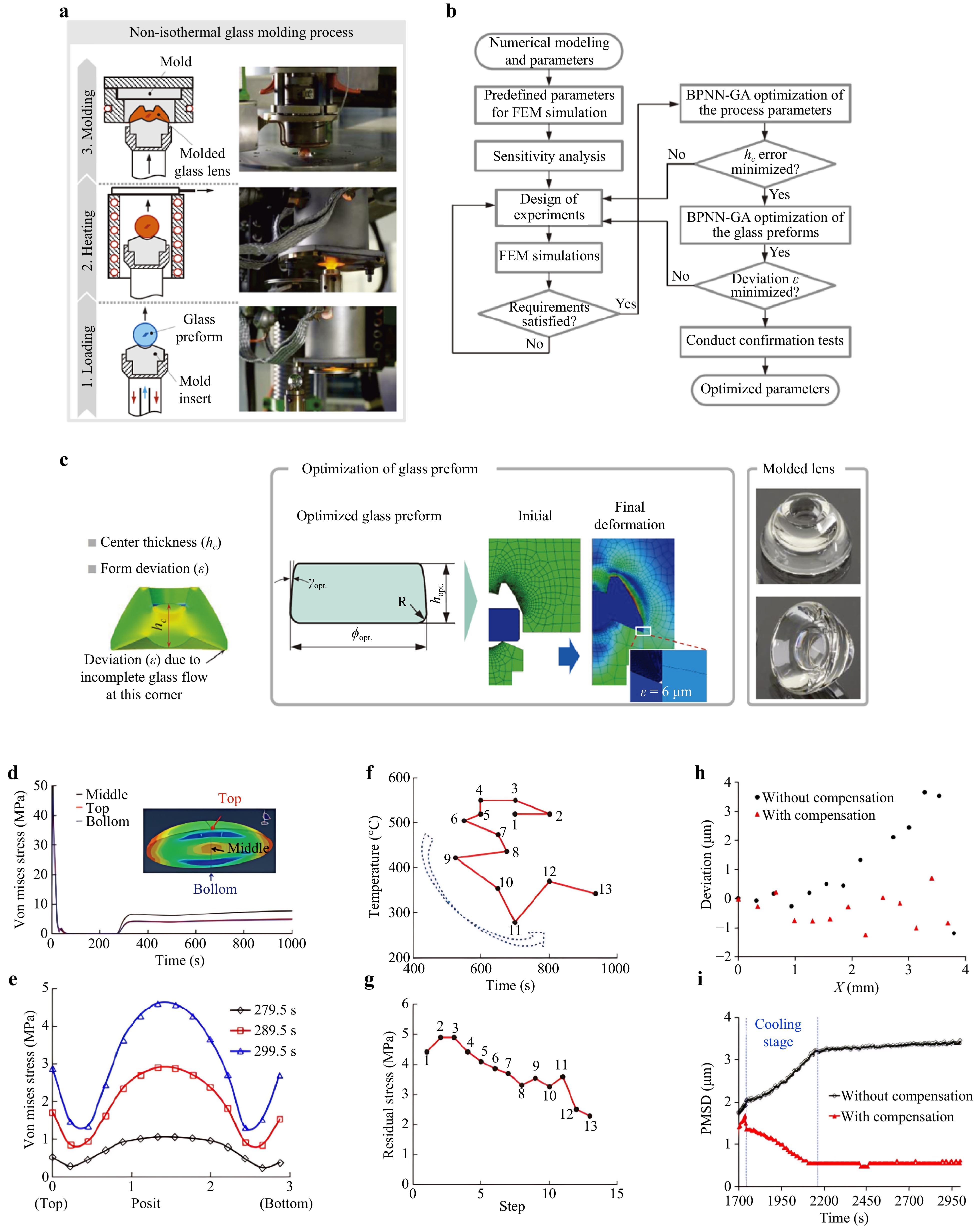
Fig. 24 Design of experiment and machine learning in process optimization. Profile deviation of molded lens with and without die compensation and changes of surface profile after applying simplex optimization during molding. Numerical optimization using numerical analysis such as Simplex for process optimization. a-c is from Refs. 251,258, d-g are from Ref. 56, h and i are from Ref. 259.
-
After glass molding is optimized for optimal process conditions, molded lenses may still experience quality issues, e.g., lens profile deviation may still fail inspection due to thermal gradients experienced during molding. As a result, glass lenses may have substantially different shape and thickness from the mold pair used. Since glass molding experiences large thermal gradients both spatially and temporally, this characteristic changes during molding dictate the final lens geometry and also the lens property therefore compensation for lens properties including geometry deviation and optical property changes such as refractive index variations can be a complicate undertaking due to limited control variables with mold profile being the primary choice. Specifically, to compensate for thermal shrinkage in both lens and molds, mold surfaces need to be reformulated to create a pre-determined deviation. In industry, preamble steps are taken to shift the mold surface in an attempt to allow the lens material return to the desired size and geometry when lenses are cooled to ambient temperature such the lens performances will match the original optical design. Using first order approximation as a start, aspherical parameters for the new mold surface expressed in Eq. 1 can be identified. Since the aspherical polynomial is not a linear function of radial distance x, it is difficult to directly perform best fit calculation. One practical approach is to vary vortex radius R and conic constant k then calculate aspherical coefficients As from either simulated information or experimental measurements. Once a new aspherical equation that provides the best surface for molding is identified, it will need to be entered into an FEM program to calculate exact lens final shape after molding. In this review, we focus primarily on numerical modeling of glass lens itself. Readers can find more information regarding mold fabrication in the refences cited earlier and the information therein.
Due to changes of optical properties in glass after molding (e.g., index, residual stresses), this compensation also needs to take the change of optical properties into consideration as aforementioned. A quick solution in optical design is to simply add a small value (index drop) in material selection. However, this approach ignores the complicated index variation across the entire lens body especially for lenses with large volume where index variations tend to be high. Index variations across lens bodies become especially significant for lenses of complicated geometry or geometries with high degree of thickness variation. Straight addition of a fixed index change does not account for the lens geometry complexity, real solution requires modifications to the existing design software, notably Zemax and Code V to take index distribution into consideration, effectively treating the molded lenses as three-dimensional GRIN lenses. This remains an unfinished task since molded glass lenses have not been implemented in optical design in large numbers. Thermal shrinkage of glass lens and mold can be offset by a fixed amount, but mold surface normally requires a new set of conical constant and aspherical coefficients since the aspherical equation is widely accepted in optical industry. Curve fitting such as cubic spline can be simpler but geometry eventually needs to be converted into a formula that optical design software can recognize and utilize.
As a case study, it was proposed that a numerical simulation assisted profile compensation scheme be used for molding high-precision aspherical glass lens (Fig. 25a, b)109,260. The process begins with finite element simulation to precisely predict the profile deviation, or shrinkage error, that will occur in the molded lens. Based on this predicted deviation, mold’s profile curve is then adjusted to compensate and produce a lens with the desired profile. Experimental results confirmed that lenses molded using the compensated molds exhibited significantly better agreement with the intended design. This mold profile compensation scheme not only significantly improved the form accuracy of molded lens, but also ensured an efficient mold manufacturing with lower production cost and shortest cyle time.
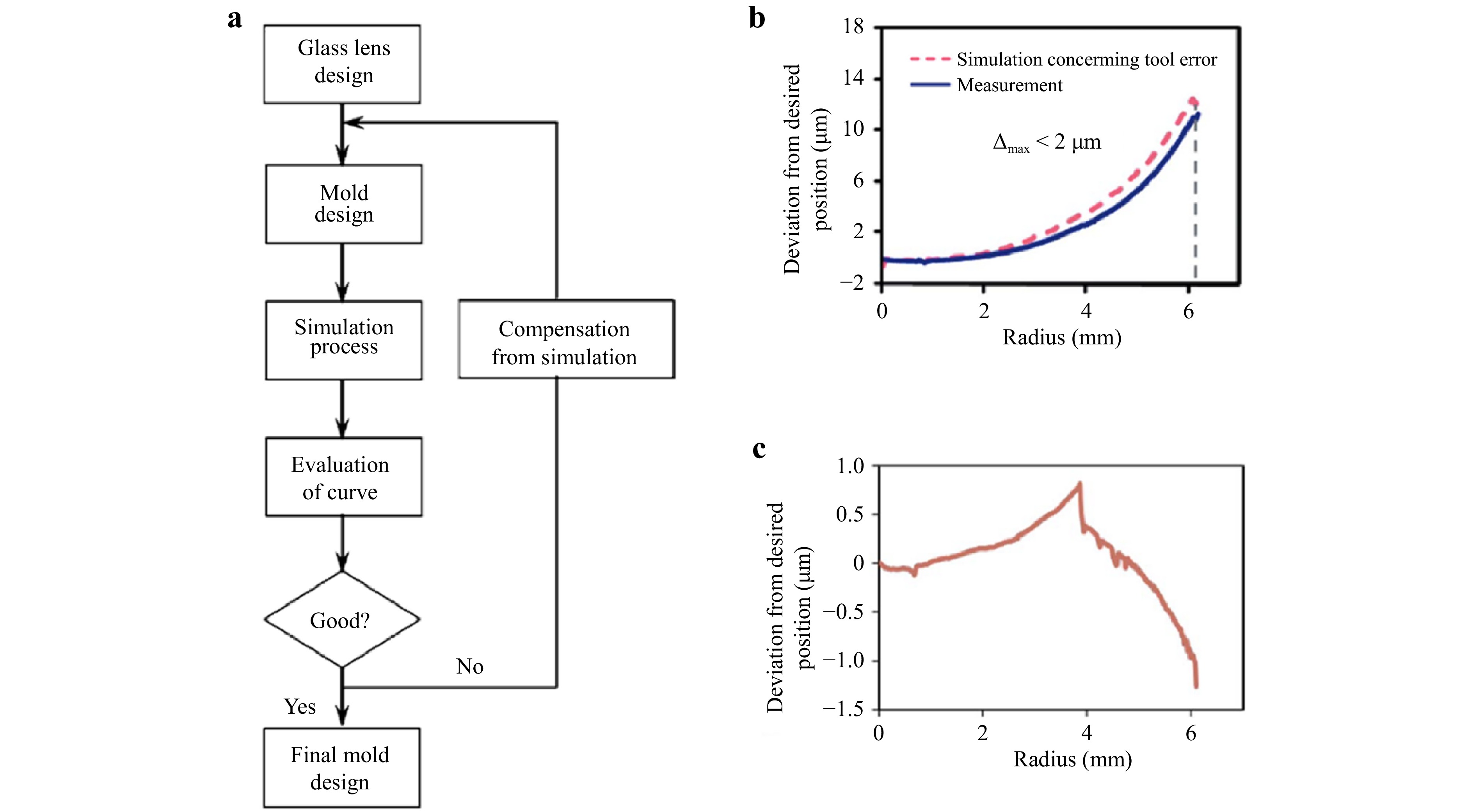
Fig. 25 a Flowchart of the numerical simulation assisted profile compensation scheme, profile deviation before compensation b and after compensation c260.
Later, a more advanced iteration procedure was proposed to compensate both refractive index change and profile deviation (Fig. 26)96,202. The ultimate goal of this strategy is to establish a manufacturing protocol where compression molded lenses can be simulated using a combined method of both finite element-based modeling for lens deformation and property changes due to the molding process before production runs. In addition, raytracing using optical design software can precisely predict the final optical performance of this lens thereby identifying any process issues before the production is finished or even started. Information gathered in modeling can be used to adjust the molding process control variables in order to produce better lenses. In practice, this procedure first predicts the distribution of refractive index changes caused by volume shrinkage and residual stress. It then estimates the wavefront error resulting from these changes. Finally, the geometric parameters of the molded lens, such as the radius and conic coefficient of the profile curve, are adjusted to eliminate the impact of the refractive index change.
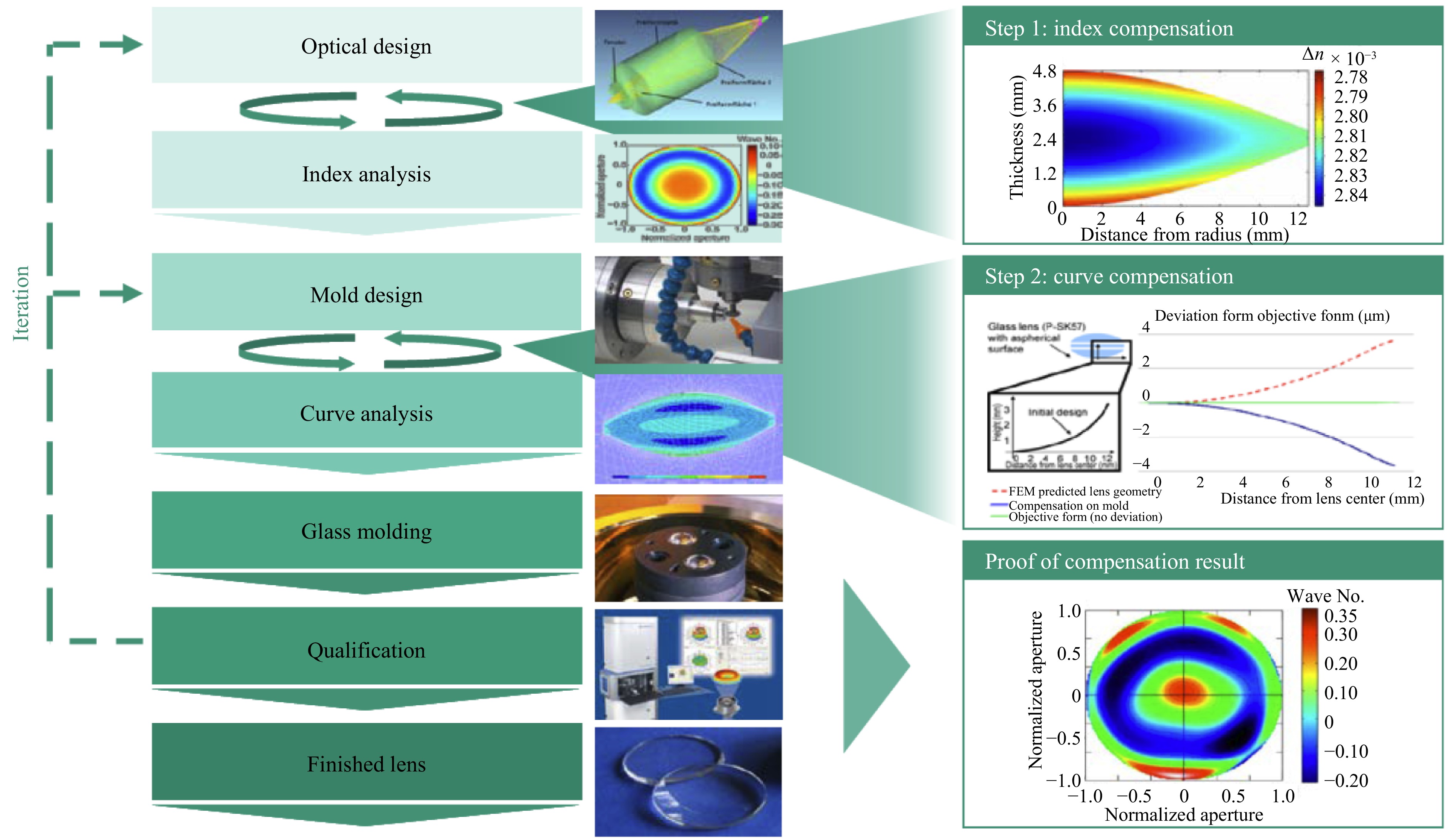
Fig. 26 Flowchart for an integrated compensation scheme96.
-
In this review, brief history, state of the art and the future of precision glass optics molding have been discussed in detail. As a relatively recent optical manufacturing process, in essence a fundamentally different optical fabrication process, glass molding has made substantial progress in its relatively short existence. Full scale implementation of the process in consumer products still depends on solutions to several key process issues but the potential of this technology is undeniably clear. Optical glasses significantly outperform plastic materials in both varieties and performances such that future optical designs will undoubtedly benefit from using more molded glass optics. Improvements in molding higher precision lenses and large size lenses will also open doors to both industrial and scientific applications. It is our intent to clearly outline the process such that it became readily available to both academic institutions and industrial users.
Although glass is amorphous but surprisingly thermodynamically many glasses are some of the most stable material forms. Glass structures follow highly precise paths during heating and cooling because of (high) viscosity, making glass molding ideal for precision lens fabrication. The fact that long range order does not exist in glass means that glass lacks the characteristics of a crystalline material such as clear melting point and lattice structures and these features inadvertently made glass an ideal material for molding imaging optical lenses where isotropic properties are essential. Glass does not have a distinguishing melting temperature, in glass material processing, instead, fictive temperature, a phenomenological parameter widely used to separate liquid and solid state of a glass under different cooling conditions. This temperature may vary slightly at different cooling rate and where cooling starts which plays an important role in modeling glass forming. This thermodynamic nature of glass materials is the fundamental reason for optical property variations in glass molding.
One of the process constraints of glass molding is the amount of thermal mass of a mold assembly, moving heat in and out of the mold assembly requires adequate heating and especially cooling to ensure glass is uniformly heated and cooling rate is managed to ensure acceptable residual stress and optical property changes. A typical industrial cycle time can easily exceed 20 minutes or longer, significantly increased manufacturing cost. To this end, fast heating and cooling of mold assembly can help reduce cycle time, sometimes substantially. For small optics, joule heating of micro and meso scale heaters have shown the possibility and benefits of a fast thermal cycle. More recently, a new surface coating utilizing carbon bonded graphene was evaluated for direct rapid heating of glass surface potentially can replace conventional complex mold assemblies that normally associated with large thermal mass, if implemented can significantly reduce molding cycle time.
Another approach to effectively shortening molding cycle time is somewhat indirect. Specifically, a process mimics wafer production in semiconduction industry. Glass wafers instead of glass gobs or preforms can be used. Mold inserts are machined using ultraprecision machining process. This approach reduces cycle time by forming a lens matrix simultaneously thus equivalent to molding high number of lenses sequentially with a much shorter time. This arrangement can be commercially viable providing optical industry with a real solution for micro and meso scale lenses for mobile applications, camera modules used in cars and offices.
Finally, industrialization of glass molding hinges on process optimization. In the future, Due to the nature of glass molding, particularly because glass molding itself is considered an ill posed problem since critical information inside glass lenses and mold surfaces cannot be measured directly and this information must be inversely acquired from measurements from sensors buried inside the mold assembly. It is reasonable to assume that machine learning and artificial intelligence assisted process optimization could be the future for fully implementation in consumer industry and scientific community. Other manufacturing processes such as sol gel-based glass optical fabrication, 3D printing have all demonstrated significant potentials to complement or in some cases completely replace glass molding, providing optical community with better products at lower cost. These exciting topics will be the subjects of future reviews.
-
Xiaohua Liu acknowledges the financial support from Department of Mechanical and Automation Engineering at CUHK and the Direct Grant for Research 2024/2025 from CUHK (Grant number 4055250). Jian Zhou acknowledges the financial support of the National Science Foundation of China (Grant number 52375179). Bo Tao was supported by the financial support of the National Science Foundation of China (Grant number 51505349).
Precision glass aspherical lens manufacturing by compression molding: a review
- Light: Advanced Manufacturing , Article number: 1 (2026)
- Received: 30 March 2025
- Revised: 22 October 2025
- Accepted: 03 November 2025 Published online: 19 March 2026
doi: https://doi.org/10.37188/lam.2026.001
Abstract: Precision aspherical lenses are in high demand for a wide range of industrial and consumer products. While plastic lenses have gained popularity for low cost and flexibility, glass remains the superior material for high-end optics for its exceptional optical properties. Glass molding is a modern manufacturing technique that offers both high precision and affordability. This review, aimed at both academic and industrial communities, provides a brief history of this technology followed by a detailed discussion of the fundamental physics and modeling involved in the molding process. The review also includes a brief discussion of optical design and forming equipment but focuses on the molding process. In addition to conventional methods, we also cover special molding techniques like rapid heating and wafer-level glass molding, as well as the molding of chalcogenide glass lenses. By examining key developments in material modeling, mold fabrication, heat transfer and process optimization, this review aims to support ongoing advancements for next-generation precision optical manufacturing processes.
Research Summary
Precision Glass Aspherical Lens Manufacturing by Compression Molding: A Review
Precision aspherical lenses are in high demand for a wide range of industrial and consumer products. While plastic lenses have gained popularity for low cost and flexibility, glass remains the superior material for high-end optics for its exceptional optical properties. This review, aimed at both academic and industrial communities, provides a brief history of this technology followed by a detailed discussion of the fundamental physics and modeling involved in the molding process. The review covers both conventional methods and special molding techniques like rapid heating and wafer-level glass molding, as well as the molding of chalcogenide glass lenses. By examining key developments in material modeling, mold fabrication, heat transfer, and process optimization, this review aims to support ongoing advancements for next-generation precision optical manufacturing processes.
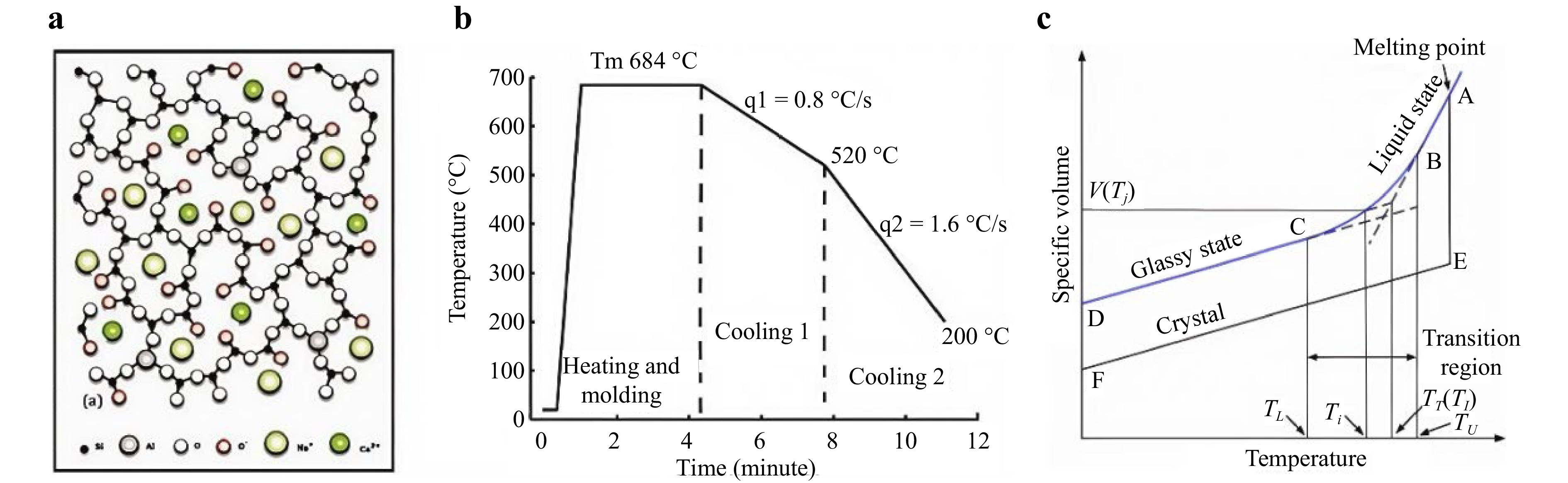
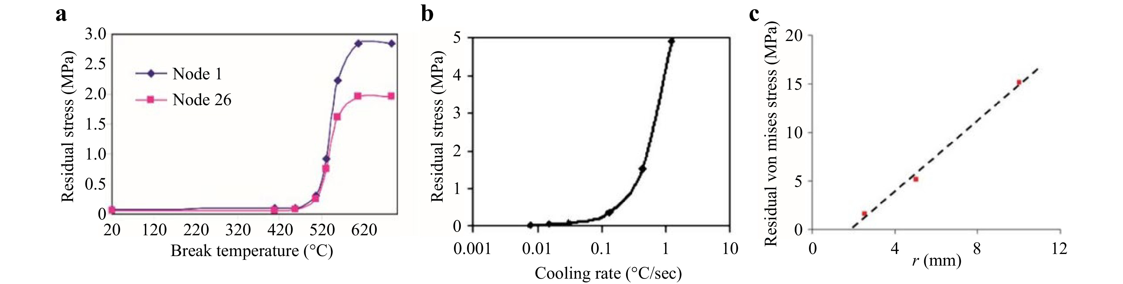
Rights and permissions
Open Access This article is licensed under a Creative Commons Attribution 4.0 International License, which permits use, sharing, adaptation, distribution and reproduction in any medium or format, as long as you give appropriate credit to the original author(s) and the source, provide a link to the Creative Commons license, and indicate if changes were made. The images or other third party material in this article are included in the article′s Creative Commons license, unless indicated otherwise in a credit line to the material. If material is not included in the article′s Creative Commons license and your intended use is not permitted by statutory regulation or exceeds the permitted use, you will need to obtain permission directly from the copyright holder. To view a copy of this license, visit http://creativecommons.org/licenses/by/4.0/.

 DownLoad: