


-
Silicon carbide (SiC) ceramic is regarded as one of the ideal materials for manufacturing high-performance space optical mirror, due to its extremely high specific stiffness (ψ), low coefficient of thermal expansion (CTE) and high thermal conductivity (TC)1–5. Currently, with the development of optical mirrors, a variety of complex structures have emerged with lightweight and functional characteristics, such as three-period minimal surface structure (TPMS)6, topology and lattice structures7,8, etc. However, despite the assistance of machining and molding, traditional techniques, such as pressure molding and slip casting, still face the technical bottleneck problem that it is impossible to prepare the above pre-designed complex structures9–11. Therefore, it is urgent to carry out technological innovations in the preparation of SiC mirrors in order to meet the development and requirements of space optical systems12–14.
Additive manufacturing, as a disruptive technology, can achieve the high-precision preparation of arbitrary structural ceramics without mold or machining15. Generally, SiC preform needs to be densified by reactive melt infiltration(RMI), after which SiC mirrors (Si/SiC) were obtained. At present, the common additive manufacturing technologies for preparing Si/SiC mirrors include vat photopolymerization (VPP)16,17, powder bed fusion (PBF)18, binder jetting (BJ)19 and material extrusion (MEX)20. VPP can prepare Si/SiC ceramics with high-precision and complex structures, but poor performance needs to be solved21. The rapid melting and solidification process caused by laser heating during PBF process is prone to cause deformation of components. In contrast to VPP, the Si/SiC prepared by MEX has excellent properties and low content of residual Si, but MEX is unable to prepare overhanging structures, curved structures, etc. Among these additive manufacturing technologies, BJ has developed rapidly in recent years due to its high precision and efficiency. However, high porosity and low density of SiC preform prepared by BJ needs to be solved. The porosities were filled with free silicon after RMI. As known, the properties (elastic modulus, flexural strength etc.) of Si are inferior to that of SiC5. Therefore, the insufficient properties of Si/SiC prepared via BJ remains a challenge due to high content of residual Si.
To promote the application of Si/SiC mirrors prepared by BJ and RMI. Many studies have proven the advancement of carbon precursor infiltration and pyrolysis (CPIP) method to decrease the content of residual Si18,19. The extra carbon was introduced into SiC preform by CPIP method, which can react with free Si during RMI process. Theoretically, the free Si can be completely eliminated by increasing the content of extra carbon. However, the large pores in SiC preform led to the aggregation of extra carbon, resulting in incomplete reactions and the formation of residual carbon. The residual carbon on the surface of mirror will form pores in situ after grinding and polishing, which will deteriorate the optical performance. Therefore, it is necessary to decrease the content and size of pores in SiC preform before CPIP process. During BJ process, the flowability of SiC powders determines the content and size of pores in SiC preform. Notably, She et al.22 proposed a molten salt method to prepare spheroidal SiC to improve the flowability of powders. The packing density of SiC powders was improved from 0.93 g/cm3 to 1.56 g/cm3. However, this method faces the challenge of ensuring health protection in an environment with strong alkaline corrosion. Additionally, Feng et al.23 proposed bimodal powder optimization method, which can reduce the size of pores between coarse SiC powders by the addition of fine SiC powders. The results showed that the density of SiC preform was increased by 31% than that of unimodal coarse powders. The current research mainly focuses on the shape and size of SiC powders, but lacks exploration of raw powders system design. The motivation of this study is to prepare Si/SiC with low content of free Si through composite raw powders optimization.
In this work, graphite addition method was proposed to increase the properties of Si/SiC. The graphite includes nanoscale graphite, microscale graphite, flake graphite and graphite fiber. On the one hand, graphite, as the lubricant, has excellent self-lubricating properties, which can promote the flowability of SiC powders during BJ process. On the other hand, graphite, as the carbon source, can promote the transformation of residual Si into secondary SiC during RMI process. Therefore, this work aims at revealing the effect of composite raw powders optimization method on the properties of Si/SiC ceramics. Additionally, the feasibility of preparing Si/SiC optical mirror by BJ additive manufacturing was systematically studied. From the virtual model to the three-dimensional entity, the properties, size changes and uniformity of the materials in each stage of the preparation process were evaluated for the first time so far.
-
The density and flowability test results of the raw powders are shown in Table 1. The porosity of SiC preform is sensitive to the flowability of the raw powders. Generally, raw powders with excellent flowability are beneficial for reducing the porosity. The Carr index is one of the key parameters for evaluating the flowability of powders, and the lower value indicates the better flowability. According to Eq. 1, Carr index is related to apparent density and tapped density of the powders24. As shown in Table 1, the addition of graphite could enhance the flowability of composite powders, excluding graphite fiber. The fibers/SiC composite powder demonstrates the highest Carr index, which was attributed to the low flowability caused by the rod-like shape of graphite fibers. By contrast, the flake graphite exerted a more effective lubricating function, which allowed the composite powders to attain the best flowability. Therefore, flake graphite was selected for the preparation of high-performance Si/SiC mirror, which is highly beneficial for minimizing the porosity of the SiC preform prepared by BJ technique.
Raw powders SiC fraction (wt.%) Apparent density (g/cm3) Tapped density (g/cm3) Carr index (%) SiC − 100% 1.023±0.009 1.681±0.014 39.14 SiC nanoscale graphite 99% 1.015±0.005 1.600±0.013 36.56 SiC microscale graphite 99% 1.053±0.009 1.594±0.007 33.94 SiC flake graphite 99% 1.100±0.013 1.601±0.006 31.29 SiC graphite fiber 99% 0.988±0.005 1.626±0.013 39.24 Table 1. Powder density and flowability of the raw powders.
$$ {\lambda} = \frac{{\rho }_{T}-{\rho }_{A}}{{\rho }_{T}} · 100{\text{%}} $$ (1) where λ refers to Carr index, ρA refers to apparent density, ρT refers to tapped density.
-
Fig. 1a, b demonstrate the microstructure of #1 (with flake graphite) and #0 (without graphite) preform. It is evident that the graphite was uniformly distributed in the #1 preform. It should be noted that the homogeneous dispersion of graphite in #1 facilitates the adequate reaction in the RMI process. The XRD patterns of #1 and #0 are shown in Fig. 1c, d. The (0 0 2) crystal plane of graphite corresponding to 2theta equal to 26.6 degree in #1 exhibits a distinct diffraction peak. In addition, XRD pattern of #1 and #0 show that the crystal structure of the raw powders was α-SiC (PDF#72-0018). As shown in Fig. 1e, the density, strength and modulus of the SiC preform were tested and analyzed. It is worth noting that the density of SiC preform was increased from 1.24 ± 0.21 g/cm3 to 1.34 ± 0.13 g/cm3 via the graphite addition method, which was due to the self-lubricating role of the graphite in the raw material powders. Lubrication of graphite between SiC particles promoted the raw powders to fill the pores during BJ process. It can be found that the content and size of the pores were decreased by the addition of flake graphite by the comparison between Fig. 1a, b. During RMI process, the pores in SiC preform were filled with residual Si. Therefore, the decrease of pores content facilitates to reduce the content of residual Si and enhances the properties of Si/SiC. At the same time, the error bar of #1 is smaller than that of #0, indicating that the addition of graphite improves the homogeneity of the SiC preform. The strength and modulus of the preform are mainly determined by the van der Waals forces between the binder and the SiC particles. It is worth mentioning that the SiC preform needs to have sufficient mechanical properties to meet the operation requirements before sintering. The primary limitation of BJ process is the low density of SiC preform. It is noteworthy that the binder presents a viable pathway to achieve the necessary performance for preform and meet the percolation threshold. During the BJ process, binder was sprayed onto the surface of the particles25, which enabled connections among SiC particles as shown in the enlarged view of Fig. 1b. Therefore, the flexural strength and elastic modulus of #0 SiC preform reached 2.71 ± 0.31 MPa and 23.5 ± 3.82 GPa. As for #1, the graphite addition improved the density of SiC preform, which reduced the pores between the SiC particles. As shown in Fig. 1e, the flexural strength and elastic modulus of #1 were improved by 7.41% and 8.33%, respectively. From the above results, graphite was uniformly distributed in #1. It can be seen that the properties of SiC preform was improved by the addition of graphite. During BJ process, graphite, as the lubricant, reduced the friction among SiC powders, which facilitated to reduce the content of residual Si after RMI process.
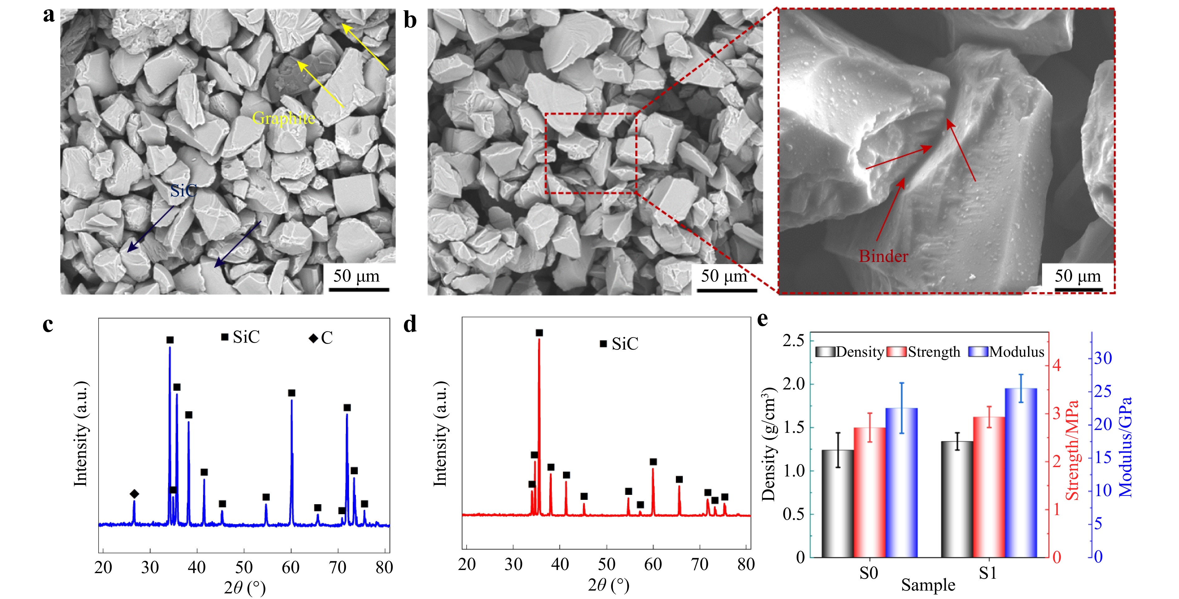
Fig. 1 Microstructure and properties of #1 and #0. a microstructure of #1. b microstructure of #0. c XRD pattern of #1. d XRD pattern of #0. e Properties comparison of #1 and #0.
-
Fig. 2 shows and compares the microstructures and components of all the specimens. During RMI process, the liquid Si penetrated the porous SiC preform and filled the pores. When the temperature dropped to room temperature, the dense Si/SiC was obtained. As shown in Fig. 2a, #0 was composed of Si (the light) and SiC (the dark). It is obvious that the content of residual Si was decreased after CPIP process, by the comparison between #0 and #0-CPIP in Fig. 2b. However, residual carbon was observed in the enlarged view of Fig. 2b, which would increase the porosity of the mirror surface after grinding. Compared with #0 preform, flake graphite carbon was added into #1 preform, which can be transformed into extra SiC. From the metallographic microstructure of #1 shown in Fig. 2c, the content of SiC in #1 is significantly higher than that in #0. It is worth noting that no residual carbon was observed in Fig. 2d. This indicates that the carbon in #1-CPIP had sufficiently reacted with liquid Si, even though the carbon content in #1-CPIP was 1 wt.% higher than that of #0-CPIP. In addition, the magnified view of Fig. 2d reveals numerous fine SiC particles, with sizes significantly smaller than those of the raw powders, confirming the formation of which via the Si-C reaction process. Therefore, the formation mechanism of residual carbon needs to be further investigated.
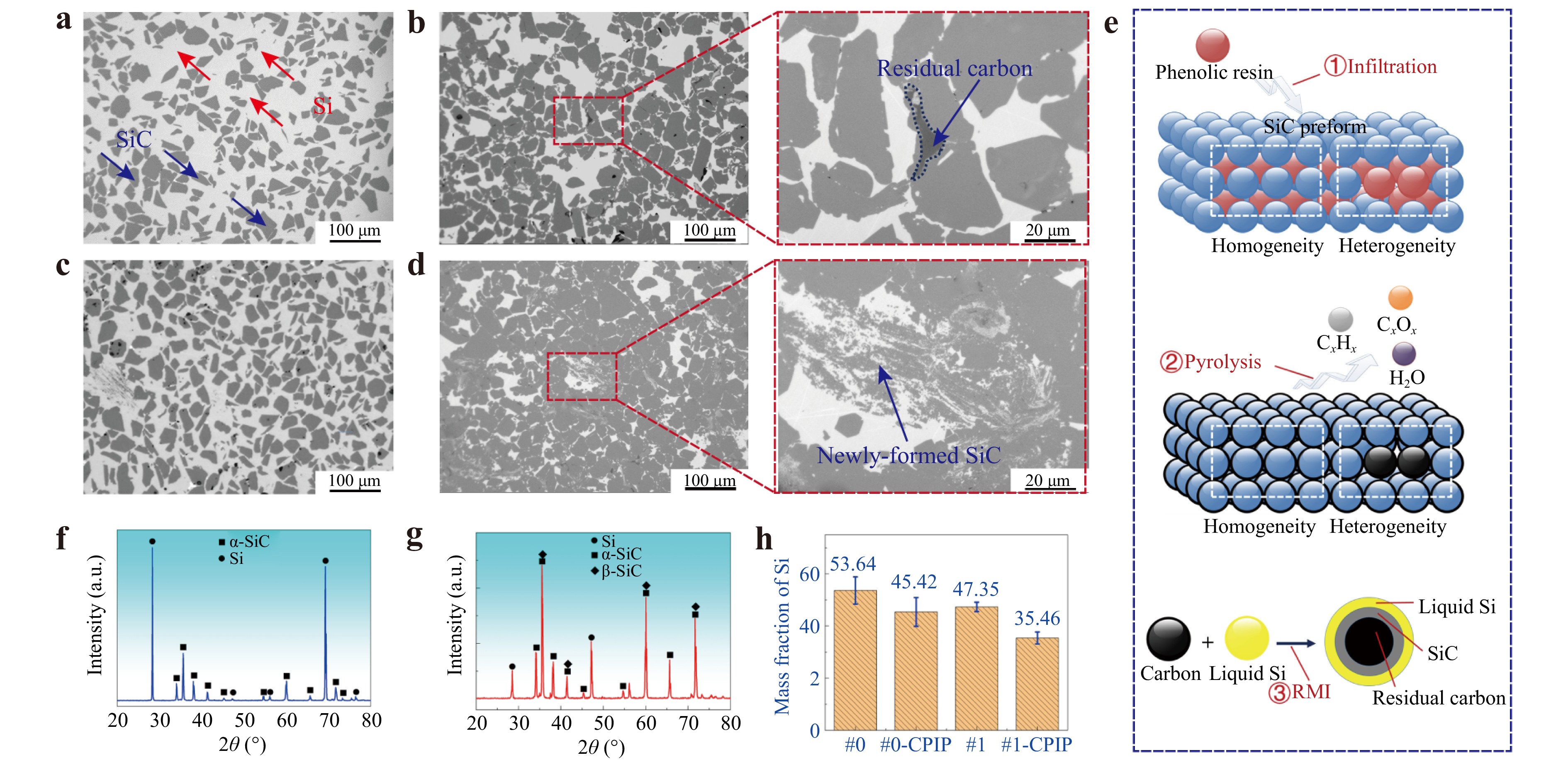
Fig. 2 Microstructure of Si/SiC. a microstructure of #0. b microstructure of #0-CPIP. c microstructure of #1. d microstructure of #1-CPIP. e the formation mechanism of residual carbon. f XRD patterns of #0 g XRD patterns of #1-CPIP. h residual Si content analysis.
The CPIP process involves infiltration and pyrolysis. As shown in Fig. 2e, phenolic (PF) resin, as the carbon precursor, was introduced into the SiC preform via infiltration process at room temperature. The distribution of PF was determined by the structure of SiC preform. It can be found that PF segregation preferentially occurred in heterogeneity areas of the preform. Then, the large-sized carbon is more likely formed in heterogeneity areas after pyrolysis in Fig. 2e. Finally, newly-formed SiC exits by the reaction between carbon and liquid Si. The newly-formed SiC precipitates on the surface of solid carbon, which is known as heterogeneous nucleation. As the reaction proceeds, a dense and continuous coating is formed on the surface of carbon, which isolates carbon from liquid Si and suppresses further reaction in Fig. 2e. This is the primarily mechanism for the formation of residual carbon in #0-CPIP. Therefore, the addition of flake graphite improves the flowability of the powders and enhances the uniformity of the preform, which is beneficial for the reaction between carbon and liquid Si. By the comparison of Fig. 2f, g, the crystalline type of the newly-formed SiC was β-SiC. Therefore, residual Si was effectively transformed into β-SiC with a fine diameter during high-temperature reaction under the action of the addition of graphite. As shown in Fig. 2h, it can be found that residual Si content was decreased from 53.64% of #0 to 47.35% of #1, which indicates that the residual Si was decreased by 6.29% via the addition of flake graphite. Moreover, the effect of CPIP process on the residual Si content could be inferred by the residual Si content of #1 and #1-CPIP in Fig. 2h. Theoretically, residual Si content could be decreased by 11.89% under the action of the carbon introduced by CPIP process. However, by the comparison between #0 and #0-CPIP, residual Si content was decreased by 8.22% due to the insufficient silicon-carbon reaction, which was less than the theoretical value of 11.89%. Hence, the addition of 1 wt.% flake graphite promoted the homogeneity of #1 preform and sufficient reaction between carbon and liquid Si.
Typical parameters used to evaluate the performance of Si/SiC mirror include density, flexural strength, elastic modulus, CTE and TC4. Compared with #0, #1-CPIP aims at improving the performance of SiC mirror by adding extra carbon in porous SiC preform. As known, the density of monocrystal SiC and Si is 3.21 g/cm3 and 2.33 g/cm3, respectively26–28. Fig. 3a depicts the density of Si/SiC, it can be seen that the density of Si/SiC was increased from 2.67 ± 0.04 g/cm3 to 2.83 ± 0.01 g/cm3. The high bending strength is advantageous for the mirror to resist vibration during transport or launch. In general, the flexural strength is related to SiC content, grain size, etc. Compared with #0, the flexural strength of #1 was increased from 243.87 ± 25.03 MPa to 268.37 ± 11.52 MPa as shown in Fig. 3a. According to Eq. 2 Hall-Petch formula, the formation of β-SiC with a fine grain size is one of the enhancement mechanisms in this work. Fig. 3b shows and compares the research status of SiC ceramics by BJ additive manufacture technique. As reported in Refs. 29-35, optimizing the process parameters is the foundation for the preparation of high-precision SiC ceramics. However, the flexural strength of SiC was generally below 230 MPa after the optimization of process parameters, as shown in Fig. 3b. Chaugule et al.32 reported that the flowability of raw powders was effectively improved via bimodal powders, which improved the flexural strength of SiC ceramics. In this work, flake graphite, as the self-lubricating phase, decreased the porosity of SiC preform during BJ process. In addition, flake graphite, as the carbon source, played a vital role in the transformation of residual Si to SiC during RMI process. Therefore, the flake graphite addition method endowed Si/SiC ceramics with excellent flexural strength in Fig. 3b.
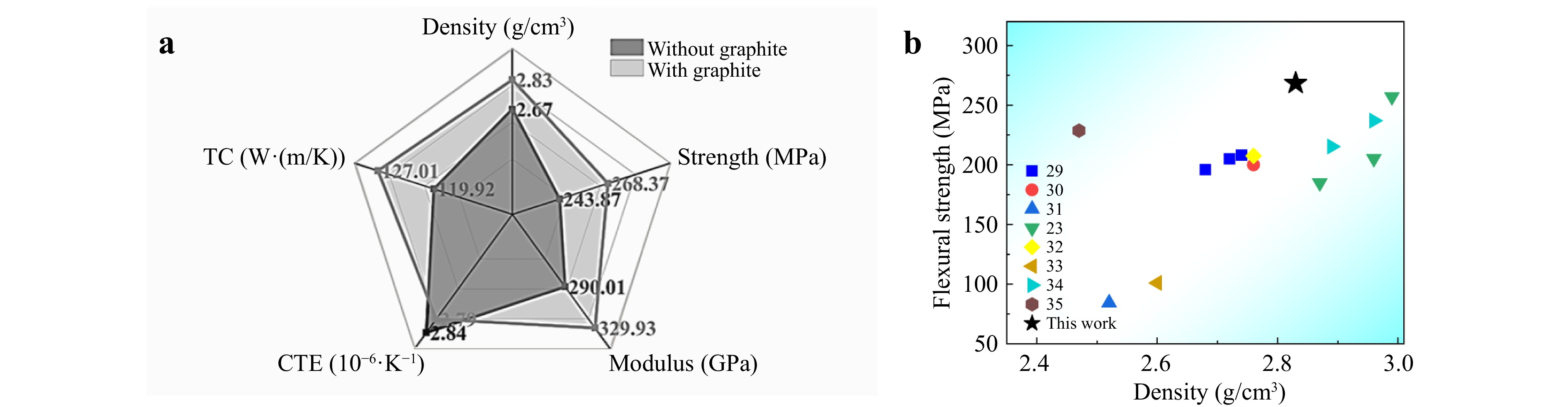
Fig. 3 Properties of Si/SiC. a comprehensive properties comparison of #0 and #1. b the research status of SiC ceramics based on BJ additive manufacturing.
$$ \mathrm{\sigma }_{ \mathrm{s}} \mathrm{=\sigma }_{ \mathrm{0}} \mathrm{+Kd}^{ \mathrm{-0.5}} $$ (2) Where σs is the strength, σ0 is the strength of maximum single crystal, K is the influence coefficient of grain boundary on deformation, d is the average grain size.
With the increase of modulus, the mirror is not prone to deform under the action of external forces, which plays a key role in maintaining good profile accuracy. As shown in Fig. 3a elastic modulus was improved from 290.01 ± 14.12 GPa to 329.93 ± 11.38 GPa via flake graphite addition method. The specific stiffness(ψ) is one of the key indicators for evaluating the service performance of optical mirror blank, which can be calculated by Eq. 3. It can be found that the ψ for #0 and #1-CPIP is 108.62 and 116.58, respectively. Therefore, the specific stiffness was increased by 7.33% via the graphite addition method, which is beneficial for maintaining the stable focal length of the mirror to obtain high-quality images. Table 2 compares the specific stiffness of Si/SiC prepared by BJ additive manufacturing process and traditional technique, it is worth noting that the Si/SiC obtained a comparable stiffness to that of traditional technologies through graphite addition method. This indicates that the Si/SiC prepared by this method is expected to meet the application requirements of space optical mirrors. The CTE represents the change of size with temperature. For high-end precision optical components, the CTE is essential to ensure the stability and accuracy of the optical system. As shown in radar map in Fig. 3a, the CTE of #1-CPIP is lower than #0, which is contributive to reducing the impact of size changes in a variable temperature environment, thus stabilizing the focal length and ensuring high-quality imaging. TC is another vital parameter to measure thermal dimensional stability of mirrors. The high thermal conductivity value is beneficial for achieving temperature equilibrium for the mirrors. Compared with Si, SiC has the higher thermal conductivity. Therefore, the TC of #1 is higher than that of #0. In summary, the comprehensive performance of the mirror can be improved by the addition of graphite.
Fabrication process Elastic modulus/
GPaDensity/
g·cm−3Specific
stiffnessRef BJ+RMI 330 2.83 116.61 This work BJ+RMI 294.67 2.95 99.89 22 BJ+RMI 300 2.87 104.53 27 BJ+RMI 243 2.66 91.35 28 BJ+RMI 256 2.74 93.43 29 Traditional technique 320-430 2.8-3.14 114-136 1 Table 2. Comparison of specific stiffness of Si/SiC prepared by BJ additive manufacturing and traditional technique.
$$ \mathrm{\psi =E/\rho } $$ (3) Where ψ refers to specific stiffness, E refers to elastic modulus (GPa), ρ refers to density (g/cm3).
-
Fig. 4 demonstrates the Si/SiC mirrors prepared via additive manufacturing and RMI process. Since Galileo invented the first telescope 400 years ago, the development of mirrors has gradually moved towards larger apertures to achieve higher resolution or weaker signal detection36,37. However, as the aperture increases, the mass of Si/SiC mirrors will increase accordingly, which will result in higher costs for the emission. Fig. 4a, b demonstrate the ability of BJ additive manufacturing technique for the preparation of Si/SiC mirrors with complex structure. As shown in Fig. 4a, Si/SiC mirror with triply periodic minimal surface (TPMS) was successfully fabricated by BJ. The traditional methods cannot prepare TPMS components even with the aid of machining or mold. In addition, Fig. 4b shows a topological Si/SiC mirror with a rib thickness of 1.09 mm. Machining process is difficult to prepare thin-wall structure, due to the hard and brittle properties of Si/SiC. The "edge collapse" phenomenon can be found inevitably by the intrinsic characteristic of SiC during machining. Therefore, BJ technology can break through the technical limitations of the traditional methods and give full play to the advantages of the structural design of the mirrors. Optical processing is one of the key steps during fabricating Si/SiC optical mirrors. Fig. 4c shows that the surface of Si/SiC mirror blank was grinded and there is no defect on the mirror surface. To obtain optical quality, a layer of silicon was applied to the Si/SiC substrate using physical vapor deposition (PVD) method. Fig. 4d demonstrates the schematic diagram of film thickness measurement. To measure the film thickness, a specimen identical to the Si/SiC mirror blank in its preparation process was produced. Before PVD, a layer of photoresist was coated on the surface of the specimen. After PVD, the film thickness was measured after removing the photoresist. Five measurement points were selected and the thickness were 12.25 μm, 12.18 μm, 12.29 μm, 12.29 μm and 12.64 μm, respectively. Therefore, the Si film with a thickness of 12.33 μm ± 0.16 μm was deposited onto the surface of Si/SiC mirror blank to ensure an excellent optical quality.
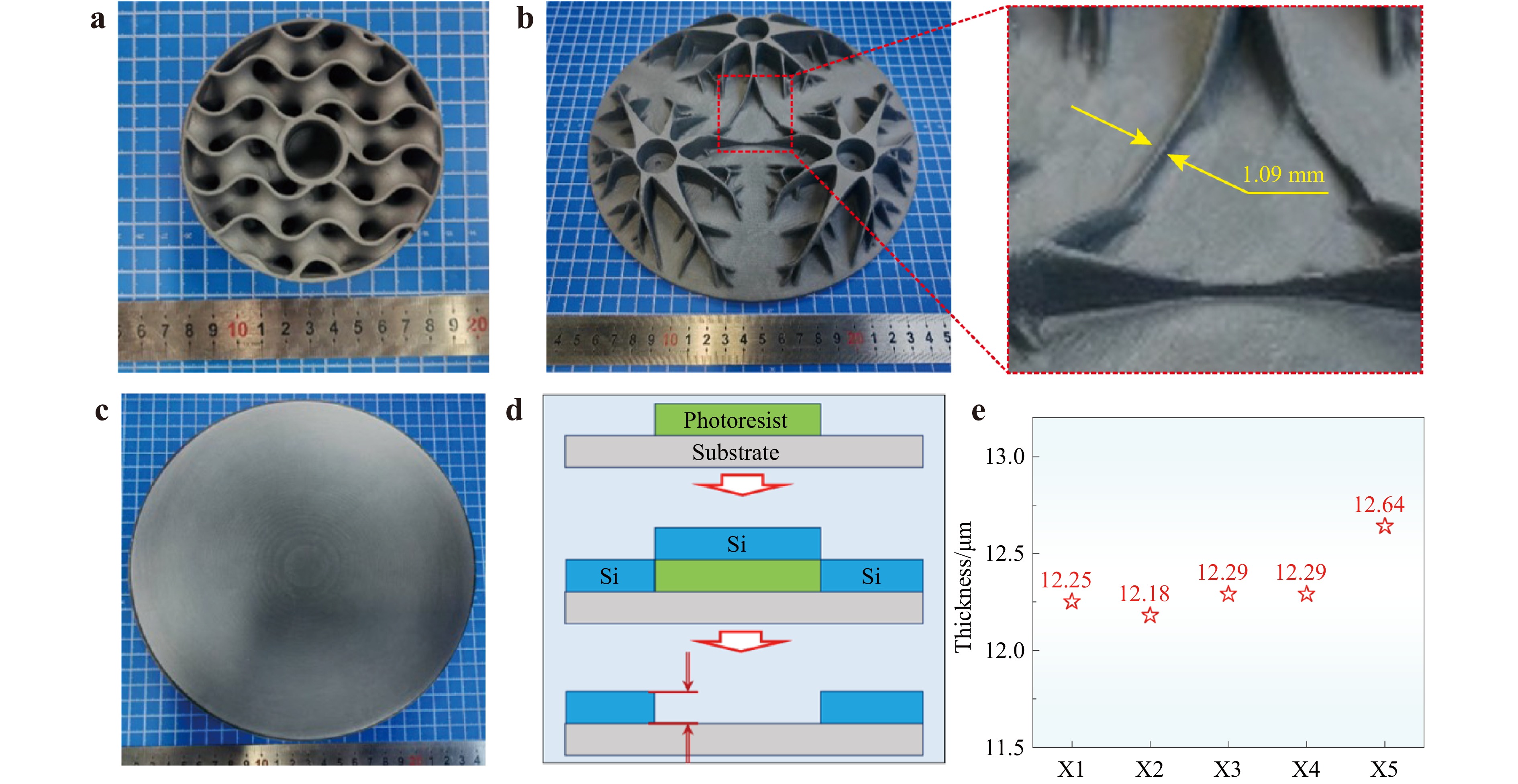
Fig. 4 Si/SiC mirrors fabricated via additive manufacturing. a Si/SiC mirror with TPMS structure. b Si/SiC mirror with topological structure. c after grinding. d schematic diagram of film thickness measurement. e measurement results for film thickness.
For the application of mirror, Si/SiC should possess excellent mechanical and thermal properties, coupled with remarkable optical properties. After polishing, Si/SiC mirror was shown in Fig. 5a. Fig. 5d demonstrates the shape accuracy was 12.05 nm RMS after optical processing, which was detected by Zygo interferometer. The surface roughness is one of the key performance parameters for evaluating the surface quality of optical mirrors. For traditional imaging optical system applications, the requirement for roughness is less than 3 nm38. Furthermore, for special applications such as high-power lasers or extreme ultra-violet, the roughness is usually required to be less than 1 nm38,39. In this work, the surface roughness reached 0.772 nm RMS (Fig. 5c), which indicated that Si/SiC mirror prepared by BJ additive manufacturing has wide-ranging applications.
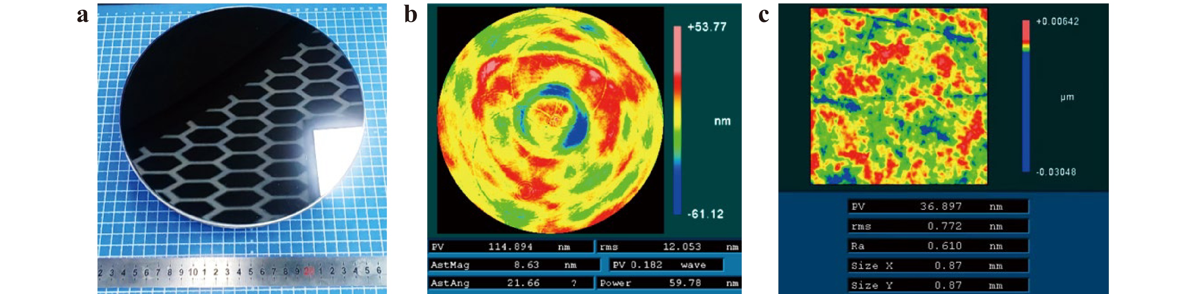
Fig. 5 Si/SiC mirrors. a after polishing. b surface shape accuracy. c surface roughness.
-
To meet the stability of focal length, optical mirror blank is required to have isotropic performance. Therefore, the homogeneity of mirror blank is one of the key indexes to evaluate the isotropic properties. Fig. 6a demonstrates the layout of cutting specimens from #1 porous SiC preform to measure the bulk density and apparent porosity, respectively. The mean value of density for #1 is 1.34 g/cm3. Fig. 6b shows the deviation of each sample from the mean value. The largest deviation is in S4, which is less than 1%. S5 has the lowest density, with a value 0.54% below average. As reported by Grinchuk1, the density deviation of porous SiC preform was less than 3%, which could ensure the mirror obtained an excellent optical surface after polishing. Therefore, the density deviation between S4 and S5 is 1.47%, which is acceptable. As shown in Fig. 6b, apparent porosity of SiC preform was measured by Archimides’ method. It can be seen that all samples have similar porosity, ranging from 45.56% to 47.81%. The extra carbon was introduced into porous SiC preform by CPIP. Similar porosity implies that the extra carbon in porous SiC preform has a homogeneous distribution after CPIP. Therefore, homogeneity of microstructure was obtained by the porous SiC preform, which stimulates the isotropic properties of SiC optical mirror.
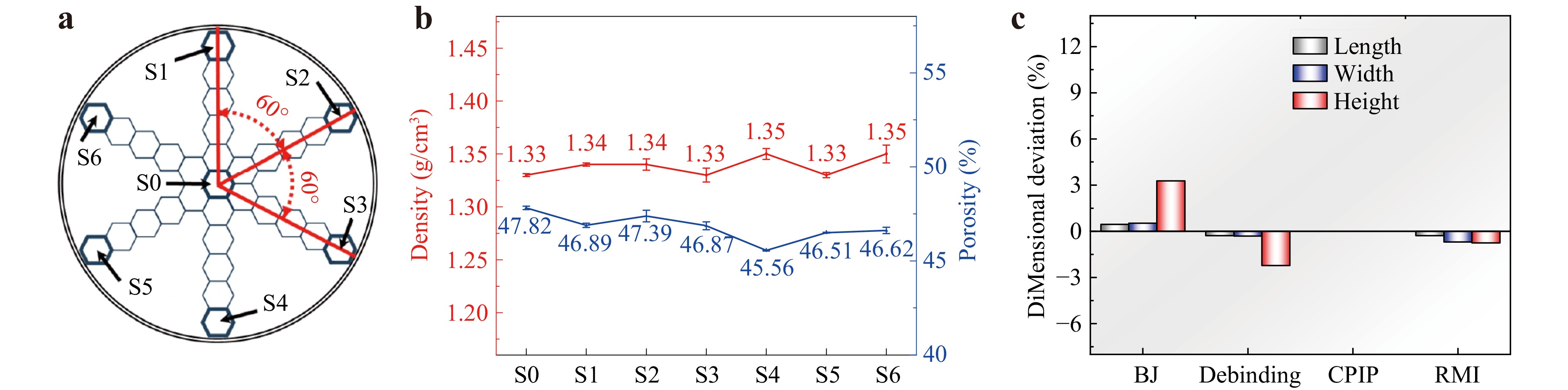
Fig. 6 Materials uniformity and dimensional stability analysis. a the layout of preform samples for materials uniformity measurement. b density and porosity of all the samples. c dimensional change during manufacturing process.
In general, excellent dimensional stability indicates high precision and low defects. Fig. 6c demonstrates the dimensional changes during the whole preparation process. During BJ process, the size accuracy of the SiC preform was determined by the permeation of binder. Generally, the binder would spread to the non-printing area under the action of permeation, causing the component size to increase. Therefore, the length, width and height were increased by 0.45%, 0.52% and 3.27% in Fig. 6c. During debinding process, the cured organics between raw powders were pyrolyzed at high temperature, and this process decreased the distance between particles. Therefore, debinding process results in the shrinkage of porous SiC preform compared to the model, such as the length, width and height were decreased by 0.28%, 0.32% and 2.23% (Fig. 6c). Fig. 6c shows that CPIP process has no effects on the dimensional change. Finally, dimensional shrinkage occurs during RMI process, such as the length, width and height were decreased by 0.28%, 0.70% and 0.76%, respectively. Therefore, compared the final product with virtual model, the dimensional deviation of the length, width and height was −0.11%, −0.49% and +0.28% after the whole preparation process. In addition, in order to obtain a complex structure mirror with high dimensional accuracy, the size (length, width and height) of the virtual model can be compensated according to the dimensional changes during the whole process.
As discussed above, the maximum density deviation of SiC preforms prepared by BJ additive manufacturing was 1.47% and the porosity of all the specimens ranged from 45.56% to 47.81%. These results suggest that SiC preform prepared by BJ obtained the excellent homogeneity, which is the key to preparing isotropic mirrors. In addition, the dimensional deviation of the length, width and height was −0.11%, −0.49% and +0.28% after the whole preparation process, as shown in Fig. 6c. Therefore, the SiC mirror with excellent shape accuracy was obtained by BJ combined with RMI technique.
-
This paper aims at proposing a method to improve the properties of SiC ceramics and evaluating the feasibility of BJ technique for the preparation of optical mirrors. Graphite addition method was used to enhance the carbon content of SiC preform during BJ process, which played a vital role in the improvement of Si/SiC ceramics. During the entire preparation process, SiC preform has good homogeneity with a negligible dimensional change, which is conducive for the isotropic properties of Si/SiC optical mirror. Specific conclusions are as follows:
(a) Optimization of composite powder components: Flake graphite proved most effective for lubrication due to its shape. The addition of flake graphite reduced the Carr index of the SiC powders from 39.14% to 31.29%. Therefore, flake graphite was selected for BJ process. The results showed that the addition of flake graphite increased the density of SiC preform from 1.24 g/cm3 to 1.34 g/cm3 and improved the homogeneity of #1 preform, thereby significantly promoting the complete reaction between Si and carbon.
(b) Properties enhancement mechanism of Si/SiC: During RMI, the β-SiC was formed via the reaction between carbon and liquid Si. Compared with #0-CPIP, residual carbon was eliminated in #1-CPIP, which demonstrated that graphite played a critical role in ensuring the complete reaction between Si and carbon. Therefore, the density was increased by 5.99% and residual Si was decreased by 18.18% via graphite addition method and CPIP process. Additionally, the flexural strength, elastic modulus and thermal conductivity reached 268.37 ± 11.52 MPa, 329.93 ± 11.38 GPa and 127.01 ± 4.31 W/(m−1·K−1), respectively.
(c) Optical properties analysis: Si/SiC mirror with complex structures, such as TPMS and topology, were fabricated. After optical processing, the shape accuracy and surface roughness of the RB-SiC mirror are 12.05 nm RMS and 0.772 nm RMS. Therefore, Si/SiC optical mirror by BJ additive manufacturing has the potential for applications in optical system.
(d) Preparation technique evaluation: After BJ process, the maximum density deviation of SiC preform was as low as 1.47% and all the specimens obtained consistent porosity ranging from 45.56% to 47.81%. Meanwhile, the dimensional deviation of the length, width and height was −0.11%, −0.49% and +0.28% after the whole preparation process. Therefore, BJ additive manufacturing combined with RMI process turns out to be a near-net-shape technique for the preparation of Si/SiC mirrors.
-
The preparation of silicon carbide mirrors mainly consists of five steps: (1) Composite powders optimization: different types of carbon were mixed with SiC powder to prepare composite powders with excellent flowability. (2) Additive manufacturing: SiC preforms with different components were obtained after BJ process. (3) Debinding sintering: the organics in SiC preform were removed by high temperature sintering, after which the porous SiC preform was obtained. (4) CPIP treatment: extra carbon was introduced into porous SiC preform to strengthen the properties of the preform and the final body. (5) RMI process: the content of newly formed SiC was increased at the expense of Si and extra carbon. During this step, the dense SiC final body was obtained after the pores of SiC preform was filled with Si. After grinding and polishing, SiC mirror with excellent reflectivity was obtained.
-
Four kinds of graphite with different shapes were used to prepare the composite powder. Fig. 7a, b show that graphite particles with different sizes (purity >99.95%, Shanghai Maclean Biochemical Technology Co., Ltd., China). As shown in Fig. 7c, the flake graphite (purity >99.95%, Shanghai Maclean Biochemical Technology Co., Ltd., China) has several tens of micrometers for length and width and less than 5 μm for thickness. The graphite carbon fibers (carbon content: 95%, Shanghai Pantian Powder Material Co.,Ltd., China) with a diameter of 7 μm and a length ranging from several tens to several hundred micrometers is shown in Fig. 7d. The SiC raw powder (purity >99.95%, Shandong Huamei New Materials Technology Co., Ltd., China) with the irregular shapes is shown in Fig. 7e, the mean diameter of which is 20 μm. In this work, composite powders were prepared by SiC powders and graphite with a mass ratio of 99:1. By exploring the influence of graphite shape on the flowability of the powders, the composite powder with the best flowability was selected for additive manufacturing.
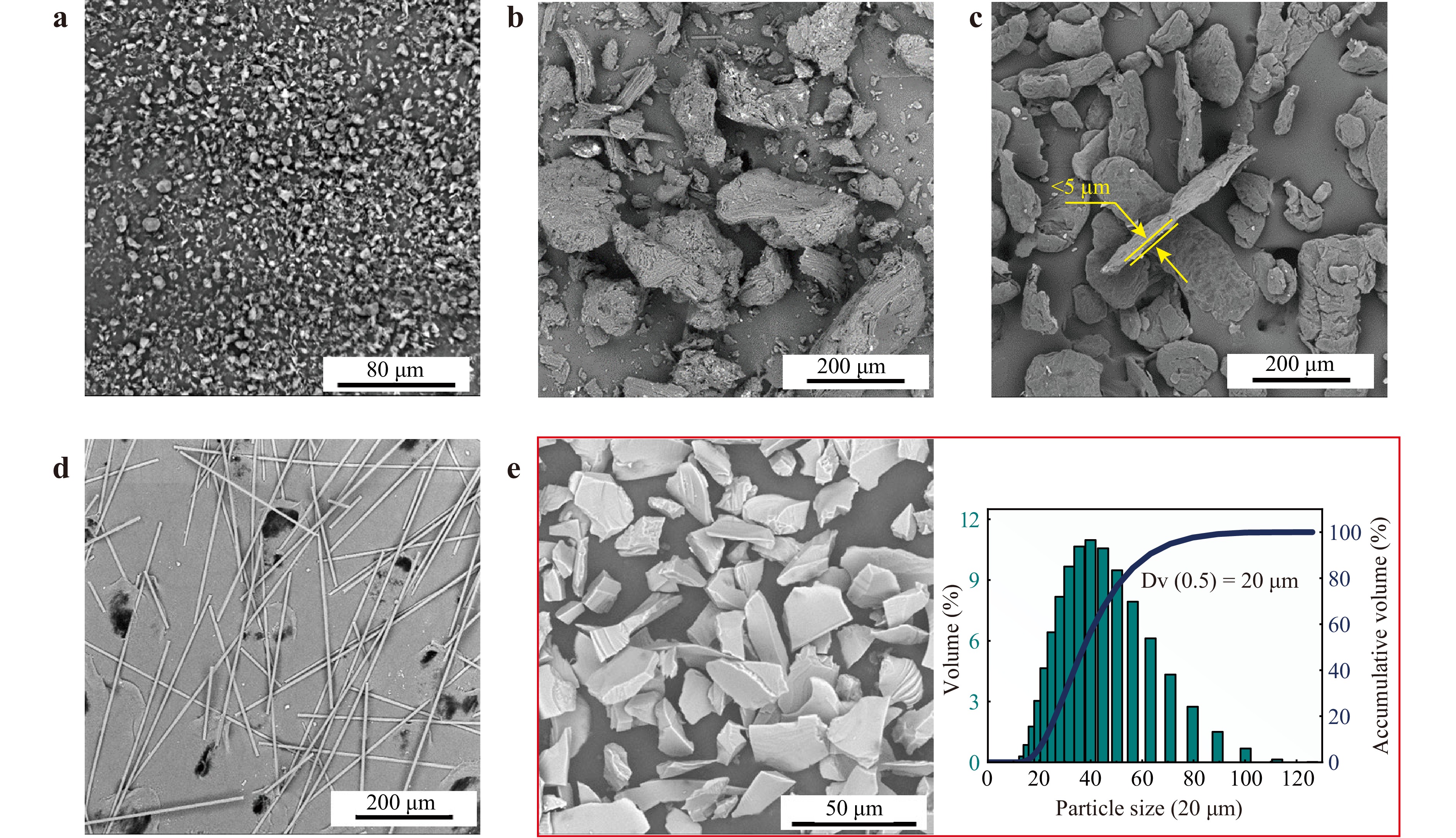
Fig. 7 SEM image for raw powders. a nanoscale graphite. b microscale graphite. c flake graphite. d graphite fiber. e SiC powders and size distribution analysis.
-
Compared with traditional methods, SiC mirror blank fabricated by BJ process has the advantages of short cycle, low cost and arbitrary structure. Fig. 8 demonstrates the flow chart of BJ process and the mirror blank with specific structure. First, the raw powders supply system rises together with the forming platform drops one layer thick, as shown in Fig. 8a. Second, the roller spreads a layer of raw material powders evenly, as shown in Fig. 8b. Thirdly, the print head selectively sprays the binder at a specific trajectory in Fig. 8c. Finally, the process of Fig. 8a-c is repeated until the end of the program, the SiC preform with specific structure was obtained. It is worth noting that the SiC preform needs to possess sufficient mechanical properties to ensure the integrity of the component during the subsequent operations. Table 3 shows the optimal printing parameters in this work. The sufficient properties were obtained after BJ printing, which can meet the requirement for liquid Si infiltration. In this work, the effects of raw powders composition on the properties of SiC mirrors were evaluated. When the raw material powder is α-SiC and graphite with a mass ratio of 99:1, the preform is named #1. To verify the effects of graphite on the content of residual Si, #0, as the standard group, was prepared without graphite.
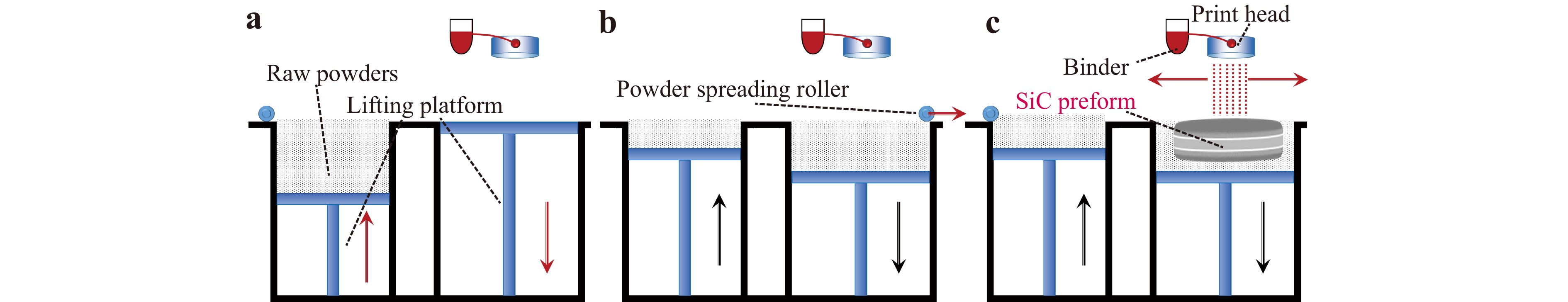
Fig. 8 Flowchart of BJ process. a raw powders supply. b spread powders. c selective spray binder.
Parameter Value Layer thickness 100 μm Roller Traverse Speed 19 mm/s Roller rotate speed 750 RPM Powder bed Drying Time 5 s Binder saturation 85% Table 3. Printing parameters used to prepare SiC preform.
-
The SiC preform consists of raw powders and cured organic matter. A large amount of gas is produced by the pyrolysis of organic matter at high temperature. The direction of gas escape is opposite to that of liquid silicon infiltration. Therefore, to ensure the densification of Si/SiC mirror, debinding sintering at 1500 °C for 30 min is performed before RMI process. After empirical exploration, the debinding process adopted in this study is shown in Fig. 9a.
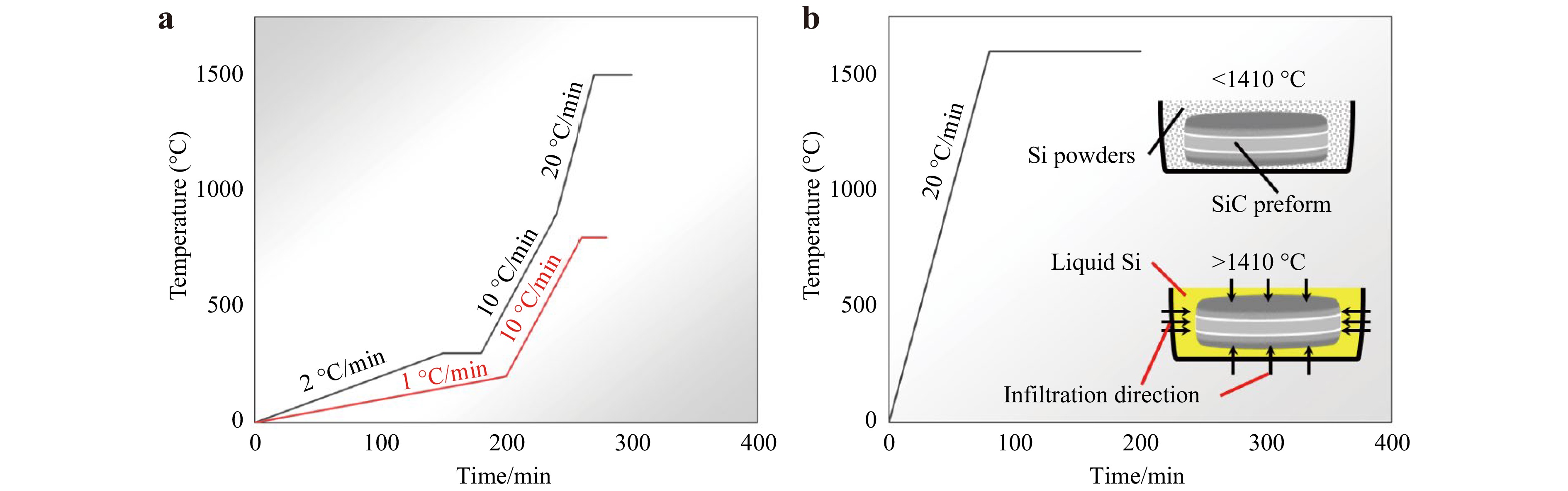
Fig. 9 Sintering process. a debinding and CPIP. b RMI.
-
CPIP is an essential step in the preparation of SiC mirrors. The phenolic (PF) resin (665, Changchun Shengda Insulation Material Co., Ltd, China), as the carbon precursor, was solved into anhydrous ethanol with a mass ratio of 1:1. First, SiC preform was immersed with PF solution at an ambient temperature for 2 hours in vacuum. Then, PF penetrated the SiC preform. Finally, PF in the preform was cured at 200 °C and pyrolyzed in situ at 800 °C to form extra carbon. The advantages of CPIP process mainly include increasing the strength and the carbon content of SiC preform. Generally, the flexural strength of SiC preform after BJ was less than 2 MPa, which is prone to cause cracks and collapse defects when the SiC preform is placed in the reaction sintering furnace. After CPIP process, the strength of SiC preform is improved effectively, thus ensuring the yield rate of the mirrors. Meantime, extra carbon was introduced into the SiC preform during this process, which is beneficial to boost the performance of the SiC mirror. To verify the effect of CPIP on the residual Si content, #0 and #1 are named #0-CPIP and #1-CPIP after CPIP treatment. The specific strengthening methods for each specimen in this study are summarized in Table 4. Therefore, by the comparison of #0, #0-CPIP, #1 and #1-CPIP, the coupling strengthening mechanism of addition of graphite and CPIP were revealed.
Group Strengthening methods Addition of graphite CPIP process #0 × × #0-CPIP × √ #1 √ × #1-CPIP √ √ Table 4. The specific strengthening methods for each specimen.
-
This is a key step to fabricating a dense SiC mirror. In the reaction sintering furnace, the SiC preform was embedded in a sufficient amount of Si powders in Fig. 9b. When the temperature rised above the Si melting point (>1410 °C), the liquid Si spontaneously melted into the SiC preform in Fig. 9b. The newly formed SiC was generated during the reaction process between liquid Si and extra carbon. Concurrently, the pores in the preform were filled with liquid Si. When the temperature in the furnace was cooled to room temperature, dense Si/SiC mirror blank was obtained. The variation of temperature over time during RMI is shown in Fig. 9b.
-
The microstructure of the preform and RB-SiC was observed by scanning electron microscope (SEM) equipped with energy dispersive spectrometer (EDS) (Phenom ProX, Netherlands) and optical microscope (BX51 M, Japan). Transmission electron microscopy (TEM) (Talos F200X, USA) was adopted to identify the crystal structure of the reaction products. The density and porosity of the preform and RB-SiC was measured based on the Archimedes’ principle. According to GB/T 4741–1999, three-point bending test was performed on mechanical testing machine (Instron 1195, USA) to evaluate the flexural strength. The specimens for three-point bending test were prepared with a size of 3 mm × 4 mm × 36 mm. The number of specimens were ten and the measurement results were averaged. Meanwhile, the elastic modulus is obtained by calculating the ratio of stress–strain curve in the elastic deformation stage according to Eq. 4. The coefficient of thermal expansion (CTE) is tested by linear dilatometer (DIL 402C, Germany) from 0 to 120 °C. The specimen was prepared with the size of 5 mm × 5 mm × 25 mm for CTE testing according to the Chinese Testing Standard GB/T 16535–2008. The thermal diffusivity and specific heat were tested by conductometer (LFA467Hyper Flash, Germany) and differential scanning calorimeter (DSC 214, Germany) at RT, respectively. Finally, the thermal conductivity was calculated by Eq. 5. The size of the specimens for thermal diffusivity testing is 12.7 mm for diameter and 2.5 mm for thickness. The size of the specimens for specific heat testing is 4 mm for diameter and 2 mm for thickness. It should be noted that in this experiment, the specimens used for performance testing were prepared separately, not cut from the mirror blanks.
$$ E = \frac{\sigma }{\varepsilon } $$ (4) $$ {\lambda =\alpha \cdot\rho \cdot c}_{ \mathrm{p}} $$ (5) Where stress (σ) is calculated by mechanical testing machine, strain (ε) refers to the relative change in length of the specimens in the direction of force, which is calculated as the change in length (ΔL) divided by the original length (L0), α and cp are the thermal diffusivity and specific heat, ρ is the density of the specimens.
-
This research was supported by Key research and development projects in high-tech fields (20260201076GX) and the Outstanding Young Scientific and Technological Talents Project of Jilin Province (20240602018RC).
Binder jetting additive manufacturing of high-performance silicon carbide optical mirrors via graphite addition method
- Light: Advanced Manufacturing , Article number: 25 (2026)
- Received: 08 July 2025
- Revised: 13 January 2026
- Accepted: 14 January 2026 Published online: 30 March 2026
doi: https://doi.org/10.37188/lam.2026.025
Abstract: Binder jetting (BJ) additive manufacturing demonstrates significant potential in the fabrication of silicon carbide composites (Si/SiC) mirrors with arbitrary structures. However, the insufficient performance of BJ-prepared Si/SiC, primarily due to high residual silicon (Si) content, limits its application. Here, graphite addition method was proposed to reduce the residual Si content through dual mechanisms. Performance enhancement mechanisms were revealed that graphite, as the self-lubricating phase, improves the flowability of raw powders, which facilitates to reduce the content and size of residual Si. Additionally, β-SiC was formed by the reaction of residual Si and carbon during reactive melt infiltration (RMI) process. The results show that the density of Si/SiC was increased by 5.99% and the residual Si content was decreased by 18.18%. Notably, the flexural strength, elastic modulus and thermal conductivity reached 268.37 MPa, 329.93 GPa and 127.01 W/(m·K), respectively. The dimensional deviations throughout the entire process were -0.11% in length, -0.49% in width, and +0.28% in height. Finally, high-performance Si/SiC mirrors with complex structure were fabricated. Furthermore, the shape accuracy and surface roughness of the Si/SiC mirror were 12.05 nm RMS and 0.772 nm RMS. Therefore, this work manifested the feasibility of graphite addition method for the performance enhancement of BJ additive manufacturing optical Si/SiC mirrors.
Research Summary
Mechanism for the properties strengthening of Binder Jetting Silicon Carbide
Binder jetting (BJ) technique demonstrates significant potential for the fabrication of silicon carbide (Si/SiC) mirrors with arbitrary structures. However, the insufficient performance of BJ-prepared Si/SiC, primarily due to high residual silicon (Si) content, limits its application. Recently, Ge Zhang’ team from Changchun Institute of Optics, Fine Mechanics and Physics, Chinese Academy of Sciences, proposed the graphite addition method. Here, Performance enhancement mechanisms were revealed that graphite, as the self-lubricating phase, improves the fluidity flowability of raw powders, which facilitates to reduce the content and size of residual Si. Additionally, β-SiC was formed along with stacking faults by the reaction of liquid residual Si and graphite carbon at high temperature. The team manifested the feasibility of graphite addition method for the performance enhancement of BJ-SiC optical mirrors.
Rights and permissions
Open Access This article is licensed under a Creative Commons Attribution 4.0 International License, which permits use, sharing, adaptation, distribution and reproduction in any medium or format, as long as you give appropriate credit to the original author(s) and the source, provide a link to the Creative Commons license, and indicate if changes were made. The images or other third party material in this article are included in the article′s Creative Commons license, unless indicated otherwise in a credit line to the material. If material is not included in the article′s Creative Commons license and your intended use is not permitted by statutory regulation or exceeds the permitted use, you will need to obtain permission directly from the copyright holder. To view a copy of this license, visit http://creativecommons.org/licenses/by/4.0/.

 DownLoad: