


-
Astronomy is, at its core, an empirical science grounded in observation. Since the early 17th century, when Galileo first pointed his handmade optical telescope toward the heavens and discovered phenomena such as the moons of Jupiter and the craters on the Moon, the boundaries of human knowledge about the universe have been deeply intertwined with the observational capabilities of telescopes. This model of technological advancement driving cognitive progress has been repeatedly demonstrated throughout the more than 400-year history of astronomy. From the perspective of optical theory, the angular resolution θ of a telescope is determined by the classical Rayleigh criterion, expressed as θ = 1.22λ/D, where λ is the observation wavelength and D is the telescope aperture. At the same time, the light-gathering power of a telescope is proportional to the area of its aperture, meaning it scales with the square of the aperture D. These two physical principles form the fundamental driving force behind telescope development: the pursuit of higher spatial resolution and the ability to detect fainter signals directly translates into a continuous demand for larger-aperture optical systems1,2.
Driven by this imperative, telescope apertures have evolved from the few centimeters of Galileo’s telescope, to the 1.2-meter metal mirror crafted by William Herschel in the 19th century, to the 5-meter Hale telescope in the 20th century, and further to modern apertures of the 10-meter class. Fig. 1 illustrates the global distribution of major astronomical telescopes, including representative facilities such as the Keck Telescopes in Hawaii, USA; the Very Large Telescope (VLT) at Paranal Observatory, Chile, operated by the European Southern Observatory (ESO); among others3. Numerous review papers have offered comprehensive summaries and analyses of crucial topics related to astronomical telescopes, including optical design4,5, site selection6,7, substrate materials3,8, structure design9,10, manufacturing processes11–13, and acceptance tests14. However, while physical laws provide the impetus for this progression, they also impose constraints. According to the theory of elasticity, under uniform support conditions, the bending deformation of a mirror due to its own weight is proportional to the cube of its aperture (D3). Even more critically, empirical evidence suggests that the manufacturing cost of large optical projects scales approximately with the aperture raised to the power of 2.7 (D^2.7). These formidable physical and economic barriers collectively indicate that the traditional monolithic mirror technology path is approaching its asymptotic limit, spurring a revolution in manufacturing paradigms for the next generation.
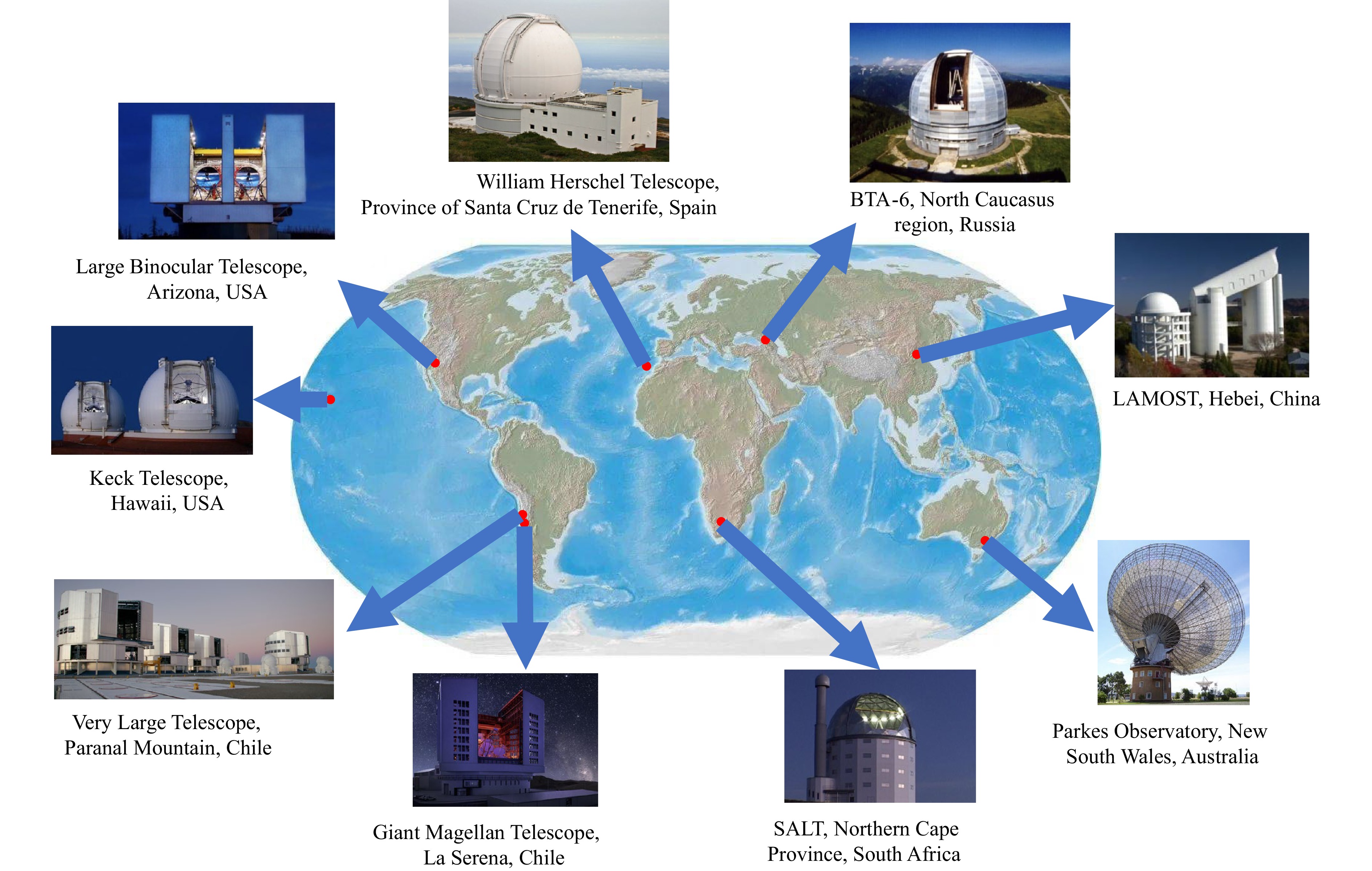
Fig. 1 Global distribution of leading astronomical telescopes3.
-
The manufacturing engineering of modern giant telescopes has evolved from an early stage focused solely on achieving surface figure accuracy (e.g., reaching λ/50 RMS, λ=632.8 nm) into a complex systems engineering problem seeking Pareto optimality under multiple constraints. Its core challenges can be systematically summarized into the following three interrelated dimensions:
Lightweighting challenge: To effectively reduce the burden on the support structure and significantly lower launch costs for space telescopes, the areal density (mass per unit area) of the mirror itself must be drastically reduced. Contemporary advanced telescopes typically require an areal density below 200 kg m−2, with next-generation conceptual designs aiming for targets as low as 100 kg m−2. This demand has spurred the development of complex back-open honeycomb, triangular mesh, or composite sandwich structures. However, while achieving weight reduction, this lightweight design introduces new manufacturing difficulties, most notably the “print-through” effect during polishing. This occurs due to insufficient panel stiffness, causing the structural pattern of the support ribs to be replicated as a detectable imprint on the optical surface.
Thermal stability challenge: Ground-based telescopes must cope with diurnal cycles and seasonal temperature gradients, while space telescopes operate in extremely cold environments. In this context, the coefficient of thermal expansion (CTE) of the material becomes a decisive parameter. Ideal optical materials require dimensional change ΔL L−1 to approach zero within their operational temperature range to avoid “thermal blurring” effects and surface figure distortion caused by thermal deformation, thereby ensuring the fidelity of observational data.
Full spatial frequency error control challenge: This modern concept treats the optical surface as a two-dimensional spatial frequency domain signal, requiring precise control over all surface deviations from the macroscopic to the microscopic scale: 1. Low-frequency errors (Spatial wavelength > 10 mm): Primarily affect the system’s wavefront error, directly determining the Strehl ratio of the image quality and the core energy concentration of the point spread function (PSF). This is the primary metric for evaluating the imaging capability of an optical system. 2. Mid-frequency errors (Spatial wavelength between 1 mm and 10 mm): Cause small-angle scattered light, forming a scattered “halo” or “wings” around the PSF. This significantly reduces the signal-to-noise ratio for high-contrast observation targets, posing a critical constraint for cutting-edge fields like direct imaging of exoplanets and protoplanetary disk studies. 3. High-frequency errors / Surface roughness (Spatial wavelength < 1 mm): Primarily affect the mirror’s scattering properties and reflectivity. Scattering losses induced by micro-roughness are particularly significant in the ultraviolet and X-ray bands, directly impacting the system throughput.
-
To fundamentally transcend the size limitations inherent to monolithic mirrors, segmented primary mirror technology has emerged as a profound systems revolution, far beyond a mere assembly technique, deeply integrating precision manufacturing, active optics, and nanometer-level phase control15. This paradigm, validated from the Keck telescopes to the forthcoming TMT (492 segments) and ELT (798 segments), has fundamentally redefined manufacturing objectives from crafting a “single, perfect large-aperture mirror” to the batch production of hundreds of highly consistent, off-axis aspheric segments. This shift has, in turn, systematically introduced new, profound challenges: the phasing problem, requiring the optical path difference from all segments at the focal plane to be stably maintained below λ/20, imposing nanometer-level demands on segment edge design, alignment, and actuator control; the consistency problem in mass production, necessitating manufacturing processes with exceptional repeatability, stability, and control to keep all segments within a strict performance tolerance band; and the efficiency and cost problem, mandating a revolution away from traditional, years-long polishing processes toward highly efficient, parallelizable manufacturing flows to render future ultra-large aperture telescopes feasible in both timeline and budget.
-
This review is situated within the aforementioned technical context and core challenges. Following the natural workflow of mirror manufacturing, it constructs a logically rigorous, step-by-step discussion framework. First, we will delve into the mirror substrate material systems as the foundation of everything, systematically analyzing how the physical and mechanical properties of different materials collectively determine the performance ceiling of the final system. Next, we will focus on precision shaping technologies (primarily encompassing ultra-precision machining and grinding), detailing how these technologies efficiently and accurately transform raw material blanks into optical near-net-shapes that meet design specifications. Subsequently, the paper will concentrate on the final finishing stage (covering various advanced polishing technologies), seen as the final battlefield decided at the nanoscale. The choice of technical path here directly determines the final quality of the mirror surface and its full spatial frequency error levels. Finally, based on a systematic comparison and synthesis of the complete technological chain, we will summarize the current convergence trends in technological development and outlook potential future research directions and development paths likely to achieve key breakthroughs. Through this structured analysis, this review aims to provide a comprehensive and in-depth technical reference framework for the design and manufacturing of future extreme optical systems.
-
Mirror materials form the foundation of optical systems and define the physical basis and performance boundaries of mirror manufacturing. The selection process is a complex optimization search within a multidimensional constraint space. An ideal mirror material must achieve an optimal balance among the following seemingly contradictory performance indicators, which we refer to as the “five-dimensional performance metrics”16:
1. Coefficient of thermal expansion: Must remain extremely low and stable across the entire operational temperature range of the telescope, typically requiring performance better than ±0.1 × 10⁻⁶ K−1.
2. Specific stiffness (Elastic Modulus/Density): High specific stiffness ensures minimal deformation under self-weight, wind loads (for ground-based systems), or launch loads (for space-based systems), while also facilitating lightweight design.
3. Density: Directly influences the total weight of the mirror assembly, critically impacting the support system design and launch costs.
4. Thermal diffusivity: Reflects the material’s ability to equalize temperature. A high value enables rapid dissipation of absorbed radiant heat, thereby reducing thermal-induced distortions in the mirror.
5. Manufacturability: Includes factors such as castable/sinterable dimensions, grindability, polishability, and the depth of subsurface damage after processing. These aspects directly determine manufacturing feasibility, production cycle time, and cost.
Materials Density (g cm−3) Elastic modulus (GPa) Thermal expansion coefficient (10−6 K−1) specific stiffness (106 m2 s−2) Thermal diffusivity (10−6 m2 s−1) SiC 3.04 330 2.4 112 75 Beryllium 1.85 287 11.3 155 60 Aluminum 2.7 68 22.5 25.2 97 Zerodur® 2.53 92 −0.09 36.4 0.8 Fused silica 2.19 73 0.5 33.3 0.53 Table 1. Comparison table of the astronomical mirrors’ key material parameters16
-
Glass is one of the most common materials used for astronomical mirrors. It has a low thermal expansion coefficient, is easy to fabricate, and can achieve high surface accuracy and smoothness. However, glass is fragile and has low strength, necessitating thicker mirrors with higher mass, which increases the requirements for mounting fixtures. Glass mirrors are also susceptible to damage during transportation and installation, limiting their size. Additionally, glass mirrors are vulnerable to external influences during use17.
ZERODUR is a type of glass-ceramic material that has been successfully used in the substrates of astronomical telescope mirrors for 40 years. This material is renowned for its extremely low coefficient of thermal expansion and high mechanical stability, making it an ideal choice for large modern optical telescopes. ZERODUR® consists of nanometer-sized crystals embedded in a glassy phase, which account for 70% to 78% of its weight. These nano crystals are formed through a special thermal treatment process known as ceramization. The material has a thermal expansion coefficient that is nearly zero at room temperature, with an accuracy typically ranging from 0 ± 20 ppb K−1. ZERODUR® also features excellent optical homogeneity, low internal stress, and superior polishability. SCHOTT began the material development of ZERODUR® in 1966 and accepted an order from the Max Planck Institute in 1968 to produce eleven mirror substrates, including one with a diameter of 3.6 meters. After nine years of development, ZERODUR® was successfully manufactured and put into operation in 1984 at Calar Alto, Spain. ZERODUR® has been utilized in several major telescope projects, including the Very Large Telescope (VLT) of the European Southern Observatory, the Keck Telescope, and the X-ray observatory CHANDRA. The application in X-ray astronomy is particularly demanding. Due to their short wavelengths, X-rays are extremely sensitive to mirror surface roughness, as even nanoscale imperfections can cause significant scattering and degrade imaging performance. This imposes stringent requirements on mirror materials and their finishing processes. X-rays have a refractive index close to 1 in most materials, indicating that refractive systems are unsuitable for X-ray wavelengths. The CHANDRA X-ray telescope is an X-ray astronomical satellite launched by NASA, named after the renowned astrophysicist Subrahmanyan Chandrasekhar. At the heart of CHANDRA is a high-resolution mirror system made from ZERODUR® glass-ceramic. Fig. 2a illustrates the manufacturing process flow diagram for these ZERODUR®-based astronomical mirrors. The CHANDRA telescope offers much higher resolution and sensitivity than its predecessors3.
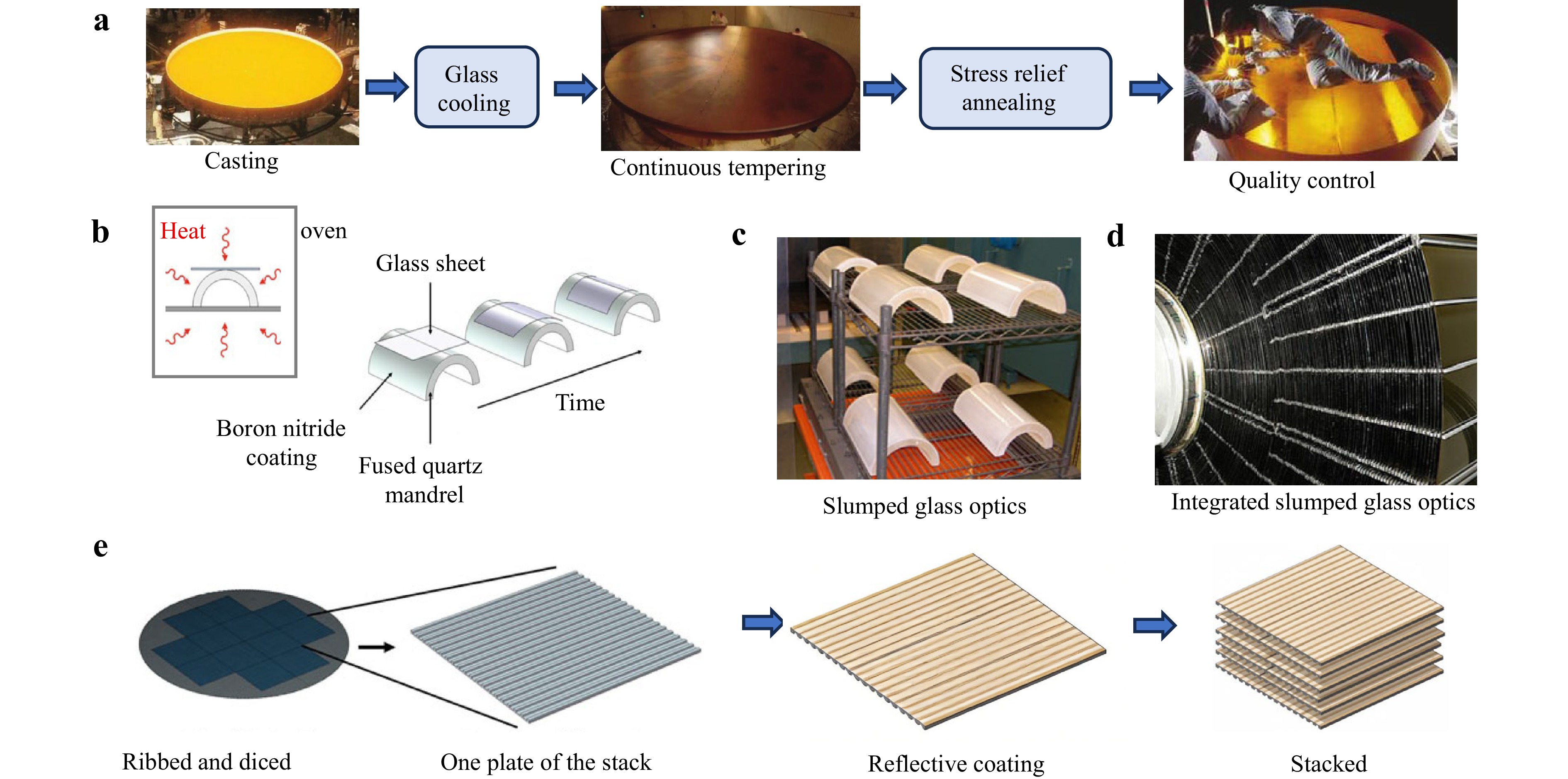
Fig. 2 a Manufacturing process flow of ZERODUR astronomical mirror. Reproduced with permission19. Copyright 1963, SPIE. b A schematic of the slumping process. Reproduced with permission18. Copyright 2024, Springer Nature. c Slumped glass optics formed upon the fused quartz mandrel. Reproduced with permission18. Copyright 2024, Springer Nature. d The integrated slumped glass optics within the Wolter Type I X-ray space telescope mirrors. Reproduced with permission18. Copyright 2024, Springer Nature. e Manufacturing process of silicon hole optical X-ray optical system. Adapted with permission18. Copyright 2024, Springer Nature Singapore.
To meet the exceptional smoothness requirements for X-ray reflection, borosilicate glass, due to its excellent optical properties and low coefficient of thermal expansion, is widely used in the manufacture of Wolter Type I X-ray space telescope mirrors. This material provides good optical homogeneity, and through precise slumping processes, mirrors with specific curvatures can be made to meet the reflection needs of X-rays at very small angles of incidence. The slumping process involves placing thin glass sheets on a mold, heating them to the glass transition temperature, and using gravity to make them conform to the mold surface to form the required shape. This process is cost-effective and time-efficient, and has been used to manufacture the flight optical systems for the NuSTAR mission. As shown in Fig. 2b, c , the molds are typically made from fused silica, polished, and then cut in half to create two semi-cylindrical molds. Pre-cut and cleaned glass sheets are placed on the molds and heated to about 600°C, the glass transition temperature, making the glass pliable and conforming it to the shape of the mold. The shaped glass sheets are then inspected and proceed to the next steps for X-ray reflective coating and integration processing. As shown in Fig. 2d, for missions such as NuSTAR, a complete telescope mirror system is formed by integrating and assembling multiple individual glass sheets18.
-
Silicon Pore Optics (SPO) is an innovative manufacturing technology for X-ray optical systems that fully leverages mature silicon wafer processing techniques from the semiconductor industry, as shown in Fig. 2e. At its core, the technology utilizes 300 mm diameter double-sided super-polished silicon wafers (surface roughness < 1 Å RMS) as base materials, which are precisely processed into plates with ribbed support structures through advanced photolithography and etching techniques. These silicon plates undergo chemical etching to form precisely shaped wedge-like reflective surfaces, followed by deposition of X-ray reflective coatings (such as gold or iridium), while keeping the ribbed areas clean for subsequent bonding18.
During manufacturing, each silicon plate undergoes pre-bending to achieve the required parabolic or hyperbolic curvature in the radial direction. These plates are then stacked layer-by-layer on high-precision silicon molds using an innovative hydrophilic bonding technique. This bonding process begins with hydroxylation treatment to create temporary van der Waals forces between silicon surfaces, followed by annealing to form permanent covalent bonds, completely eliminating the need for traditional adhesives. The completed SPO modules feature a unique pore structure, where precise alignment of two modules along the optical axis forms a standard Wolter-I type X-ray optical system.
The technology offers remarkable advantages: ultra-lightweight design (mirror thickness < 1 mm), high rigidity (benefiting from silicon’s high Young’s modulus of 160 GPa), excellent thermal stability (due to silicon’s low thermal expansion coefficient of 7.5 × 10⁻⁶ K−1), and suitability for automated mass production. Currently, SPO technology has been selected by the European Space Agency for the “Athena” X-ray Observatory project (scheduled for launch in the 2030s), aiming to achieve 5 arcsecond angular resolution and 1.4 square meters of effective collecting area.
However, the technology still faces several key challenges: maintaining stacking alignment accuracy within 1 micron between layers, precise management of residual stresses during manufacturing, ensuring uniformity of X-ray reflective coatings, and the lack of long-term reliability verification in space environments. Future research will focus on optimizing automated intelligent manufacturing processes, developing new bonding technologies, and creating more durable X-ray reflective coatings to further enhance SPO’s performance and reliability, meeting the increasingly demanding requirements of future X-ray astronomical observations.
-
Metal mirrors have a higher thermal diffusivity compared to glass, allowing them to achieve thermal equilibrium more quickly in space, thereby improving observational efficiency and precision. High thermal diffusivity also suppresses mirror edge effects and reduces spherical aberrations caused by uneven thermal diffusion. Metal mirrors are generally easier to repair if damaged compared to glass mirrors.
-
Aluminum is one of the most common metals on Earth, with well-established processing techniques and strong operability. It has high specific stiffness and thermal diffusivity, is lightweight, and has low hardness. Due to these excellent properties, aluminum alloys are widely used in astronomical mirrors. However, common aluminum alloy substrates are challenging to polish to high precision, so typically, a Ni-P coating is applied to the aluminum alloy mirror surface. The Ni-P coating has good cutting and polishing properties, achieving the required optical surface roughness.
The Ariel telescope mirrors utilize 6061-T651 aluminum alloy. This alloy is based on aluminum, with primary additions of silicon (Si) and magnesium (Mg) to enhance its strength and corrosion resistance. The aluminum alloy has a low density (2.7 g cm−3), good machinability, and excellent weldability. Due to its lightweight and thermal stability, this aluminum alloy material is highly suitable for the manufacture of space telescope mirrors. However, because of the low density of aluminum alloy, it is subject to stress from its own weight, launch operations, and mechanical processing (such as cutting, diamond turning, and polishing) during manufacturing and launch20.
These stresses accumulate within the machined piece and are gradually released over time, leading to changes in shape and roughness, which in turn cause deformation of the mirror and potentially take the surface out of specification. Since Al6061-T651 aluminum alloy is produced through a rolling process, it contains Si-Mg aggregates resulting from the heating and cooling during rolling, with sizes up to about 1 micrometer, affecting the polishing of the optical surface. Aggressive polishing to improve shape may peel off these aggregates, leaving holes that cause diffuse opacity over the entire surface and a significant increase in roughness. To address these risks and shortcomings, Guerriero Elisab and colleagues from various Italian research institutions have developed a heat treatment process, including solution treatment, quenching, aging treatment, and uphill quenching, to enhance the performance and stability of the aluminum alloy mirrors. The main heat treatment process is shown in Fig. 3a. Two thermal cycles are performed before and after processing the optical surface to release the stress accumulated by mechanical processing. Through heat treatment, the internal stress of the aluminum alloy is released, improving the material’s thermal stability. The hardness and strength of the alloy are increased, making it more suitable as a mirror material20.
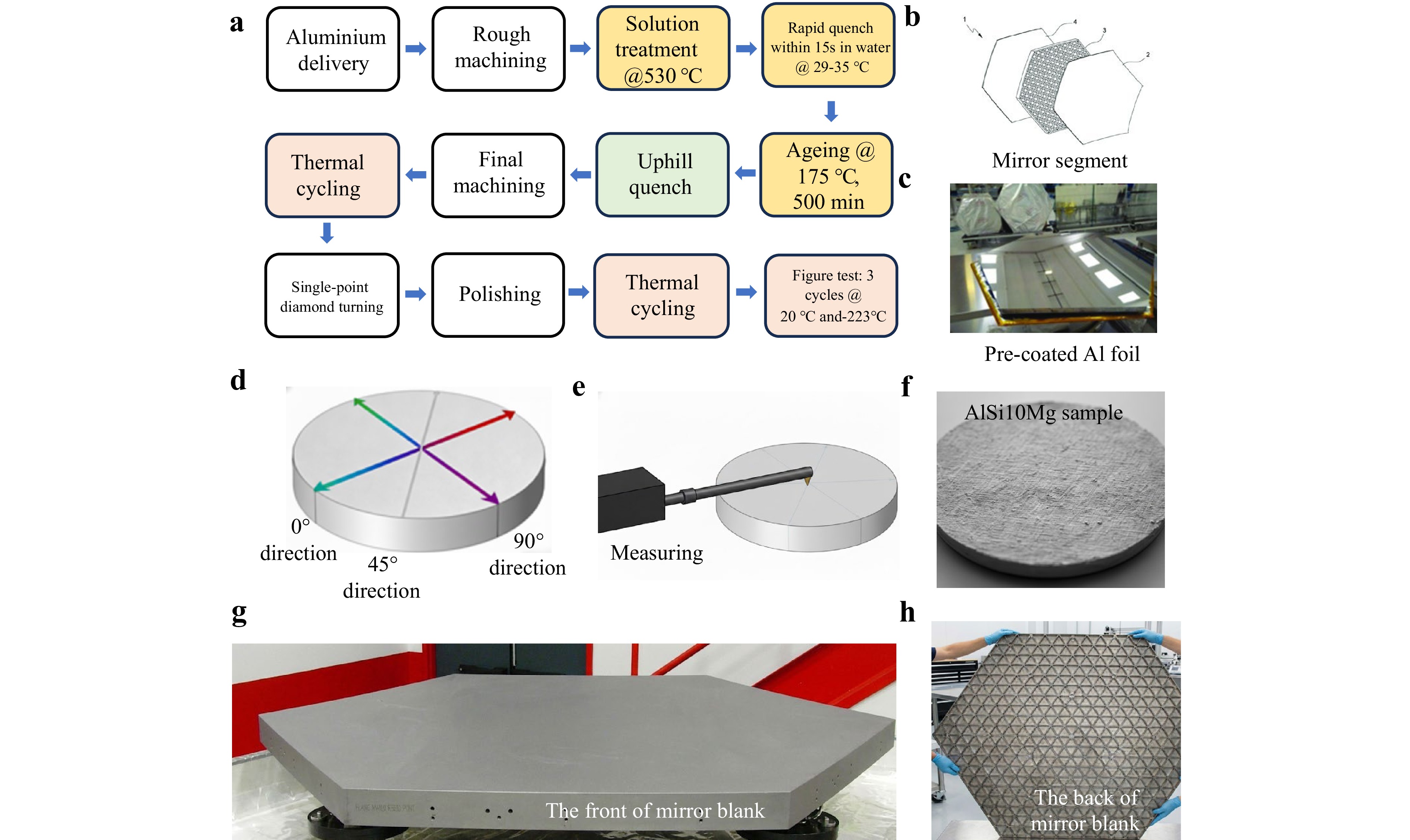
Fig. 3 a Manufacturing flow of the Ariel telescope mirrors based on Al 6061-T651. Reproduced with permission20. Copyright 2022, SPIE. b A detailed three-dimensional visualization of the mirror segment made possible by the innovative technique. Reproduced with permission21. Copyright 2021, SPIE. c Final replication on the pre-prepared panel of the reflecting pre-coated Al foil. Reproduced with permission21. Copyright 2021, SPIE. d CAD view of the prototype design with the three direction measurements. e CAD view of the profilometry machine working on the AlSi10Mg raw sample. f Picture of AlSi10Mg raw sample surface. g The front of an unpolished mirror blank, h The back of the mirror blank is precision-machined with this pattern.
New generations of telescope arrays, such as ASTRI and the Cherenkov Telescope Array Observatory (CTAO), will require the fabrication of thousands of square meters of reflective segments to construct the primary mirrors of the telescopes. Traditional low-cost manufacturing techniques include direct machining and polishing of glass slabs, diamond turning of pre-formed aluminum alloys sandwich panels, and replication of thin glass foils to create composite sandwich mirrors. G. Pareschi21 proposed an alternative solution based on the replication of aluminum alloys foils for the production of sandwich mirrors. This method simplifies the production process, allowing for the creation of low-cost panels made entirely of aluminum alloys. The process utilizes aluminum alloys foils pre-coated with a highly reflective and durable multilayer film, and involves a replication process using a mold with a convex curvilinear surface complementary to the optical shape of the mirror segment to be produced. As shown in Fig. 3b, c, the sandwich structure 1 comprises an optical reflecting foil layer 2, an intermediate layer made of foam material or an aluminum alloys honeycomb 3, and an aluminum alloys back plate 4 for thermo-structural purposes.
Compared to directly polished/diamond-turned glass or aluminum alloys panels, the replication method offers significant advantages in terms of production time and cost. Since the entire panel is made of the same metallic material (aluminum alloys) with high thermal conductivity, it can withstand large stresses and reduce the risk of deformation caused by bimetallic effects. Compared to glass/aluminum alloys composite panels, the all-metal panel is more robust and less prone to breakage22.
Melanie Roulet et al. conducted a systematic study on the application of additive manufacturing technology in fabricating lightweight X-ray lenses. The research team first designed a lens model with an arched structure using computer-aided design (CAD) software (Fig. 3d). For material selection, AlSi10Mg aluminum alloy was chosen as the printing feedstock, and the lenses were fabricated via selective laser sintering (SLS) technology following the 3D model (Fig. 3e). To optimize surface quality, the team implemented a systematic post-processing protocol, including three progressive steps: manual polishing, fine sanding, and sandblasting. Fourier transform analysis was employed to effectively eliminate surface waviness, allowing detailed characterization of surface roughness. Experimental results demonstrated that post-processed AlSi10Mg exhibited excellent surface quality, with sandblasting proving particularly effective in significantly reducing surface roughness, as shown in Fig. 3f. This study establishes a crucial technical foundation for the practical application of 3D-printed X-ray lenses. Similar additive manufacturing approaches can also be applied to Ti64 alloy23.
-
Beryllium has a low thermal expansion coefficient, high specific stiffness, low density, and high thermal diffusivity, making it an excellent material for astronomical mirrors. However, it is highly toxic, so strict protective measures are required during processing.
Liqiang Song and his colleagues16 have thoroughly explored the application of beryllium material in space astronomical instruments, especially as the substrate material for the tip-tilt mirror in the correlation tracker of the Space Solar Telescope (SST). The Hot Isostatic Pressing (HIP) technology was selected to fabricate the beryllium mirror substrate. HIP is a relatively new manufacturing method that compacts beryllium powder directly through hot isostatic pressing, which saves raw materials, reduces costs, and results in a densely structured product, enhancing the isotropy of beryllium material. Since beryllium is prone to oxidation when it comes into contact with abrasive materials and water, it is impractical to polish the bare surface of beryllium. Therefore, a dense plating layer is required to be formed on the beryllium mirror substrate. Nickel was chosen as the plating material because its coefficient of thermal expansion matches that of beryllium. After rough polishing and fine machining, the mirror surface is smooth enough for interferometer measurement. The final testing results of the beryllium mirror met the technical requirements for the tip-tilt mirror of the correlation tracker, proving that beryllium is an excellent reflective material for space astronomical instruments.
The 18-segment primary mirror of the James Webb Space Telescope (JWST) exemplifies how material selection and manufacturing processes serve specific scientific objectives (infrared observation) and extreme environmental conditions (deep-space cryogenic temperatures). The fundamental reason for its design as an infrared telescope lies in the fact that light emitted by many key celestial objects (such as early galaxies and planetary nurseries) predominantly exists in the infrared band due to cosmic redshift and dust obscuration. Meanwhile, components in Earth’s atmosphere, such as water vapor and carbon dioxide, strongly absorb most infrared light, making ground-based infrared observations extremely difficult. Consequently, JWST must operate in space.
JWST selected metallic beryllium (O-30 grade) over traditional glass-ceramics primarily for its thermal stability: when cooled from Earth’s ambient temperature to its operating temperature of approximately 40 K, beryllium’s microstructure fully releases internal stresses without phase transformation and is less prone to cracking than glass. This ensures that the mirror’s surface accuracy (achieving a final figure of 20 nm RMS) is maintained at cryogenic temperatures. The specific type of beryllium used in the Webb mirror is designated O-30, which is a fine powder. The powder is placed into a stainless-steel can and pressed into a flat mirror blank, as shown in Fig. 3g. To minimize launch mass, each blank is machined via back-milling into an ultra-thin “rib” structure only about 1 mm thick, achieving an exceptionally high stiffness-to-weight ratio. Although most of the metal is removed, the ribs are sufficient to maintain the segment’s shape stability, as shown in Fig. 3h. This results in an extremely lightweight segment, with each beryllium mirror segment weighing only 20 kg. Furthermore, to achieve high reflectivity in the infrared band, the mirror surfaces are coated with approximately 100 nm of pure gold (providing > 98% reflectivity in the infrared), protected by a thin layer of amorphous silicon dioxide.
Critically, all these manufacturing decisions stem directly from the fundamental requirements of an infrared telescope: According to blackbody radiation laws, any mirror surface at temperatures significantly above 40 K will emit substantial thermal radiation within the sensitive infrared band (1–29 μm), generating thermal noise that would swamp the faint astronomical signals. In fact, any object above absolute zero emits thermal energy. If the JWST’s optical system were too warm, its own infrared radiation—that is, thermal noise—would completely overwhelm the faint infrared signals from the cosmos, rendering observations impossible. Therefore, a combination of active cooling and passive sunshades, maintaining the entire optical system at around 40 K, is a prerequisite for ensuring its scientific performance. This stringent cooling requirement, in turn, dictates that its mirror material must possess exceptional dimensional stability under cryogenic conditions, which is the fundamental reason for selecting beryllium and employing specialized processes such as O-30 powder metallurgy and precision machining24.
-
Silicon Carbide (SiC) materials have an extremely low thermal expansion coefficient, high specific stiffness, low density, and high thermal diffusivity, making them ideal for astronomical mirrors. However, the manufacturing process for SiC is complex and costly, and the material is hard and challenging to polish, making large SiC mirrors difficult to produce. The Changchun Institute of Optics, Fine Mechanics and Physics (CIOMP) manufactured the world’s largest SiC aspheric mirror25. The fabrication of this ø4.03-meter aspheric mirror involved a multi-stage process to address critical challenges in materials science, manufacturing precision, and metrology, as illustrated in Fig. 4. Mirror blank preparation utilized innovative water-soluble room-temperature vanishing molds and gel casting to create a lightweight green body with complex semi-closed back structures. Reaction-bonding technology enabled the stitching of 12 segments into a monolithic blank, overcoming thermal mismatch and deformation risks through carbon-based binders and synchronized sintering. Fabrication combined CNC generating, stressed-lap grinding, and magnetorheological finishing (MRF) in a hybrid process chain, improving error convergence by 30% and achieving full-spatial-frequency error control (15.2 nm RMS surface figure error, 0.8 nm RMS roughness). To address SiC’s inherent porosity, a low-temperature PVD Si cladding (10–20 μm thick) was developed, minimizing thermal stress (< 50°C processing temperature) while ensuring high denseness and adhesion (thickness inhomogeneity < 5%). Metrology integrated swing-arm profilometry (SAP), CGH null interferometry, and phase deflectometry with turbulence-decoupling algorithms, achieving sub-6 nm RMS testing accuracy under controlled thermal environments (21.8–22.2°C ± 0.2°C). Gravity unloading systems with hydrostatic actuators counteracted self-weight deflection (6.1 nm RMS post-installation error), simulating zero-gravity conditions for space applications. Challenges like “print-through” effects in lightweight structures were mitigated via finite element analysis (FEA) and optimized tool paths. The final mirror, with an aerial density < 120 kg m−2 and ASR of 3.77 ppb, represents a leap in large-optics manufacturing, enabling advanced ground and space-based telescopes.
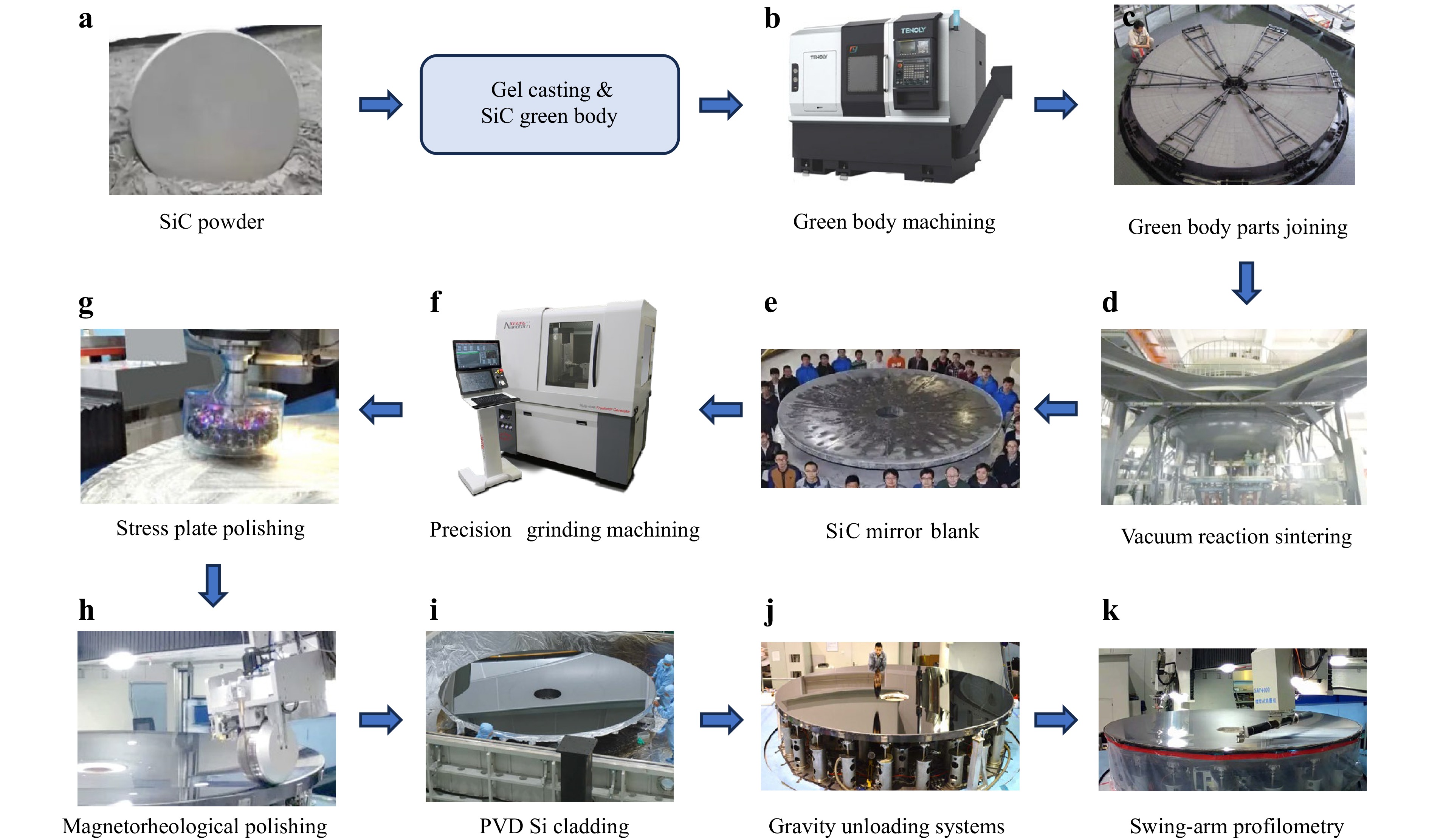
Fig. 4 Flowchart of SiC astronomical mirror manufacturing process. a SiC Powder. b Green body machining. c Green body parts joining. Reproduced with permission25. Copyright 2022, Springer Nature. d Vacuum reaction sintering. e SiC mirror blank. f Precision grinding machining. g Stress plate polishing. Reproduced with permission25. Copyright 2022, Springer Nature. h Magnetorheological polishing. i PVD Si cladding. Reproduced with permission25. Copyright 2022, Springer Nature. j Gravity unloading systems. Reproduced with permission25. Copyright 2022, Springer Nature. k Swing-arm profilometry. Reproduced with permission25. Copyright 2022, Springer Nature.
Xiaotian Shen and colleagues26 explored the topological optimization design of a double-sided SiC space mirror based on additive manufacturing technology (AM). They targeted the integrated design of the primary mirror (PM) and the fourth mirror (QM) in the Four-Mirror Anastigmatic (FMA) system to achieve a space telescope with low mass and compact structure. SiC was chosen as the mirror material for its high stiffness and thermal conductivity. A simplified prototype of the double-sided SiC mirror was manufactured and tested, proving the feasibility of producing a double-sided mirror with excellent surface quality through additive manufacturing technology. The surface figure accuracy of the prototype reached λ/50. One side of the mirror is spherical, while the other is flat to facilitate polishing and testing. A thick modified layer was then deposited on the SiC mirror surface and polished to achieve the final shape, followed by an Ag coating. The research results indicate that a lightweight, high-stiffness, and low-surface-error mirror structure was achieved through topological optimization, providing new ideas and methods for the design and manufacture of space telescope mirrors.
-
S. Utsunomiya and colleagues27 utilized an improved replication technique to fabricate ultra-lightweight CFRP (Carbon Fiber Reinforced Plastics) mirrors for space telescopes. By meticulously studying the replication technology and process conditions, they enhanced the replication method, which not only eliminated the fiber print-through on the CFRP surface but also achieved high shape accuracy for the mirrors. Currently, a shape accuracy of 0.6 µm and a surface roughness of 3 nm have been attained.
The diagrammatic illustration of the replication process is shown in Fig. 5a. Molds are made from materials with excellent machinability, such as Super Invar plated with Ni-P, which have been specially adjusted to have a thermal expansion coefficient close to that of CFRP. The CFRP parts are cured at 130°C for 2 hours, taking care to prevent shape distortion due to mismatched thermal expansion with the mold. After demolding the CFRP parts from the mold, necessary post-processing is carried out, such as removing the release agent marks. Optical grade epoxy resin is selected as the replication material, which can achieve a high surface smoothness after curing. Before replication, the resin undergoes vacuum degassing to remove internal bubbles and impurities. The degassed resin is evenly coated onto the surface of the CFRP mold. The CFRP part is then bonded to the resin-coated mold surface, ensuring no air bubbles are trapped. Curing is performed under vacuum at room temperature to further remove residual gases or air. Appropriate pressure is applied during the curing process to ensure the resin can fill the unevenness of the CFRP surface. After curing is complete, the CFRP part is removed from the mold and post-cured to ensure the final curing of the resin. Finally, the ultra-lightweight CFRP mirrors are finished and assembled. Fig. 5b displays the surface roughness profile of the as-molded CFRP, while Fig. 5c presents the post-replica measurement. The evaluation length for both scans was set at 400 μm. Notably, the height scale differs by an order of magnitude between the two plots, with the replica process reducing roughness to one-tenth of the original value. Additionally, Fig. 5d illustrates a CFRP parabolic mirror with a diameter of φ200 mm, fabricated using an ultra-high-precision machined Super Invar mold.
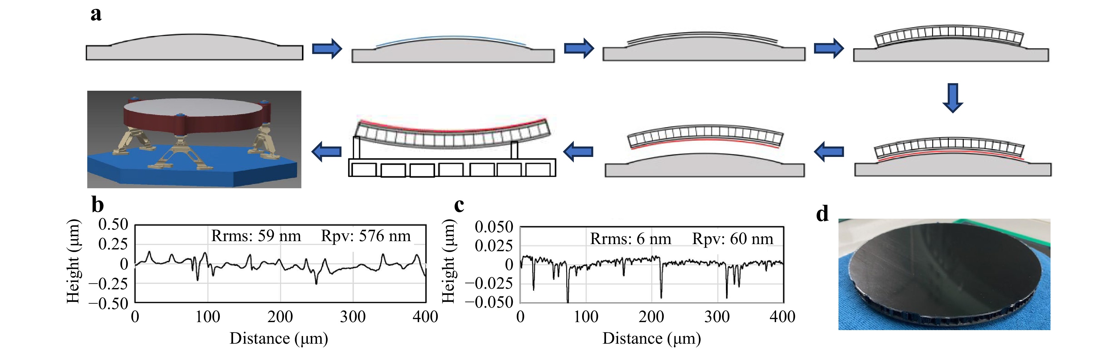
Fig. 5 a Diagrammatic illustration of the replication process. b Surface roughness curve of the CFRP as molded. c Surface roughness curve of the CFRP after replica. d Replicated ɸ200 mm reflector. Reproduced with permission27. Copyright 2022, SPIE.
-
Mirrors are a subset of optical components essential for the success of current and future space missions. Most of the astronomical telescopes ranging from earth observation to astrophysics and covering the whole electromagnetic spectrum from x-rays to far-infrared are based on reflective optical mirrors. These telescopes rely on mirrors to effectively collect and focus light from distant celestial objects. With the expansion of space missions to low Earth orbit, interplanetary trajectories, and deep space exploration, mirrors must operate in increasingly harsh environments, including extreme temperature fluctuations, cosmic radiation, micrometeoroid impacts, and the vacuum of space. In order to meet the needs of the astronomical telescope’s wide spectral bandwidth, large size, high resolution and long-term stability, the mirror material, coating and preparation process must be optimized to ensure the effective operation of the astronomical telescope at different wavelengths and environmental conditions.
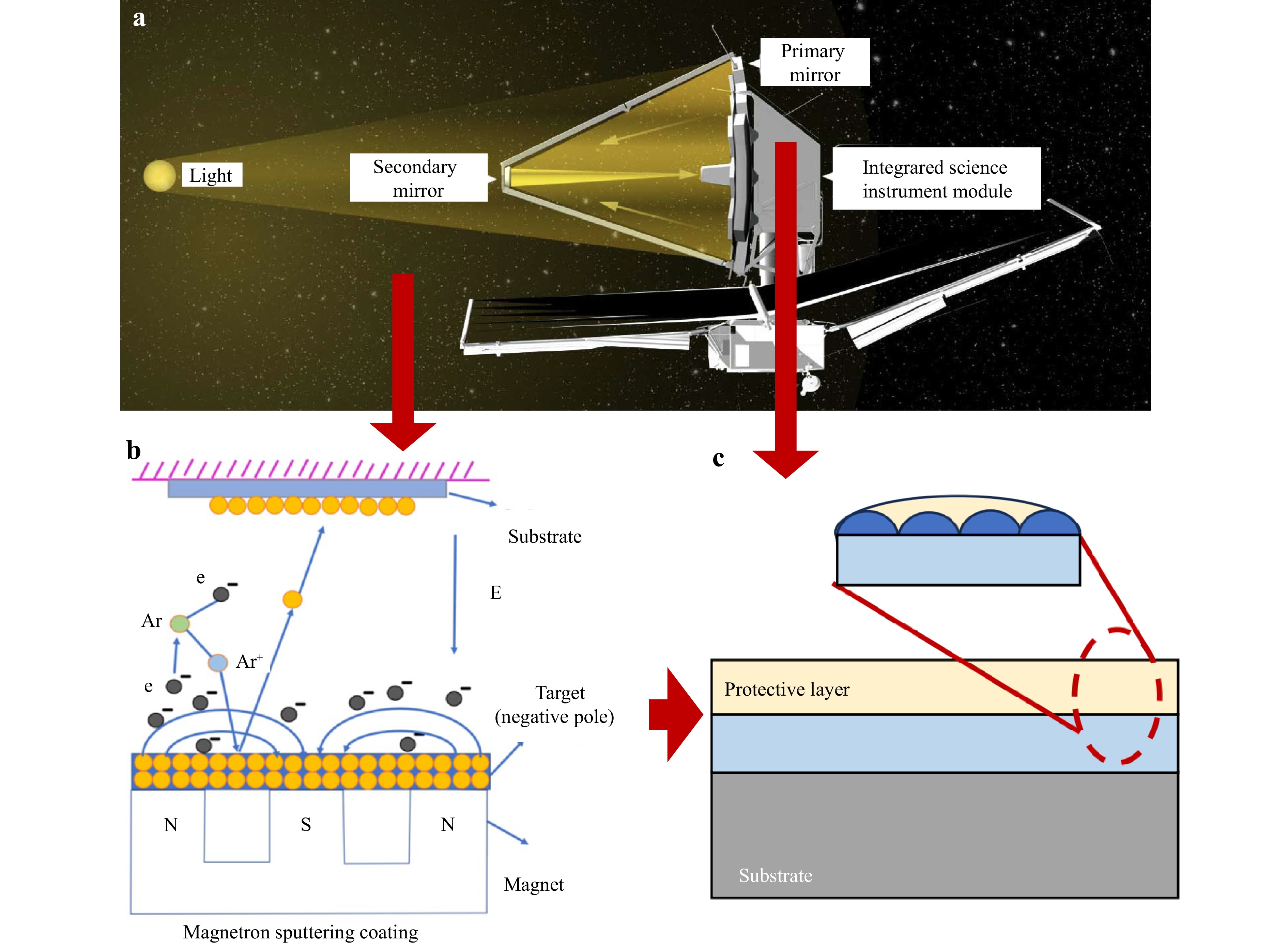
The development of infrared (IR) mirrors has been driven by the need for space telescopes to observe celestial objects emitting in the infrared spectrum, such as cooler stars, nebulae, and distant galaxies. Initially, infrared observations were limited to ground-based telescopes, but atmospheric interference, such as water vapor, significantly hindered observations in the infrared range. This led to the development of space-based infrared telescopes, beginning in the 1960s. The first major breakthrough came with the launch of the IRAS (Infrared Astronomical Satellite) in 1983, which observed the sky in the infrared range28. This was followed by ISO29 (Infrared Space Observatory) in 1995 and the Spitzer Space Telescope in 200330 , which enabled more detailed and longer observations. These telescopes required high-performance mirrors that could efficiently reflect infrared light without thermal emission interference, which led to advancements in materials and coatings for infrared mirrors. The main challenge for infrared mirrors is their ability to withstand extreme temperatures and reflect infrared light effectively. Traditional materials like aluminum alloys have been widely used due to their excellent reflectivity in the infrared range, but they are prone to oxidation, especially in space environments. As a result, silver coatings, known for their superior reflectivity, have been used, though they require protective coatings to prevent oxidation. Other coatings, such as silicon monoxide (SiO) or silicon carbide (SiC), are used for better thermal and mechanical stability (as shown in Fig. 6). The James Webb Space Telescope (JWST), launched in 202131, exemplifies modern advancements in infrared mirrors, employing gold-coated beryllium mirrors designed for high thermal stability and low weight in the extreme cold of space. Current research focuses on adaptive optics to correct for distortions caused by atmospheric conditions or thermal effects in infrared telescopes. New materials like graphene and carbon nanotubes are being explored for their ability to provide stable, lightweight, and high-reflectivity coatings. Furthermore, innovations in cryogenic performance are essential, as infrared telescopes operate at cryogenic temperatures, requiring coatings and materials that remain stable and effective under such conditions.
The development of ultraviolet (UV) mirrors has been crucial for the study of high-energy processes in the universe, such as the behavior of stars, black holes, and quasars. Unlike infrared light, UV radiation is absorbed by Earth’s atmosphere, making space-based telescopes necessary for UV observations. The first major UV telescope, the Hubble Space Telescope (HST), launched in 1990, marked a significant milestone in the study of the UV spectrum. HST’s mirrors were designed to optimize UV observations and have remained one of the most important tools for studying UV radiation. UV mirrors need to efficiently reflect high-energy ultraviolet light while maintaining structural integrity in space environments. Historically, aluminum alloys was used for UV mirrors, but it was found to be insufficient for the highest-energy UV wavelengths. To overcome this, magnesium fluoride (MgF2) and silicon carbide (SiC) coatings have been used as they offer better reflectivity in the UV range and greater resistance to space weathering32,33. One area of intense research is the development of multi-layer coatings that enhance UV reflectivity by utilizing the interference effect in thin-film technology. This is crucial for optimizing mirrors for specific UV wavelengths. Fig. 7 shows the structure of the multilayer and the reflectance curves of the single and multilayers. UV mirrors are also vulnerable to degradation from ionizing radiation in space, leading to efforts to develop more robust materials that can withstand these harsh conditions for longer periods. In addition, aluminum-based coatings with overcoats of magnesium fluoride (MgF2) or silicon dioxide (SiO2) are being developed to improve durability and maintain reflectivity over long missions. Ongoing studies focus on advancing optical coatings and exploring new materials to ensure long-lasting durability and performance in the harsh UV space environment.
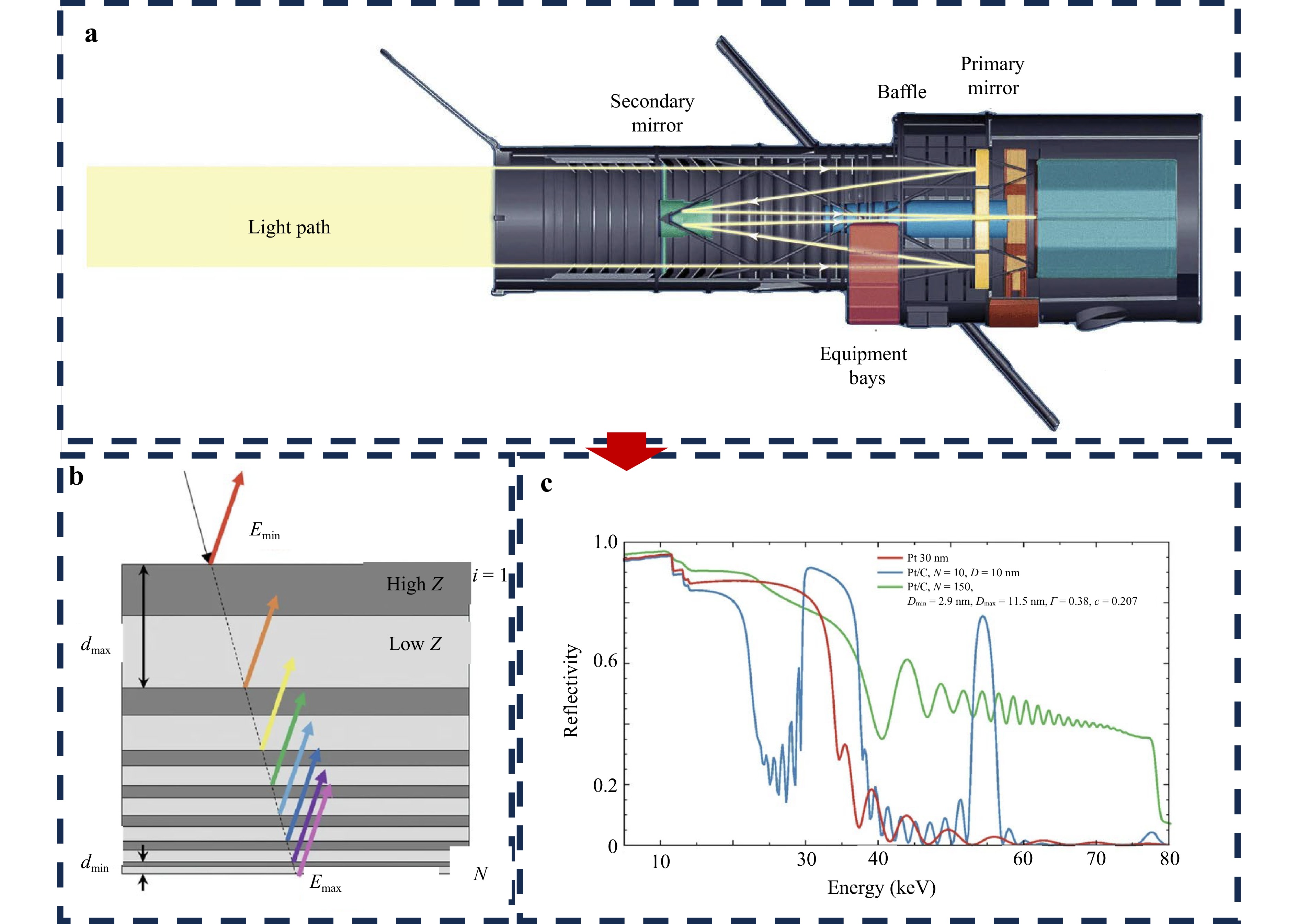
Fig. 7 a Ultraviolet Telescope structure b Cartoon of the power-law graded multilayer stack. c multilayer performance at a fixed incidence angle of 2.5 mrad for (1) a single-layer (red), (2) a N = 10 bi-layer constant thickness stack (blue), and (3) a power-law depth-graded multilayer stack (green)32,33
X-ray astronomy was long hindered by the fact that X-rays do not pass through Earth’s atmosphere, requiring the development of space-based observatories. The early attempts at X-ray observations, such as the Uhuru satellite launched in 197034, used direct detection techniques, but these did not rely on reflective optics. The breakthrough in X-ray mirror development came with the Chandra X-ray Observatory, launched in 199935, which used the principle of grazing incidence to effectively reflect X-rays. Unlike visible and infrared light, X-rays have much higher energy and cannot be reflected at normal incidence angles. As a result, X-ray mirrors use a technique called grazing incidence, where X-rays are reflected at very shallow angles, often less than 10 degrees. Early X-ray mirrors used thin gold or platinum coatings on glassy substrates or ceramic materials. The most significant challenge for X-ray mirrors is achieving extremely high precision in curvature and surface finish, as even minute deviations can degrade performance. The structural design of the X-ray telescope is shown in Fig. 8, mirrors for X-ray telescopes are typically constructed using multi-layer coatings that optimize reflectivity for specific X-ray wavelengths. Current research in X-ray mirror technology focuses on micro-fabrication and precision manufacturing to improve the surface finish and precision of the mirrors. Advances in multi-layer coatings, such as tungsten-based layers, are being explored for higher reflectivity at specific X-ray wavelengths. Moreover, thermal stability remains a priority, as X-ray telescopes operate in deep space where temperature variations can be extreme. Research into more thermally stable coatings is ongoing to ensure mirrors can maintain their performance across vast temperature ranges.
Each of these fields continues to progress with new innovations in materials, coatings, and manufacturing techniques, ensuring that mirrors for infrared, ultraviolet, and X-ray astronomy will meet the growing demands of space-based telescopes and the future of astrophysical exploration. To provide a more straightforward display of the characteristics of various coating materials, we have prepared a Table 2 summarizing typical coating materials and their applications:
Material Type Spectral Range (μm) Avg. Reflectance (%) Thermal Stability Key Applications Al+MgF2/LiF 0.1-0.3 88-90 Good (200°C) • FUSE,
• GALEXAg+NiCrNₓ 0.5-2.5 >95 Improved (150°C) • JWST secondary Au 0.7-30 >98 Excellent (cryo) • JWST primary SiC 0.02-6 70-97 Outstanding (>500°C) • EUV telescopes Mo/Si 0.013-0.05 ~40 Good (300°C) • EUVE Table 2. Comparison of modern optical coating materials and their performance
-
As the fundamental basis for manufacturing ultra-precision mirrors in large astronomical telescopes, elucidating material removal mechanisms directly determines the low-frequency error control capability and subsurface defect suppression level in optical surfaces. Zhao et al.36 demonstrated ultra-precision grinding technology for silicon-based mirror processing, achieving 56% reduction in subsurface damage depth and surface figure accuracy improvement to λ/50 (λ = 632.8 nm) through parameter optimization, dwell time algorithm refinement, and laser/ultrasonic-assisted strategies. Laser-assisted grinding exhibits unique advantages: For telescope-specific low-thermal-expansion materials, Gu et al.37 revealed that laser-induced thermal gradient fields promote dislocation recombination (39% microstrain reduction) and subsurface phase transformation in silicon carbide, significantly enhancing optical scattering characteristics. Focusing on telescope mirror-grade silicon carbide, Zhou et al.38 established a dynamic removal model adapting multi-axis machining characteristics (contact elastic deformation-ductile regime removal-brittle domain suppression-residual stress relaxation), while Liu et al.39 discovered feed rate regulation of subsurface crack propagation paths (45° spiral trajectory → radial layering transition), enabling 70% efficiency improvement in large-aperture mirror processing while maintaining PV value better than λ/20. In ultrasonic-assisted polishing, Dai et al.40 correlated vibration parameters with removal characteristics, finding 3-4 μm amplitude achieves synergistic optimization of nanoscale roughness (Ra < 0.8 nm) and subsurface lattice integrity. For telescope borosilicate glass, Wang et al.41 developed a quantitative model linking abrasive size to subsurface microcrack depth, guiding full-band error control < 15 nm RMS in φ2 m mirrors, while Li et al.42 proposed a thermo-mechanical coupled dynamic fracture toughness model explaining micro-removal behavior under extreme thermal environments (±50℃ variations), providing theoretical basis for giant telescope thermal stability control.
Yin et al. investigated the grinding process of SiCp/Al composites by diamond abrasive grains through finite element simulation. The study revealed that the aluminum matrix primarily undergoes plastic deformation, while SiC particles experience crack initiation, propagation, and eventual fracture. The simulation demonstrated that chip thickness is a critical factor determining machining quality, as it governs whether SiC particles are removed via plastic deformation or brittle fracture43. The Li research team further employed molecular dynamics simulations to show that at the nanoscale, dislocation motion in the aluminum matrix dominates the initial plastic deformation, whereas brittle fracture of SiC particles occurs under higher loading conditions44. For fiber-reinforced SiC/SiC ceramics, Prinz et al. developed a FEM-SPH coupled model to simulate the single-grit cutting process of silicon carbide fiber-reinforced ceramics (SiC/SiC), analyzing the effects of grit geometry, fiber orientation, and cutting depth on material removal behavior. The results showed that fiber orientation significantly influences material removal mechanisms: longitudinal grinding leads to fiber fracture and interfacial debonding, transverse grinding is dominated by brittle fracture, while normal grinding causes fiber pullout45. This study provides a theoretical basis for optimizing precision machining of ceramic materials. These simulation results were validated using micro-CT and white light interferometry, offering theoretical guidance for optimizing real-world machining parameters.
-
Astronomical telescopes have high requirements for the surface shape accuracy and surface roughness of the mirrors, which usually need to reach the accuracy of sub-micron level or even nanometer level. Any shape errors in any frequency band of the mirror surface will negatively affect the imaging quality, resulting in a decrease in the resolution and reflection efficiency of the optical system46. Ultra-precision turning can create highly precise optical surfaces, minimizing form errors and achieving surface roughness within acceptable limits for high-performance optical systems26,47,48. Therefore, ultra-precision turning has become an important means of manufacturing these high-precision astronomical telescopes. This section mainly summarizes some developments in the field of high-quality machining of astronomical telescopes, such as error analysis of ultra-precision, ultra precision turning capability, and ultra precision turning quality. Curved microstructure, named reflective mirror can be shaped well by ultra-precision engineering. To promise and enhance its optical performance, the full-bandwidth shape accuracy control from the macroscopic to the microscopic scale (from microns to sub-nanometers) needs to be achieved46. Besides, to machine ultra-precision optical components with large apertures, manufacturers both at home and abroad have developed corresponding large aperture vertical ultra-precision machining equipment. This equipment enables precise motion control over a wide range, as shown in Fig. 9.
-
Ultra precision machining errors include geometric errors, clamping errors, thermal errors, etc. The geometric error mainly stems from the relative motion of the tool and the workpiece, while the clamping error relates to how the workpiece remains stable during machining.
A three-axis ultra-precision lathe has two translational axes and one rotational axis, i.e., X-, Z- and C-axes, respectively. Xianli Liu et al.49 established a geometric error model for a three-axis ultra-precision lathe using multi-body system theory to analyze how geometric errors affect coordinate distortion and form accuracy. Machining errors were categorized into five types based on the direction of coordinate distortion: X, Y, radial, circumferential, and axial. These categories impact different surface types, and the main errors affecting form accuracy were identified. Simulations confirmed the influence of these errors, and machining a plane-spherical surface helped isolate and compensate for them. This led to a significant improvement in the form accuracy of a freeform surface.
In addition, the clamping error of large-sized astronomical telescopes can also affect the quality of ultra precision turning machining. The source of clamping errors may include the manufacturing tolerance of the fixture, the deformation of the workpiece during clamping, and even the insufficient rigidity of the machining machine. Cyril Bourgenot et al.26 used finite element analysis to reduce fixture weight and improve stiffness, minimizing deformation from rotational and cutting forces that affect optical performance. The FEA results are presented in Fig. 10, showcasing the deformation along the axis corresponding to the optical axis. With a cutting force of 10 N in Fig. 10a, the deformation measures approximately 3.9 μm PV. Fig. 10b illustrates the displacement outcome caused by rotational forces of 400 RPM, again along the spindle axis.
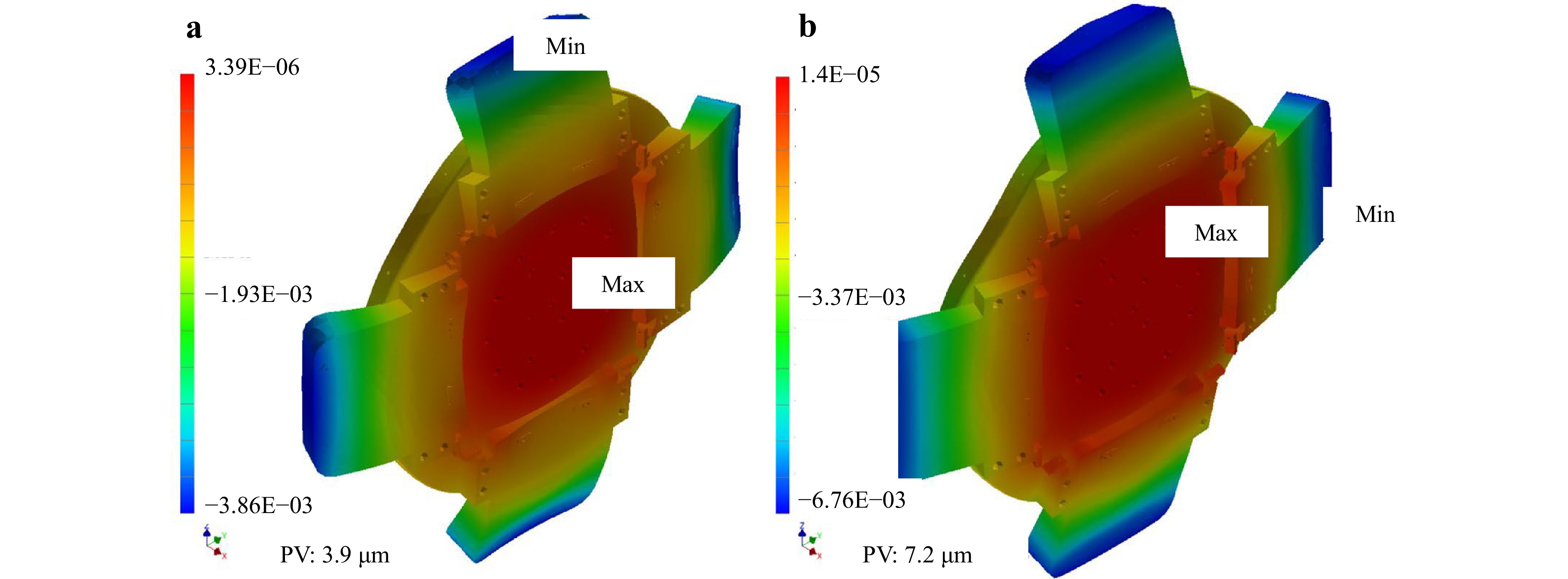
Fig. 10 a Displacement modeled for a cutting force equal to 10 N b and a rotational force induced by a rotation speed of 400 RPM (7 rev s−1). Reproduced with permission26. Copyright 2024, MDPI.
In order to reduce tool contour error in ultra-precision diamond turning, Kodai Nagayama et al.50 used white light interferometry for measurement and compensation. The white light interferometer provides high-precision, real-time measurement of the diamond tool contour before machining. Based on these measurements, the tool path is adjusted to compensate for any contour deviations. This method significantly reduces form errors during the machining of freeform surfaces. Ho-Sang Kim et al.51 used a special chucking device to mount the mirror substrate on the spindle with a required large offset to the axis of rotation, which has been specially designed to minimize elastic deformation caused by centrifugal inertia and clamping force.
-
The performance of astronomical telescope mirrors depends not only on the geometric accuracy of the surface during machining, but also on the characteristics of the material itself and its performance under extreme conditions. Therefore, the optical performance of astronomical telescopes also needs to be considered to ensure their long-term stable operation in the space environment. These intrinsic properties include thermal stability, resistance to deformation, and dimensional stability under extreme temperature and vacuum conditions. The effective control of these factors not only helps to reduce the geometric deviation introduced by machining errors but also ensures that the mirror maintains its optical performance under different service conditions. Especially in astronomical observations, telescopes often need to work in extreme temperature differences, and any small deformation or thermal expansion of materials can lead to a significant decline in optical performance. Therefore, in the manufacturing process, these characteristics of the material must be taken into account, and through accurate processing and regulation, to ensure its stability and durability under extreme conditions.
The mirror surface obtained by traditional ultra precision turning processing will exhibit serious diffraction phenomena when applied to the visible light band. The diffraction phenomenon is that there are several high-order diffraction spots distributed horizontally and vertically around the central bright spot on the receiving screen. For the case of polychromatic light, the diffraction phenomenon is the rainbow pattern around the fluorescent lamp image formed by mirror reflection. The diffraction phenomenon causes a decrease in the reflectivity and imaging quality of the mirror, affecting the optical performance of the mirror. Diffraction phenomenon is an optical phenomenon in which some reflected light does not follow the law of reflection when the surface roughness of ultra precision turning is on the same order of magnitude as the incident light wavelength. For diffuse reflection caused by larger surface roughness, the reflectivity and imaging quality are lower. Therefore, surface roughness is a key factor in determining whether diffraction effects occur on ultra precision turning surfaces52. Experiments have shown that the distribution of diffraction spots on ultra precision turning surfaces is closely related to their three-dimensional surface morphology53. Tomov et al.54 studied various factors that affect the surface quality of turning machining, and classified the factors that affect roughness, waviness, and surface shape accuracy based on the spatial wavelength corresponding to surface errors.
Achieving high-precision profiles and sub-nanometer surface roughness requires a coordinated multi-step process, with ultra-precision turning playing a pivotal role. Utilizing single-point diamond turning, this step establishes an initial high-precision surface shape and low roughness, providing a foundational baseline for subsequent polishing. Advanced techniques such as magnetorheological polishing55 and ion beam polishing56 are then employed to refine residual mid- and high-spatial frequency roughness, ensuring optimal surface quality and optical performance57,58. This multi-stage process effectively combines shape accuracy with minimized surface scatter and reflection losses, serving as the cornerstone for manufacturing high-performance optical components59.
-
The brittle-to-ductile transition (BDT) plays a pivotal role in achieving ultra-precision machining of hard-brittle materials used in astronomical optics, where sub-nanometer surface integrity is critical to minimize optical distortion60–62 (Fig. 11). For large-aperture telescope components, the BDT threshold must be precisely controlled to balance removal efficiency and subsurface damage. As summarized in Table 3, different mirror materials exhibit distinct BDT characteristics and processing requirements. Gu et al.63 demonstrated that magnesium aluminum spinel (a candidate material for lightweight space telescope mirrors) exhibits a critical scratch depth of 12.7 nm below which plastic-dominated removal preserves surface roughness below λ/20 (visible spectrum). In SiC grinding for space telescope primary mirrors, Liu et al.39 established a three-stage transition mechanism (plastic → plastic-brittle coexistence → brittle) with critical cutting depth thresholds matching the Rayleigh criterion for mid-infrared wavelengths. Zhou et al38 applied their finite element model to optimize grinding parameters (grit radius = 1.25 µm, velocity = 80 m s−1) specifically for meter-class SiC mirror blanks, achieving sub-surface crack depths < 50 nm to meet NASA’s LISA mission requirements. Chen et al.64 proposed electrochemical jet oxidation as a pre-treatment for segmented SiC mirror assemblies, enabling ductile-mode grinding with 40% reduced depth while maintaining λ/40 surface figure accuracy. For ultra-low expansion glass ceramics, Pratap et al.65 defined dual critical thresholds (plastic→15.72 nm, brittle→29.80 nm) that correlate with residual stress-induced birefringence in laser interferometer applications. Gu et al.66 developed a four-stage BDT classification (brittle/semi-brittle/semi-ductile/ductile) tailored to aspheric lens grinding, providing a process window for achieving < 1 nm RMS surface errors on BK7 glass corrector plates.
Material Application Critical Depth (nm) Achievable Roughness Key Challenges MgAl2O4 Spinel Lightweight space mirrors 12.7 < λ/20 (visible) Limited material availability SiC Space telescope primaries 15-25 (three-stage transition) < 50 nm SSD Medium-frequency error control ULE Glass Monolithic large mirrors 15.72 (plastic) / 29.80 (brittle) < 1 nm RMS Stress-induced birefringence BK7 Glass Corrector plates 8-15 (four-stage BDT) < 1 nm RMS Tool wear management Table 3. BDT parameters and grinding performance for astronomical mirror materials
-
Research on precision control in grinding machining is a critical focus in practical manufacturing. Current studies primarily concentrate on three key aspects: In terms of behavioral error control, Yu et al.67 pioneered a multi-source coupling model for aspheric grinding of telescope primary mirrors, incorporating wheel arc profile errors, radius measurement errors, and wear, thereby improving contour accuracy to 2 μm. Yao’s team67 advanced this field by proposing a high-order curve fitting method combined with real-time wheel profile compensation for normal residual errors, reducing form accuracy from 13.7 μm to 1.22 μm in aspheric cylindrical lens arrays. Gu et al.68 established time-dependent wear prediction models for continuous polishing of 8 m-class segmented mirrors, while Shui’s team69 implemented gravitational deformation compensation through finite-element assisted digital twin systems. Nasr et al.70 optimized slow tool servo parameters to minimize turning marks in off-axis parabolic segments using machine learning. For surface roughness control, Yao et al.67 demonstrated sub-nanometer Ra surfaces through spiral toolpath optimization with dwell-time control (Fig. 11a), a finding later extended to complex surfaces by subsequent research69. Lube et al.71 quantified subsurface damage (SSD) thresholds critical for mirror laser-induced damage resistance, establishing grinding-etching synergy protocols for Zerodur materials, whereas Nasr’s team70 reduced surface waviness errors by 40% through parameter optimization (Fig. 12b-d). Regarding material removal characteristics, Yu et al.72 formulated pressuredependent removal functions for stressed lap polishing systems. Yao’s team67 implemented real-time removal rate adjustment using in-situ interferometric measurement feedback, while Goel et al.73 improved material removal uniformity by 52% through multi-tool synergy strategies in segmented mirror processing. These advancements highlight the maturation of a complete technical chain from error to parameter synergy. However, challenges persist in cross-scale material removal mechanisms and real-time constraints of intelligent algorithms. Future efforts should prioritize: (1) hybrid models integrating physical principles with data-driven compensation, (2) cross-scale mapping of machining parameters to surface integrity and component performance, and (3) digital twin-enabled closed-loop systems to transcend micron-level compensation toward subsurface property regulation.
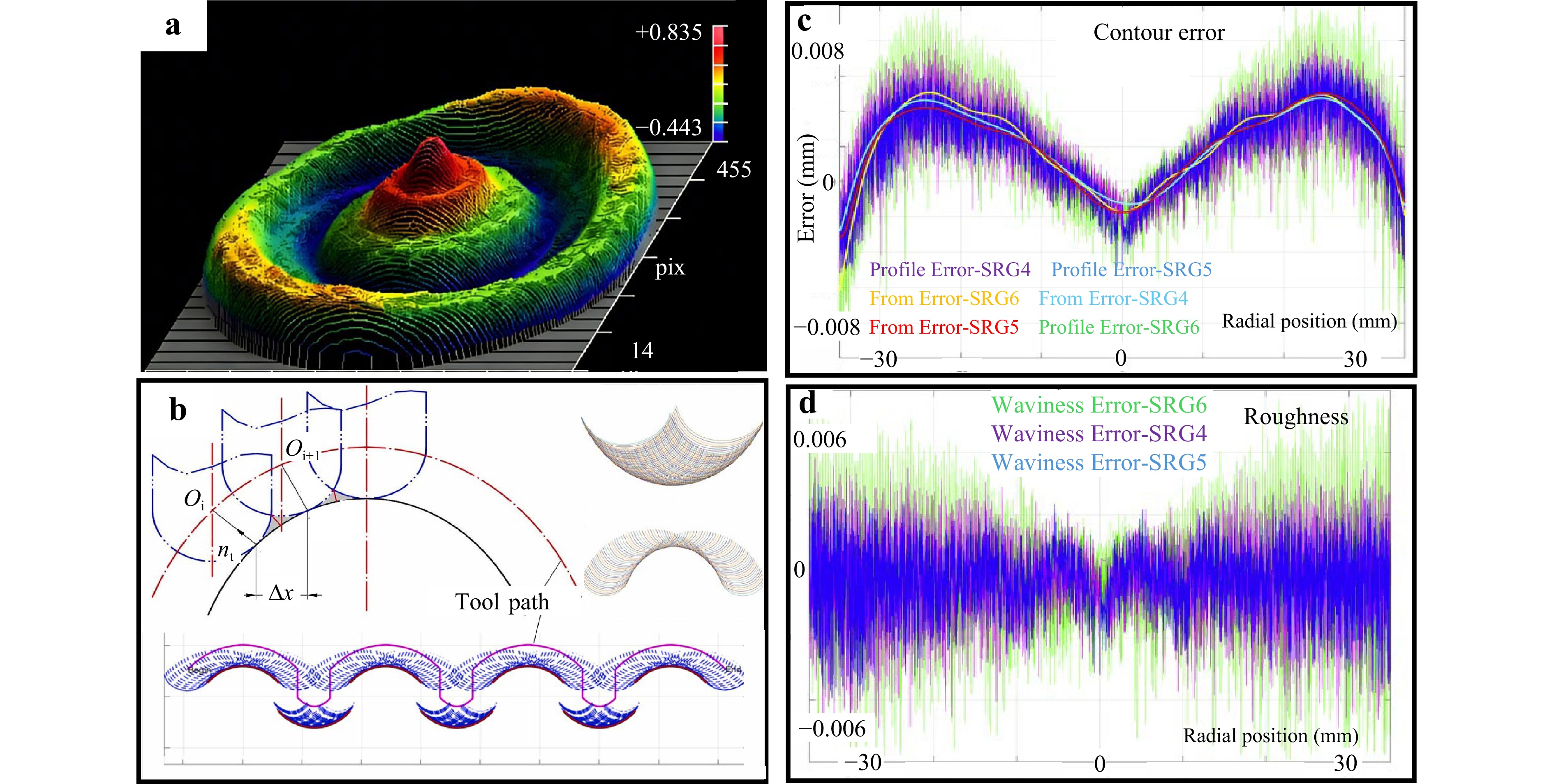
Fig. 12 Grinding accuracy control. a Workpiece modeling. Adapted with permission70. Copyright 2024, Elsevier. b Trajectory planning. Reproduced with permission67. Copyright 2023, Elsevier. c Contour error. Adapted with permission70. Copyright 2024, Elsevier. d Surface roughness. Adapted with permission70. Copyright 2024, Elsevier.
-
With the advancement of new technologies, numerous scholars have begun developing innovative machining techniques that demonstrate significant advantages in enhancing processing efficiency and material quality. The performance characteristics of the aforementioned advanced grinding methods are comparatively summarized in Table 4. Laser Ultrasonic Assisted Grinding (LUAG), a novel grinding method combining laser heating and ultrasonic vibration, significantly improves the surface hardness of AlN while reducing its friction-wear coefficient, surface roughness, and subsurface damage. It further optimizes the crystal structure of AlN, thereby enhancing its mechanical properties74. Electrochemical Jet Assisted Grinding (EJAG) effectively enhances the grinding efficiency and surface integrity of SiC by integrating electrochemical jet anodization with a soft grinding wheel. This approach lowers surface hardness, minimizes subsurface damage, and shortens machining time64. The biomimetic leaf vein-structured grinding wheel (VLSGW) optimizes aerodynamic characteristics, effectively reducing airflow recirculation and air pressure in the grinding zone. This results in decreased grinding forces, improved surface quality, and enhanced wear resistance, showcasing superior grinding performance75. Elliptical Ultrasonic Vibration Assisted Grinding (EUVAG) significantly reduces grinding forces and specific energy by altering the contact state and relative motion between abrasive grains and the workpiece. It achieves higher material removal rates and improved surface integrity, offering new insights for efficient precision grinding of hard-brittle materials76. These novel methods not only elevate grinding efficiency but also remarkably enhance workpiece surface quality and mechanical performance, opening up new development opportunities in precision machining.
Technology Removal Rate Surface Quality Applicable Materials Cost Efficiency Conventional Grinding Medium Moderate All ceramics High LUAG High Excellent AlN, SiC Medium EJAG Medium-High Very Good SiC, Composites Medium Biomimetic Wheel Medium Good Most brittle materials High Table 4. BDT parameters and grinding performance for astronomical mirror materials
-
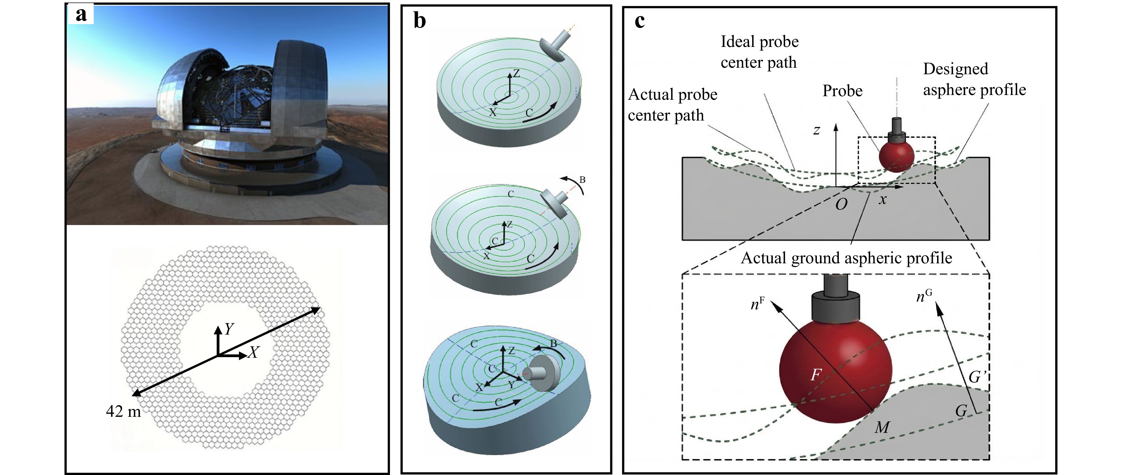
The primary mirror of the Thirty Meter Telescope (TMT) consists of 492 hexagonal segment mirrors3. The primary mirror of the European Extremely Large Telescope (E-ELT), with a diameter of 39 meters, is composed of 798 hexagonal segments, each measuring 1.4 meters. For telescopes requiring the fabrication of hundreds of sub-mirrors, the stressed-mirror polishing technology is commonly employed77,78. This process begins with rough shaping of the aspheric surface. Under applied stress, the aspherical surface is deformed into a spherical shape, facilitating grinding and polishing to achieve a sufficiently smooth surface. Once the stress is released, the mirror returns to its original aspheric shape. After the large-aperture mirror is manufactured, it is cut into the desired hexagonal segments and undergoes ion beam figuring to achieve the final high-precision surface. Cutting after polishing avoids the turned-down edge phenomenon, which is difficult to prevent during the polishing process.
These unique advantages make the stress mirror polishing technology (SMP) widely used in the manufacture of large-aperture telescopes. For the 492 hexagonal segment mirrors of the TMT primary mirror, the Nanjing Institute of Astronomical Optics & Technology (NIAOT) has developed a Stressed Mirror Continuous Polishing technique based on continuous polishing technology. This method can simultaneously polish more than three segments, significantly accelerating the mass production efficiency of off-axis segments79, as illustrated in Fig. 13. By developing a Linear Variable Differential Transformer (LVDT), large aspherical deviations are achieved. After stress release, a surface accuracy of 1.12 μm PV and 0.23 μm RMS is obtained on mirrors with 8-meter off-axis distances, providing an excellent starting point for subsequent Ion Beam Figuring80. The segment mirrors are expected to be replaced every two years after installation, for which a Segment Mirror Exchange Robot based on force control technology has been specially developed81.
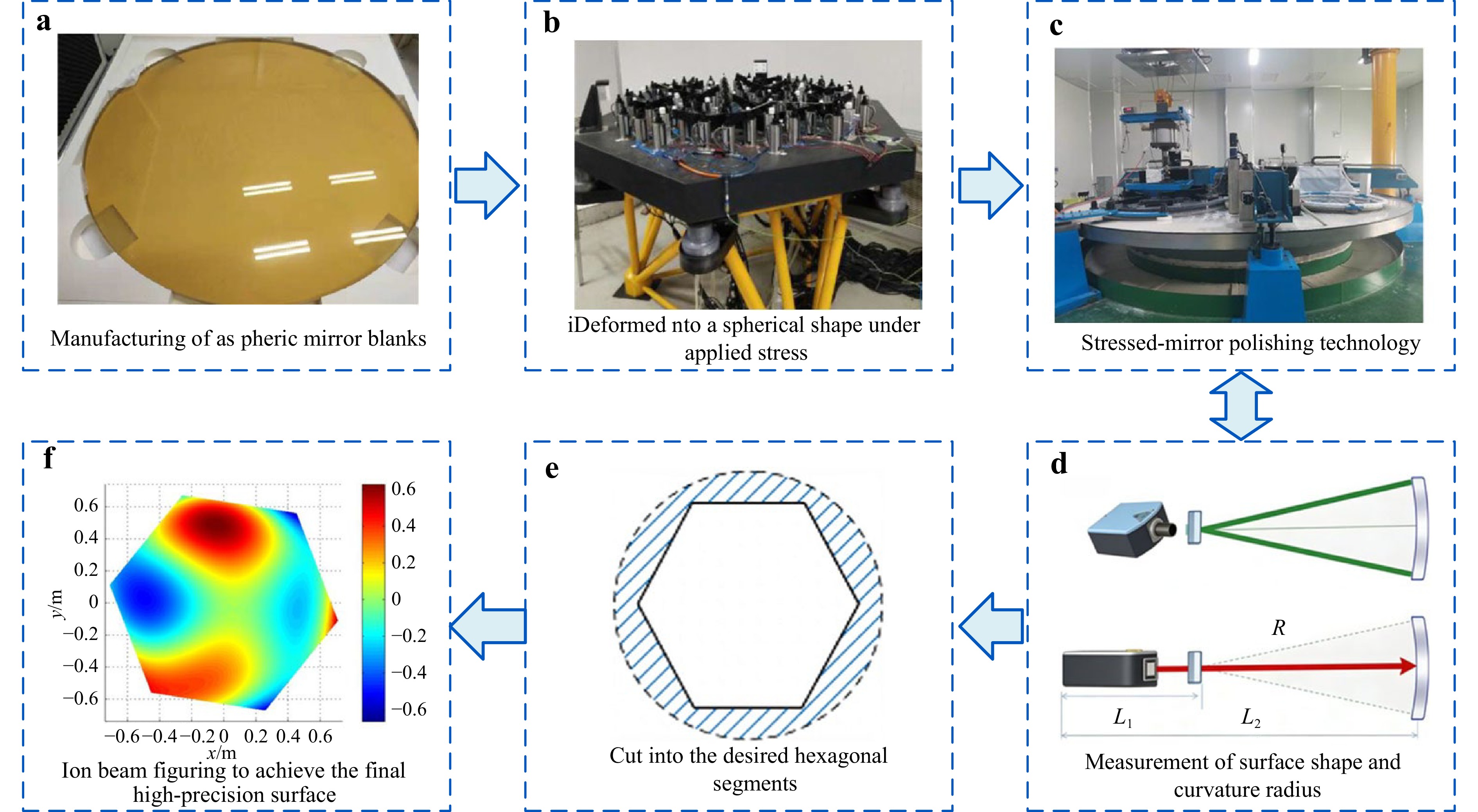
Fig. 13 Stressed Mirror Continuous Polishing Technique. a Manufacturing of aspheric mirror blanks. Reproduced with permission79. Copyright 2020, SPIE. b Deformed into aspherical shape under applied stress. Reproduced with permission79. Copyright 2020, SPIE. c Stressed-mirror polishing technology. Reproduced with permission79. Copyright 2020, SPIE. d Measurement of surface shape and curvature radius. Reproduced with permission79. Copyright 2020, SPIE. e Cut into the desired hexagonal segments. f Ion beam figuring to achieve the final high-precision surface. Reproduced with permission79. Copyright 2020, SPIE.
-
The E-ELT’s primary mirror consists of numerous large-aperture segmented mirrors. The large-scale production of these segments requires improvements in traditional manufacturing methods to minimize manual intervention and reduce processing time. D. Walker et al. developed a novel process chain distinct from stress mirror polishing to produce eight 1.4 m hexagonal segments82. Polishing and figuring are performed on pre-fabricated hexagonal blanks to reduce handling costs and potential damage during the polishing phase. Initially, the mirrors are shaped into hexagonal segments and off-axis aspheres using the Cranfield University BoXTM ultra-precision grinding machine, achieving a 1 μm RMS form error over areas larger than 1 meter. The grinding process induces subsurface damage up to 10 μm deep, which must be removed during subsequent polishing stages82.
To achieve this, bonnet polishing technology is employed. Bonnet polishing (BP) is a high-precision method specifically designed for aspheric and free-form mirrors. This technology was jointly developed by the University of London and Zeeko Company in the UK. The bonnet polishing tool consists of an inflatable flexible airbag with a spherical crown and a polishing die, such as a polyurethane polishing pad or cloth, attached to it. The airbag’s elasticity after inflation allows it to automatically adapt to the curved surface of the workpiece, enabling the same airbag to polish surfaces with different curvatures. This method is suitable for rotating aspheric and free-form surfaces and offers high flexibility and material removal rates.
The Zeeko IRP1600 CNC polishing machine is used for polishing the segmented mirror. Recirculated cerium oxide slurry is employed for polishing, form correction, and smoothing of the mirror segments. The process utilizes a raster polishing path and bonnet-shaped tools, with different bonnet sizes selected for various stages of processing. When polishing the mirror edges, the tool is lifted, contact pressure is reduced, and compensation is made for the decreased contact area83. To better integrate polishing and measurement iterations, OpTIC-Glyndŵr has integrated the Zeeko IRP1600 CNC polishing machine with a 10-meter high test tower84, as shown in Fig. 14. Through stringent environmental monitoring and control, in-situ testing is enabled at the manufacturing site82. A linear profilometer and a high-resolution on-machine stitching interferometer are used for local inspection of the mirror’s shape profile and edges.
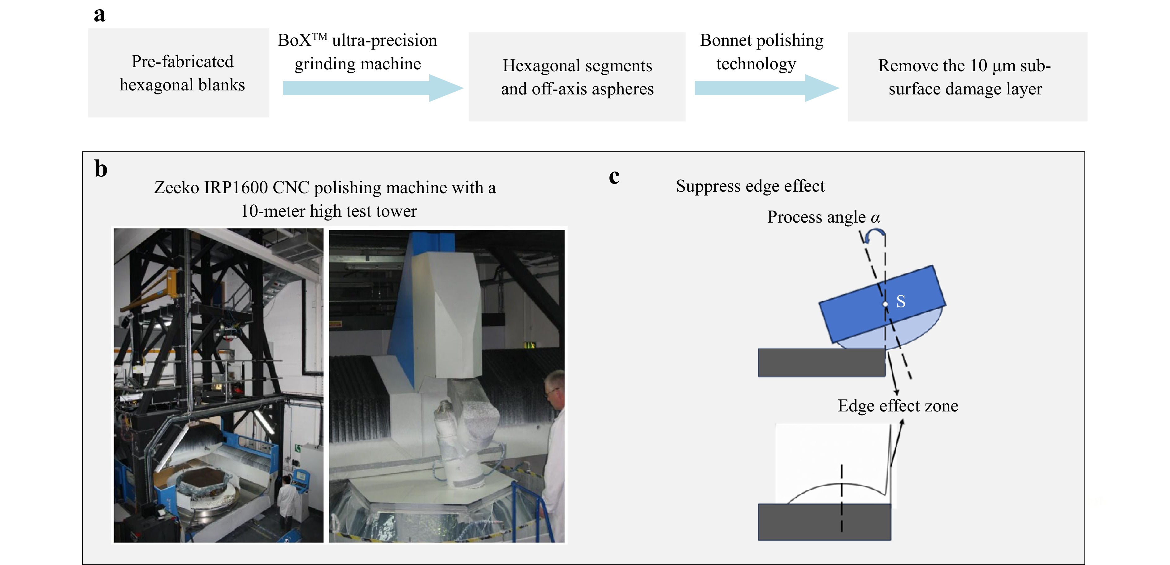
Fig. 14 Novel process chain for grinding and polishing. a Polishing process flowchart. b Zeeko IRP 1600 CNC polishing machine with a 10-meter high test tower. Reproduced with permission82. Copyright 2011, SPIE. c Suppress edge effect.
-
The primary concept of computer-controlled optical surfacing (CCOS) technology is to transform qualitative measurement and processing into quantitative measurement and processing85. The processing equipment utilizes a rigid tool that is significantly smaller than the workpiece86. Based on the discrepancy between the surface data measured by an optical surface profiler and the ideal target surface data, appropriate polishing parameters are selected. A control model for the processing procedure is established, and a dwell time function is generated87. The tool’s path on the workpiece surface, as well as its rotational speed, pressure, and dwell time at each point, are controlled by computer programs to correct surface shape errors and enhance the precision of the workpiece. The core of CCOS technology is deterministic polishing, which has replaced some traditional manual polishing techniques, thereby improving the material removal rate and surface quality of aspheric mirrors.
CCOS technology has also been applied in the fabrication of the 25-meter primary mirror segments of the Giant Magellan Telescope (GMT). The GMT’s primary mirror consists of seven 8.4-meter lightweight honeycomb segments, with one segment at the center and six segments surrounding it. Each primary segment’s backside is actively deformed by 165 load spreaders, working in conjunction with an adaptive secondary mirror to achieve precise alignment and focusing88. As of 2022, six segments have been cast, and three segments have been polished89. Following the principles of CCOS, laps ranging from 4 to 40 cm are used as polishing tools, moving along the mirror’s surface according to a predefined path, as shown in Fig. 15. By controlling the dwell time at different positions, the desired figure is achieved. The 4 cm laps are specifically used during the final polishing cycle and for precise edge correction.
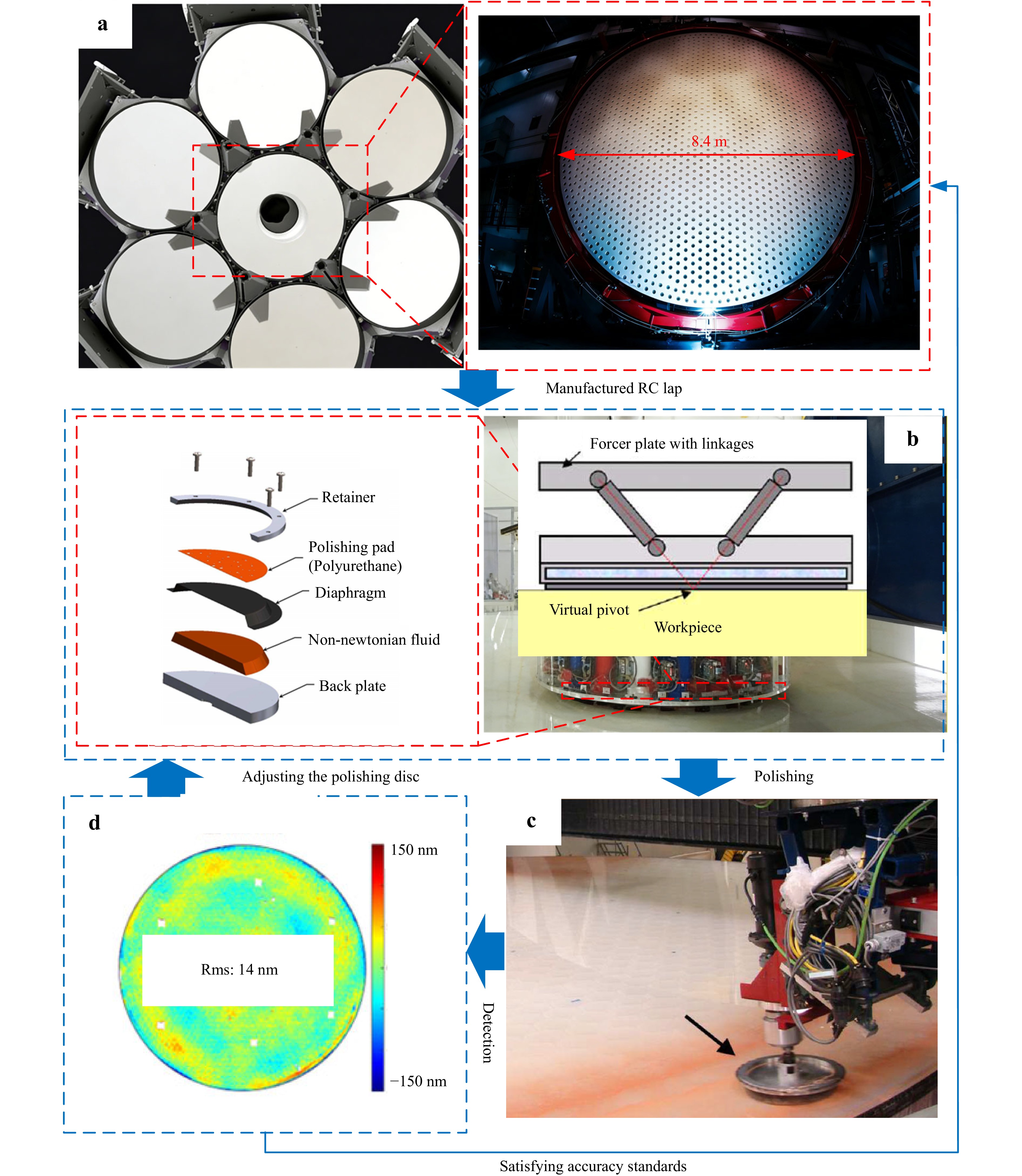
Fig. 15 Manufacturing processes for Giant Magellan Telescope (GMT) mirrors. a GMT rendering and the second Primary Mirror Cast. b Schematic forcer designs of the RC lap structure. Reproduced with permission90. Copyright 2010, Optica Publishing Group. c RC lap polishing on the GMT off axis segment. Reproduced with permission90. Copyright 2010, Optica Publishing Group. d Finished surfaces of GMT.
During the mirror polishing process, full-aperture interferometry and deflectometry are employed for comprehensive aperture measurements, while a 20 cm test plate is used for high-resolution measurements in the edge regions.
Notably, in the GMT polishing process, a rigid conformal polishing tool is utilized to ensure continuous close contact between the tool and the aspheric workpiece within the polishing area. As shown in Fig. 15, this polishing tool uses a non-linear visco-elastic medium as a filler90, known as a rigid conformal (RC) tool. Under high-frequency oscillation of applied stress, the storage modulus of this material is significantly higher than in low-frequency oscillation scenarios. This means that more material removal occurs at local protrusions. The tool has the advantage of adapting to aspheric shapes while maintaining stability, providing a naturally smooth finish. By optimizing the design of the polishing tool, a stable tool influence function (TIF) can be achieved, resulting in a surface roughness of less than 10 Å.
-
Magnetorheological finishing (MRF) technology demonstrates remarkable advantages in astronomical mirror fabrication. Döhring et al.’s global market survey of large astronomical mirror polishing reveals that MRF can efficiently process materials like Zerodur and ULE, achieving a maximum processing aperture of 2.5 meters with surface accuracy of 30 nm PV (5 nm RMS). Notably, MRF excels in correcting “quilting” errors in lightweight mirrors, positioning it as a potential solution for mass production of ELT mirrors91. Sugawara and Maloney’s research on zero-expansion cordierite ceramics (NEXCERA™) confirms that MRF can achieve an ultra-smooth surface of 0.8 nm RMS, with hyperbolic mirror surface accuracy reaching λ/10 (PV 53 nm)80. Deng et al.’s developed hybrid MRF and STP process successfully improved aluminum alloy mirror accuracy to RMS 0.025λ (λ = 632.8 nm) while optimizing roughness to Ra 3-4 nm, addressing the thermal stability issues of traditional nickel-plating processes92. Further studies by Tricard et al. show that MRF can reduce surface errors in ULE and SiC materials from micrometer-level to 22 nm RMS, effectively eliminating “quilting” effects in lightweight structures. When combined with SSI technology, MRF can be extended to larger-aperture mirror fabrication93. Collectively, these studies demonstrate that MRF technology, with its deterministic material removal, high-precision shaping, and adaptability to complex surface geometries, has become a critical process in modern astronomical mirror manufacturing.
-
Ion Beam Figuring (IBF) technology demonstrates advantages in high-precision and deterministic correction in the fabrication of astronomical mirrors. Döhring’s global market research indicates that IBF, as a deterministic correction method, has been successfully applied to large-scale projects such as the KECK telescope. However, its low material removal rate and vacuum environment requirements limit its application in large-aperture mirrors (>2.5 meters)91. Ghigo et al. processed lightweight glass mirrors by combining hot slumping with IBF technology, achieving micron-level surface accuracy and planning to apply it to the fabrication of active adaptive mirrors for next-generation telescopes94. Pradhan et al. employed IBF to correct NiP-coated metal mirrors, reducing the RMS errors of flat and spherical mirrors from 16.3 nm and 13.8 nm to 3.4 nm and 4.4 nm, respectively, and demonstrated that Chemical Mechanical Polishing (CMP) pretreatment could further optimize the RMS to 1.9 nm95. Zheng et al. compared Computer Controlled Optical Surfacing (CCOS) with IBF technology and reduced the RMS error of a spherical mirror from 135.23 nm to 7.04 nm through a combined process, while avoiding the edge effects associated with CCOS96. These studies show that IBF plays an irreplaceable role in nanometer-level surface correction, lightweight mirror processing, and synergistic optimization with other techniques, but requires integration with pretreatment technologies to improve efficiency.
In summary, modern optical polishing technologies, including stressed-mirror polishing, bonnet polishing, CCOS, MRF, and IBF, each demonstrate unique capabilities and limitations in the fabrication of large astronomical mirrors. These techniques collectively address the challenges of achieving nanometer-level precision, deterministic material removal, and mass production efficiency required for next-generation telescopes. The selection of appropriate polishing methods depends on specific requirements such as mirror material, surface geometry, production scale, and desired surface accuracy. Below is a comparative table 2 summarizing the key advantages and disadvantages of these advanced polishing technologies:
Technology Advantages Disadvantages SMP • Mass production efficient
• No edge effects
• IBF compatible• Precise stress control needed
• Limited aspheric typesBP • Freeform capable
• Auto-curvature adaptation
• Fast material removal• Subsurface damage risk
• Edge errors problematicCCOS • Deterministic removal
• Programmable correction
• Flexible tool sizes• Edge tools required
• Slow for large opticsMRF • Quilting error correction
• Nanometer roughness
• Brittle material suitable• >4 m challenges
• Complex system
• Needs hybrid processIBF • Nanometer precision
• No tool wear
• Atomic-level finishing• Slow removal
• Vacuum needed
• Costly for large mirrorsTable 5. Comparison of modern optical polishing technologies
-
In recent years, the application of laser-assisted machining technology in difficult-to-machine materials for astronomical mirrors has garnered widespread attention. Deswal and Kant investigated the machining performance of laser-assisted turning of aluminum 3003 alloy. Experiments revealed that moderate power (300-400 W) could reduce cutting forces, whereas excessively high or low power increased cutting forces and degraded surface quality. Chip morphology varied with power, ranging from continuous small chips to molten chips. Due to material adhesion and tool thermal degradation, the surface roughness in laser-assisted turning (LAT) was higher than in conventional turning, necessitating further parameter optimization and improved cooling methods97. Kun Zhou et al. (2022) proposed a laser-induced ablation-assisted grinding (LIAG) method for machining Cf/SiC ceramic matrix composites, as shown in Fig. 16. By converting the material into loose SiO2 and recrystallized SiC through laser ablation, this method significantly reduced grinding forces, temperatures, and surface roughness while minimizing abrasive wear and surface damage98. Wei Li et al. (2023) studied laser-assisted precision grinding of 3D C/C-SiC composites and found that laser irradiation induced material sublimation, decomposition, and oxidation, forming a porous SiC layer. This reduced grinding forces and specific grinding energy by 43.6% and 43.58%, respectively, while improving surface roughness by 24.22%. The material removal mechanism exhibited a ductile trend99. Yi He et al. (2025) explored the surface formation mechanism of laser-assisted grinding of high-strength TC17 titanium alloy through molecular dynamics simulations and experiments. They discovered that laser assistance reduced grinding forces and generated an ultra-refined grain layer via dynamic recrystallization, minimizing subsurface damage. This validated the advantages of laser-assisted belt grinding in improving surface integrity100. Collectively, these studies demonstrate that laser-assisted machining significantly enhances the efficiency and quality of difficult-to-machine materials through thermo-mechanical coupling effects.
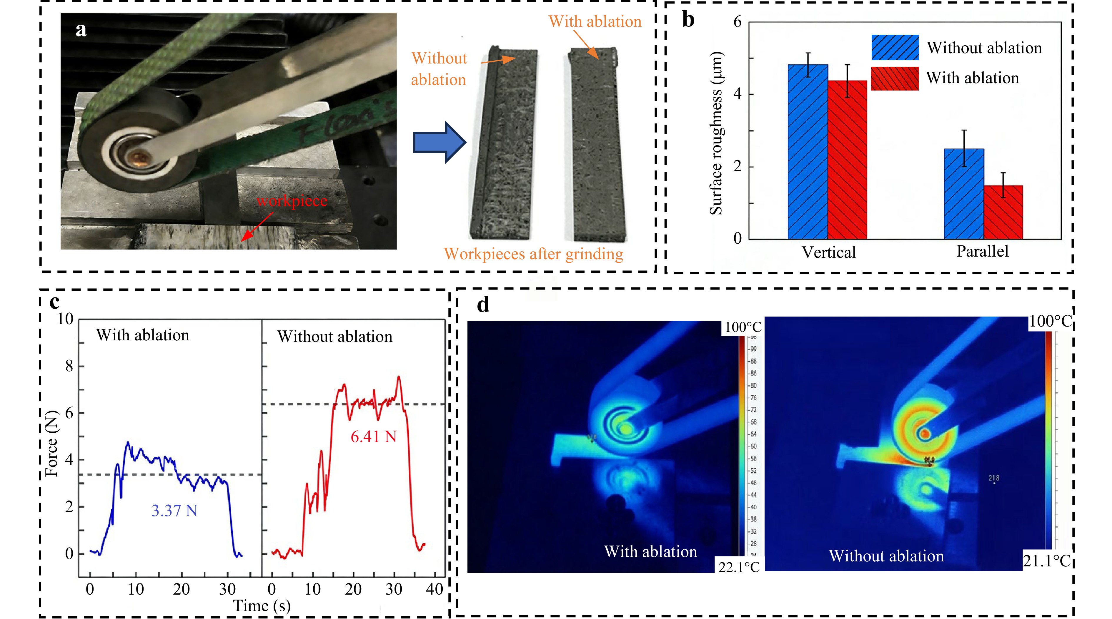
Fig. 16 Experimental analysis of Cf/SiC composites in abrasive belt grinding: a process setup and specimen overview, b post-grinding surface texture evaluation, c measured tangential force characteristics, d thermal distribution during operation. Adapted with permission98. Copyright 2022, Elsevier.
-
Recent studies on the application of ultrasonic-assisted grinding (UAG) technology in machining hard and brittle materials such as ceramic matrix composites (CMCs) and silicon carbide (SiC) have also attracted extensive research interest from scholars. Ran et al. (2023) proposed an ultrasonic-assisted grinding force model that accounts for the anisotropic and heterogeneous characteristics of SiC/SiC composites. By employing a multiscale elastic mechanics model and equivalent fracture toughness analysis, the model predicted normal and tangential grinding forces with average errors of 9.29% and 6.16%, respectively. Their study revealed that fiber orientation significantly influences grinding forces101. Li et al. (2022) developed a discrete numerical model for silicon carbide in two-dimensional ultrasonic-assisted grinding (2D-UAG), incorporating grinding wheel surface topography and material removal mechanisms. Experimental validation showed an average grinding force prediction error of 8.16%. They also found that increasing ultrasonic amplitude initially reduces grinding forces but reaches an inflection point around 5 μm, after which the forces rise102. Zhang et al. (2022) investigated the surface quality and removal mechanisms of SiC/SiC composites in ultrasonic-assisted grinding (UAG). Compared to conventional grinding (CG), UAG significantly reduces grinding forces and surface roughness while minimizing damage such as matrix cracking and fiber debonding. Their experiments confirmed UAG’s advantages in high-efficiency and high-precision machining103. Ding et al. studied the material removal mechanism of silicon carbide ceramics in ultrasonic-assisted grinding (UAG) and found that, under the same parameters, UAG substantially improves machining performance compared to CG: surface roughness decreases by 22.8%, grinding forces and specific grinding energy reduce, and subsurface damage diminishes (microcrack depth decreases by 15–30 μm). Their research indicates that ultrasonic vibration enhances ductile-mode machining and suppresses crack propagation, though the relationship between undeformed chip thickness and critical cutting depth remains crucial104. Collectively, these studies demonstrate that ultrasonic-assisted grinding technology, through high-frequency vibration, effectively enhances the machining performance of hard and brittle materials, reduces grinding forces, and improves surface quality. This provides theoretical support and technical references for the precision machining of complex composites.
-
Materials with low coefficients of thermal expansion, such as silicon carbide (SiC), ULE®, and Zerodur®, are widely used in the construction of space-based telescopes. Among these, SiC is particularly noted for its high specific stiffness and dimensional stability25. To meet the full-spectrum error requirements for precision polishing of large-aperture optical elements, the Changchun Institute of Optics, Fine Mechanics and Physics (CIOMP) has adopted a processing chain that combines CNC generating, stressed lap grinding/polishing, CCOS, and Magnetorheological Finishing (MRF) polishing, as illustrated in Fig. 17. This process model, known as “serial calculation and serial run”, involves the simultaneous calculation of different tool influence functions (TIFs). Each dwell time function is automatically optimized for the full-spatial frequency shape error and the correction capability of the individual tool. This approach has achieved surface metrics of 15.2 nm RMS shape error, 6 nm RMS mid-spatial frequency (MSF) error, and 1 nm RMS roughness on a 4-meter diameter silicon carbide substrate. The core technologies include the development of a new MRF machine based on a robotic arm and a low-temperature silicon PVD cladding technique.
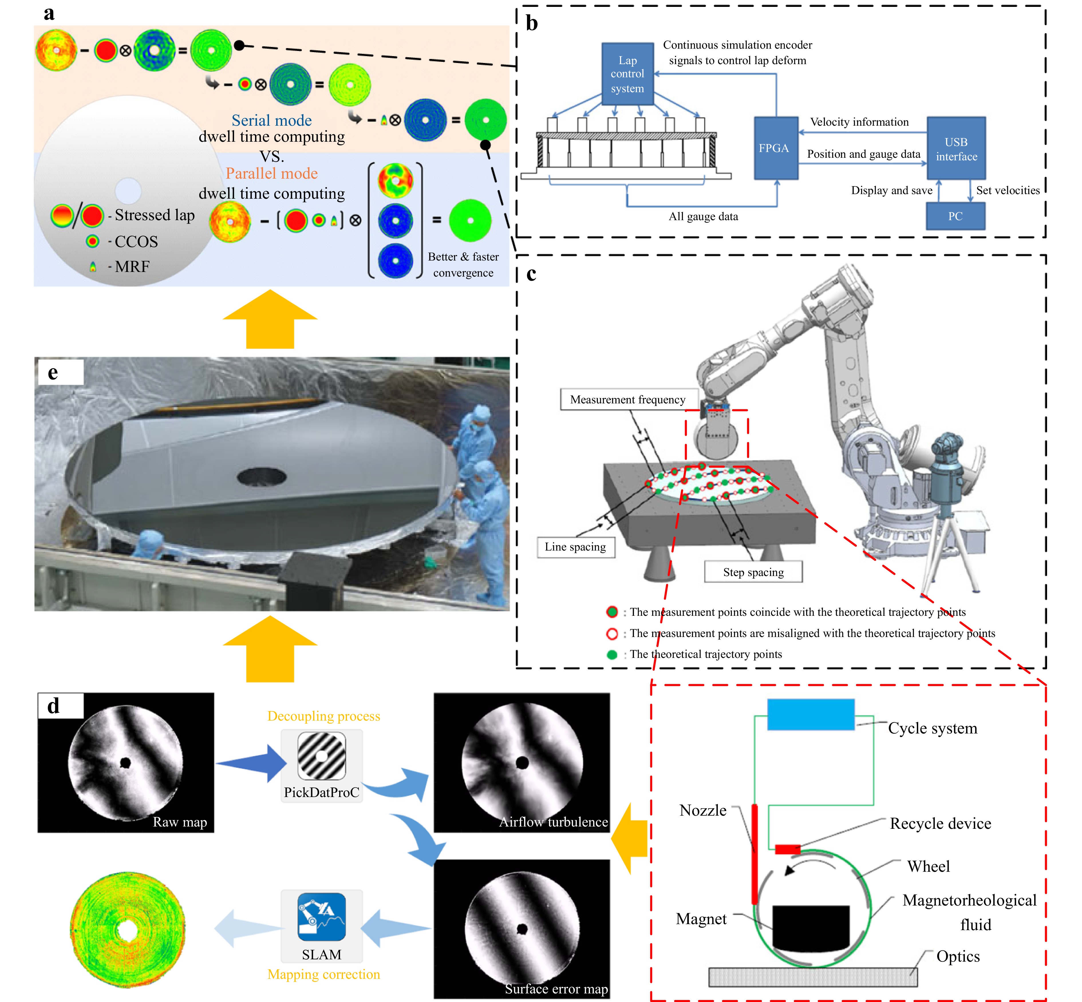
Fig. 17 Manufacturing technology of large aperture telescope mirror for SiC. aThe diagram of parallel calculation and serial run. Reproduced with permission25. Copyright 2022, Springer Nature. b Stressed lap surface measurement system. Reproduced with permission105. Copyright 2016, Optica Publishing Group. c The MRF based on Robot Arm. Reproduced with permission107. Copyright 2022, Optica Publishing Group. d The decoupling algorithm cancels out the effect of air turbulence on large mirror interferometric null test mostly. Reproduced with permission25. Copyright 2022, Springer Nature. e Ø4.03 m SiC mirror after cladding. Reproduced with permission25. Copyright 2022, Springer Nature.
In the initial stages of processing, a stressed lap is used as the polishing tool. As the lap moves and rotates across the mirror surface, it can actively adapt to the curvature variations at different positions on the optical element105. This adaptability enables a broader material removal range and faster processing speeds while simultaneously reducing mid-to-high frequency errors106. This technique offers unique advantages in the polishing of large-aperture optical elements. By strategically configuring the magnetorheological fluid circulation system on the robot arm to ensure stable circulation, CIOMP developed an MRF machine based on the robot arm, demonstrating excellent flexibility107,108. This setup is particularly suitable for manufacturing aspherical or free-form optical elements. Additionally, the lower equipment costs and reduced space requirements make it highly scalable for mass production. These advantages position the MRF machine based on a robotic arm as a highly cost-effective polishing solution. SiC materials are prone to porosity and other defects during manufacturing. One effective method to mitigate these defects is the application of high-density cladding. By depositing a 10–20 μm-thick silicon cladding layer on the surface of the SiC substrate, the density of the polished surface is ensured, significantly enhancing the surface accuracy of the polished results. To more precisely guide the CCOS process, CIOMP has proposed a test data fusion technique that seamlessly integrates data obtained from swing arm profilometry (SAP), CGH null interferometry, and phase deflectometry.
-
X-ray telescopes, as crucial tools for exploring the mysteries of the deep universe, are commonly used to study astrophysical phenomena such as star formation, black hole activity, and gas expansion following stellar explosions. The performance of these telescopes is closely related to the manufacturing quality of the substrate mirrors. X-rays possess unique properties, such as high penetrability and short wavelengths. Therefore, X-ray telescopes typically employ “grazing incidence” techniques, allowing X-rays to enter from the side to enhance reflectivity. The surface roughness of the substrate mirrors must be extremely low. The smoother the mirror, the closer the reflectivity is to the theoretical value. Hence, developing efficient and precise substrate manufacturing technologies is of paramount importance. The manufacturing methods for X-ray telescope substrates include direct polishing35,109, replication110,111, forming, bent silicon wafer methods, and single-crystal silicon slicing.
Replication is a manufacturing technique that transfers surface features to the substrate using high-precision molds112. In the manufacturing of X-ray telescope substrates, replication methods include nickel electroforming deposited and aluminum-based epoxy replication. nickel electroforming deposited involves immersing a mold coated with a reflective layer into a nickel electroplating bath, allowing nickel to deposit on the layer. By separating the nickel layer from the mold, a reflective mirror with high reflectivity and good surface quality is obtained. This method allows the mold to be reused and reduces the manufacturing cost. It has been widely used in several significant X-ray telescope, such as BeppoSAX, and Apollo113. etc. Aluminum-based epoxy replication is a lightweight mirror manufacturing method. It first coats a glass mold with reflective and separation layers. By spraying epoxy resin adhesive, an aluminum alloys sheet with a treated surface is bonded to the mold. After the epoxy resin cures, the aluminum alloys substrate is separated from the layers to obtain the reflective mirror. This method produces lightweight mirrors and has been applied in projects like ASTRO-E and ASTRO-H111,114.
Thin thermally shaped thin replication is an efficient process for manufacturing X-ray telescope mirrors. This method involves heating thin glass to soften it and then conforming it to a mold with a specific shape to replicate the desired mirror shape115. Depending on the contact method between the mold and the mirror, it is divided into direct thermal shaped and indirect thermal shaped. In direct thermal shaped, the mirror directly contacts the convex mold, resulting in high shape accuracy; indirect thermal shaped allows for more complex molds but requires addressing bubble issues. This process is cost-effective and efficient, suitable for mass production of high-precision mirrors. It has been successfully applied in several X-ray telescope, such as Athena116,117, demonstrating its broad application prospects in the field of astronomy.
-
This review systematically examines the development of astronomical telescope mirror manufacturing technologies, revealing a complete technical chain that progresses from material innovation to full-spatial-frequency error control. The evolution of this precision manufacturing system fundamentally aims to overcome the inherent limitations of next-generation extremely large telescopes in terms of lightweight structures, thermal stability, and nanometer-level surface accuracy.
Currently, the deep integration of new material systems—such as silicon carbide and beryllium-aluminum alloys—with advanced manufacturing processes like ultra-precision diamond turning, stressed-lap polishing, and magnetorheological finishing, has enabled effective control of surface figure accuracy and mid-to-high-frequency errors at the nanoscale. In particular, the innovation of segmented primary mirror architectures has not only broken through the size limitations of single mirrors but has also driven a strategic shift in manufacturing paradigms from “precision crafting of individual pieces” to “batch intelligent manufacturing”. The introduction of robotic production lines, digital twin technology, and hybrid process strategies has significantly enhanced the batch manufacturing capabilities for projects such as the Extremely Large Telescope (ELT).
However, technological development still faces three core challenges: the stable achievement of sub-nanometer surface roughness, precise control of machining-induced subsurface damage, and long-term performance maintenance under extreme space conditions. These challenges necessitate the establishment of more intelligent manufacturing systems, the development of new functional coating materials, and the construction of sustainable large-scale production processes.
Based on an in-depth analysis of the current technological status and challenges, several key directions for future development can be envisioned. These directions not only reflect the inherent logic of technological evolution but also respond to the urgent needs of astronomical observation science. Specifically, future breakthroughs will focus primarily on the following three dimensions:
-
Future technological development will no longer be confined to isolated improvements in single processes but will emphasize coordinated design and integration across the entire chain from materials to systems. This entails:
Material-process co-design: The selection of mirror materials will be deeply coupled with their specific manufacturing processes (e.g., stressed-lap polishing, ion beam figuring). For instance, tailored directional grinding and deterministic polishing strategies must be developed for anisotropic materials like SiC and silicon carbide fiber-reinforced composites to control mid-spatial-frequency errors at their source.
Closed-loop integration of manufacturing and metrology: The “machining-measurement” iteration cycle will be compressed through in-process and on-machine measurement technologies, enabling real-time feedback and compensation during manufacturing. Digital twin technology will play a key role here, simulating the physical manufacturing process in virtual space to predict and optimize process parameters, thereby achieving proactive suppression of full-spatial-frequency errors, particularly the challenging mid-spatial-frequency errors.
-
Segmented primary mirrors have fundamentally altered the manufacturing paradigm for large telescopes. The core future challenge lies in seamlessly transferring and maintaining the manufacturing precision (nanometer-level) of hundreds of mirror segments at the system-level co-phasing accuracy (nanometer-level). This demands that future research transcends the traditional scope of “lens processing” and directly addresses system integration issues:
Edge effects and co-phasing accuracy: The edge quality of segments (edge taper, roll-off) directly determines the final performance of system integration. Developing deterministic edge figuring technologies capable of simultaneously controlling the surface figure accuracy and edge geometry of segments is a prerequisite for achieving efficient co-phasing.
Batch manufacturing consistency: For projects like the ELT requiring thousands of segments, the consistency and efficiency of batch manufacturing are decisive factors for cost and schedule. This necessitates the development of robotic and AI-enabled flexible smart manufacturing cells to achieve efficient and highly consistent batch production of segments.
From “Lens” to “Opto-mechanical system”: The final imaging quality results from the combined effects of mirror manufacturing, active optics, wavefront sensing, and control. Therefore, future manufacturing technologies must consider opto-mechanical co-design, for instance, by incorporating compensatory measures during the manufacturing stage for surface deformations induced by active support forces or thermal loads in space.
-
The forefront of astronomical science places unprecedented demands on telescope performance, driving the development of a series of enabling technologies:
Extreme contrast imaging: Requirements such as direct detection of exoplanets impose nearly stringent demands on the control of mid-spatial-frequency error scatter and thermal stability within the system. This calls for the development of sub-nanometer roughness polishing techniques and stress-free mounting and coating technologies.
Multi-wavelength and wide field of view: Observations spanning X-ray to infrared wavelengths require the development of novel broadband high-reflectance films and freeform surface manufacturing and metrology technologies to simultaneously meet the performance requirements of different bands and enable more compact optical system layouts.
Intelligent and sustainable manufacturing: Artificial intelligence will play a central role in process optimization, error diagnosis, and predictive maintenance. Concurrently, reducing manufacturing energy consumption and developing recyclable mirror body materials will become essential considerations for future large-scale optical engineering projects.
In conclusion, the manufacturing technology for astronomical telescopes is evolving from a precise “craft” into a highly complex “systems engineering” discipline. Its success depends not only on continuous breakthroughs in unit technologies—progressing along the chain “from materials to full-spatial-frequency error control”—but, more critically, on our ability to successfully solve the system-level challenge of batch manufacturing, system integration, and active control of segmented mirrors. This path will ultimately determine the scale of the telescopes we can build and the clarity with which we can observe the depths of the universe.
A review of manufacturing technology progress for astronomical telescope mirrors— from material innovation to Full-Spatial-Frequency error control
- Light: Advanced Manufacturing , Article number: 35 (2026)
- Received: 27 April 2025
- Revised: 02 March 2026
- Accepted: 03 March 2026 Published online: 23 March 2026
doi: https://doi.org/10.37188/lam.2026.035
Abstract: The relentless pursuit of higher resolution and sensitivity in astronomical observation drives the advancement of telescope mirror manufacturing. This review systematically charts the technological evolution from material innovation to the deterministic control of full-spatial-frequency errors. We analyze the progression of substrate materials—including silicon carbide, beryllium alloys, and advanced glass-ceramics—focusing on their critical thermomechanical properties for extreme environments. The core manufacturing chain is thoroughly examined: ultra-precision diamond turning for initial form generation, grinding processes exploiting brittle-to-ductile transitions, and advanced polishing techniques like magnetorheological finishing and ion beam figuring that achieve nanometer-level accuracy. A central theme is the paradigm shift towards segmented mirrors, which necessitates solving system-level challenges in edge control, co-phasing, and high-consistency batch production. The integration of field-assisted machining and intelligent systems, such as digital twins and robotics, is highlighted as a key enabler for next-generation manufacturing. While significant progress is evident, core challenges persist in stable sub-nanometer finishing, subsurface damage mitigation, and long-term performance under operational extremes. Future development hinges on deeper material-process co-design, fully integrated metrology-manufacturing loops, and sustainable production frameworks. This synthesis provides a comprehensive technical foundation for developing the extreme optical systems required for future discoveries in astrophysics.
Research Summary
Telescope mirrors: From materials to full-spectrum precision
Astronomical telescopes require ever-larger mirrors to achieve higher resolution and sensitivity, but there are major challenges in weight, thermal stability and surface accuracy. This Review surveys recent progress in astronomical telescope mirror manufacturing, covering the full technology chain from material innovation to deterministic control of full-spatial-frequency surface errors. Key mirror materials are compared for performance and manufacturability under extreme conditions. The article reviews advanced shaping, grinding and polishing techniques—such as ultra-precision diamond turning, stressed-mirror polishing, magnetorheological finishing and ion beam figuring—that enable nanometer-level surface control. Emphasis is placed on segmented primary mirrors, where batch consistency, edge control and system-level integration are reshaping manufacturing paradigms. The Review highlights emerging trends toward intelligent and integrated manufacturing systems for next-generation extremely large telescopes.
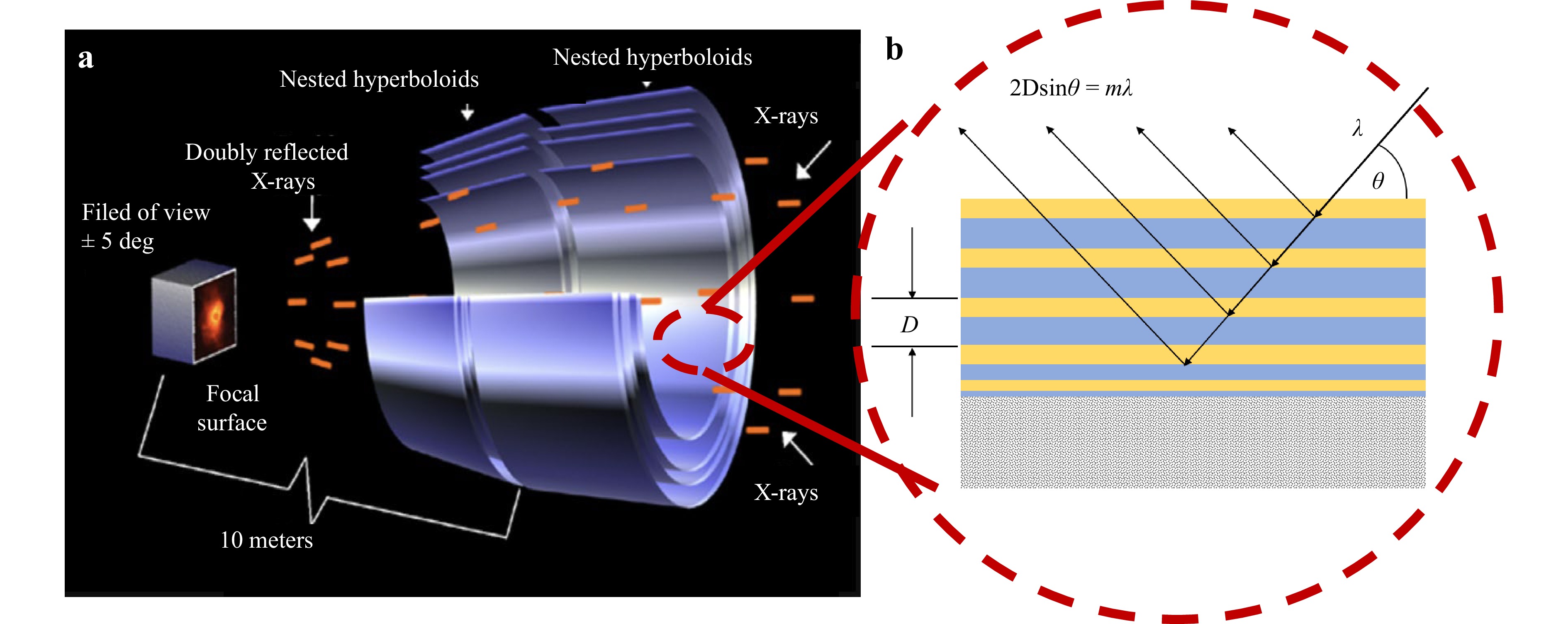
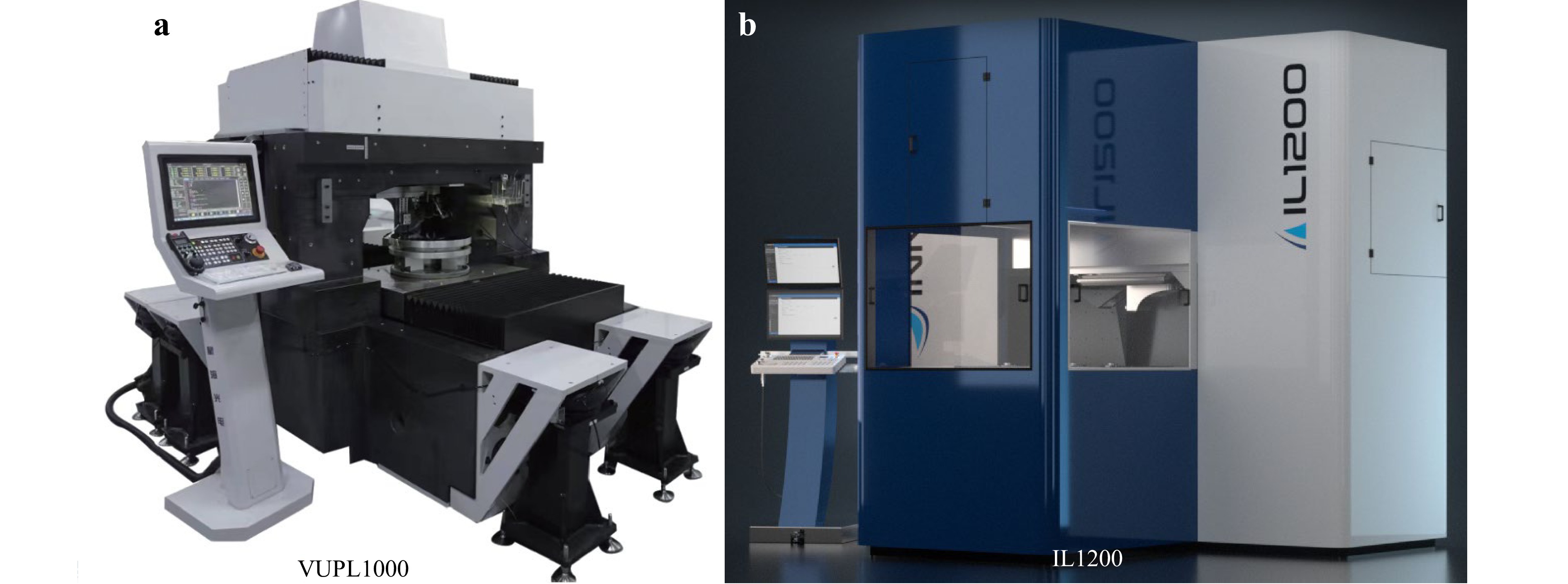
Rights and permissions
Open Access This article is licensed under a Creative Commons Attribution 4.0 International License, which permits use, sharing, adaptation, distribution and reproduction in any medium or format, as long as you give appropriate credit to the original author(s) and the source, provide a link to the Creative Commons license, and indicate if changes were made. The images or other third party material in this article are included in the article′s Creative Commons license, unless indicated otherwise in a credit line to the material. If material is not included in the article′s Creative Commons license and your intended use is not permitted by statutory regulation or exceeds the permitted use, you will need to obtain permission directly from the copyright holder. To view a copy of this license, visit http://creativecommons.org/licenses/by/4.0/.

 DownLoad: