


HTML
-
Biological systems have long provided examples of structural and functional solutions with properties that far exceed those of numerous engineered materials. The systematic transfer of these properties to technological design, known as biomimetics, has expanded rapidly with the development of advanced fabrication techniques. In particular, modern additive manufacturing enables the rapid production of complex three-dimensional architectures that closely reproduce or intentionally modify biological geometries, allowing examination of their physical properties under controlled conditions1, 2. In this paper, we focus on diatom microalgae, whose silica frustules represent some of the most intricate naturally occurring photonic architectures3, 4. Diatoms are unicellular microalgae ranging from a few micrometres to several millimetres in size and encompassing a wide diversity of species with distinct morphologies. They constitute a major component of the global phytoplankton community, contributing roughly 20% of the Earth's oxygen production and accounting for about a quarter of the marine biomass5. They inhabit a wide range of aquatic environments with strongly varying conditions, including salinity, light availability, and nutrient levels6. The diatom frustule is a hydrated shell with an intricate pattern and a multilayered architecture with components ranging from nano- to microscale7. This biosilica "casing" performs several essential functions: it mechanically stabilises and protects the cell8, regulates the exchange of nutrients and metabolites through its porous network9, and influences the hydrodynamic properties of the organism by helping it maintain its position in the water column10. Additionally, the frustule affects the organism’s optical environment, enhancing light capture for photosynthesis while simultaneously attenuating harmful ultraviolet radiation11, 12. Due to these structural and optical features of diatom biosilica, major efforts have been made to exploit it in various technologies13, 14, ranging from biosensing platforms15 and microfluidic-integrated detection systems16 to filtration membranes17 and high-sensitivity surface-enhanced Raman scattering (SERS) substrates18, 19. The diatom frustule functions as a biologically derived photonic crystal whose periodically arranged pores and ribs give rise to a variety of light-manipulation phenomena12, 20. Previous studies have attributed several photonic features to the frustule, including diffraction-based focusing21−23, in-plane waveguiding along silica ribs or pore arrays23, thin-film interference caused by the multilayered valve architecture11, and grating-like spectral filtering linked to ordered areolae24. These studies demonstrate that natural frustules actively redistribute light in the visible spectral range. Beyond localised focusing, diffraction patterns, and waveguiding effects11,20,22,24,25, the ordered pore lattices of numerous centric diatoms resemble periodic diffractive membranes. Such structures are capable of supporting axial self-imaging governed by near-field diffraction. In this context, the Talbot effect, defined as the self-imaging of a periodic structure under coherent illumination, provides a natural framework for describing longitudinal field recurrence26. For a periodic lattice with the lateral period d, the axial recurrence distance (Talbot distance) is determined by the wavelength $ \lambda $ in the surrounding medium and can be estimated using the Rayleigh expression27:
$$ \begin{aligned} L_t = \frac{\lambda}{1 - \sqrt{1-\dfrac{\lambda^2}{d^2}}} \end{aligned} $$ (1) In our previous work28, we simulated light propagation in the Coscinodiscus oculus-iridis frustule using the Fourier modal method and demonstrated that the structure can support Talbot diffraction in water. Our calculations showed that the valve behaves as a naturally occurring diffractive element with well-defined near-field periodicity governed by its lateral pore arrangement.
Fig. 1 illustrates an estimated near-field diffraction pattern for a one-dimensional grating with a 1 µm period. Rapid variations in the vertical features are caused by wavelength-scale interference, while slower, larger-scale modulation indicates the Talbot diffraction pattern.
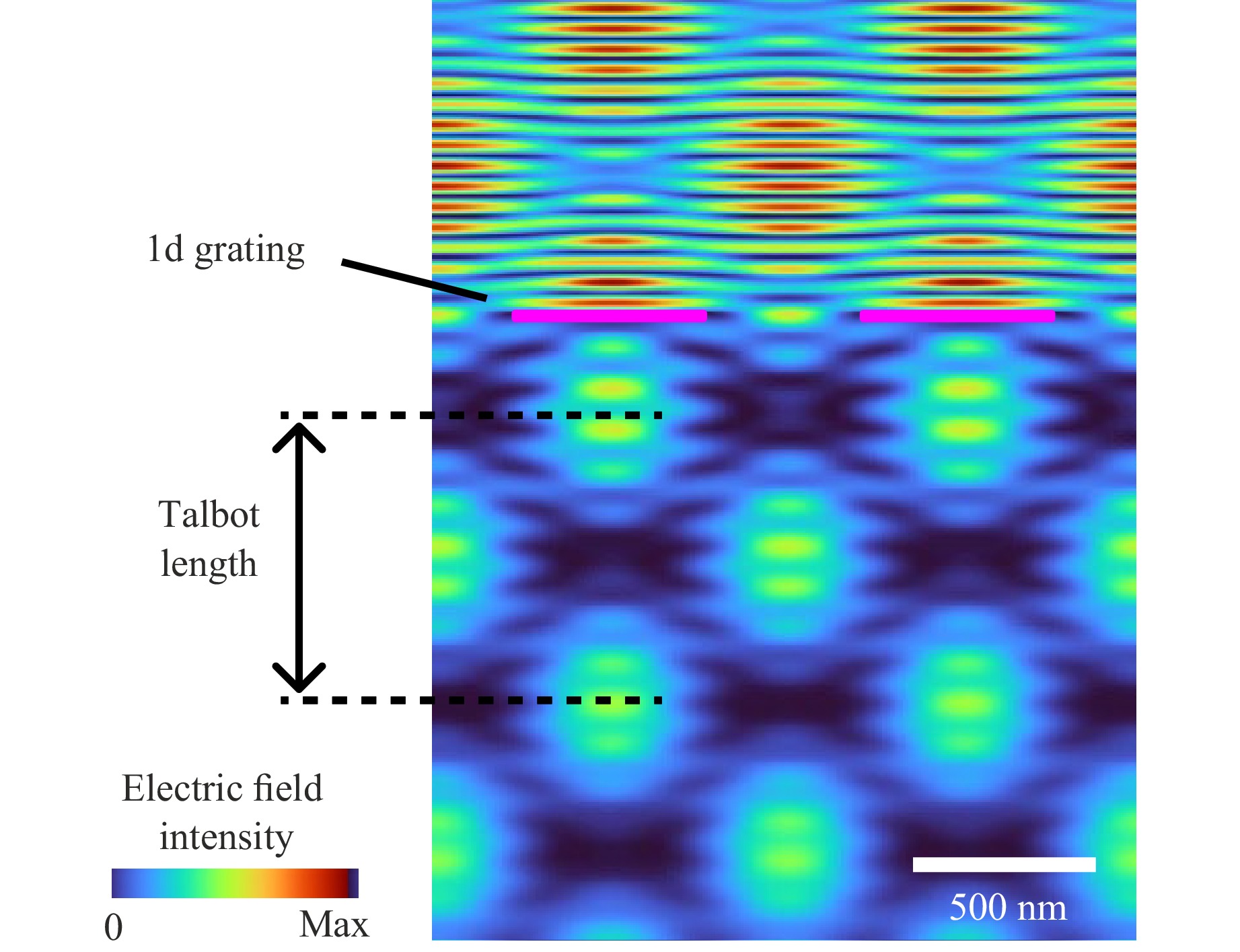
Fig. 1 Numerical illustration of the Talbot diffraction pattern based on a one-dimensional grating. The calculation was performed for a wavelength of 500 nm, a horizontal period of 1 µm, material stripes with a permittivity of $ \varepsilon = 15 $, a thickness of 50 nm, and a width of 500 nm. The small vertical period is due to the vertical interference, on the order of the wavelength. The large vertical period corresponds to the Talbot effect.
The Talbot effect has been widely explored in optics. Both theoretical and experimental studies have demonstrated self-imaging in periodic structures ranging from micron-scale gratings to lithographically defined metasurfaces29, 30. In these studies, the formation of integer and fractional Talbot planes under well-controlled conditions and at wavelengths spanning the visible to the THz range has been established31−33. Near-field Talbot diffraction has also been observed experimentally for one-dimensional gratings in the THz regime33, providing a clear reference for understanding self-imaging in ideal periodic media.
Applying these concepts to natural diatom frustules requires careful consideration of their structural complexity. In contrast to ideal planar gratings, diatom valves combine submicron pores, multilayered geometry, and intrinsic curvature34. Theoretical analysis predicts Talbot distances on the order of a few micrometres28, a scale compatible with the resolution of modern near-field optical techniques. However, resolving the full longitudinal field evolution within an intact three-dimensional biological structure necessitates controlled axial scanning with high spatial precision, as well as careful separation of multiple overlapping diffraction mechanisms. To enable systematic investigation of axial self-imaging behaviour, we employ geometric scaling in the THz regime implemented through additive manufacturing. Rather than attempting to replicate the frustule at its native micron and submicron dimensions, which exceed the resolution limits of commercial 3D-printing technologies, we enlarge the geometry while preserving its lateral periodicity and the dimensionless ratio $ \lambda $/d. The optical response is then probed at proportionally longer wavelengths in the THz range. This strategy extends the Talbot distance to the millimetre scale, enabling direct spatial mapping of the longitudinal field evolution. Previous efforts to replicate diatom architectures have primarily focused on structural or mechanical aspects35−39, whereas here we specifically tailor the replication for optical investigation. Therefore, the combination of geometric scaling, terahertz illumination, and controlled additive manufacturing provides an experimentally accessible platform for demonstrating Talbot diffraction in diatom-inspired geometries.
-
To enable controlled experiments, artificial diatom-inspired structures were fabricated using scanning electron microscopy (SEM) images of natural frustules of Coscinodiscus oculus-iridis (Ehrenberg) Ehrenberg 1840 (phylum Bacillariophyta, class Coscinodiscophyceae) as geometric templates. A comparison between the native silica architecture and its scaled polymer replica is shown in Fig. 2. Fig. 2a schematically shows the silica frustule obtained from a living centric diatom cell through chemical treatment that removes the cellular components while retaining the original porous structure. Fig. 2b shows a high-resolution cross-section of a valve element, revealing the characteristic multilayer organisation of the frustule. In centric diatom valves, the foramen refers to the relatively large, micrometre-scale openings forming the inner perforated plate of the valve8. These features primarily define the lateral periodicity relevant for diffraction. The cribrum is a thin, sieve-like outer layer consisting of much smaller pores, typically tens to hundreds of nanometres in size, which mainly regulate mass transport and provide mechanical protection8. These two perforated layers are connected by an intermediate silica framework formed by the areola walls, which create a honeycomb-like network that provides structural stability and defines the internal chamber geometry of the valve8, 28. The spatial arrangement of these layers and the corresponding cross-sectional view are presented in Supplementary Fig. S1. This internal organisation is also visible in Fig. 2c, where the cribrum layer on the upper valve surface was selectively removed by etching. Fig. 2d presents an overview of the complete frustule morphology.
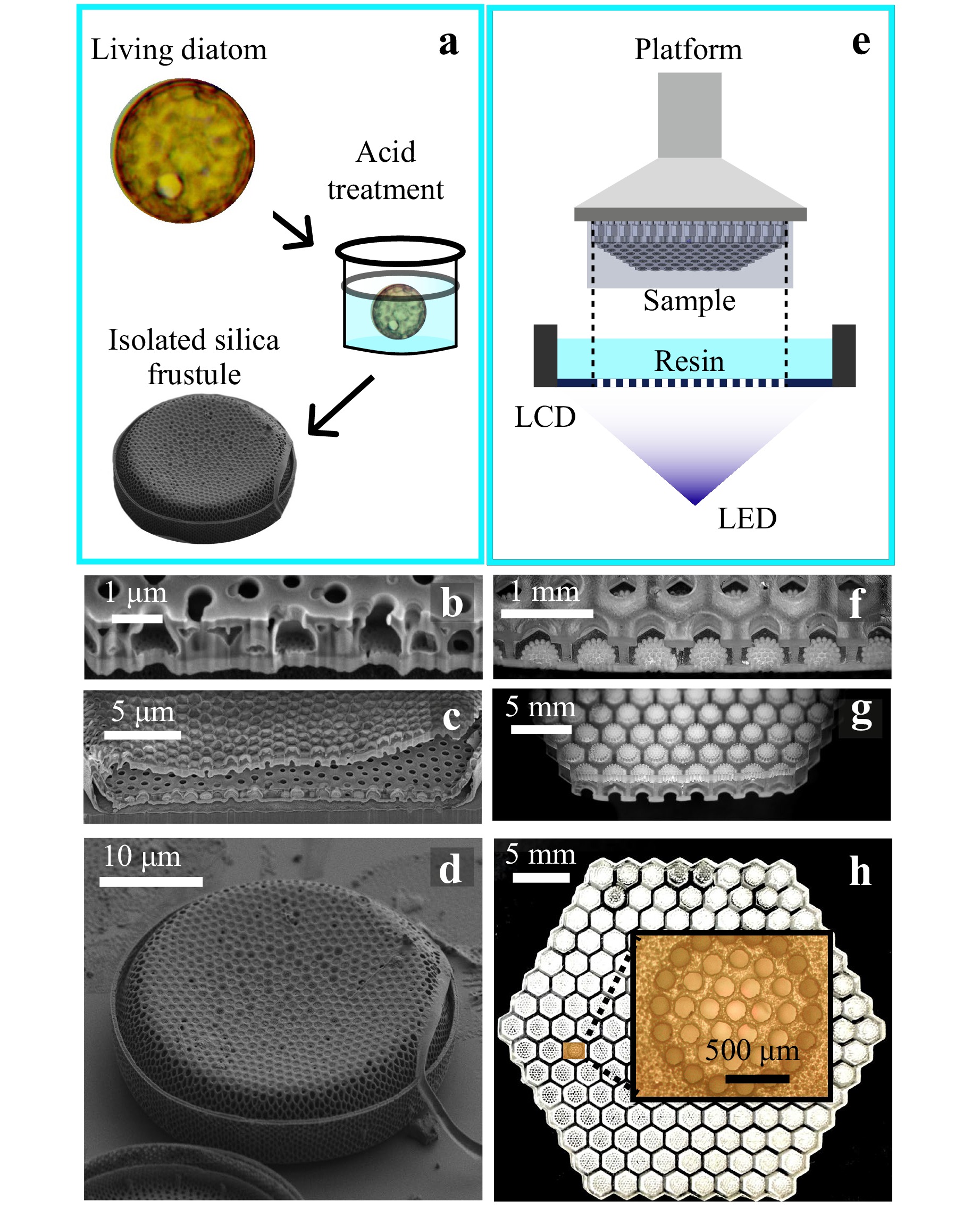
Fig. 2 Natural and artificial diatom photonic architectures. a Schematic illustration of the isolation of a silica frustule from a living centric diatom using chemical treatment. b-d SEM images of the centric diatom C. oculus-iridis, illustrating the fine multilayered structure of the valve wall b, the inner surface and pore distribution c, and the overall frustule morphology d. e Schematic representation of the LCD-based additive manufacturing process used to fabricate scaled polymer structures. f-h LCD-printed polymer model scaled by a factor of approximately 2,000, replicating the hierarchical pore lattice and rib network of the natural frustule: f cross-sectional view, g side view, and h top view, where the inset highlights the periodic pore arrangement.
Fig. 2e illustrates the LCD-based additive manufacturing process used to fabricate the scaled polymer structures shown in Fig. 2f-h. The model was uniformly enlarged by a factor of $ \approx $ 2,000 to enable experimental investigation at THz wavelengths. This factor was chosen to match the operating wavelength of 911 µm to the emission maximum of the radiation source. At this wavelength, the source provides the highest output power, resulting in an improved signal-to-noise ratio under the experimental conditions.
The recalculation was based on the assumption that in the natural aqueous environment the absorption of blue light with a wavelength of approximately 420 nm is lowest, resulting in the most effective interaction with diatom frustules. A detailed description of the recalculation procedure is provided in the Materials and Methods section.
Fig. 2f shows a magnified fragment of the cross-section of the printed structure, while Fig. 2g presents a side view of the same fragment at a different magnification. Fig. 2h presents a top view of the structure; the highlighted region corresponds to a higher-magnification view in which the periodic pore lattice is visible. An enlarged view of the cribrum layer, clearly showing the perforated plate geometry with an array of cylindrical pores, is provided in Supplementary Fig. S2.
To study the diffraction properties of the sample, THz continuous-wave raster scanning was used to map the spatial intensity distribution of radiation transmitted through the sample. The experimentally obtained near-field diffraction patterns for the investigated samples are shown in Fig. 3. The intensity distribution was measured both along and perpendicular to the radiation propagation direction. The scan area along the propagation direction was 5 × 24 mm2, while the scan area perpendicular to it was 6 × 6 mm2.
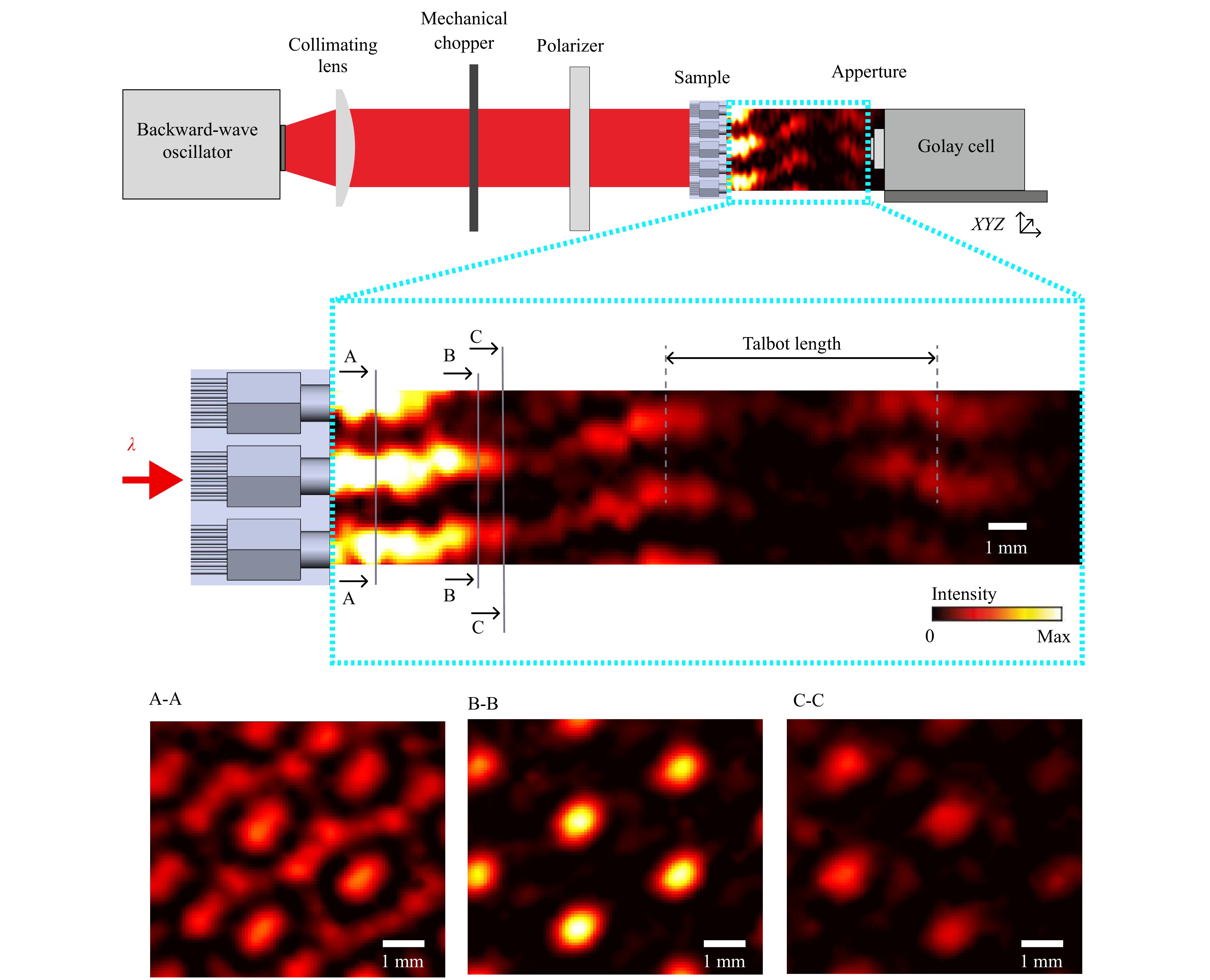
Fig. 3 Radiation intensity distribution behind a diatom frustule-like structure. Top: schematic representation of the continuous-wave THz raster-scanning imaging system. Middle: longitudinal map of the normalised radiation intensity recorded along the optical axis behind the structure at a wavelength of 911 µm; electromagnetic radiation propagates from left to right. Bottom: transverse intensity distributions measured perpendicular to the propagation direction at three selected planes (A–A, B–B, and C–C), located at distances of 1.02 mm, 4.60 mm, and 5.35 mm from the structure plane, respectively. The colour scale represents the normalised radiation intensity.
The upper panel in Fig. 3 illustrates the experimental configuration and measurement geometry, while the central panel presents a longitudinal intensity map recorded along the optical axis behind the frustule-like structure at a wavelength of 911 µm. Electromagnetic radiation propagates from left to right, and the colour scale represents the normalised intensity distribution. Perpendicular cross-sectional intensity maps were recorded at selected distances from the structure plane, corresponding to positions A–A, B–B, and C–C, located at 1.02 mm, 4.60 mm, and 5.35 mm, respectively. These planes are indicated on the longitudinal intensity map and are shown as individual panels in the lower part of Fig. 3. At the shortest distance (A–A), the diffraction pattern reflects the superposition of contributions from different structural layers of the frustule-like geometry. Features associated with both the honeycomb rib network and the pore-filled layer are simultaneously visible, resulting in a complex near-field interference pattern. At the intermediate distance (B–B), the intensity distribution evolves into a set of well-defined localised maxima, corresponding to radiation focusing. The spatial arrangement of these focal spots reproduces the periodicity of the pore-filled layer of the structure. The measured intensity at these focal points reaches approximately half of the incident beam intensity. This value corresponds specifically to the local peak intensity at the focal maxima and represents the maximum of the normalised intensity distribution at the given propagation plane. Further propagation beyond this plane (C–C) leads to degradation of the focusing effect. The localised intensity maxima become broader and less pronounced, indicating that the focusing is a local near-field phenomenon that is sensitive to the propagation distance. Displacement from the optimal plane results in a rapid loss of brightness and contrast in the focal spots. During the experiment, a Talbot diffraction period of approximately 10 mm was observed, which is consistent with the expected near-field diffraction behaviour of the periodic frustule-like architecture.
-
A simulation was carried out using the Fourier modal method, taking into account the refractive indices, wavelength, and structure dimensions relevant to experiments in the THz range. For the frequency of $ \nu=0.329 $ THz ($ \lambda = 911\; $µm), the average value of the complex refractive index is $ \tilde{n}=1.68-i0.03 $. Despite the relatively high absorption, the calculations indicate that Talbot diffraction should still be observable in this case. However, the resulting pattern is expected to be less intense than that in the visible spectral range28.
Fig. 4 presents the results for calculating the field distribution for a Gaussian beam incident on the structure. The simulation was performed for a beam with attenuation taken into account, and it covers the entire region where the electric field intensity remains sufficiently high. The region where the Gaussian beam intensity remains sufficiently high corresponds to an area of 30 × 30 mm2 (transverse) and 50 × 50 mm2 (along the propagation direction). The two upper panels in Fig. 4 show a cross-section along the radiation propagation direction. Cyan dotted callouts indicate an enlarged cross-section corresponding to the region observed experimentally. The Talbot period was $ \approx $ 10 mm. In the experiment, the fine structure of the intensity maxima was not resolved. The letters A, B, and C denote cross-sections perpendicular to the radiation propagation direction. These sections are located at coordinates corresponding to the experimental positions: 1.02 mm for section A–A, 4.60 mm for section B–B, and 5.35 mm for section C–C. Each section is shown both for the entire beam and for the corresponding region. The full beam is displayed within a 30 × 30 mm2 square, while the cyan squares correspond to regions of 6 × 6 mm2. The Talbot diffraction pattern is highly sensitive to the exact coordinates; therefore, even small uncertainties in determining the experimental positions could lead to noticeable differences between the calculated distributions and experimental images.
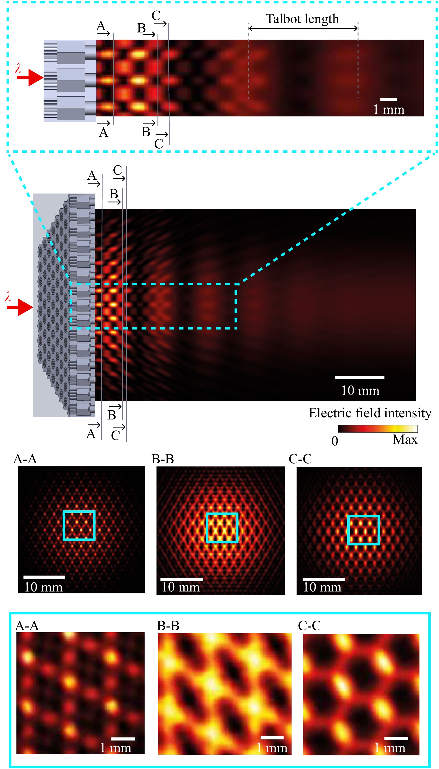
Fig. 4 Electric field distribution. Gaussian beam with half angular divergence of $ a_o = 1.4^\circ $, beam waist radius $ w_o = 12 $ mm, wavelength $ \lambda = 0.9 $ mm, half of the focal depth $ z_o = 480\; $ mm, polar angle of incidence $ \theta_0 = 0^\circ $, azimuthal angle of incidence $ \phi_o = 0^\circ $, and the centre of the beam waist located on the front plane of the structure (the cribrum layer). The electric field is averaged over the polarisation states of the incident light. The calculated areas corresponding to the experimental observations are highlighted in cyan.
-
The results presented in this study provide experimental confirmation of near-field Talbot diffraction in a diatom-inspired multilayer photonic structure in the THz regime. While Talbot diffraction is a well-established phenomenon in classical and quantum optics29, 31, and has been demonstrated in one-dimensional THz gratings33, its observation in a biomimetic, three-dimensional, quasi-periodic structure replicating the diatom Coscinodiscus architecture extends these concepts beyond ideal planar systems. Our findings bridge the gap between theoretical predictions of near-field interference in natural frustules28 and their realisation using scalable additive manufacturing.
The fabricated models (Fig. 2f-h) replicate the natural multilayer architecture of the diatom frustule (Fig. 2b-d), enabling the distinct optical roles of individual layers to be examined. The foramen layer was realised as a strictly periodic radial array, while the cribrum layer, although printed with a similar pore arrangement, differs from its natural counterpart, where such an arrangement is less pronounced. It is important to note that the characteristic periodicity of the cribrum (~225 µm in the scaled model) is much smaller than the operating wavelength (911 µm), placing it in a subwavelength regime (~λ/4). Therefore, this layer behaves as a homogeneous medium, which is consistent with the theoretical expectation that structures with features significantly smaller than the wavelength do not produce distinct diffraction patterns. No Talbot diffraction associated with the cribrum was observed experimentally, and its optical impact is limited in terms of near-field interference. This observation is consistent with the findings of numerical analyses by Ghobara et al.40, who showed that Talbot fringes appear only in frustule elements whose periodicity is comparable to the wavelength, while subwavelength grid-like features primarily act as effective media without producing self-imaging effects.
This layered analysis clearly shows that the foramen layer and the intermediate honeycomb-like areola walls primarily contribute to the observed Talbot diffraction. These structural elements have lateral periodicities comparable to the radiation wavelength, with a ratio of $ {\lambda}/{d}\; \approx\; 0.4\; = $ 911/2,280 µm in the scaled model, favouring pronounced near-field interference. In this respect, our experimental results are consistent with the Talbot-type interference patterns predicted by Ghobara et al.20 for grid-like and lattice-like components of pennate diatom frustules in the optical regime. While their study relied on frequency-domain simulations of two-dimensional cross-sections at visible wavelengths, our work extends this interpretation by experimentally demonstrating Talbot diffraction behind a three-dimensional, multilayer frustule-like structure scaled to the THz domain. Fig. 3 summarises the near-field intensity distributions formed behind the frustule-like structure under THz illumination at a wavelength of 911 µm as measured experimentally. The longitudinal intensity map reveals a clear modulation of the transmitted field along the propagation direction, with the reappearance of structured transverse intensity patterns at specific distances from the sample. This behaviour is characteristic of Talbot diffraction arising from periodic structural elements whose lateral dimensions are comparable to the radiation wavelength. The key experimental observation is the simultaneous repetition of two distinct transverse patterns: a honeycomb-like intensity distribution associated with the areola wall network, and a periodic pattern formed by the array of large openings (foramen), as shown in Fig. 3, section A–A. The experimental intensity maps are shown in a smoothed form. Discrepancies between the measured and calculated patterns are primarily related to uncertainties in determining the exact propagation distance from the structure plane, as well as to dimensional deviations introduced during the fabrication process.
The Talbot distance for the main periodicity of the foramen layer was estimated for a period $ d=2.28 $ mm and $ \lambda=0.911 $ mm using the standard approximation41 of (1):
$$ \begin{aligned} L_t = \frac{2 d^2}{\lambda}=\frac{2 \cdot 2.28^2}{0.911} \approx 11.4\; {\rm{mm}} \end{aligned} $$ (2) The expression above represents an approximate form of the Talbot distance, valid in the limit where the wavelength $ \lambda $ is much smaller than the structural period $ d $. A more accurate description is provided by the Rayleigh formulation (1), which remains applicable when $ \lambda $ becomes comparable to $ d $.
$$ \begin{aligned} L_t = \frac{\lambda}{1 - \sqrt{1-\dfrac{\lambda^2}{d^2}}}\approx 10.9\; {\rm{mm}} \end{aligned} $$ (3) Using this expression, the Talbot distance for the investigated structure was calculated and compared with both the results obtained from Fourier-based calculations and the experimentally determined values. After rounding to the nearest millimetre, the theoretical Talbot distance was found to be approximately 9 mm (Fig. 4), which is consistent with the experimentally observed repetition length of 8–9 mm (Fig. 3). This indicates good agreement between the analytical estimates, numerical modelling, and experimental measurements of the Talbot effect.
We now turn to the analysis of the diffraction patterns obtained by raster scanning in planes perpendicular to the direction of radiation propagation. In regions where diffraction from large holes dominates, the transmitted radiation is redistributed into localised intensity maxima. The strongest focusing is observed at a propagation distance of $ 4.6 $ mm (Fig. 3, plane B–B). When comparing this position with the Talbot distance, it is necessary to take into account the finite thickness of the foramen layer, which is approximately 0.9 mm. Assuming that the diffraction pattern originates from the entrance plane of the layer, the effective propagation distance becomes approximately 5.5 mm, which is close to half of the Talbot distance and consistent with the observed focusing. These localised intensity maxima are hereafter referred to as “hot spots”, reflecting their relatively high intensity under optimal focusing conditions. In the present experiment, the local peak intensity within the “hot spots” reached approximately half of the incident beam intensity, indicating efficient energy redistribution rather than simple attenuation. Quantitative differences between the experimentally observed intensities and those predicted by simplified models are likely related to approximations inherent in the analytical approach and to the neglect of factors such as finite aperture size, multilayer coupling, and material absorption. The “hot spot” focusing effect is of particular interest in this context, because the characteristic size of the focal regions is comparable to that of a chloroplast. This suggests that such near-field localisation phenomena may play a role in light concentration mechanisms related to photosynthetic efficiency. Nevertheless, in this study, this comparison serves solely as a dimensional reference, and no direct biological measurements were performed.
-
This study presented three-dimensional biomimetic structures fabricated via LCD-based additive manufacturing using 3D models of the C. oculus iridis centric diatom frustule. The artificial structures replicated the native three-layer architecture of the diatom valve and were uniformly scaled by a factor of approximately 2,000, resulting in minimum feature sizes of about 150 µm and an overall thickness of 4.5 mm. This scaling was specifically chosen to match the operating wavelength of 911 µm in the THz spectral range. The diffraction properties of the fabricated structures were investigated using continuous-wave THz raster-scanning imaging, with spatial intensity distributions measured at distances of up to 50 mm from the sample. A variety of diffraction patterns were observed, reflecting the hierarchical organisation of the original frustule. The experimentally measured intensity distributions are consistent with theoretical predictions based on Talbot diffraction, with the calculated and observed Talbot periods agreeing within experimental uncertainty.
The results indicate that photonic architectures inspired by diatom frustules can generate spatially structured THz fields, enabling improved effective resolution in THz microscopy and providing insight into how hierarchical biological structures influence light-matter interactions. Moreover, these biomimetic designs form a scalable basis for developing THz components compatible with various devices, such as flat optical elements, tunable resonant filters, and wavefront-shaping structures. The use of additive manufacturing further enables large-scale, cost-effective fabrication, thereby facilitating the transfer of nature-derived photonic concepts to the design of THz systems and sensing technologies.
-
Creating 3D diatom models Three-dimensional models of diatom-inspired structures were generated using commercial computer-aided design (CAD) software. The model geometry was derived from SEM images of C. oculus-iridis frustules. Prior to imaging, diatom samples were cleaned by acid treatment following the procedure described in28.
SEM characterisation of the cleaned frustules was performed using a TESCAN AMBER (TESCAN ORSAY HOLDING, Brno, Czech Republic) microscope equipped with focused ion beam (FIB) capabilities, operating at a landing energy of 3 keV and a beam current of 300 pA.
Due to the intrinsic symmetry of the diatom frustule, individual structural components were modelled separately. The complete 3D architecture was then assembled as a periodic array of these elementary units. Hexagonal and circular arrangements of the elements were generated using custom-built software tools. A single diatom valve consists of three distinct structural layers, and each of these was modelled independently. This modular approach allows the separate fabrication and testing of individual layers prior to assembling the full multilayer structure.
Producing samples To produce the samples, digital LCD projection technology and a commercial printer (Anycubic Photon Mono 4 Ultra, China) were used. This additive manufacturing technology is based on photopolymerisation. Printing parameters were as follows: layer thickness 50 µm and exposure time 2.6 s. To create an artificial diatom using the LCD method, a commercial transparent photoresist (standard Resin Clear, Anycubic, China) was used. This material is a negative photoresist, meaning that the uncured areas can be washed away after printing. Isopropyl alcohol was used for washing.
Assuming that optical interaction in the natural system occurs at a wavelength of 420 nm for characteristic pore dimensions of approximately $ d_{\rm foramen,natural}=0.5 $ µm and $ d_{\rm cribrum,natural}\approx70 $ nm, the geometric parameters of the artificial structure were determined by linear scaling. In this approach, the wavelength of 420 nm was replaced with 911 µm. The resulting scaling factor of 911/0.420 = 2,170 was taken as a reference value. However, due to the resolution constraints of the 3D printing process, this factor was slightly increased to 2 280 in the final CAD model. In the artificial model, the characteristic dimensions of the scaled openings are approximately $ d_{\rm foramen, fabricated}=1 $ mm and $ d_{\rm cribrum,fabricated}=150 $ µm after material shrinkage. Therefore, the magnification factor for the fabricated structure, relative to the natural diatom model used as the basis for this study, ranged from ${d_{\rm foramen,fabricated}}/ $ ${d_{\rm foramen,natural}}\; = \; {1,000}/{0.5}\; =\; 2,000 $ to $ {d_{\rm cribrum,fabricated}}/$ $ {d_{\rm cribrum,natural}}\; =\; {150}/{0.07}\; = 2,143 $. Given the intrinsic variability of natural diatoms and the absence of strict dimensional uniformity in biological structures, such deviations are not expected to have a noticeable impact on the experimental results.
Electromagnetic simulations To simulate light propagation through this model structure, the Fourier modal method was used42. In this approach, the solutions of Maxwell’s equations were obtained by expanding the electric and magnetic fields into Floquet-Fourier harmonics, with the series truncated at 121 harmonics and without applying factorisation rules. The field was averaged over the polarisation states of the incident light.
Characterizing samples An optical 3D microscope (Huvitz HRM-300, South Korea) and a CMOS camera with long-focus objectives (ToupTek, China) were used for the visual characterisation of the fabricated structures.
Terahertz spectroscopy and imaging A custom-built THz pulse spectrometer was used to measure the absorption spectrum in the THz range43. On the basis of the acquired data, the complex refractive index of the material was calculated using the plane-wave approximation and a layered-medium model. The obtained parameters were subsequently used for mathematical modelling and for selecting the study wavelength. As the absorption of the material did not depend significantly on wavelength, the wavelength corresponding to the source maximum was selected.
A custom-built THz imaging setup was used to record diffraction patterns by scanning the electromagnetic field behind the sample. The resulting patterns in Fig. 3 are presented in smoothed form. Smoothing was used only for visualisation purposes to improve graphical readability and presentation quality. It was not used in any quantitative analysis. The experimental data were processed using custom Python code. A schematic representation of the experimental THz microscopy setup is shown in Fig. 3. A backward-wave oscillator with a narrow linewidth of $ 10^{-5}\nu $44 was used as a continuous-wave THz source, where $ \nu $ denotes the operating frequency expressed in GHz. The incident radiation was a THz beam with a nearly Gaussian profile and a diameter of 12 mm (defined at the 0.1 intensity level).
The THz beam was collimated using a lens with the focal distance of F = 120 mm and the diameter of D = 60 mm, modulated at $ 22 $ Hz by a mechanical chopper, transmitted through a polariser, and directed onto the sample. Half the angular divergence of the incident beam is determined by the geometric angular divergence (in radians) $ \theta_g\approx D_s/F $ ($ D_s=2\; $mm is the diameter of the output end of the backward-wave oscillator’s waveguide) and the angular diameter of the Airy disc45 $ \theta_d\approx 1.22\lambda/D $. The total half angular divergence is $ \sqrt\theta_g^2+\theta_d^2\approx1.5^\circ $ after substitution. These relatively small angular divergence values do not affect the investigated diffraction pattern. A Golay cell mounted on a motorised platform was used as the detector together with a custom-built lock-in amplifier. Two-dimensional THz images were recorded with a scan step of $ T=0.25 $ mm and an integration time of $ 0.5 $ s, using a conical scanning aperture with the diameter of $ d=0.5 $ mm. The scanning system enabled recording of the field intensity along three orthogonal directions. Precision motorised stages allowed for scanning with high positioning accuracy.
-
This work was supported by the Russian Science Foundation grant No. 25-74-00119.
-
The authors acknowledge the support from the Russian Science Foundation (RSF) under grant No. 25-74-00119. Maria Reshetova acknowledges support from the state assignment of the Kurchatov Institute Research Center for the use of unique equipment of the Shared Research Center “Structural Diagnostics of Materials” at the Kurchatov Complex of Crystallography and Photonics for the fabrication of 3D microstructures.

 DownLoad: