-
The achievable surface finish and form accuracy of ultra-precision machining rely significantly on the motion accuracy of machine tools. According to error source types, machine motion errors can be broadly classified into geometrical/kinematic errors, thermally induced errors, dynamic errors, and motion control errors1. Unlike traditional precision CNC machine tools, where geometric and thermal errors contribute the major percentage to the volumetric error (the latest studies on dynamic error and thermal-induced error research can be found in Refs. 2, 3), modern advanced ultra-precision machine tools (UPMTs) are usually equipped with a control system of sub-nanometre position feedback resolution (feedback increment granularity at picometer level) and advanced thermal control systems with an accuracy of ± 0.5 ℃. A typical example is a Cranfield Box grinding machine, which was developed to grind hundreds of metre-scale off-axis mirror segments for the European Extremely Large Telescope4, 5. The high static and dynamic loop stiffness guarantees the absence of an edge roll-off and less subsurface damage when grinding a 1.45 m freeform Zerodur segment. For better thermal control, UPMTs are normally operated in temperature-controlled rooms, and various multi-layer room-temperature control systems are designed to effectively control the room temperature to 20 ± 0.5 ℃. Most recently, Moore Nanotech LLC proposed a precision air temperature control system with a thermal control accuracy of ± 0.05 ℃ inside the working area. These new achievements allow a minimisation of motion errors induced by both temperature and servo control instability, leading to a step change in ultra-precision machining accuracy. With respect to these improvements, the increasing complexity of the surface structures in terms of scale (both the structure size and the area of the structured surface) and shape (e.g. spherical, aspherical, and freeform) of the products imposes considerable limitations on the existing ultra-precision machining and surface measurement technologies6−8. When machining at the nanometric or even down to the sub-nanometre scale, it is recognised that the machinability of the work materials, geometrical errors of the UPMTs, and machining environment conditions (e.g. vibrations, air turbulence, and electrical noise in the scales) have also become the dominant factors as thermal variations to determine the achievable machined surface quality9.
To maximise the performance of the UPMTs in terms of the overall accuracy, repeatability, and resolution, the major technical and scientific concerns are highly collected10, 11 from aspects of the structural and mechanical design considerations, material selection, and motion control, among others12. In addition to the finite element analysis-based optimal design of machine tools to achieve the maximum stiffness of the entire structural loop13−15, precision instrument/components such as a high-accuracy servo control system, hydrostatic guideways, impact-resistant porous granite base, effective thermal control loops, and active vibration isolation systems have been continuously developed and equipped into UPMTs to improve their cutting performance. Even so, such efforts are meaningful only when the effects of the Abbe errors on the volumetric accuracy of a machine tool are well controlled in both the design and assembly stages. Once a machine tool is delivered to the end-user, regular machine tool maintenance and calibration (error measurement and compensation) are necessary to protect the day-to-day operations, and in most cases, they are indispensable routines to ascertain and maintain the designed motion accuracy of the specified lifecycle16.
Furthermore, the iterative nature of ultra-precision machining and surface measurement poses extreme challenges in the further development of machining efficiency and accuracy. Most recently, it has been reported that the integration of optical measurement sensors into UPMTs provides new possibilities for improving the machining efficiency and reliability of ultra-precision diamond machining owing to its advanced closed-loop ultra-precision machining and measurement capabilities17, 18. An on-machine surface measurement (OMSM) takes advantage of the high motion accuracy and flexibility of UPMTs. However, the successful realisation of OMSMs is not achieved by simply mounting high-precision probes into the UPMTs, considering that the embedded measurement sensors cannot perceive the machine motion errors after integration. Instead, systematic machine tool motion error identification and OMSM system calibration are necessary to improve the measurement repeatability, maximising the advancement of closed-loop ultra-precision machining.
Therefore, this paper reviews state-of-the-art research on the calibration of geometric errors of UPMTs. A general routine for UPMT geometric error calibration is identified, and the focus is on the strategies and instruments applicable in practice for error measurement and compensation. The identified knowledge and technologies provide a basis for improving the accuracy of ultra-precision manufacturing.
-
To achieve a high machining accuracy, UPMTs are built using high-precision components (linear and rotatory axes) and a robust control system with sub-nanometric positioning accuracy. For better vibration damping, long-term stability, and lower assembly cost, natural/synthetic composite granite is widely recognised as the most suitable machine base material for UPMTs as compared to cast iron and welded steel. An anti-vibration system with a self-levelling capability is also available to isolate external low-frequency vibrations (natural frequency of > 2 Hz). Although there are a series of published ISO standards19−22 and books23 to guide the geometric error measurement procedure, from measuring instruments to data analysis methods, they are most beneficial for traditional precision machine tools or universal machine tools rather than UPMTs with nanometric motion accuracy. The geometric error calibration of UPMTs shows distinguishing features from those of traditional precision CNC machine tools in terms of the requirements of the measurement equipment performance, the accuracy of the artefacts, error source tracing, and compensation, among other factors. However, this follows the general routine of a geometric error calibration which consists of error modelling, error measurement, and error compensation.
-
Error modelling involves the development of an error transfer function that describes the effects of the motion error of each moving component on the position and orientation of the cutting tool in the workpiece- or global-coordinate system. This is based on rigid body kinematics and a multi-body system theory24, 25. In general, the geometric error of each moving component involves position-dependent geometric errors and position-independent geometric errors. The position-dependent geometric errors result from imperfections in the parts and show varying values at different locations, whereas the position-independent geometric errors are induced by the joint misalignment and regarded as a constant in the model. Many mathematical models have been developed based on the assumption of a multi-body system, such as the homogenous transformation matrix (HTM) method26, 27, differential motion matrix (DMM) method28, 29, and screw theory method30−32. The HTM method is most prevalent in error modelling owing to its clear physical meaning and stylized modelling procedure.
In HTM error modelling, each linear/rotary axis is considered as a rigid body with its local coordinate system. Initially, all coordinate systems of the moving components are aligned to the machine base coordinate system to simplify the matrix scale. Taking the classical three-axis turning machine as an example, two transition chains can be identified from the machine base with one chain to the workpiece end and the other chain to the cutting tool tip end as schematically shown in Fig. 1. Ideally, the endpoints of the two chains should be coincident.
Table 1 summarises the transformation matrix describing the coordinate transformation from coordinate i to coordinate j, where
$ {{}_{i}^{j}T_{p}} $ is the ideal position matrix;$ {{}_{i}^{j}T_{pe}} $ is the position error matrix;$ {{}_{i}^{j}T_{m}} $ is the ideal motion (translation or rotation) transformation matrix; and$ {{}_{i}^{j}T_{me}} $ is the motion (translation or rotation) error transformation matrix. If the tool tip is expressed as [Qtx, Qty, Qtz] in the cutting tool coordinate system, the volumetric error vector [Ex, Ey, Ez, 1]T that depicts the deviation of the tool tip along the x, y, z direction in the workpiece coordinate system, can be calculated as follows:Adjacent body $ {}_{i}^{j}{T}_{p} $ $ {}_{i}^{j}{T}_{pe} $ $ {}_{i}^{j}{T}_{m} $ $ {}_{i}^{j}{T}_{me} $ $ {}_{4}^{5}T $ $ {I}_{4\times 4} $ $ {I}_{4\times 4} $ $ {I}_{4\times 4} $ $ {I}_{4\times 4} $ $ {}_{0}^{4}T $ $ {I}_{4\times 4} $ $ \left[ {\begin{array}{*{20}{c}} 1&{}&{{E_{BOZ}}}&{}\\ {}&1&{}&{}\\ { - {E_{BOZ}}}&{}&1&{}\\ {}&{}&{}&1 \end{array}} \right]$ $ \left[ {\begin{array}{*{20}{c}} 1&{}&{}&{}\\ {}&1&{}&{}\\ {}&{}&1&z\\ {}&{}&{}&1 \end{array}} \right]$ $\left[ {\begin{array}{*{20}{c}} 1&{ - {E_{CZ}}}&{{E_{BZ}}}&{{E_{XZ}}}\\ {{E_{CZ}}}&1&{ - {E_{AZ}}}&{{E_{YZ}}}\\ { - {E_{BZ}}}&{{E_{AZ}}}&1&{{E_{ZZ}}}\\ {}&{}&{}&1 \end{array}} \right]$ $ {}_{0}^{1}T $ $ {I}_{4\times 4} $ $ {I}_{4\times 4} $ $ \left[ {\begin{array}{*{20}{c}} 1&{}&{}&x\\ {}&1&{}&{}\\ {}&{}&1&{}\\ {}&{}&{}&1 \end{array}} \right] $ $\left[ {\begin{array}{*{20}{c}} 1&{ - {E_{CX}}}&{{E_{BX}}}&{{E_{XX}}}\\ {{E_{CX}}}&1&{ - {E_{AX}}}&{{E_{YX}}}\\ { - {E_{BX}}}&{{E_{AX}}}&1&{{E_{ZX}}}\\ {}&{}&{}&1 \end{array}} \right]$ $ {}_{1}^{2}T $ $ {I}_{4\times 4} $ $\left[ {\begin{array}{*{20}{c}} 1&{}&{{E_{BOC}}}&{}\\ {}&1&{ - {E_{AOC}}}&{}\\ { - {E_{BOC}}}&{{E_{AOC}}}&1&{}\\ {}&{}&{}&1 \end{array}} \right] $ $ \left[ {\begin{array}{*{20}{c}} {\cos C}&{ - \sin C}&0&0\\ {\begin{array}{*{20}{c}} {\sin C}\\ 0 \end{array}}&{\begin{array}{*{20}{c}} {\cos C}\\ 0 \end{array}}&{\begin{array}{*{20}{c}} 0\\ 1 \end{array}}&{\begin{array}{*{20}{c}} 0\\ 0 \end{array}}\\ 0&0&0&1 \end{array}} \right] $ $\left[ {\begin{array}{*{20}{c}} 1&{ - {E_{CC}}}&{{E_{BC}}}&{{E_{XC}}}\\ {{E_{CC}}}&1&{ - {E_{AC}}}&{{E_{YC}}}\\ { - {E_{BC}}}&{{E_{AC}}}&1&{{E_{ZC}}}\\ {}&{}&{}&1 \end{array}} \right]$ $ {}_{2}^{3}T $ $ {I}_{4\times 4} $ $ {I}_{4\times 4} $ $ {I}_{4\times 4} $ $ {I}_{4\times 4} $ Table 1. Error transformation matrices between adjacent components
$$ \left\{\begin{array}{l}{\left[{E}_{x }{E}_{y}{ E}_{z} 1\right]}^{T}={{}_{5}^{3}T_{actual}}{[Q}_{tx},{Q}_{ty},{Q}_{tz},1{]}^{T}-\\\quad\quad\quad\quad\quad\;\,{{}_{5}^{3}T_{ideal}}{[Q}_{tx},{Q}_{ty},{Q}_{tz},1{]}^{T}\\ {{}_{5}^{3}T_{actual}}={{{}_{1}^{2}T_{pe}}{{}_{1}^{2}T}_{m}{{}_{1}^{2}T_{me}}{}_{0}^{1}T_{m }}{{}_{0}^{1}T_{me}} ({{}_{0}^{4}T_{pe }}{{{}_{0}^{4}T_{m}} {{}_{0}^{4}T_{me}})}^{-1}\\ {{}_{5}^{3}T_{ideal}}={{{}_{2}^{3}T_{m }}{}_{1}^{2}T_{m}}{{}_{0}^{1}T_{m} } ({{}_{4}^{5}T_{m} }{{}_{0}^{4}T_{m} }{)}^{-1}\end{array}\right. $$ (1) Owing to the complexity of the matrix manipulation and difficulties in reflecting the effects of the motion errors of each axis on the integrated expression, other error modelling methods have been developed according to the DMM and screw theory. The DMM method regards the geometric errors of each axis as a differential movement. The differential transformation matrix from each moving component to the cutting point can be described by the ideal motion matrix multiplied by the error differential matrix, and the final tool tip error vector can then be obtained by summing the differential matrices. Although the DMM can explicitly show the influence of the geometric error of each axis on the volumetric error of a machine, it is complicated to construct a Jacobian matrix that is subsequently required in the compensation stage to calculate the compensation value using the pseudo-inverse method33.
By contrast, the geometric error of each moving axis in screw theory modelling is expressed as error twists for the linear and rotary axes. The integrated error model is the sum of each error twist along the kinematic chain34. Unlike with the HTM method, which constructs a local coordinate system for each driving module, the screw theory method introduces only one global coordinate system; therefore, the computational efficiency can be significantly improved. However, it is time consuming to model the geometric error based on the HTM, DMM, or screw theory because massive errors must be measured for modelling (at least 21 errors for a 3-axis machine and 41 errors for a 5-axis machine). Some errors are too small to be detected or coupled with others and cannot be decomposed.
-
The purpose of the error measurement is to identify the error value. The ISO has published a series of standards to guide the measurement and data analysis processes for both geometric error and thermal error measurement. For example, ISO 230-122 focuses on geometric error measurements of the linear and rotary axes and ISO 230-721 reports on geometric error measurements of the rotary axes. ISO 230-1119 provides recommendations for the measurement instruments, artifacts, and strategies suitable for machine tool tests such as laser interferometry, alignment telescopes, and reference scales.
The geometric error of UPMTs lies at the sub-micron or even nanometre scale, and thus requires measurement sensors with nanometric resolution and repeatability. The most famous measuring instruments used in geometric error measurements are capacitive sensors and laser interferometry. Some commercial machine tool error measurement instruments and methods have been developed using capacitive sensors35. With the advantages of large measurement ranges within the submillimetre scale with a nanometric resolution, error measurements using capacitive sensors have been widely adopted in recent research reports, which are introduced and discussed through case studies in the following section. In addition, when combined with different optical mirrors, laser interferometry can be used to detect diverse errors for both the linear and rotary axes. It was reported that advanced laser interferometers, for instance, Renishaw XL-80 laser interferometry36 can now achieve a 1-nm measurement resolution for the positioning error, 0.1 μm/m for an angular error, and 10 nm for the straightness. Moreover, the diagonal displacement measurement described in ISO 230-620 is widely used in practice for for traditional 5-axis CNC machine tools. The motion axis is programmed to move with ingeniously designed paths, such as a face or body diagonal. The coupled motion errors such as the linearity, straightness, squareness, and rotation can then be separated. In addition, a double ball bar37, 38, grating interferometer39, and R-test40 have also been successfully utilised in the error measurement of precision CNC machine tools.
-
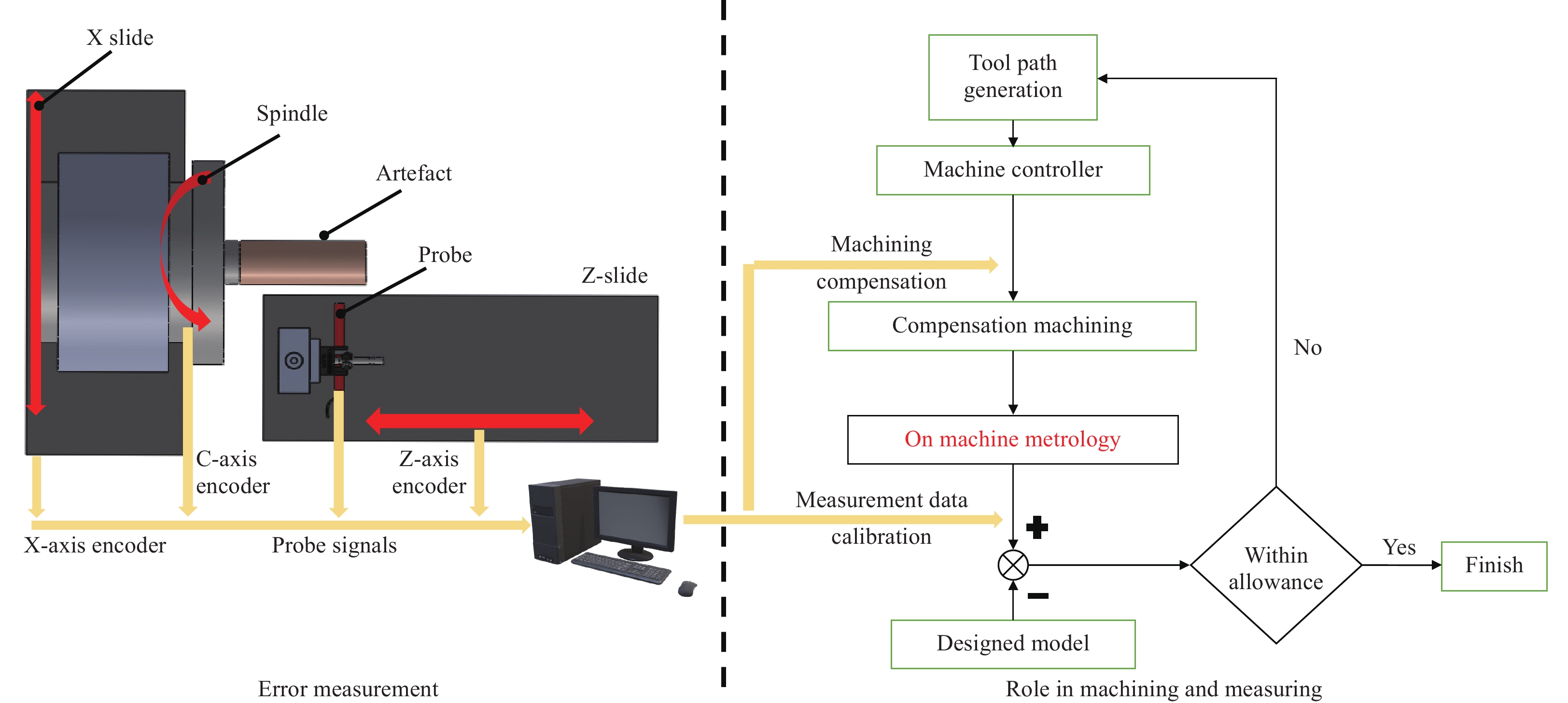
Error compensation methods are adapted to correct the cutting tool trajectories and improve the machining accuracy, and can be realised in either an on-line or off-line manner41. In offline compensation, the measured error values at discrete points are fitted into a continuous curve to modify the machining program, and thus hardware adaptation is not required. For online compensation, external PC controllers are used to insert compensation values into a machine CNC controller. Thus, machine controller signals must be accessible to users42. The error compensation can be realised by either establishing a look-up table for an open CNC controller or by modifying the NC code. It has been reported that a pre-compensation of the straightness errors EZX can achieve an improvement of 86%, 25%, and 58% in the roughness parameter
$ Ra $ for face turning, taper turning, and a spherical surface, respectively43. In addition, the differential44, 45 and iterative methods26, 31 have been proposed to improve the compensation accuracy for rotary-axis-induced errors. An inverse kinematics matrix was proposed to decompose the actual position/orientation from the workpiece coordinate system to the controlled axes46. A flowchart of the error compensation and its role in machining and measurement are schematically shown in Fig. 2. -
UPMTs are designed to generate ultra-precision freeform or micro/nano-structured surfaces, and thus the specifications of motion components (linear and rotary axes) are extremely high when compared to precision CNC machine tools4. To identify the proper methods and instruments capable of detecting motion errors of UPMTs, typical kinetic parts and their performances are briefly summarised in Table 2 as compared with those of traditional CNC machine tools. For example, the linear axis used in UPMTs is usually driven by a DC linear motor and is supported by hydrostatic bearings. Linear motors do not rely on the lead screw and hence remove the need to transform a rotary-to-linear motion. The hydrostatic bearing offers a smooth and quick activation compared to a roller-type bearing. For UPMTs, the C-axis of the work spindle is usually integrated with a brushless DC motor and air bearing, whereas the B axis is equipped with a brushless DC motor and oil hydrostatic to maximise its loading and machining capacity.
UPMTs (example: Moore Nanotech 650FGv2) Precision CNC machine tool (example: DMG NTX 2000 2nd generation turning centre) Linear axes Brushless DC linear motor, laser holographic linear scale, hydrostatic bearing
Straightness: 0.3 μm (12 μ″) over full travel of 350 mmDC motor with ball screwdriver
Roller bearing
Accuracy control for long time running
X-Y plane: 1.8 μm
X-Z plane: 1.3 μm
X-Y-Z plane: 2.2 μmRotary axes Work spindle:
Brushless DC motor, air bearing
Max. 10,000 RPM, bi-directional
Motion accuracy: axial and radial ≤ 12.5 nm (0.5 μ″)
B axis:
Brushless DC motor, oil hydrostatic bearing
Positioning accuracy ±1.0 arc-secWork spindle:
Direct drive spindle (max. 12,000 RPM)
Tool spindle accuracy: 0.532 μm
B axis:
Direct drive motor (range. 240o, min increment 0.0001o)*The specifications of Moore Nanotech 650FGv2 and DMG are collected from public information online.
https://nanotechsys.com/machines/nanotech-650fgv2-freeform-generator/
https://www.dmgmori.co.jp/en/products/machine/id=3429Table 2. Specifications of typical kinetic parts used in UPMTs and traditional CNC machine tools*
-
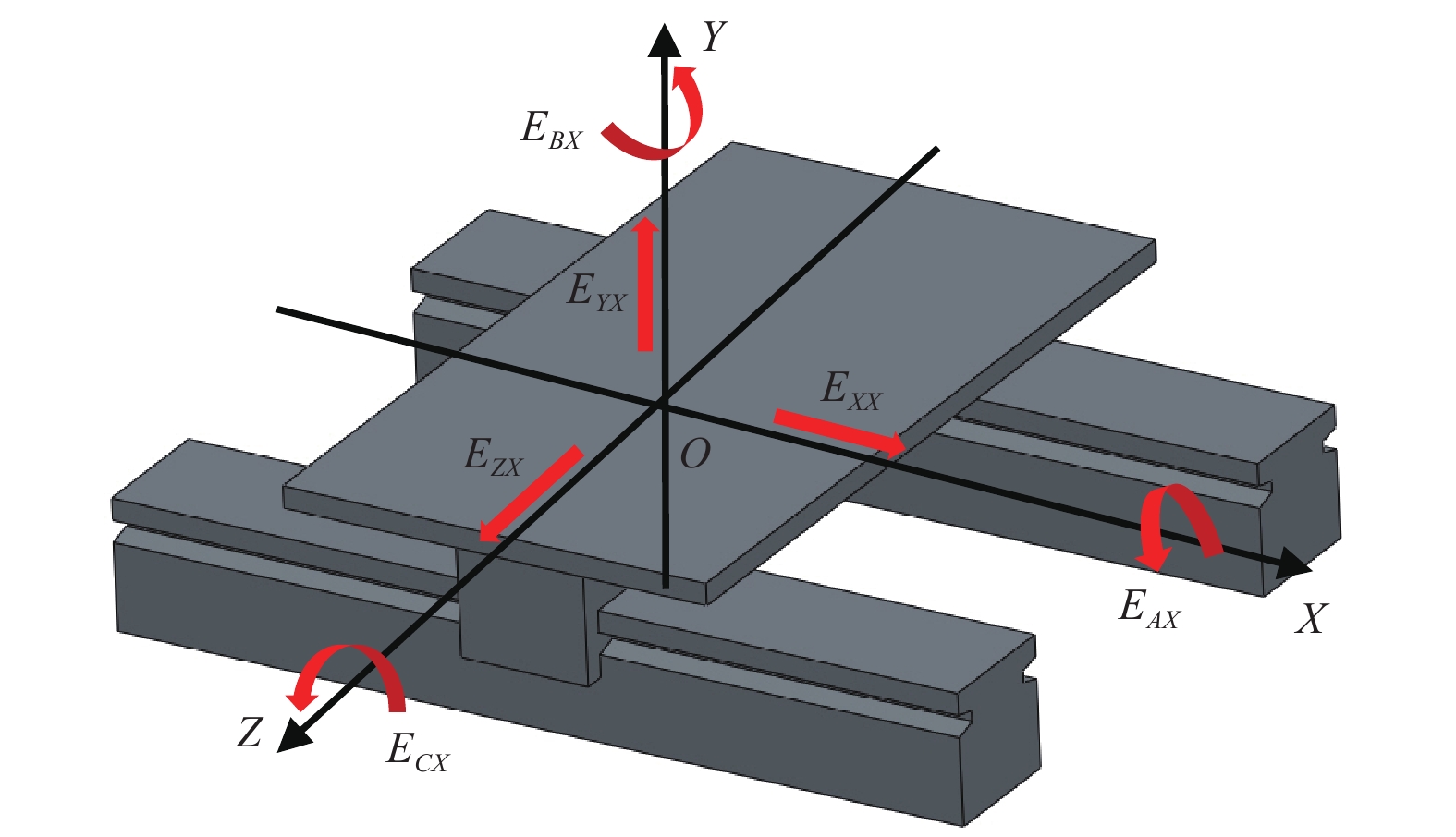
As shown in Fig. 3, the geometric error of the X slide contains one positioning error (EXX), two straightness errors (EZX and EYX), and three angular errors (roll error EAX, pitch error ECX, and yaw error EBX). For a typical 3-axis ultra-precision diamond turning machine, the straightness error of a linear axis in its critical direction can be controlled within several hundreds of nanometres over the full travel range. Therefore, high-precision sensors with nanometric repeatability are required for error detection.
The earliest studies on the linear axis error measurement of NC machine tools dates back to the 1970s. Tlusty47 proposed several techniques for testing the accuracy of NC machine tools in 1972. Hocken et al.48 measured the linear axis error for CMMs using Hewlett-Packard laser interferometers. Since then, different instruments and measuring strategies have been proposed to simplify the metrology process using magnetic ball bars49, optical straight edges50, and grating interferometer51. More recently, there has been a trend to use capacitive sensors to calibrate UPMTs owing to its nanometric measurement accuracy and high repeatability. The typical methods and their applications are summarised in Table 3.
Author Measured axis Measured error (s) Measuring methods Measuring
instrument (s)Instrument resolution Results Gao et al.52 Commercial linear air-bearing stage 150 mm Pitch, yaw, roll, straightness errors Direct measurement with two instruments Laser interferometry
Autocollimator
Capacitive probe0.05″
0.01″
10 nmRoll error: 11.8″
Pitch error: 8.7″
Yaw error: 1.6″
Horizontal straightness error: 207 nm
Vertical straightness error: 660 nmEstler50 Precision linear carriage Straightness errors Reversal method Laser interferometer 10 nm 13 nm/1 m Hwang
et al.53Hydrostatic stage 233 mm Parallelism and straightness error Reversal method
Sequential two-point methodCapacitive probe
Straightedge> 0.06 μrad Good agreement with the straightedge Campbell54 Carriage and ball bearing spindle Straightness and parallelism error Reversal method LVDT N/A 0.09 μm straightness error
2.1 μradGao et al.55 Z slide with roller bearing 126 mm Straightness error of Z slide along horizontal direction One-probe method
Two-probe methodCapacitive probe
Self-cut aluminium cylinder1 nm 620 nm
630 nmNiu et al.56 Z slide Vertically straightness error
Vertically parallelism errorThree probe method Capacitive probe
Straightedge1 nm 133 nm vertical straightness
12.1 μm vertical parallelismKong et al.43 X and Z slide with 180 mm range Straightness error of Z and X slide Standard-based directly measurement Measuring indicator N/A ~ 150 nm for X slide
~ 230 nm for Z slideTable 3. Geometric error measurement of the linear axis used in UPMTs
Gao et al.52 tested and compared the performance of different devices (e.g. a capacitive sensor, an autocollimator, and a laser interferometer) for measuring geometric errors. Two straightness errors and three rotational errors of an air-bearing stage driven by a linear motor were evaluated experimentally. For example, laser interferometry and an autocollimator were employed to measure the yaw and pitch errors, and an autocollimator and two capacitive probes were used to measure the roll error. Laser interferometry and a capacitive probe were utilised for a straightness error measurement. The straightness error measured by the capacitive sensor and laser interferometer was 209 nm (σ = 16 nm) and 205 nm (σ = 35 nm) in the horizontal direction, and 639 nm (σ = 28 nm) and 680 nm (σ = 57 nm) in the vertical direction, respectively.
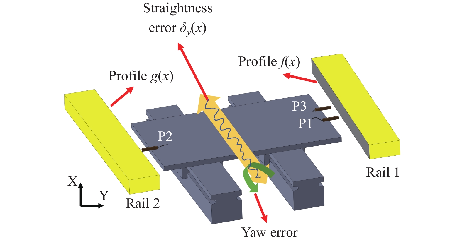
To minimise the influence of the artefact form error, a novel three-probe measurement method was proposed by Hwang et al.53. Fig. 4 shows the setup used for measuring the parallelism and horizontal straightness of an ultra-precision guideway. A pair of aluminium-coated Zerdur bars is used in this measurement method. The two capacitive probes arranged on the same side (P1 and P3) were responsible for separating the straightness error based on the reversal method, whereas the combination of probes P1 and P2 was used to identify the parallelism error. The potential measurement errors induced by the artefact were considered and minimised using the dual-probe configuration.
Indeed, the surface finish, wear, and misalignment of the artefacts inevitably induce errors in the measurement results. To avoid the effects of external artifacts, there is a trend of shifting the error measurement from the use of commercialised artefacts to self-machined parts. Campbell54 measured the straightness and parallelism error for an M18 Aspheric generator (Moore Special Tool Co.) using a reversal method. A workpiece was turned into a cylindrical shape, and a flat section of land was then cut into the back side of the log while keeping the spindle off. Therefore, the Z straightness error and out of parallelism between the spindle and Z slide can be revealed using the LVDT indicator to scan both sides.
As shown in Fig. 5, Gao et al.55 proposed an optimised dual-probe slide error measurement method using a self-cut roll. An aluminium roll was machined using a single-crystal diamond cutting tool, and a nanometric surface was finished. Two capacitive probes with a 1-nm resolution were oppositely placed on each side of the self-machined artifact to simultaneously collect data along the Z-axis direction. To eliminate the influence of the spindle error and the form error of the workpiece, the rotation angle was extracted from the encoder for accurate data matching. Therefore, the out-of-parallelism error and Z-slide straightness error can be identified through a data fitting.

Fig. 5
Error measurement setup a single probe method; and b dual-probe method55.Furthermore, the gravity-induced deformation of a self-machined roller was considered by Niu et al.56 in their multi-probe error measurement. A finite element simulation was used to predict the deflection of the artefact and the results showed that the maximum deflection was approximately 76 nm at the far end of the bar. As schematically shown in Fig. 6, three probes labelled as probes A, B, and C were distributed around the self-turned bar. The straightness error in the horizontal direction and the artefact form error can be detected and calculated from the measurement results of probes A and B. The output from probe C contained both the parallelism error between the Z slide and the spindle and the straightness error of the Z slide along the vertical direction. After the removal of the gravity deformation and the form error of the artefact, the straightness error in the vertical direction can be separated from the output of probe C. The parallelism error can be obtained using a linear fit.
-
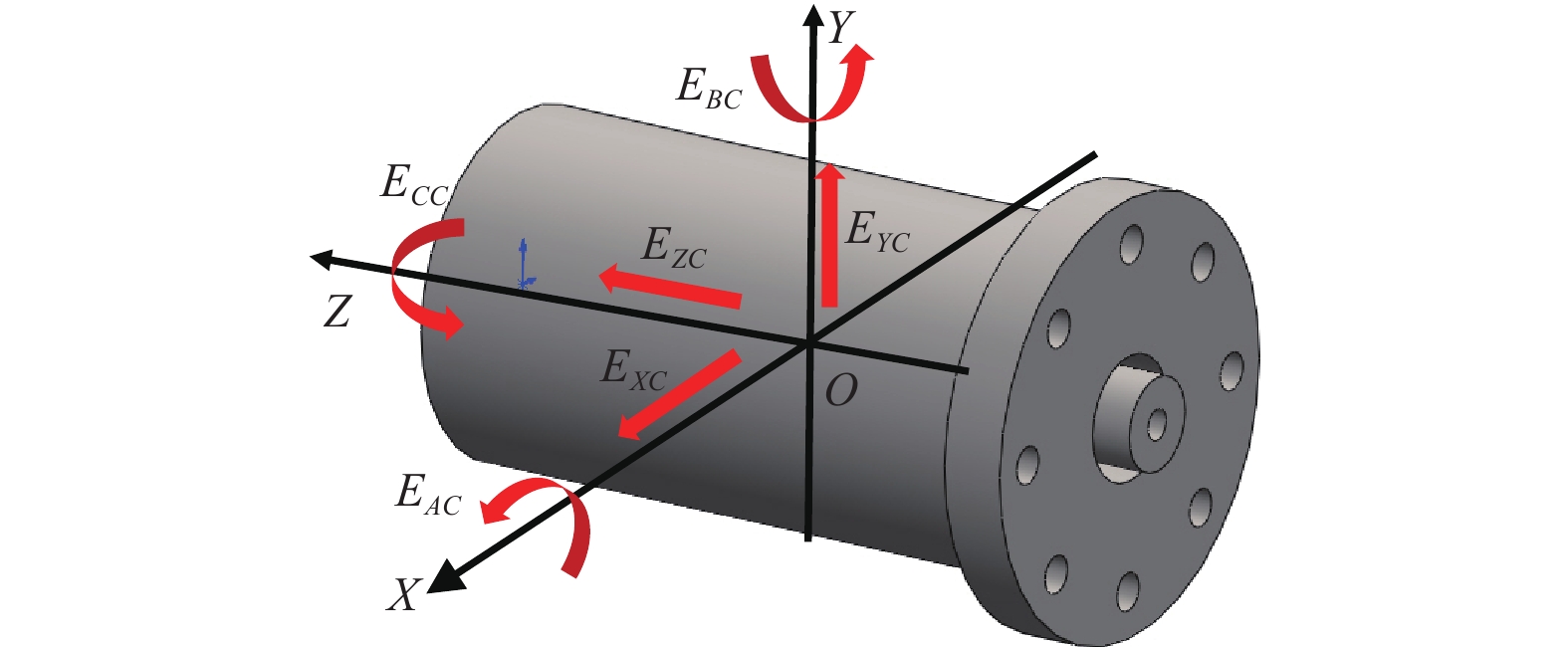
The motion error of a rotary axis includes one axial error (EZC), two radial errors (EXC and EYC), one rotary positioning error (ECC), and two tilt errors (EAC and EBC), as schematically shown in Fig. 7. The rotary positioning error was calibrated in the C-axis mode. From the frequency domain analysis, the error motion of the rotary axis can be classified into synchronous and asynchronous errors. A synchronous error occurs at integer multiples of the spindle rotation frequency and reflects the actual geometric error of the rotary axis. By contrast, an asynchronous error results from a random disturbance of environmental noise or machine tool vibration and occurs at non-integer multiples of the rotation frequency (periodic or non-periodic from the polar plot). This should be separated from the measured results.
In 1972, Donaldson57 proposed a well-known reversal technique to separate the spindle error from the test ball roundness error. Bryan et al.58, 59 further developed the basic terminology of the axis of rotation. Since then, a series of standard documents have been continuously reported on how to reduce uncertainty in the spindle metrology60, 61. The reversal method62, multi-step method63, and multi-probe method64 were adapted for a spindle motion error measurement. Typical case studies are presented in Table 4.
Author Measured axis/measured distance Measured error (s) Measuring methods Measuring
instrument (s)Instrument resolution Results Cappa
et al.69Aerostatic spindle Radial error Improved multiprobe method Capacitive probeIndexing table Φ1” spherical artefact Refer to C23-C probe < 10 nm
Angle combination (0o, 100o24’, 231o2’)Cui et al.70 Aerostatic spindle Radial error Donaldson reversal method Optical sensor
Ball artefact1.5 nm 28.49 nm Ma et al.75 Hydrostatic spindle Radial error Multiprobe method based on online finishing turning Capacitive displacement sensor 10 nm 0.3 μm for spindle
0.1 μm for artefact
Angle combination (0o, 99.84’, 202.5o)Ding et al.77 Air bearing spindle Radial and tilt errors Multiprobe method Capacitive sensor
Aluminium cylinder artefact0.3 nm Varying at different axial location Lee et al.76 Hydrostatic bearing spindle Radial/tile error Reversal method Capacitive sensor
Self-cut large roll1 nm >300 nm for spindle error Anandan
et al.78Ultra-high-speed spindle Radial error Multi-orientation method Laser Doppler vibrometry Picometer level < 5 nm for spindle errors Grejda
et al.63Air bearing spindle Radial/tilt/axial error Improved Donaldson and Estler reversal Capacitive sensors and Spherical artifact 2 mv/nm 3D display the synchronous error motion Table 4. Measurement of the geometric error of rotary axis
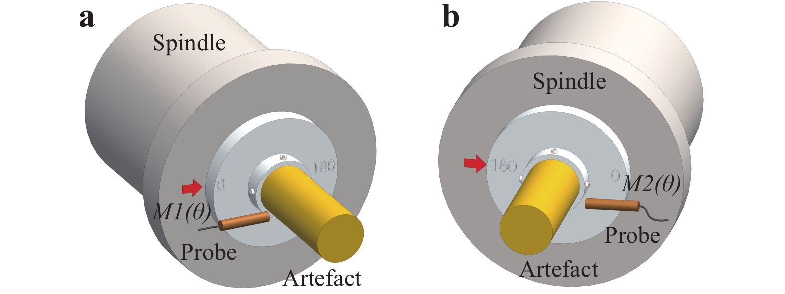
As shown in Fig. 8, the reversal method requires two rounds of measurements for each radial error, for example,
$ M1\left(\theta \right) $ and$ M2\left(\theta \right) $ , with the artefact 180° apart. The artefact form error$ A\left(\theta \right) $ and the spindle radial error in the X-direction$ X\left(\theta \right) $ are both recorded by the probe. Then both errors can be separated according to Eq. 2. The reversal method is theoretically superior to the other two methods. Several variations of reversal methods have been proposed, including the Donaldson reversal, Estler reversal, and Grejda reversal method63.$$ \left\{ {\begin{array}{*{20}{c}} {M1\left( \theta \right) = A\left( \theta \right) + X\left( \theta \right)}\\ {M2\left( \theta \right) = A\left( \theta \right) - X\left( \theta \right)} \end{array}} \right. $$ (2) The multi-step method is a popular approach for measuring the radial/axial and composite errors of rotating pick-up roundness measuring instruments, turntable roundness measuring instruments, or precision axis systems65. Many national metrology institutes, industrial calibration laboratories, and research institutes have adopted this method to quickly identify the roundness of the workpieces66. As illustrated in Fig. 9, the spindle is rotated with a uniform angle increasement
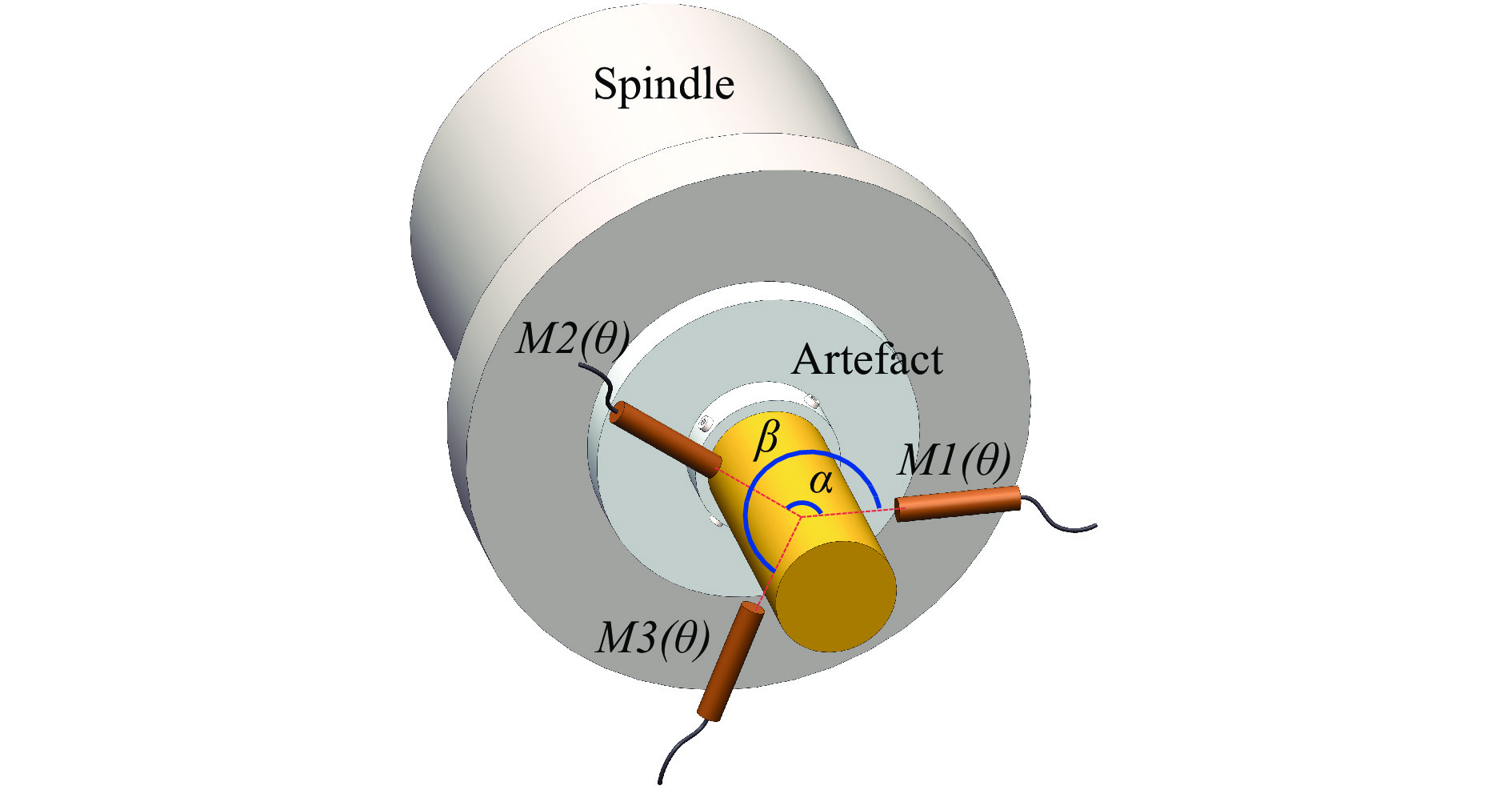
$ \theta $ , and only one probe is required to record the data. In total, N points of data are sampled as$ Mj\left(\theta \right) $ and the spindle error$ Y\left(\theta \right) $ is the average of the collected data. The workpiece roundness error$ A\left(\theta \right) $ can also be calculated according to Eq. 3. However, the number of steps should be carefully chosen to improve the separation completeness because the error motion at frequencies with integer harmonics cannot be solved. The influence of the sampling steps on the error reduction was investigated and improved through combined multistep measurements67.$$\left\{ {\begin{array}{*{20}{c}} {Y\left( \theta \right) \cong \dfrac{1}{N}\sum\nolimits_{j = 1}^N M j\left( \theta \right)}\\ {A\left( \theta \right) = Mj\left( \theta \right) - Y\left( \theta \right)} \end{array}} \right. $$ (3) The typical measurement configuration for the multi-probe method is shown in Fig. 10. Three displacement probes were located around the rotational axis with an optimised angle combination. The probes collect both the artefact form error
$ A\left(\theta \right) $ and spindle radial errors (i.e.$ X\left(\theta \right) $ and$ Y\left(\theta \right) $ ) simultaneously as presented in Eq. 4. The roundness and radial errors can be decomposed from the measurement results using a fast Fourier transform. The most critical step in using a multi-probe method is the proper selection of the angle combination to reduce the harmonics suppression. Both experimental and simulation studies have been conducted to optimise the angle combination. The results64, 68 showed that all three methods can achieve a nanometre-level error separation.$$ \left\{\begin{array}{l}M1\left(\theta \right)=A\left(\theta \right)+X\left(\theta \right)\\ M2\left(\theta \right)=A\left(\theta -\alpha \right)+X\left(\theta \right)\cos\alpha +Y\left(\theta \right)\sin\alpha \\ M3\left(\theta \right)=A\left(\theta -\beta \right)+X\left(\theta \right)\cos\beta +Y\left(\theta \right)\sin\beta \end{array}\right. $$ (4) According to the measurement site, the rotary axis error measurement can be classified into off- and on-machine measurement. The off-machine measurement requires the spindle or rotary table to be removed from the machine tool and placed on the measuring device. An off-machine measurement device usually consists of a high-precision artefact (ball or cylinder), capacitive sensor (one or two), indexing rotary table, and vibration-isolation stage. In addition, the encoder signal from the rotary axis was collected for data synchronisation. The benefits of off-machine spindle error measurement include the avoidance of extra vibration sources in the structural loop, such as motors, pumps, and driving systems.
Grejda et al.63 improved the traditional Donaldson and Estler reversal method using a separated halves chuck. The chuck can position the artefact accurately at 0°, 90°, 270°, and 360° by the pilot sphere and indexing holes. After the first measurement, the test spindle, reversal chuck, and artefact were rotated 180° using rotary table, and the artefact and the upper part of the chuck were restored for a reversal measurement. Thus, only one displacement sensor is required for this method.
Cappa et al.69 compared reversal and multi-probe methods on a precision measuring platform. A measured rotary table was placed on the platform without an external motor actuator, and a ball artifact was clamped on top of the table. The indexing table was thus responsible for setting the angle of the artifact relative to the sensor. During the measurement process, the angle location of the rotary table can be recorded by the rotary encoder, which subsequently triggers the capacitive sensor at evenly spaced angular increments. Important error sources of uncertainty, including imperfectly repositioned sensors and artefacts for each method, are theoretically expressed and simulated through a Monte Carlo method. Their results indicate that the multi-probe method has the least combined uncertainty (0.04 nm) when compared to the Donaldson reversal (uncertainty of 2.35 nm) and Grejda reversal methods (uncertainty of 0.15 nm) during practical operation.
To test the motion errors under actual machining conditions, Cui et al.70 measured the error motions of an aerostatic ultra-precision spindle (driven by a motor) on a nanometre measuring system based on the Donaldson reversal method. As shown in Fig. 11, a 3D displacement guideway was used to adjust the location of the probe. In total, 25 cycles of data were collected by the displacement sensor with a sampling frequency of 600 Hz at a rotation speed of 50 rpm. The eccentricity of the artefact was limited within 0.1 μm with a roundness of 32 nm. The results show that the mean spindle radial error is 28 nm, with σ <1 nm.
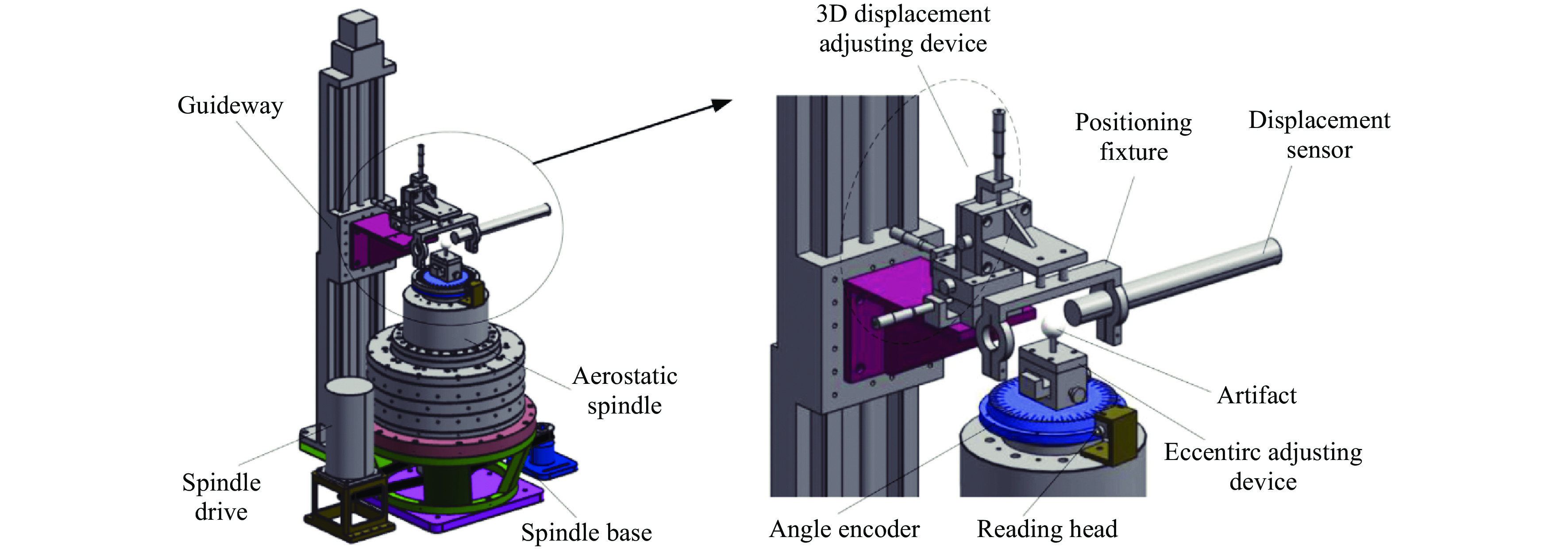
Fig. 11 Experimental platform and structure of the aerostatic spindle70.
By contrast, the on-machine measurement system estimates and separates the rotary motion errors without disassembling the rotary axis from the machine tool; thus, it offers high flexibility in practice. Commercialised embedded sensors, artefacts, and inspection modules have become available in recent years71. Chen et al.72 proposed a solution for the multivariable equation (SSME) method to overcome the harmonic suppression issue of a traditional three-probe method. The actual measurement data were decomposed as a matrix containing the roundness and radial errors in both the X- and Y-directions. The optimal angle (0o, 84o, 175o) combination was finally selected according to the rank and condition number of the coefficient matrix. As an innovation of this method, the complex Fourier transformation is replaced by solving the multivariable equation. The results indicate that the spindle radial error and the artifact roundness error were 0.239 μm (σ = 0.018 μm) and 0.337 μm (σ = 0.016 μm), respectively. Measurement uncertainty is an important part of providing a complete and reliable measurement result. Shi et al.73 brings the system theory into roundness profile measurements. The Laplace transform was utilised to analyse the input uncertainty, including three probe uncertainties and two angle uncertainties. The reported method can be an effective supplement to the ISO/IEC Guide 98-374.
To further improve the error separation accuracy, a self-cutting based spindle error measurement is proposed. Ma et al.75 turned an aluminium bar online as a reference in the rotational error measurement of a high-precision hydrostatic spindle. Three capacitive probes with a resolution of 10 nm were installed on a disk with an optimised angle combination (0o, 99.84o, 202.50o). Traditional standard measurements were also conducted to verify the proposed self-cutting method. The results indicate that the self-reference method has a higher error separation accuracy (0.3 μm for the spindle and 0.1 μm for the artefact) than the traditional standard method (0.9 μm for the spindle and 0.3 μm for the artefact).
In addition to the radial error measurement, Lee et al.76 expanded the measurement capability to tilt errors for a high-precision roll lathe. A large-scale copper-plated roll was on-machine turned and served as the measurement datum. Two capacitive probes with a 0.5 nm resolution were arranged on both sides of the roll workpiece, and the reversal measurement configuration was adapted. A fixture was designed to hold and locate the probe pair to scan along the Z-direction; thus, the tilt errors can be derived from the radial error data divided by the Z interval. Ding et al.77 also constructed an in-situ spindle error measurement platform and proposed a complementary multi-probe method for radial and tilt error measurements. A special mark was generated on the artifact to accurately identify the probe arrangement angles. To acquire stable data and avoid fluctuations during the start-up period, only the last 32 revolutions were selected to identify the spindle error as shown in Fig. 12. In addition, there have also been reports on using laser Doppler vibrometry78 and laser displacement probes79 to acquire the spindle errors.
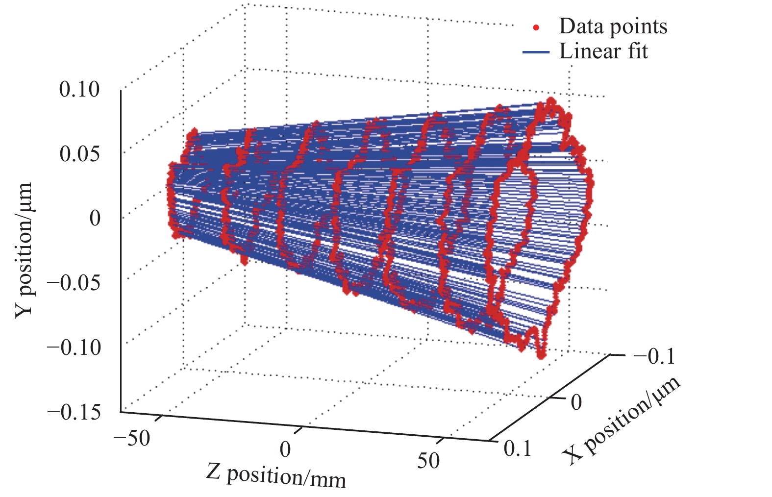
Fig. 12 Fitted trajectories of spindle rotating centre line77.
-
Owing to the complexity of the surface generation processes, it is challenging to decompose every geometric error from the measurement results. Compensation of a single linear or rotary axis has limited improvement in actual machining. To further improve the machining accuracy, indirect identification of the geometric errors through trial cutting has been developed, and the deviations of the measured topography from the designed specifications were used as the compensation value in ultra-precision machining. For example, the squareness error between the three linear axes can be identified from two machined long slots. There are also designs developed to separate the influence of kinematic errors from machined profiles80, 81. The typical methods and their applications are summarised in Table 5.
Author Machine tool Machined surface Involved geometric errors Measuring instruments Results Pezeshki
et al.803-axis milling machine Main slots and side slots Positioning, straightness and angular error along
X, Y, Z axesCMM and laser interferometer High consistency on positioning error Ibaraki
et al.815-axis milling machine Side cutting with 11 patterns 11 kinematic errors CMM and ball bar Associate the workpiece profile errors and the machine tool kinematic errors Gao et al.84 In-house developed ultra-precision 3-axis lathe Flat surface Straightness error of X slide
Spindle errorCapacitive sensor
AutocollimatorCompensation by built look-up table Yu et al.85 In-house developed ultra-precision 3-axis lathe Face turning Sliding error Stylus-based
Form tracerPre-compensation by modifying the tool path Gao et al.82 N/A Specific surface shape Simplified 11 errors Profilometer Inverse calculation the equivalent errors Tao et al.86 Nanoform X type three-axis ultra-precision lathe Plane surface Equivalent six errors on X slide Profilometer Identify three crucial geometric errors Liu et al.83 Nanotech Moore 250UPL Plane-spherical surface Equivalent five categories errors In-situ LVDT system Main machining errors are identified Table 5. Application of inverse identification method in the geometric error
Gao et al.82 delicately designed and turned a functional surface, containing a double sinusoidal surface, tapered surface, and octagon surface to identify machine tool errors in reverse. As shown in Fig. 13, the profilometer scanned result showed that the machining error between the designed and manufactured surface is 8.5 μm in peak-to-valley (PV). Liu et al.83 analysed the effects of different geometric errors on the coordinate distortion and form accuracy in ultra-precision diamond turning. A total of 24 geometric errors, including three tool alignment errors
$ Xt $ ,$ Yt $ and$ Zt $ , were merged into five groups according to the effect trend, that is the radial, circumferential, X-, Y-, and axial directions. A plane-spherical workpiece was simulated and machined to confirm the effectiveness of the proposed method. The form error PV of the cubic phase plate surfaces was measured using an on-machine LVDT probe, and after compensation, an improvement of approximately 60% in form accuracy was achieved.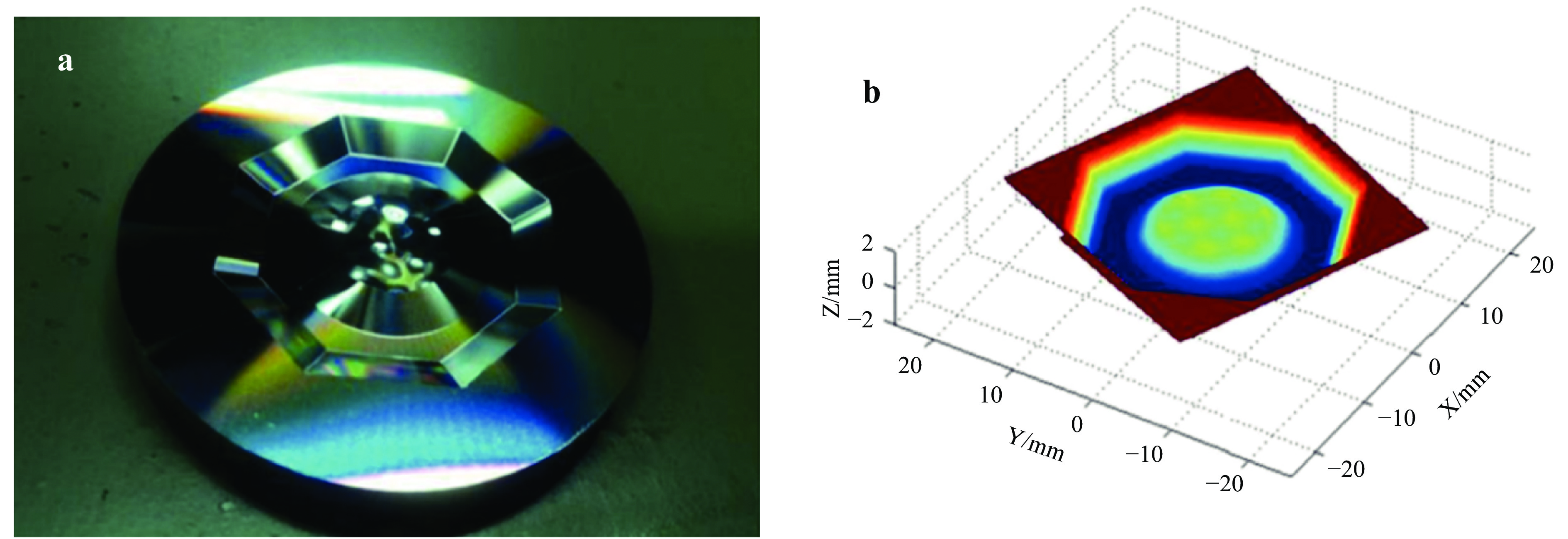
Fig. 13
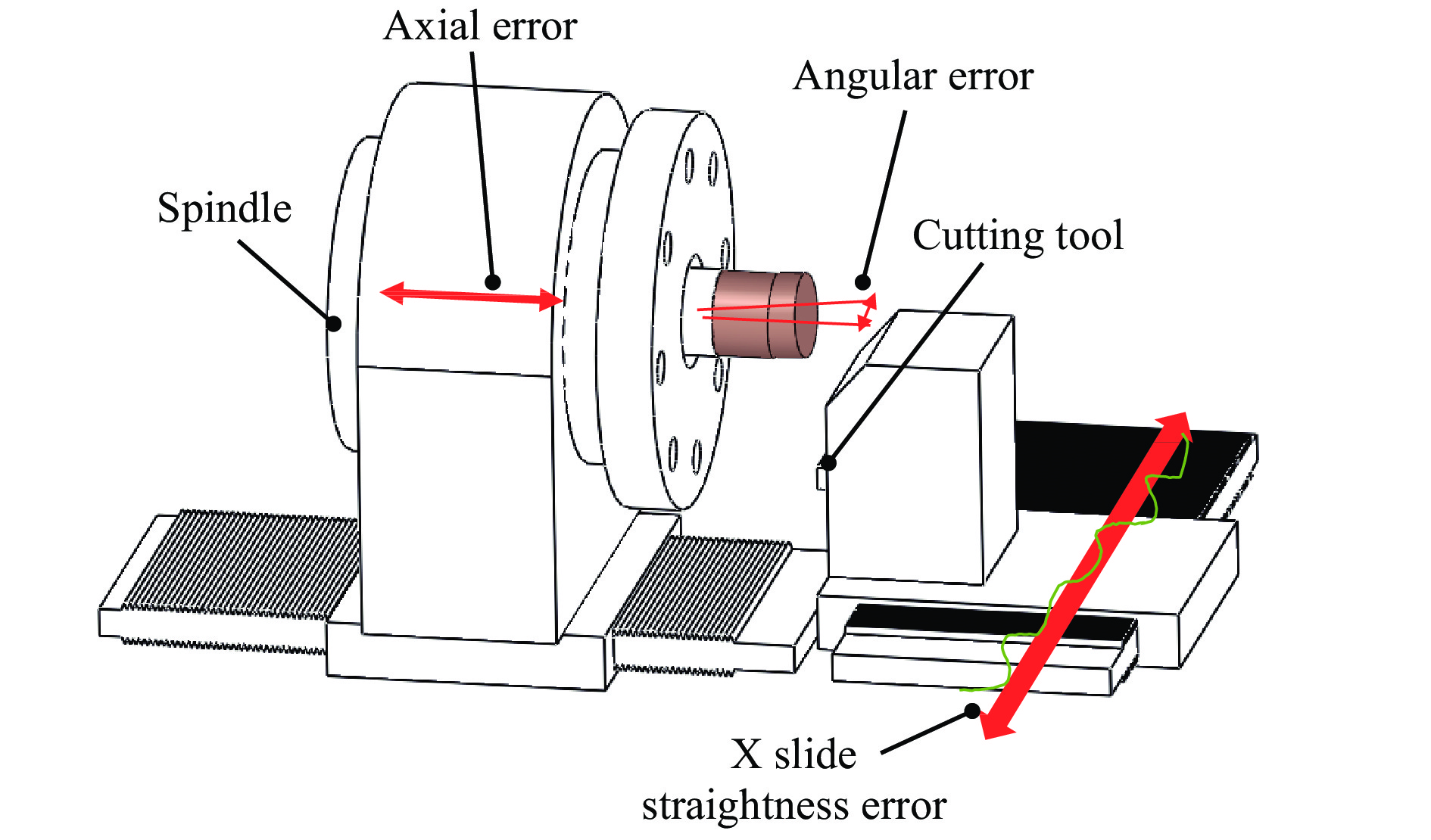
a Machined sample and b surface measurement result82.In the ultra-precision diamond turning of large sinusoidal grids, the out-of-flatness and accuracy in the Z-direction of the workpiece are difficult to satisfy because of the straightness error of the X slide and the axial error of the spindle, as schematically shown in Fig. 14. It was found that the angular and axial motion of the spindle led to two undulations per revolution error component around the circular direction84. To improve the machining accuracy, the straightness error
$ {e}_{z}\left({x}_{i}\right) $ and angular error (axial$ {e}_{f}\left({\theta }_{i}\right) $ and angular$ {e}_{a}\left({\theta }_{i}\right) $ ) were measured using capacitive sensors and an autocollimator, respectively. The compensation value was calculated using Eq. 5, and corrective machining results showed that the out-of-flatness of the machined surface was reduced to 0.12 μm.$$ \Delta z\left(i\right)={e}_{z}\left({x}_{i}\right)+{e}_{a}\left({\theta }_{i}\right){x}_{i}+{e}_{f}\left({\theta }_{i}\right) $$ (5) To minimise the effects of the squareness error on the accuracy of machined surface form, the squareness error
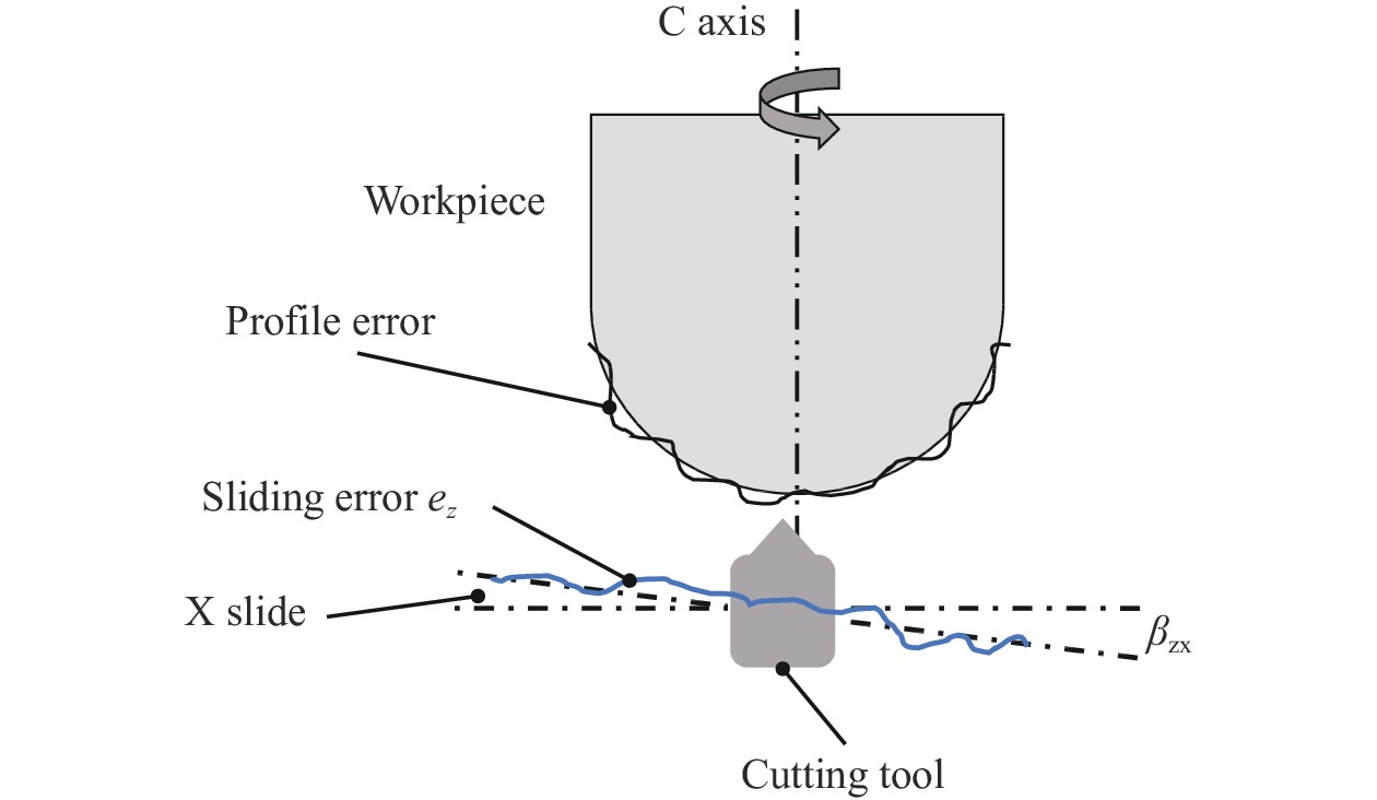
$ {\beta }_{ZX} $ of a self-developed miniature ultra-precision lathe was measured using a stylus-based tracer through a trial cutting method as schematically shown in Fig. 15. After detrending and filtering, the squareness error$ {\beta }_{ZX} $ can be extracted by fitting the slope, and the residual value indicates the straightness error$ {e}_{z}\left(x\right) $ . The tool path modification for pre-compensation machining was calculated using Eq. 6.$$ \left\{\begin{array}{l}{Z}_{cs}\left({\rho }_{0}\right)=Z\left({\rho }_{0}\right)-SInterp (X,{e}_{sz}\left(X\right),{\rho }_{0})\\ {e}_{sz}\left(X\right)={e}_{z}\left(X\right)+{\beta }_{zx}X\end{array}\right. $$ (6) Two typical micro-structured surfaces, that is, a sinusoidal wave and a micro-lens array, were machined, and the results indicated a 66.8% reduction in the profile error85.
A matrix decomposition method was recently proposed to simplify the calculation of the tool position errors86. An equivalent machining model was developed to identify the three crucial geometric errors from the surface topography of the workpiece, that is, δx, δz, and θy. Geometric errors in this model can be determined precisely through topography data sampled along a radial path on workpiece surface.
-
Owing to the extreme difficulty in detecting and decomposing error components for ultra-precision machine tools, a sensitivity analysis used in a structural reliability analysis and environmental assessment87 has been employed in recent years to recognise crucial geometric error components88. A sensitivity analysis can identify crucial input variables around a chosen point (local sensitivity analysis) or over a space (global sensitivity analysis)89. An error sensitivity analysis can be implemented once an error model is established and different algorithms have been developed to extract principal errors from the error model, such as the Morris method30, transforming differential changes90, multiplicative dimensional reduction method91, partial differentiation92, and Sobol algorithm93.
Zou et al.94 analysed the primary geometric errors for a three-axis UPMT. An error model was built based on the multi-body system theory, and the factor of each geometric error was quantified using the Sobol algorithm. The results showed that the positioning errors (δxx and δzz), angle errors (θxy, θcx and θcy), and squareness errors (βzx and βcx) were the major errors affecting the machining accuracy. Considering the difficulties in measuring and compensating the angle errors, only the positioning and squareness errors were investigated using a laser interferometer and inductance micrometer. The effectiveness of the compensation was demonstrated by turning a cylinder workpiece. Measurement results from a Talysurf PGI 1240 indicated that the form error was reduced from 1.28 to 0.65 μm.
Li et al.95 recently investigated 21 geometric errors of a Nanoform 250 Ultragrind and identified the key error components that affect the slow-tool-servo freeform machining and embedded surface measurement system. Four error components were found as primary factors in Z-direction, that is, the X-axis straightness along the Z-direction EZX, C-axis axial error EZC, C-axis tilt error EBC, and squareness error between the X- and C-axis EBOC. The reversal method using a capacitive sensor (Lion Precision C8, Minnesota, MN, USA) was applied for the error measurement, and the error map of the machine tool was plotted as shown in Fig. 16. The error map was then used to calibrate the OMSM results with an improvement in the flatness measurement accuracy of 67% in the PV.
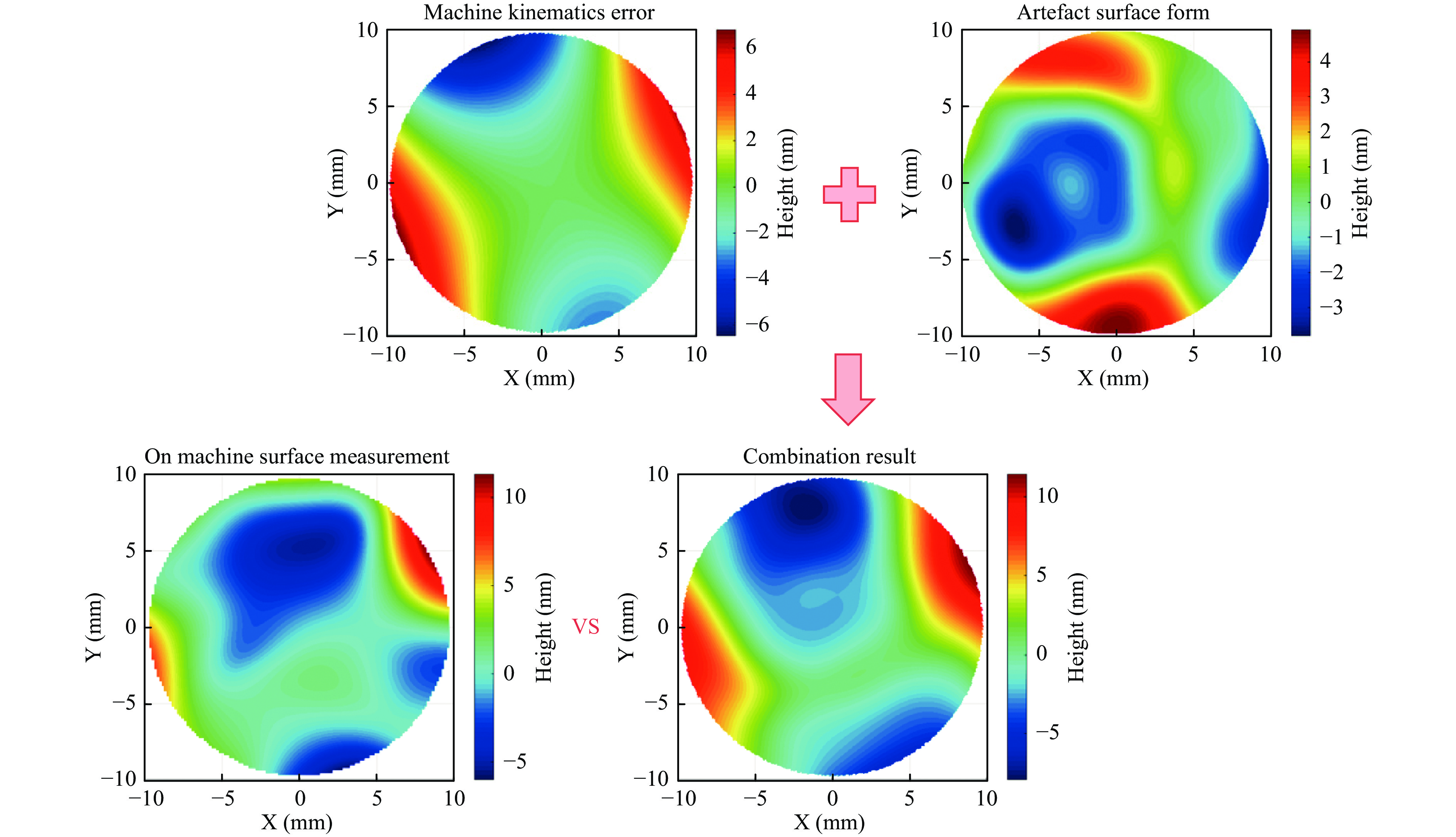
Fig. 16 A comparation between OMSM result with offline surface measurement results calibrated using machine kinematic error map95.
In optics machining, Liu et al.96 proposed an optical evaluation model to identify the primary geometric errors of the UPMT. The model was developed to link the machining with the primary optical performance parameters, that is, machining errors and wavefront aberrations. A plane-sphere structure was machined and measured using a Zygo interferometer to identify the four error components that are responsible for compensating the optical performance, that is, the tool nose radius error
$ \varDelta R $ , tool alignment error$ \varDelta x $ , XC perpendicularity error$ \varDelta \beta $ , and XZ perpendicularity$ \varDelta \alpha $ 83. An optical performance improvement model is then established and a wavefront aberration can be predicted and compensated. -
The geometric error calibration of UPMTs plays a significant role in improving the machining accuracy and ensuring the metrology confidence of OMSMs. The geometric error calibration of UPMTs follows the general routine of error modelling, error measurement, and compensation. Several error modelling methods have been developed based on the homogenous transformation matrix method, differential motion matrix method and screw theory. The reversal method and the multi-probe method with high-precision capacitive sensors are widely applied in error measurements for linear and rotary axes, respectively. Compared to externally mounted artefacts, the use of a self-turned reference bar has shown that it is beneficial to minimise the effects of the misalignment and wear of the artefacts on the measurement results. Owing to the complexity of error modelling and the high requirements of the measurement sensor performance, it remains challenging to detect and decompose each motion error of the UPMTs. Trial cutting and geometric error sensitivity analysis-based methods have received increasing interest in practice for major error extraction and compensation.
Through this literature review, the following challenges and considerations can be made:
● The error model method widely used in traditional machine tools can expose the error magnitude along each direction quantitatively but has limitations when applied to the error compensation of UPMTs. The compensable errors for a machine tool depend on the number of controllable motion axes. For example, the classic XZC-type ultra-precision diamond turning machine can theoretically only compensate two positioning errors and one rotary error. How can current error modelling methods be developed to better fit the motion error prediction and compensation of UPMTs?
● New technical challenges have been raised regarding the development of measurement instrument and methods suitable for on-machine UPMT error calibration. The measured error values of UPMTs are usually at the submicron or even nanometre scale, and it is extremely difficult to detect and decompose each error component from the coupled error measurement results. There is also a real concern regarding the reproducibility of using capacitive/optical sensors because the data synchronisation of the measurement probe with the axis location is crucial to guaranteeing the sampling accuracy. Is such a method possible through an embedded sensor net?
● How can ultra-precision machining processes be effectively compensated (e.g. turning, milling, or grinding)? The difficulties in decomposing every geometric error from the measurement results significantly hinder the development of effective error compensation methods for improving the machining accuracy. The limited static or dynamic stiffness loop also limits the effectiveness of any kinematic error compensation algorithm. Can this be achieved through a closed-loop machining measuring iteration process?
● The trial cutting and measurement of a specially designed topography provides a promising method for inversely identifying and compensating synthetic errors to a certain level in practice. An error sensitivity analysis and the design of more elaborate surfaces to expose more error components by trial cutting would be an interesting future topic in this area.
-
The authors gratefully acknowledge contributions received from colleagues, particularly Dr. Christian Young, for his suggestions and help in proofreading the full paper. The authors would like to acknowledge the funding support from the UK’s EPSRC Future Metrology Hub (Ref: EP/P006930/1), the UK’s STFC Innovation Partnership Scheme (STFC-IPS) project under grant agreement No. ST/V001280/1, the European Union’s Horizon 2020 research and innovation programme under grant agreement No. 767589, and the China Scholarship Council (CSC).
Review of geometric error measurement and compensation techniques of ultra-precision machine tools
- Light: Advanced Manufacturing 2, Article number: (2021)
- Received: 31 July 2020
- Revised: 05 February 2021
- Accepted: 09 February 2021 Published online: 08 May 2021
doi: https://doi.org/10.37188/lam.2021.014
Abstract: Inevitable machine motion errors change the cutting tool trajectory and degrade the machined surface quality. Compared to the mature error measurement technologies developed for traditional precision CNC machine tools, the increasing use of ultra-precision machine tools (UPMTs) has shown some distinctive characteristics in error modelling, measurement, and compensation. This paper attempts to summarise state-of-the-art research in the calibration of geometric errors of UPMTs. A general routine for a UPMT error calibration is proposed in this literature review. Various error modelling methods, instruments, and measurement methods applicable to the geometric error measurement of both the linear and rotary axes are discussed using typical case studies. With respect to these achievements, there is a real concern regarding the reproducibility of measurement sensors used for the calibration of UPMTs and it remains challenging to decompose the volumetric motion error of UPMTs. Owing to the high flexibility in practice, trial cutting and a sensitivity analysis-based error measurement and compensation provide a promising solution to achieve a fast UPMT calibration.
Research Summary
Calibration: Realizing the true potential of ultra-precision machines
The ultra-precision machine tools is the essential equipment to produce fantastic functional surfaces and complex parts with extremely high form accuracy and mirror surface finish. Performance evaluation from time to time is the key to diagnose any issues of machines. Dr Zhen Tong etc. from the UK's EPSRC Future Metrology Hub at University of Huddersfield now reviews state-of-the-art research work on geometric errors measurement and compensation techniques of advanced ultra-precision machine tools. A general routine of calibration is proposed, and special attention is given to the historical development of measurement instruments and methods used for both linear and rotary axes calibrations. New trends on developing fast machine calibration methods are discussed, and technical challenges are raised regarding the robustness of measurement instruments and effectiveness of error compensation methods.
Rights and permissions
Open Access This article is licensed under a Creative Commons Attribution 4.0 International License, which permits use, sharing, adaptation, distribution and reproduction in any medium or format, as long as you give appropriate credit to the original author(s) and the source, provide a link to the Creative Commons license, and indicate if changes were made. The images or other third party material in this article are included in the article′s Creative Commons license, unless indicated otherwise in a credit line to the material. If material is not included in the article′s Creative Commons license and your intended use is not permitted by statutory regulation or exceeds the permitted use, you will need to obtain permission directly from the copyright holder. To view a copy of this license, visit http://creativecommons.org/licenses/by/4.0/.
















 DownLoad: