


-
The motivation of this work stems from an automotive application, where an inline measurement system is required to enable the collection of topographic data of the car body throughout its entire production cycle. Therefore, the system should be capable of delivering data starting from the raw diffuse scattering metal sheets to the colored and polished varnish surfaces of the final car body. Important measures of a car’s production quality are the size and depth of the gap between two adjacent car body parts. The same system should preferably be employed during the production cycle to enable the comparability and traceability of any manufacturing errors. The field of view should be at least 10 × 10 mm2 with an axial measurement range of 2 mm, a lateral and axial resolution of 20 µm, and an acquisition time of less than 50 ms.
Therefore, a high-speed topographic measurement on non-cooperative surfaces (specular reflective and/or diffuse reflective) needs to be performed, and represents a major challenge in optical metrology. There are surface metrology techniques that can cope with these types of surfaces, such as white light interference microscopy (WLI), confocal microscopy (CM), and conoscopic holography (CH). However, the measurement is very time-consuming, and ranges from a few seconds to minutes, depending on the field of view and resolution. This is because WLI and CM are very detailed, revealing all surface parameters such as the roughness, waviness, and shape. Furthermore, they can be applied to investigate volume scattering samples because they offer optical sectioning1. By contrast, CH represents a polarization optical common path-point interferometer2, and requires scanning in both lateral dimensions. Therefore, it is based on a more complex setup and cannot satisfy the high demand imposed on the data rate of more than 5 million data points per second. Structured illumination, such as fringe projection, can reveal the shape based on a single imaging frame, but it can only be applied to rough scattering surfaces. Moreover, a projection device, which is often implemented via a spatial light modulator and a certain angle between the projection and observation directions, is necessary to enable triangulation. It is therefore not only limited by the type of surface, but also suffers from shadowing artefacts and cannot be used to investigate deep holes or steep surfaces, which is possible with the aforementioned online systems WLI, CM, and CH.
Therefore, there remains the need for a system that can measure the topography of non-cooperative surfaces at high speed.
One imaging technique that can be employed for such a purpose is dual-wavelength holography (DWH)3, which can simultaneously be applied to rough scattering4 and specular reflective surfaces3. The measurement system does not rely on triangulation, and can therefore be applied to recover three-dimensional (3D) depth data from deep holes, steep surfaces, or similar geometrical features.
The digital hologram is acquired as an interferometric superposition of the reference wave and object wave on charge-coupled device (CCD) or complementary metal-oxide semiconductor (CMOS) detectors.
Depending on the recording scheme, i.e., on-axis or off-axis, the phase in the hologram plane is recovered via phase stepping/shifting or filtering in the Fourier domain. A detailed discussion of the recording geometries as well as their advantages and disadvantages can be found in Refs.5−7. If a defocused hologram is recorded, reconstruction algorithms8−10 can be applied to obtain the phase distribution in the object plane. However, in image-plane holography, the digital sensor is positioned in the image plane. Therefore, no refocusing algorithms need to be applied. The phase information in the object plane provides important information about the topography of the object, and is represented as a wrapped phase map with phase values ranging between -π and π. Therefore, the unambiguous evaluation of the phase is limited to a phase difference of less than 2π between neighboring reconstructed object points, which corresponds to a path length change of half a wavelength. Hence, the application of conventional holographic interferometry imposes certain constraints, which hinders the evaluation of strongly curved, inclined surfaces or surface-steps that exceed half the wavelength. This problem can be solved by employing the dual-wavelength method. This method is based on holographic recording and reconstruction at two different wavelengths, λ1 and λ2. The phase difference that is calculated from the two wavelength reconstructions can be associated with the synthetic wavelength λsyn:
$$ {\lambda }_{syn}=\frac{{\lambda }_{1}{ \cdot \lambda }_{2}}{\left|{\lambda }_{1}{-\lambda }_{2}\right|}=\frac{{\lambda }_{1}{ \cdot (\lambda }_{1}+\Delta \lambda)}{\Delta \lambda } $$ (1) which is much larger than that of the individual wavelengths employed. The resulting phase difference map Δφ consists of contour lines (fringes) with 2π-steps. The theory of fringe formation has been described in more detail in Refs. 11 and 12.
The application of the dual-wavelength method is not only limited to surface metrology but can also be applied for defect detection/evaluation or for comparison of shape differences13−19.
The topography:
$$ T=\frac{{\Delta }\varphi }{4\pi }{\lambda }_{syn} $$ (2) can be calculated from the synthetic wavelength and the phase difference Δφ between the wavelength-corresponding digital holographic reconstructions, in which both the illumination and observation vectors are perpendicularly aligned to the object and sensor surface.
The phase information required to recover a shape that may comprise rapid height jumps within the mm or even cm range can be recovered from a single digital hologram20. The imaging speed is limited only by the acquisition speed of the two-dimensional (2D) digital sensor and the power of the light source to supply a sufficiently large amount of scattered and reflected light to enable recordings beyond the noise threshold of the sensor.
Moreover, DWH offers a flexible and lightweight setup, without the need of imaging lenses. This is enabled by the recovery of the complex wavefront in the sensor plane (amplitude and phase) and the application of wave propagation algorithms to refocus from the sensor to the object plane, as discussed in Ref. 21.
However, the measurement uncertainty of the DWH depends on the stability of the previously measured individual wavelengths during the calibration process. To better understand the measurement error introduced by a change in the wavelength difference, we differentiated Eq. 1 with respect to the wavelength difference
$ \Delta {\bf{\lambda }} $ , which results in$$ \frac{\partial {\lambda }_{syn}}{\partial \Delta {\boldsymbol{\lambda }}}=\frac{{\mathrm{\lambda }}_{1}^{2}}{{\Delta {\boldsymbol{\lambda }}}^{2}} $$ (3) For a desired measurement uncertainty of 1/100 of the measurement range T, the standard deviation of the wavelength difference is
$$ \partial \Delta \lambda =\frac{\Delta \lambda { \cdot (\lambda }_{1}+\Delta \lambda)}{{100 \cdot \lambda }_{1}} $$ (4) Plotting the standard deviation of the wavelength difference against the synthetic wavelength results in the curve shown in Fig. 1, with the first wavelength
$ {\lambda }_{1} $ = 850 nm. Hence, for a measurement uncertainty of 1/100 of the measurement range of, for instance, 2 mm, the standard deviation of the wavelength difference should not exceed 2 pm. This imposes a high demand on the stability of the light source.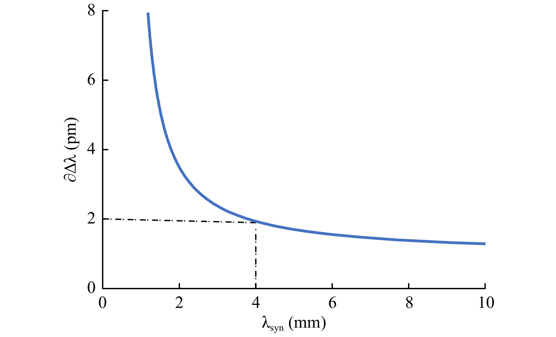
Fig. 1 Synthetic wavelength over the standard deviation of the wavelength difference.
Different methods have been developed to address this issue. In Ref. 22, a white light-emitting diode (LED), which represents a broadband spectral light source, was employed. More than 1000 holograms were recorded by shifting the piezo in the reference path. By applying the Fourier transform along the z-axis of the recorded stack of holograms, the spectral signal could be recovered. The spectrally resolved holograms were displayed in the
$ k $ -space, which corresponds to$ {1}/{\lambda } $ , with$ \lambda $ being the corresponding wavelength. The equal spacing in$ k $ has an advantage in that phase map pairs with the same difference in k generate the same synthetic wavelength. This effect was used, and 34 equally$ k $ -spaced phase difference maps were averaged to obtain a speckle noise-minimized reconstruction. Moreover, when considering the entire complex spectral information, a volume-scattering sample could be investigated, and an optical section that was focused on different axial slices could be applied in the same manner as the previously mentioned WLI. In addition to the spectral self-calibrating and noise minimizing characteristics, the system has a low acquisition speed, which is in the range of several minutes, and which is therefore not applicable for our task.In Ref. 23, a conventional line spectrometer was employed to simultaneously record the individual wavelengths during the experiments. This approach is feasible for short synthetic wavelengths within the µm range, but fails at longer synthetic wavelengths in the millimeter range or beyond, which requires a spectral resolution in the pm or sub-pm regime to ensure a reasonable measurement uncertainty.
In Ref. 24, the detector was employed as a spectrometer using a reflection grating. However, this approach suffers from a limited applicable range of the synthetic wavelength owing to the limited spectral resolution. Moreover, only one point is measured, which requires lateral scanning to obtain 3D information of the entire object.
Another system relies on the application of reference objects of a previously known height or phase delay, which is sequentially moved into the path25, and hence enables the recovery of the synthetic wavelength from the phase difference map. However, this approach is based on the assumption that the environmental conditions and the wavelength of the employed light source(s) remain unchanged for the subsequent recording of the holograms with two different wavelengths. Furthermore, the reference device needs to be moved in and out of the optical path, which requires additional stages, and hence, increases the complexity of the setup.
-
The aforementioned issue that impedes the determination of the synthetic wavelength during the measurement is addressed via the application of a highly stabilized coherent light source. We employed a vertical-cavity surface-emitting laser (VCSEL) light source for this task, and although it has a diameter of only 50 µm and a similar height, it has a coherence length of up to 50 cm. Moreover, the radiation profile that is emitted is circularly symmetric at all axial distances from the source, which when compared to the predominantly elliptical radiation profile of edge-emitting devices, makes them perfectly suited for single-mode fiber launching with high coupling efficiency.
Compared to conventional coherent light sources such as He-Ne lasers or edge-emitting laser diodes, VCSELs have a very short laser cavity. Therefore, within a few µs after changing the current, the wavelength is already stabilized, which enables the generation of multiple synthetic wavelengths within a short sequence. Moreover, the temporal coherence covers a few tens of centimeters, which outperforms the typical coherence length of an edge-emitting laser (only a few millimeters) and is comparable to that of He-Ne lasers.
Thermally caused wavelength drifts are very small in comparison to edge-emitting lasers (typically 0.25 nm·K−1 (Ref. 26).
In addition, the wavelength can be tuned by a few nm by changing either the current (0.5 nm·mA−1) or the temperature (0.06 nm·K−1).
Therefore, they cannot be highly wavelength stabilized. Fine adjustment of the wavelength by the application of a precise adjustable current source enables the adaption of the synthetic wavelengths to the object of interest or improvement of the measurement uncertainty using multiple synthetic wavelengths.
The generation of the spectrally highly stabilized dual-wavelength VCSEL source is presented in the Materials and Methods section.
To highlight not only the speed advantage, but also to demonstrate that the results do not depend on the surface roughness, material, and color, the single-shot dual-wavelength method was applied to specular reflective surfaces, diffuse reflective surfaces, and industrial surfaces with different colors. The fiber-based setup is shown in Fig. 2c, and holograms that are based on an off-axis single-shot image plane holographic arrangement are recorded. More details about the setup are discussed in the Methods section. The field of view covered an area of 10 × 10 mm2. The ILA CMOS image sensor was used, which offers 2000 × 2000 pixels with a pixel size of 6.5 µm and a 16-bit analog-to-digital converter (ADC) with a low readout noise of 2.2 electrons. In this manner, it is possible to tolerate the slightly increased output image noise due to the simultaneous recording of two holograms in a single acquisition, as reported in Ref. 27. After recording the hologram, the wavelength corresponding to the information content must be extracted.
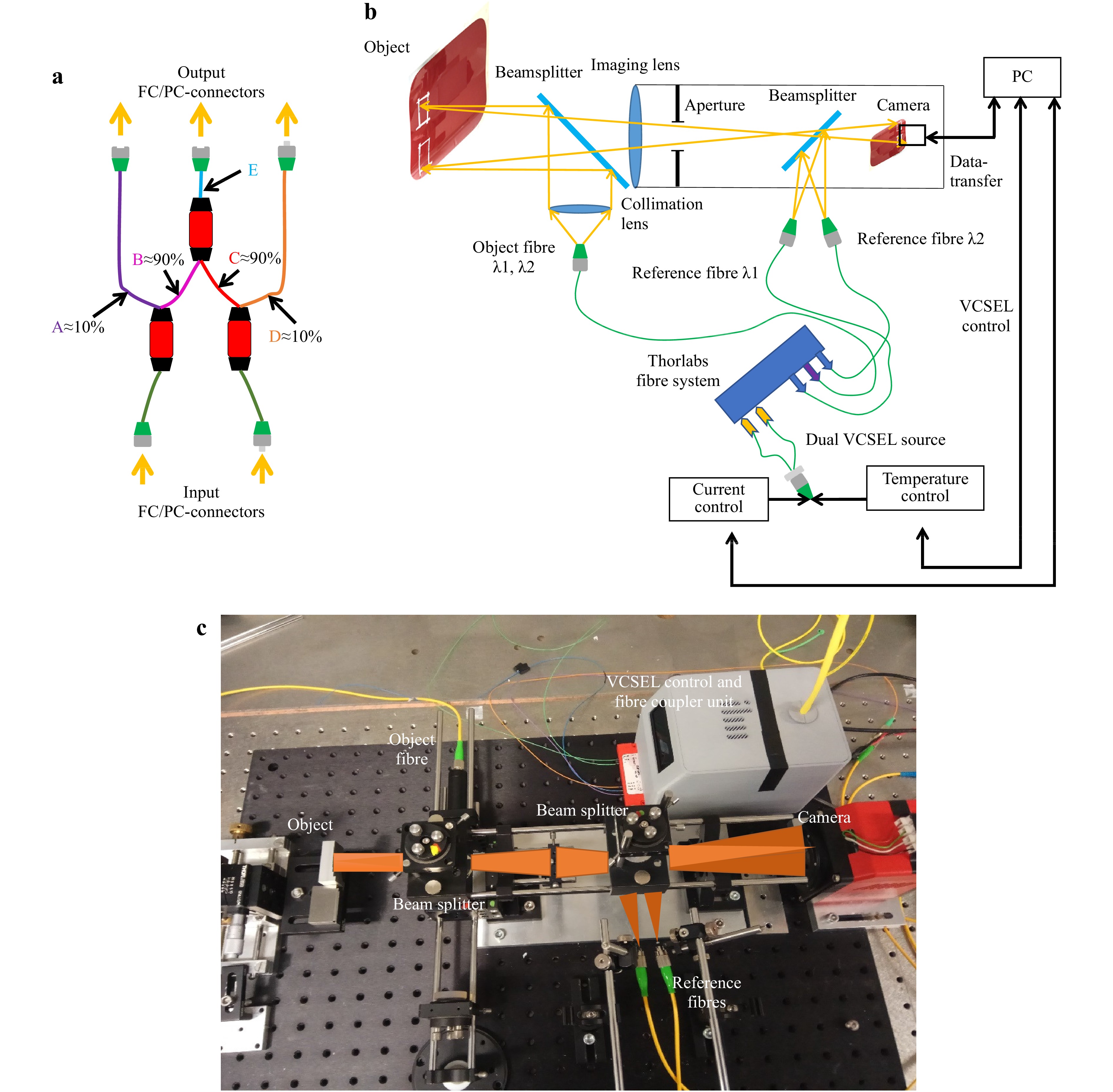
Fig. 2 Experimental setup
a Schematic presentation of ILM designed fibre system, where fibres A and B correspond to the reference- and object-fibre of the first VCSEL, D and C the reference- and object fibres of the second VCSEL, E the combined object-fibers from object-fibers of the first VCSEL B and second VCSEL C, b schematic implemented setup, c experimental setup with a step object of sequentially reduced step size.The reconstruction of the complex amplitude was accomplished by filtering in the Fourier plane9 (see Fig. 3). Owing to the different inclination angles of the two reference beams, which correspond to the two different wavelengths, two differently oriented carrier frequencies having almost the same amplitude were incoherently superimposed in a single acquired hologram. Using a 2D Fourier transformation, the complex object waves for the two different wavelengths can be separated in the Fourier space. Thus, the corresponding information can be filtered and zero-padded to result in the same number of pixels. The complex object wave in the image plane is obtained by applying an inverse Fourier transform.
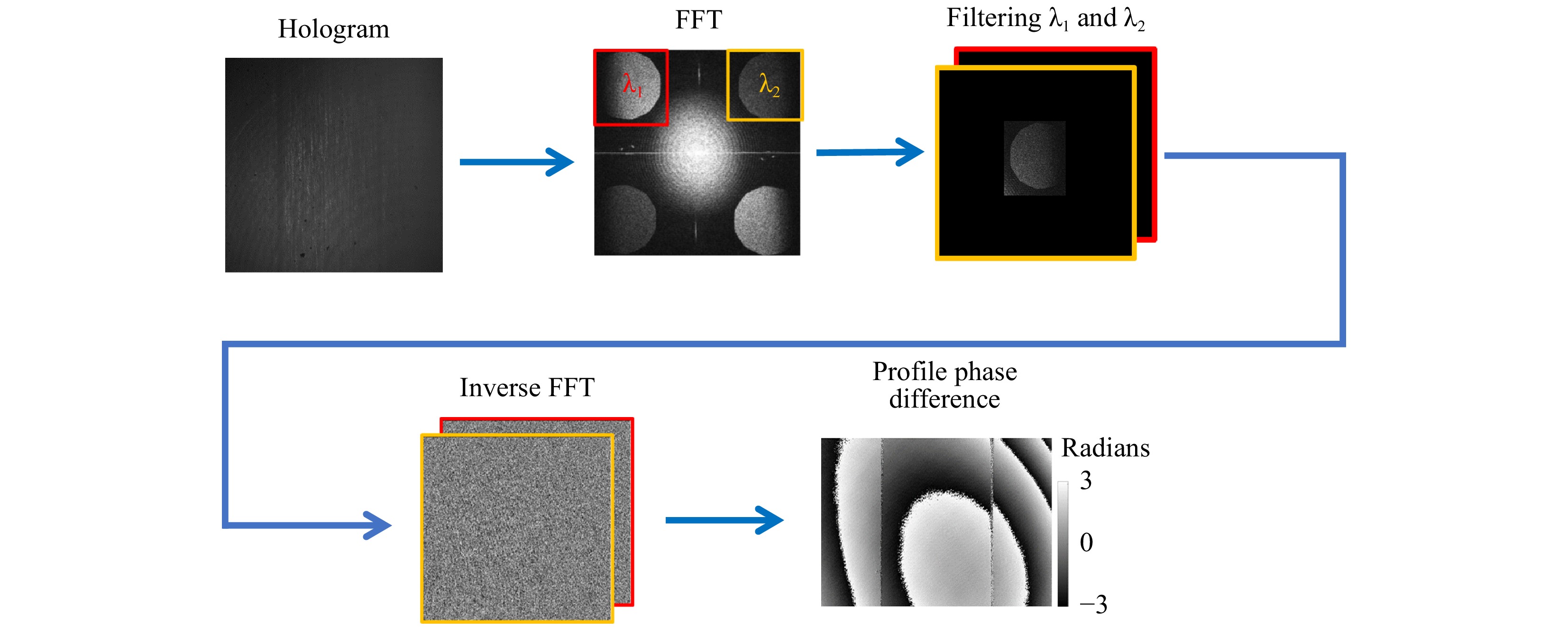
Fig. 3 Phase difference and topography reconstruction algorithm.
To compensate for the residual phase, a reference hologram was recorded, as shown in Fig. 3. For the reference hologram, a flat mirror was positioned at the same distance from the sensor at which the object is located. The use of the same reconstruction procedure shown in Fig. 3 results in a residual phase map, which accounts for the phase difference introduced by the imaging lens and the two spherical reference wavefronts that are incident on the sensors at different angles. The reference wavefront is intrinsic to the system for the same choice of synthetic wavelength, and therefore, only has to be recorded once if the synthetic wavelength is not changed. Even if the synthetic wavelength changes, this reference phase map may still be used. A change in the synthetic wavelength results in a different scaling of the residual phase with respect to the synthetic wavelength; with a shortened synthetic wavelength, the residual phase possesses more 2π phase wraps, but the overall shape remains unchanged, as discussed in Ref. 28. After subtraction with the reference phase map, the phase of the object under investigation that corresponds to the synthetic wavelengths becomes clearly visible and free from major disturbances (see Fig. 4).
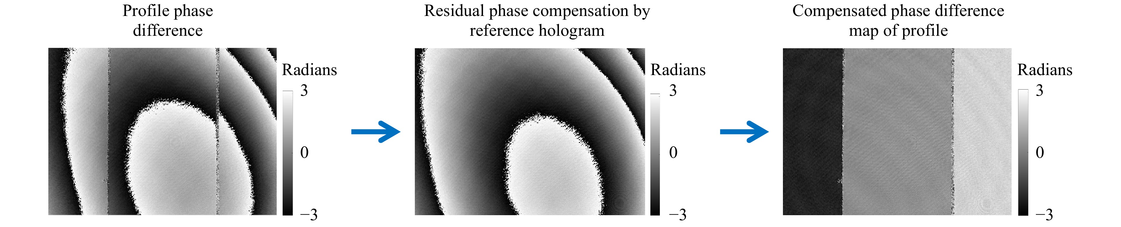
Fig. 4 Residual phase compensation to obtain the undisturbed topography map of the sample under investigation.
-
To evaluate the measurement uncertainty and sensitivity of our proposed device, specular reflective surfaces were chosen, which do not introduce speckle noise and therefore result in a high-quality difference phase map. We used reflective gauge blocks manufactured according to DIN EN ISO 3650, which offers a thickness manufacturing uncertainty of ± 0.4 µm. The synthetic wavelength that was used was 8.92 mm, and the corresponding 2D height distributions for the two-gauge blocks with heights of 2 mm and 1 mm are shown in Figs. 5a−c. The field of view was covered by both gauge blocks, resulting in a total height of 3 mm. The exposure time used to evaluate an area of 10 × 10 mm2 was 5 ms. Thus, the minimum required axial measurement range of 2 mm and the measurement time could even be exceeded.
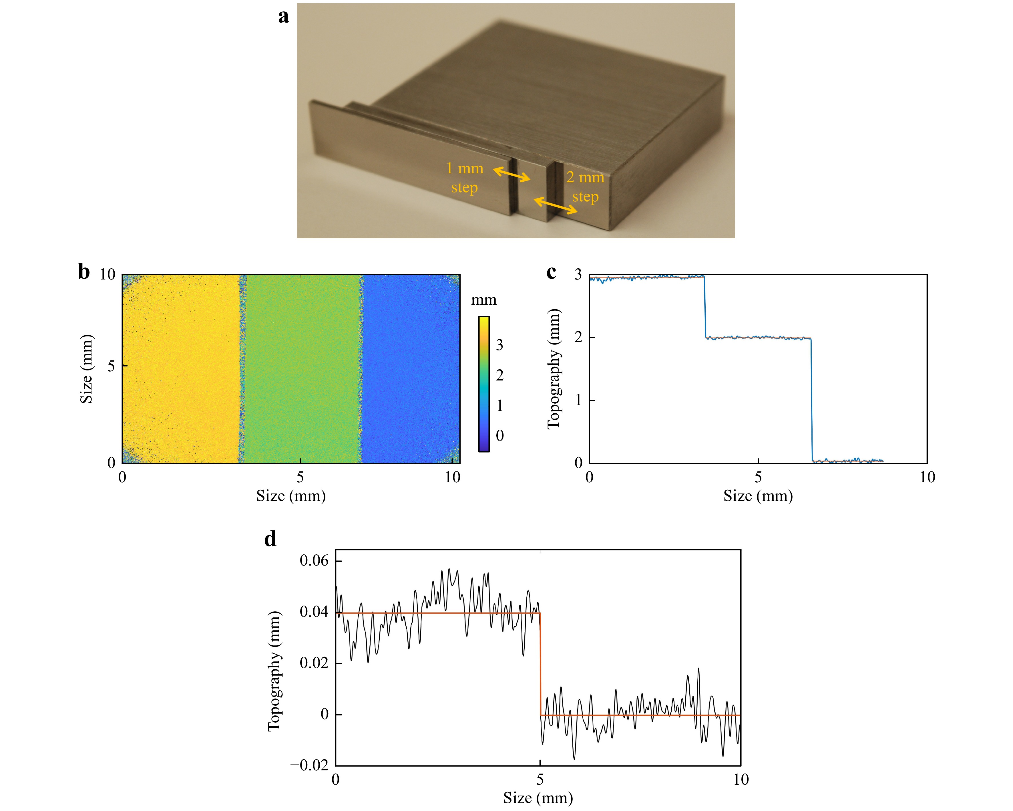
Fig. 5 Measurement results of specular reflective sample
a specular reflective height gauges, b topography map, c topography cross-section plot, d topography cross-section for 40-µm step height.To evaluate the height sensitivity of our proposed device and the measurement uncertainty, blocks with two different gauges and with a height difference of 40 µm were chosen, while maintaining the same synthetic wavelength of 8.92 mm. Fig. 5d shows the topography profile. Because the step-profile is clearly visible, the measurement uncertainty is 9.8 µm, which according to Ref. 29 is obtained from the square root of the sum of the squared standard deviations of the higher (σ = 7.8 µm) and lower surfaces (σ = 6.0 µm); corresponds to 0.22% of the measurement range of 4.46 mm (half the synthetic wavelength). For smaller step heights such as 20 µm, a clear distinction was no longer possible.
-
To further prove the versatility of the dual-wavelength method at recovering the topography of any object with respect to the surface quality, an in-house computer numerical control (CNC) milled diffusely scattering object was selected. The sample has eight steps with varying heights of 2 mm, 1 mm, 400 µm, 200 µm, 100 µm, 40 µm, 20 µm, and 10 µm, as shown in Fig. 6. The diffuse reflective step sample was produced with a manufacturing accuracy of
$ \pm $ 15 µm provided by the CNC machine.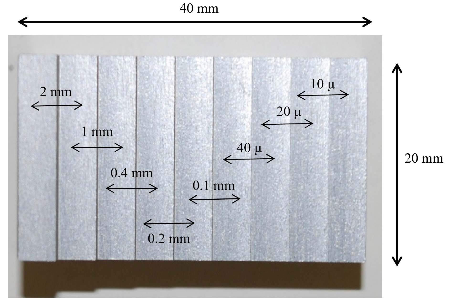
Fig. 6 Diffuse reflective step sample.
Because the rough surface scatters light more strongly than the specular surface used in our previous investigation, the exposure time had to be increased to 35 ms. In Fig. 7, the topography map and cross-section plots for the 2-mm and 1-mm steps are represented. The heights measured with our system are 1.96 mm for the manufactured 2-mm step and 0.96 mm for the 1-mm step. The quality difference between the specular reflective and diffuse reflective objects is based on a different degree of speckle noise, which is obviously higher for the second one, owing to the increased roughness of the surface.
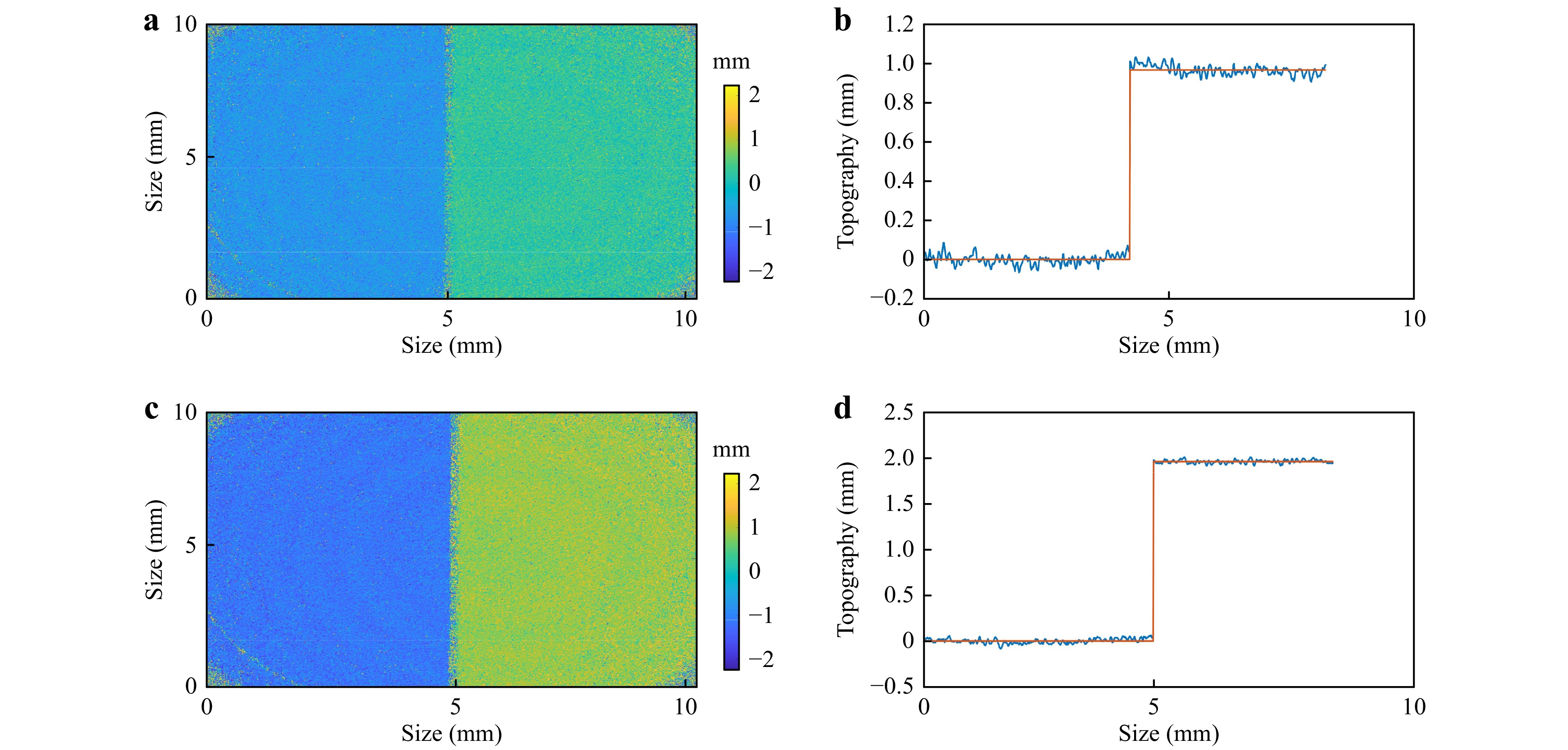
Fig. 7 Measurement results of diffuse reflective sample
a topography map representation with a 1-mm step, b topography cross-section for a 1-mm step, c topography map representation of a 2-mm step, d topography cross-section for a 2-mm step.However, the quality of dual-wavelength digital holography can be increased when employing more than two wavelengths combined with the application of a hierarchical demodulation30. However, this comes at the cost of either an increased complexity of the setup to enable single-shot imaging or an increased acquisition time.
-
To further highlight the advantage of the dual-wavelength method with respect to its independence regarding the color of the object surface, two car body parts, which have the same shape but different colors (red and black), were chosen. These two non-cooperative parts were placed close to each other. The surface of the testing parts consisted of a combination of specular and diffuse reflective surface areas. The upper layer was varnished, whereas the bottom was covered with industrial paint. Because the upper varnished layer is predominantly transparent with a thickness of 30 µm, light passes through it in an almost undisturbed manner. Therefore, a major part of the light interacts only with the paint. In Fig. 8a, non-cooperative surfaces are represented. The yellow rectangle marks the investigated region of 10 × 10 mm2, where the two parts are joined. Fig. 8b, c represents the topography map and its cross-section, respectively, with the red line representing the average height value. The corresponding average profile height between the touched surfaces was 2.98 mm.
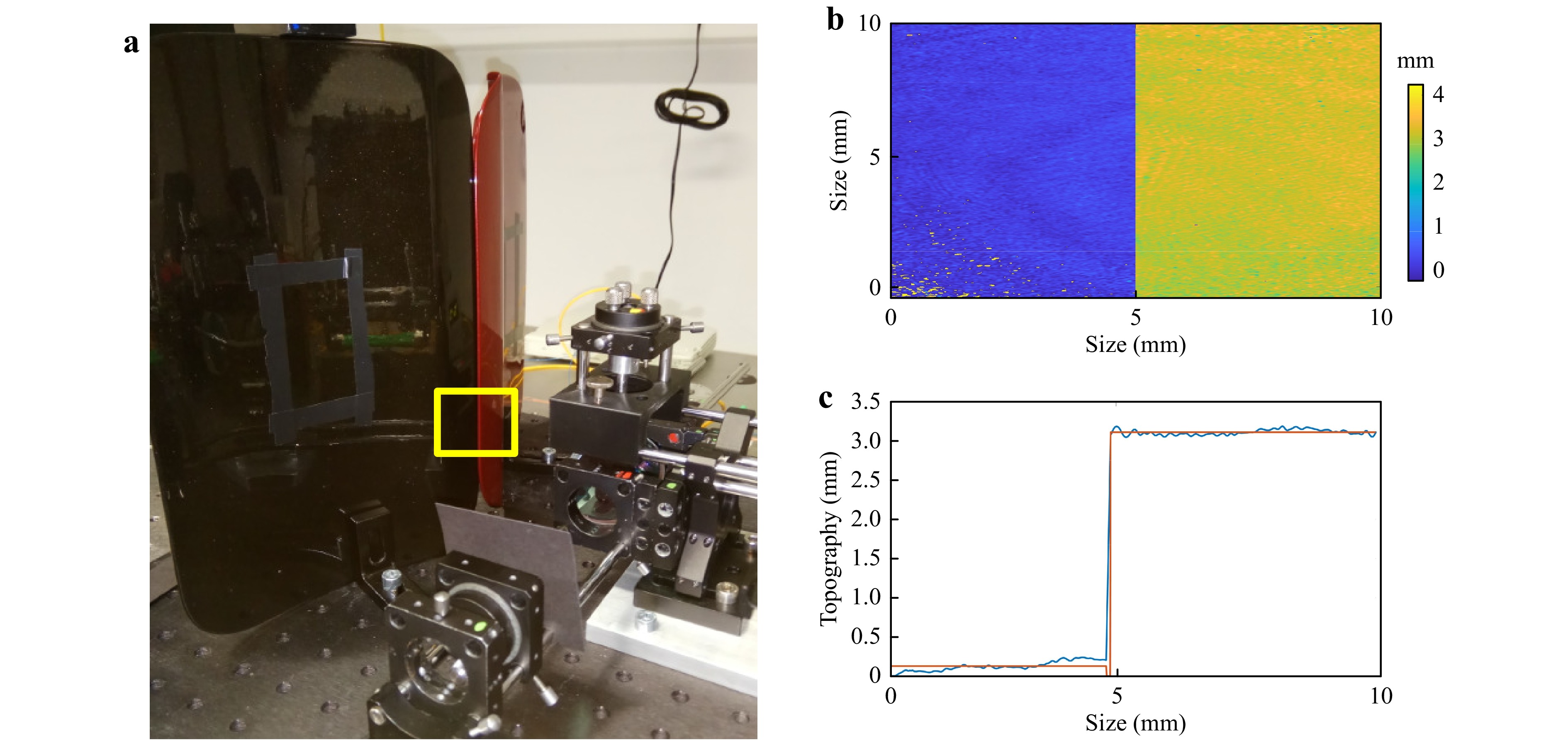
Fig. 8 Non-cooperative-colored surfaces and measurement results
a setup with non-cooperative-colored surfaces, b topography map, c topography cross-section plot. -
A dual-VCSEL-based dual-wavelength digital holographic system was developed. It can deliver a measurement uncertainty of 1/500th of the measurement range for a full-field optical surface topography measurement within a single shot. Hence, it enables the investigation of dynamic events or harsh environmental conditions with more than 100 million recovered topographic data points within 1 s. The challenge of obtaining the required exact knowledge of the two wavelengths during the experiment was addressed via the development of a compact dual-VCSEL light source, which is spectrally highly stabilized using a well-suited precise temperature control (Peltier element) and current control unit. This approach resulted in a wavelength drift of 1 pm over 24 h, and is applicable to the entire tunable wavelength range of approximately 1.5 nm.
In this manner, we could develop a reliable measurement system that delivers a good measurement uncertainty of 0.22% of the measurement range. We demonstrated the versatile applicability of our single-shot VCSEL-based dual-wavelength system using specular reflective, diffuse reflective, and differently colored samples. The dual VCSEL approach that is demonstrated can further be improved, delivering an even better measurement uncertainty. This can be accomplished by either performing multiple recordings while changing the wavelength, resulting in another ideally smaller synthetic wavelengths, or by the application of more than two VCSELs on a common actively temperature-stabilized Peltier element. This element enables the simultaneous recording of information provided by different wavelengths. However, this comes at the cost of increased complexity of the setup and reduced dynamic range for each wavelength in the recording process. The use of additional wavelengths, which are spectrally more distant from each other, may result in speckle decorrelation. In combination with a setup with a high numerical aperture, all micro-topographic parameters (shape, waviness, and roughness profile) can be recovered31. To date, in our case, special emphasis has been placed on the recovery of the shape with reduced speckle noise. Therefore, the two speckle-patterns that are recorded have a high degree of correlation, which hinders the retrieval of roughness information from the dual-wavelength phase-difference map. The speckle from the individual wavelength reconstruction and its corresponding contrast can only be used to derive roughness-related parameters and not the roughness profile itself. Typical roughness-related parameters that can be extracted from the speckle contrast are the arithmetic mean (Ra) roughness value or correlation length32. However, in addition to the recovery of these few mostly integrative roughness parameters, the object under investigation needs to satisfy the weak scattering condition, and pre-calibration becomes necessary. Therefore, there is little industrial benefit when employing speckle-correlated wavelength pairs to recover roughness parameters33.
Finally, the compact and spectrally highly stabilized VCSEL-based dual-wavelength method can be extended to the multi-wavelength method. This step enables a further reduction in measurement uncertainty, and in the case of wavelength pairs causing speckle-decorrelation, the recovery of the roughness profile, from which all relevant roughness parameters can be derived.
-
In this study, we demonstrated dual-wavelength digital holographic interferometry based on a highly spectrally stabilized dual-VCSEL light source, which is tunable up to a 2-nm difference in wavelength. Stability is achieved through accurate thermal and current stabilization. Therefore, without any reference or monitoring system, it can be applied for topography measurements with a synthetic wavelength in the millimeter range, while still maintaining a sufficiently high measurement uncertainty. The setup was realized in a compact, lightweight, and robust manner using optical fibers, which were directly bonded to the active emission area of each VCSEL.
The dual-wavelength measurement system was realized in a single-shot manner with an exposure time of only a few milliseconds. This means that both wavelengths are simultaneously exposed to changes in the environment, such as heat drift, vibrations, or air flow. Moreover, owing to the short integration time and the usual low-frequency nature of these changes, the environmental changes are frozen in time. In the phase subtraction process, the influence of the environment is minimized. Hence, the measurement system is well suited for in-line and online monitoring during the production process. Furthermore, it can be applied to non-cooperative surfaces, which may be scattering, specular reflective, or a combination of both. In addition, it is not restricted to any color on the surface. Therefore, it enables the traceability of parts that are subjected to changing surface properties during the production cycle, such as car bodies.
-
We mounted two VCSELs with an emission wavelength of 850 nm in close proximity to each other, i.e., approximately 1.2 mm, on a common heat sink that was equipped with a thermistor to read the temperature and a thermo-electric cooling element (TEC) to stabilize the temperature, as shown in Fig. 9. To simplify the further handling of the emitted light and to enable separate beam steering for both wavelengths, the active emitter surface of each VCSEL was directly bonded to a single-mode fiber. The fiber bonding was performed using a UV-curing epoxy resin. The final fiber-bonded dual-VCSEL light source is shown in Fig. 10, whereas at each fiber end, light of the corresponding VCSEL with mutually different wavelengths is emitted.
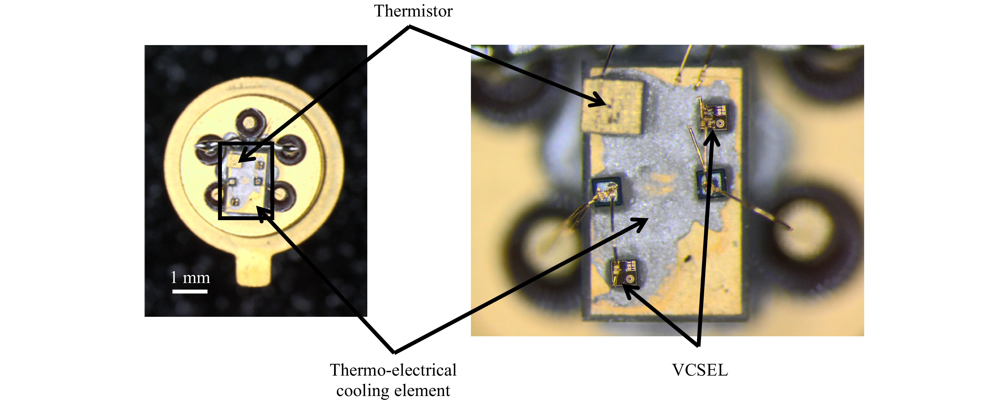
Fig. 9 Two VCSELs mounted on a common TEC.
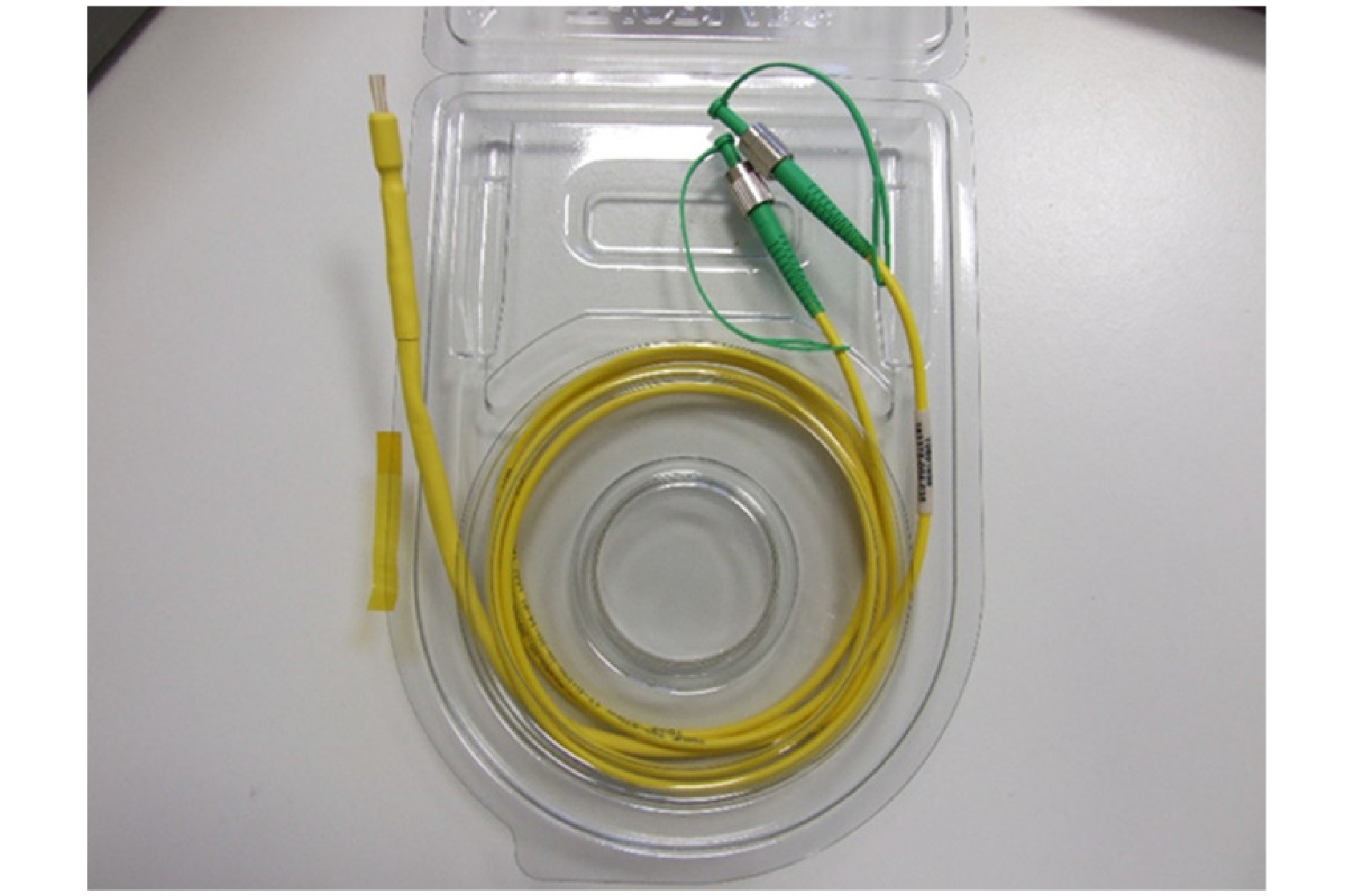
Fig. 10 Dual-VCSEL single-mode fiber light source.
A control circuit based on an Arduino microcontroller and the required electronic components was implemented in the ILM electric engineering stores, by which the temperature was stabilized to 10 mK and the current could be set from 3 mA to 6.2 mA in 20-µA steps with a current stability of 8 µA. Using a USB connection, the current can be set by a computer.
The wavelength current response of both VCSELs was then recorded using a highly precise wavemeter (HighFinesse, Typ:WS7-60) with a measurement uncertainty of 0.13 pm. The wavelength standard deviation for both VCSELS over 12 h over the entire sweep range was less than 1 pm. However, when switching the system again the next day, the starting point of the curves slightly changed, which may be because of a certain amount of mechanical loading as the VCSELs have been touched when connecting them to the control board. Hence, in principle, the system should be very stable once calibrated. However, to account for any change that may occur daily (mechanical load, changes humidity, changed air pressure), a reference object can be used each day before starting the measurement, as proposed in Ref. 25. The aforementioned reflective gauge blocks (see Fig. 5) were also used for the calibration, which were only applied once a day before the measurement to calibrate the synthetic wavelength; this wavelength can be calculated from the known topography of the reference objects by rearranging Eq. 2:
$$ {\lambda }_{syn}=\frac{4\pi T}{{\Delta }\varphi } $$ (5) Therefore, we applied a current setting to VCSELs according to the curves shown in Fig. 11, which delivered a synthetic wavelength of more than 8 mm. Using the gauge blocks, a synthetic wavelength of 8.92 mm was confirmed. However, in contrast to Ref. 25, the reference object only needs to be applied once a day before the measurement starts, and not throughout the entire measurement process. In fact, hermetic sealing of the dual-VCSEL source and remote control of the applied current should ensure long-term stability and reproducibility of the emitted wavelength with a spectral drift of below one pm.
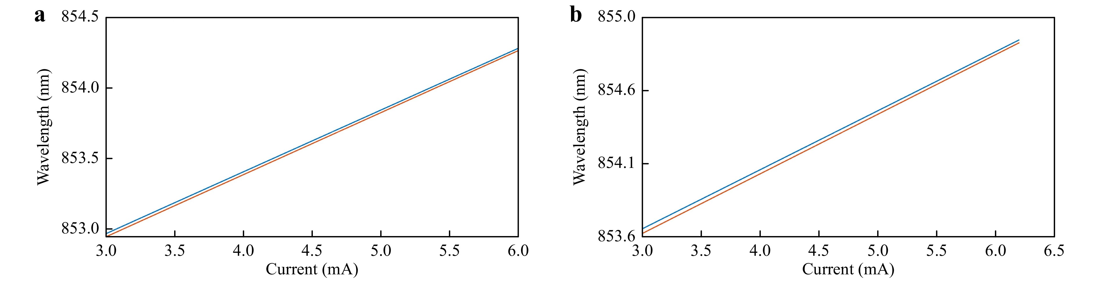
Fig. 11 Current–wavelength diagram over two days, blue first day and orange second day for
a VCSEL 1, b VCSEL2. -
To further improve the compactness of the system and to increase the stability toward environmental changes, the VCSEL-based dual-wavelength setup was implemented using an in-house designed fiber system manufactured by Thorlabs, as shown in Fig. 2a. Through a mating sleeve at the end of the two fiber-bonded VCSELs, the light is launched into a fiber system, which directs 10% of the light into the reference fiber and 90% into the object fiber. Then, the two object fibers are merged again into a common fiber output, by which the intensity at the common fiber tip is reduced by 50%, resulting in 45% of the initial light being launched into the fiber of each VCSEL. Hence, the object fiber emits light that is approximately five times more intense than the reference fiber. Thus, it is ensured that even at steep surface gradients or strongly scattering surfaces, there is sufficient scattered light from the object to produce an interference pattern with high-contrast interference fringes. The best interference contrast is obtained if both the reference and object light have the same intensity. The light emitted from the object fiber was collimated and redirected via a beam splitter plate to hit the object perpendicularly, as shown in Fig. 2b, c. Therefore, the sensitivity vector is the same for all object points, and the opposed-directed illumination and observation vectors standing perpendicular to the object plane result in the highest out-of-plane phase sensitivity. Disturbing reflection effects, which usually occur when employing a cube beam splitter, can be minimized by the application of beam splitter plates. Moreover, because of the thin wall of the beam splitter plate, the occurrence of spherical aberrations is reduced compared to that of a beam splitter cube.
Image plane holograms have been recorded, and offer an advantage in that after applying the separation of the corresponding imaging terms in the Fourier-domain, the reconstructed complex object wave is directly obtained. No further numerical refocusing algorithms have to be applied, which in the case of the direct Fresnel-transform would result in slightly different pixel sizes for both wavelengths that will have to be compensated prior to further processing. Image plane holography is one of the computationally least expensive approaches to recovering the complex object wave. Moreover, the speckle noise is reduced because the corresponding diffraction orders, at least the zeroth and first order according to Abbe’s criterion34, that are transmitted through the aperture are recombined to generate an imaging point and not a speckle. Hence, the speckle noise can be reduced in image-plane holography, as confirmed in Ref. 35, and can further be reduced using a high numerical aperture, which was reported in Ref. 36 for confocal imaging and was confirmed by Ref. 37 in digital holography.
However, more speckles arise in a defocused recording position because of the interference of diffraction orders that correspond to other object points. Speckles were still clearly recorded in the image plane. However, their origin results from the limited aperture, which for high diffraction angles allows only one of the two necessary diffraction orders to be transmitted; this interferes with the other transmitted diffraction orders with an arbitrary phase offset, and hence in an unrelated manner.
This effect is enhanced at scattering surfaces, which can be considered to be composed of various inclined surfaces and structures, and therefore results in diffraction cones that are directed away from the optical axis. At highly scattering surfaces, a fully developed speckle pattern can be obtained, which means that the speckle is the main carrier of information about the object and its surface. In such cases, it becomes a crucial requirement for the successful application of the dual-wavelength method for the recovery of shape at small NA, in which both wavelengths are close to each other, to ensure that both speckle patterns are not decorrelated. When subtracting the phase of such a correlated speckle pattern, which is encoded via interference with the corresponding reference waves, the object shape can be revealed. The previously randomly appearing phase of the individual wavelength reconstruction becomes homogenized after subtracting the phase reconstruction of the second wavelength; thus, the speckle noise is reduced.
According to Ref. 38, if the surface height fluctuations obey Gaussian statistics, the speckle decorrelation caused by the wavelength change can be expressed by the intensity correlation coefficient as follows:
$$ {\left|{\mu }_{T}(\Delta \lambda)\right|}^{2}=\mathrm{exp}\left[-{\left(4\pi \right)}^{2}{\left(\frac{{\sigma }_{T}}{\stackrel-{\lambda }}\right)}^{2}{\left(\frac{\left|{\Delta }\lambda \right|}{\stackrel-{\lambda }}\right)}^{2}\right] $$ (6) The standard deviation of the surface-height fluctuations corresponds to the
$ {R}_{q} $ roughness value. The averaged wavelength and the wavelength difference can both be replaced by the synthetic wavelength, which results in the following simplified expression:$$ {\left|{\mu }_{T}\left(\Delta k\right)\right|}^{2}=\mathrm{e}\mathrm{x}\mathrm{p}\left[-{\left(\frac{4\pi {R}_{q}}{{\lambda }_{syn}}\right)}^{2}\right]=\mathrm{e}\mathrm{x}\mathrm{p}\left[-{\left(4\pi {R}_{q}\Delta k\right)}^{2}\right] $$ (7) where
$ {\Delta }k $ is the difference in wavenumber (k = 1/λ). An intensity correlation value of zero indicates a complete decorrelation, and “one” indicates complete correlation of the intensity speckle pattern. Therefore, the intensity correlation should be larger than 0.95 to ensure that speckle decorrelation can be neglected. By modifying Eq. 7, the maximum difference in the wavenumber$ {\Delta }k $ or its reciprocal parameter,$ {\lambda }_{syn} $ can be calculated to obtain the limit of possible wavelength pairs:$$ {\Delta }k\le \frac{\sqrt[2]{-\mathrm{l}\mathrm{n}\left(0.95\right)}}{4\pi {R}_{q}} $$ (8) The
$ {R}_{q} $ value of our diffusely scattered samples is 1.1 µm, which results in a wavenumber difference of 16.38 mm−1; this corresponds to a synthetic wavelength of 61.03 µm. Our chosen synthetic wavelength is larger than 4 mm, which satisfies the condition set in Eq. 8, resulting in a correlation coefficient of approximately 1.Because the phase information of the two wavelengths is recorded in a single acquisition, speckle decorrelation or instabilities due to environmental conditions can be neglected.
-
The authors would like to acknowledge the support of BMBF under grant “AuMeRo.”
Snap-shot topography measurement via dual-VCSEL and dual wavelength digital holographic interferometry
- Light: Advanced Manufacturing 2, Article number: 29 (2021)
- Received: 28 May 2021
- Revised: 12 November 2021
- Accepted: 18 November 2021 Published online: 29 December 2021
doi: https://doi.org/10.37188/lam.2021.029
Abstract: In this paper, we propose a dual-wavelength digital holographic interferometry method based on a compact dual vertical-cavity surface-emitting laser (VCSEL) source. The source simultaneously emits light from two highly stabilized coherent light sources with slightly different wavelengths. A highly stabilized and adjustable current source enables the application of digital holographic dual-wavelength techniques to measure the shape of an object with height steps of a few millimeters. The wavelength drift over 12 h over the entire measurement range, which was evaluated using a wavemeter, was smaller than 1 pm. In addition to the low measurement uncertainty at large height jumps, the dual-wavelength digital holographic system distinguishes itself by its robustness to environmental disturbances such as air turbulence, heat load, and/or mechanical vibrations. This is enabled via a fiber-based almost common-path single-shot digital holographic acquisition of the information of the two different wavelengths using angular multiplexing. The experimental setup and data evaluation are discussed, and we present measurements of non-cooperative objects with specular reflective and/or diffuse reflective surfaces having different colors.
Research Summary
Compact dual vertical-cavity surface-emitting lasers (VCSEL)delivering unprecedentedly low measurement uncertainty
A spectrally highly stabilized dual VCSEL-source shows great potential for the application in optical metrology. This relates in particular to snap shot recovery of the topography data of an entire area even at non-cooperative surfaces that specular and/or diffuse reflective. State of the art metrology techniques, which can cope with these types of surfaces are white light interference microscopy and confocal microscopy. However, the measurement is very time-consuming ranging from multiple seconds to minutes. Dual wavelength holography can overcome the aforementioned shortcomings. The measurement range and the axial resolution can be adjusted via the choice of the dual wavelength pairs. The measurement uncertainty in dual wavelength holography is strongly linked to a stable wavelength difference between the two wavelengths employed down to a few picometers or even sub-picometers only. VCSELs are particularly well suited for this application since they show a reduced temporal sensitivity compared to edge emitting diodes combined with excellent coherent properties. Therefore, a VCSEL based picometer stabilized dual wavelength source has been configured and has successfully been applied to investigate various objects exhibiting different surface properties.


Rights and permissions
Open Access This article is licensed under a Creative Commons Attribution 4.0 International License, which permits use, sharing, adaptation, distribution and reproduction in any medium or format, as long as you give appropriate credit to the original author(s) and the source, provide a link to the Creative Commons license, and indicate if changes were made. The images or other third party material in this article are included in the article′s Creative Commons license, unless indicated otherwise in a credit line to the material. If material is not included in the article′s Creative Commons license and your intended use is not permitted by statutory regulation or exceeds the permitted use, you will need to obtain permission directly from the copyright holder. To view a copy of this license, visit http://creativecommons.org/licenses/by/4.0/.

 DownLoad: