


-
Color plays an important role as a visual carrier in our daily lives. There are many types of color in nature that are classified according to their production principles1, including bioluminescence, pigmented color, and structural color. Bioluminescence is generated by the energy released from chemical reactions occurring inside bioluminescent organisms. Pigmented or chemical color is typically produced by the selective absorption of incident light. Structural color utilizes micro/nanoscale surface structures to manipulate the reflection/transmission spectrum of visible light through optical interference2. Notably, structural color exhibits some unique characteristics such as iridescence, high resolution, long durability, and a wide color palette. By manipulating the micro/nanostructures, structural coloration has achieved vivid and eye-catching effects3. In nature, structural coloration has been observed in various creatures in the forms of camouflage, communication methods, and sexual selection4−7. For example, under breeding pressure, peacocks have evolved to grow microstructured tail coverts that selectively reflect blue, turquoise, and green light to exhibit iridescent effects8. Inspired by nature, a series of promising applications of artificial structural coloration have been demonstrated, including high-definition displays9, anti-counterfeiting10, refraction index sensing11−13, and photonic gas and vapor sensing14−18.
Nevertheless, the widespread application of artificial structural coloration still suffers from limitations in manufacturing capabilities, in terms of resolution, efficiency, scalability, repeatability, and cost. After decades of development, beam-based methods have emerged as state-of-the-art fabrication techniques for surface texturing, including e-beam lithography19, femtosecond laser structuring20−21, and two-beam laser interference patterning22. E-beam lithography has the unique advantage of high resolution, facilitating the fabrication of optical metasurfaces at a sub-wavelength scale19. However, e-beam lithography has a high manufacturing cost, low material removal rates, and limited processing area. Therefore, it is typically used as a prototyping technique in proof-of-concept studies.
Femtosecond laser patterning with laser-induced periodic surface structures is another popular surface texturing tool23. Through nonlinear laser-matter interactions, periodic microstructures have been manufactured on various metallic and non-metallic surfaces for structural coloration24. However, the grating spacing is subject to the wavelength of the laser source, which limits this technology in terms of producing structural colors with arbitrary resolutions. Two-beam laser interference patterning is another attractive alternative for creating micro/nanoscale surface structures through the local ablation of material surfaces, induced by photo-thermal interactions between lasers and materials. The resolution of the structure spacing can be adjusted by modulating the laser wavelength and included angle between the two interference beams25. However, two-beam laser interference patterns have the shortcoming of poor surface quality owing to disordered material flows.
In addition to beam-based processes, ultraprecision cutting using single-crystal diamond tools has emerged as a novel and cost-effective fabrication method for structural coloration26. Because of extreme tool sharpness (several tens of nanometers in edge radius), diamond cutting can generate micro/nanostructures at the near-wavelength scale with an optically qualified surface finish27−29. Two processes based on diamond cutting have been demonstrated for the scalable and flexible manufacturing of structural colors, namely vibration-assisted texturing30 and fly cutting31−32. Fly cutting generates microstructures by directly replicating the tool geometry. The feed rate can be changed pixel-by-pixel in a controllable manner to program the grating spacing. The generation rate is typically only 50 Hz (corresponding to a spindle speed of 3000 rpm)33, which is the main drawback of fly cutting for structural coloration. In contrast, vibration-assisted texturing utilizes high-frequency and small-amplitude tool modulation to generate grating-type structures down to the submicron scale through periodic overlapping between the tool and material surface. The generation rate can reach ultrasonic frequency (typically from 20 to 40 kHz) when using a resonant-type tool30. By changing the vibration frequency34 or nominal cutting velocity35, the grating spacing can be programmed to render high-resolution images with structural color.
Ultraprecision diamond cutting, particularly the novel processes represented by vibration-assisted texturing and ultraprecision fly cutting, has presented an opportunity for industrial-scale implementation of structural coloration36−37. These techniques have the unique advantages of a high material removal rate and high geometrical accuracy. The cross-sectional profiles of grating-type structures can be accurately controlled to enable the reliable prediction of diffraction light fields. Furthermore, it is possible to achieve surface texturing on a free-formed surface, or even combine surface texturing and generation steps with ultraprecision cutting-based techniques38.
However, thus far, all of the available outcomes of ultraprecision cutting for structural coloration, reported in the literature, have been achieved on metallic (ductile) materials. The diamond surface texturing of non-metallic materials (brittle), down to the wavelength scale (micron level), is still challenging and unproven. This is because the cutting mechanisms of brittle materials, such as silicon and acrylic polymers, differ from those of ductile metals. For example, based on the intrinsic brittleness of silicon, it is extremely difficult to machine silicon in the ductile regime or plastically remove material to create a crack-free surface finish, much less generate a micro/nanostructured surface. Although it seems possible theoretically, successfully demonstrating vibration-assisted texturing of wavelength-scale structures on silicon has not been reported owing to these stringent and complex machining conditions.
In this study, the vibration-assisted ultraprecision texturing of non-metallic and brittle materials in the ductile regime for structural coloration was successfully demonstrated. Two widely used non-metallic engineering materials were considered: silicon (ceramics with high brittleness and broad applications) and acrylics (polymers and transparent materials). Both single-color blocks and color images were rendered on silicon and acrylics to demonstrate the structural color. To achieve this goal, an elliptical vibration tool was used to evaluate the ductile-regime texturing conditions. Owing to the sensitivity of the cutting conditions, the vibration trajectories were carefully optimized for both a crack-free surface finish and attainable surface structure geometries (spacing and depth). We revealed the cutting mechanism of the ductile-regime texturing of brittle materials, and demonstrated the surface texturing of grating-type microstructures in the ductile regime with controllable grating spacings (ranging from 0.75 to 4 μm), where each grating was directly machined in a single vibration cycle.
-
The structural colors produced on silicon and acrylic surfaces by vibration-assisted diamond texturing are presented in Fig. 1 and 2, respectively. Fig. 1a–c present the iridescent effect of a textured silicon block under different illumination angles, which was obtained at a cutting velocity of 2.0 mm/s, vibration frequency of 2000 Hz, and cross feed of 20 μm. The corresponding surface morphology was characterized using an optical microscope, as shown in Fig. 1d; here, the spacing of the periodic grating-type microstructures is approximately 1.0 μm. As shown in Fig. 1a–c, the silicon surface exhibits various vivid colors under different incident light angles in the absence of any pigments.
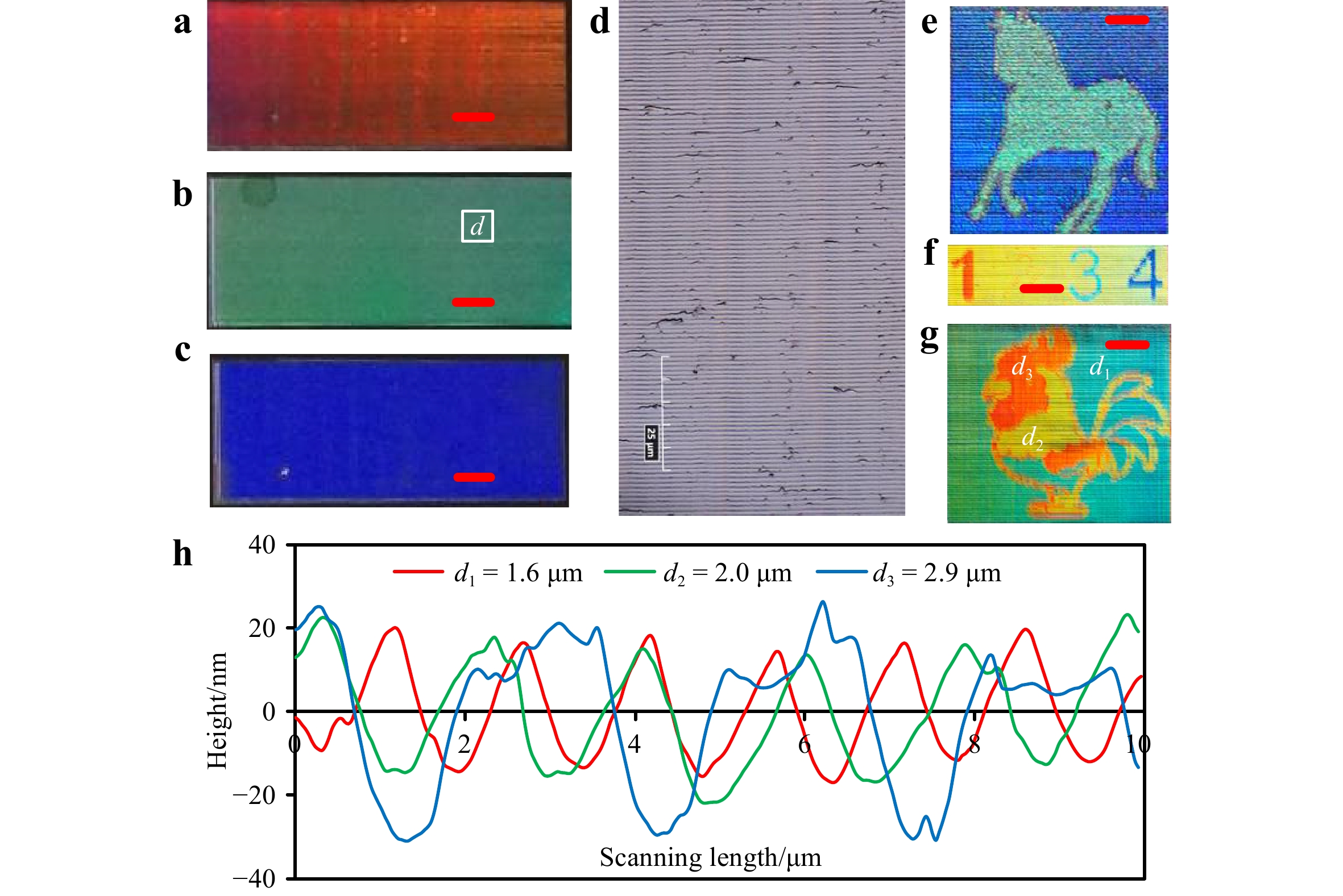
Fig. 1 Results of structural coloration on silicon (red scale bars = 0.5 mm, pixel size = 20 × 20 μm).
a–c Iridescent effects of textured silicon under different illumination angles θi of 75°, 55°, and 40°. d Optical image of machined grating structures on silicon. e–g Image rendering results of a horse, a rooster, and digits with an illumination angle θi of 45°. h Cross-sectional profiles of grating-type structures at selected locations in the rooster image.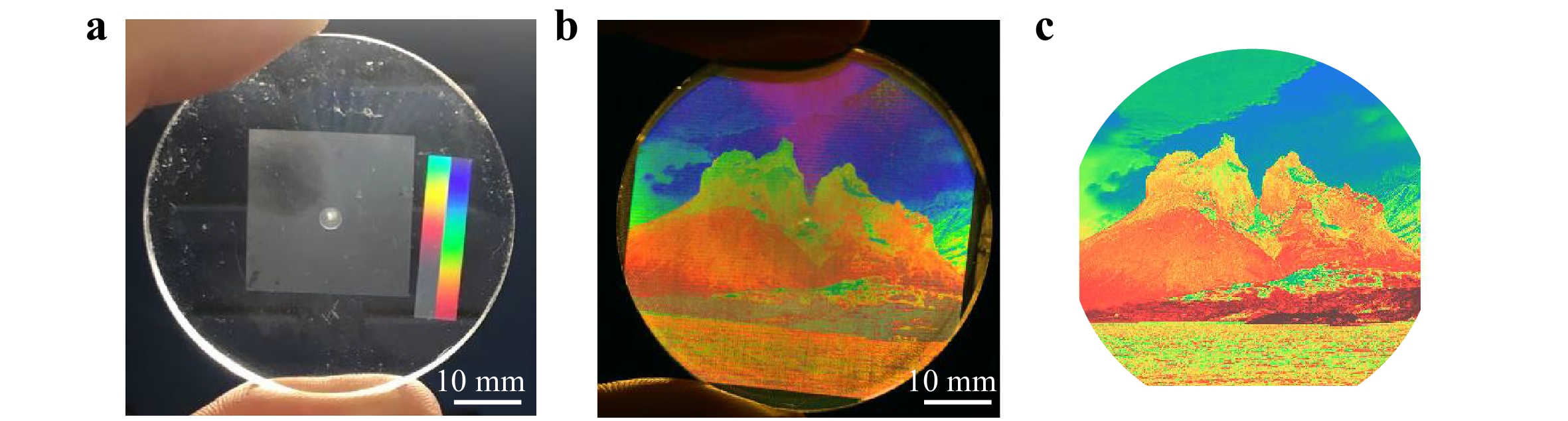
Fig. 2 Structural coloration results on the surface of an acrylic polymer.
a Iridescent visual effects of color blocks. b Rendered landscape painting (pixel size = 20 × 20 μm, illumination angle θi = 45°). c Simulated appearance of the structural coloration.The texturing of tunable grating spacings for color image rendering was demonstrated using silicon samples, as shown in Fig. 1e–g. The pixel size for image rendering was 20 × 20 μm. By regulating the grating spacing and cutting velocity, the pixel-based color images were reproduced on the silicon surface. Fig. 1e presents a horse image with two tones in the foreground and background, where the grating spacings for the foreground and background are 1 and 2 μm, respectively. Fig. 1f presents colored digits, each of which has a different grating spacing. Fig. 1g presents a multicolored rooster image with the selected atomic force microscope (AFM) measurements of the cross-sectional profiles at three different locations. As shown in Fig. 1f, the grating spacings for the different colors are 1.6, 2.0, and 2.9 μm.
Fig. 2 presents color blocks and landscape paintings on acrylic. The grating spacing for the color blocks was maintained at 1.5 μm. The pixel size of the landscape painting was 20 × 20 μm, so the cross feed was maintained at 20 μm. Accordingly, the cutting velocity was adjusted in the range of 2.2–4.2 mm/s at a fixed interval of 20 μm; consequently, the average texturing rate can be calculated as 4.0 mm2/min. The vibration frequency was set to 2000 Hz; hence, the grating spacings for the landscape painting were in the range of 1.1–2.1 μm. Fig. 2c presents the simulation results for structural coloration, according to the modified scalar diffraction theory, as detailed in the Materials and Methods.
-
Grating-type microstructures on monocrystalline silicon surfaces with different spacings were generated using ductile-regime diamond texturing. Optical images of the textured results are presented in Fig. 3a, and the AFM measurement results for the grating cross-sectional profiles are presented in Fig. 3b. As shown in Fig. 3, the gratings with spacings ranging from 0.75 to 4 μm with good surface quality were successfully fabricated, which are sufficient for the full-field production of structural color. The grating depth ranges from 30 nm at a spacing of 0.75 μm to approximately 90 nm at a spacing of 4 μm. However, the gratings with a spacing lower than 0.75 μm were not successfully generated because of the limited sharpness of the cutting edge (the edge radius was approximately 0.2 μm in this study)39. There is no definite upper limit for the achievable grating spacing if the ductile-regime texturing conditions can be satisfied. The conditions for ductile-regime texturing are discussed in detail below.
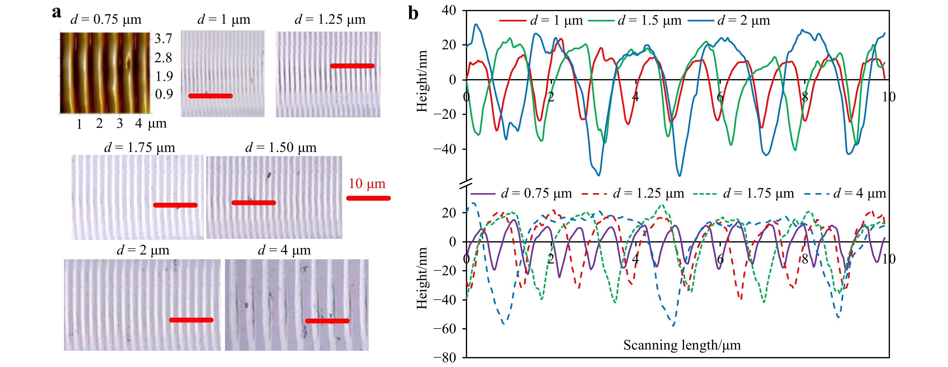
Fig. 3 Textured grating-type results with different spacings.
a Surface topographies of grating-type structures. b Cross-sectional profiles of grating-type structures. (Cutting condition: vibration frequency of 2 kHz, nominal cutting velocity = 2–8 mm/s corresponding to feature spacings of 0.75–4 μm). -
The selected representative non-metallic materials, namely monocrystalline silicon and acrylic polymers, are considered to be brittle materials. It is difficult to generate a crack-free surface on brittle materials using mechanical machining based on their intrinsically low fracture toughness40, which causes the surface to fracture because of crack propagation. Therefore, the most challenging part of vibration texturing for structural coloration on non-metallic materials is to generate a predictable grating geometry with a high aspect ratio (grating depth over spacing), while maintaining suitable cutting conditions for a good surface finish.
Elliptical vibration-assisted texturing typically utilizes a relatively large nominal cutting velocity, as shown in Fig. 4b. The scallops formed by the overlapping tool trajectories create conjunctive microstructures on the material surface30. Each vibration cycle generates a discrete surface feature during texturing. The microstructure generation rate is equal to the vibration frequency. Hence, this texturing process can potentially lead to the high-efficiency texturing of gratings using a high-frequency vibration tool. Because each grating feature is machined in a separate vibration cycle, the trajectory amplitudes must be carefully determined, to ensure that (1) the material is removed without damage to the surface and (2) a high aspect ratio can be achieved with minimal interference between the tool flank and workpiece.
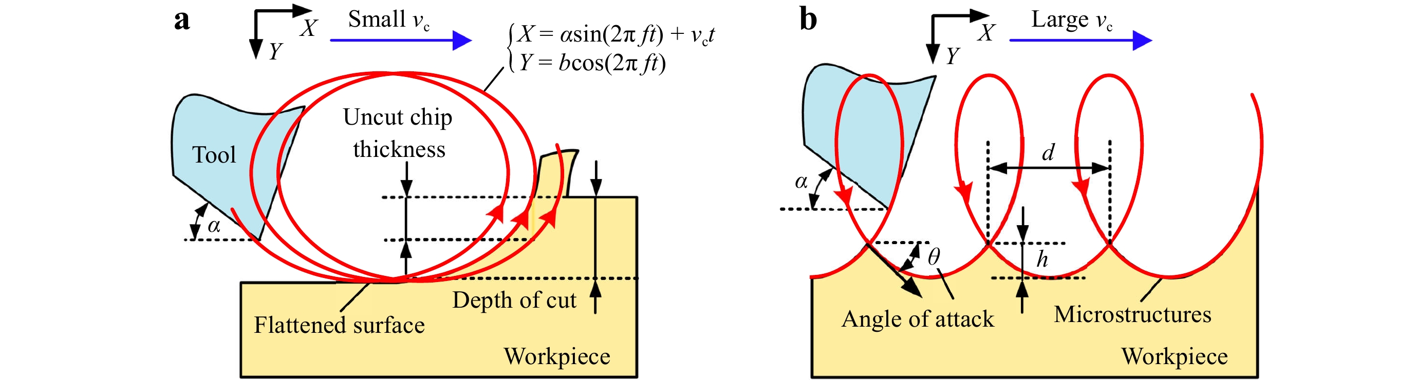
Fig. 4 Illustration of elliptical (2D) vibration cutting with different nominal cutting velocities vc:
a Small vc; b Large vc.As shown in Fig. 4a, with the elliptical vibration of a diamond tool forming an overlapping trajectory, the uncut chip thickness can be significantly reduced, especially under a relatively small nominal cutting velocity41. With a decrease in the undeformed chip thickness, the material removal mechanism of the silicon undergoes a transition from a brittle regime to a ductile regime42, where the material is removed through plastic deformation to create a crack-free surface. Conversely, elliptical vibration texturing utilizes a tool return motion in each vibration cycle to generate high-aspect-ratio features with extremely small spacings, by avoiding interference between the tool flank and workpiece. Based on these assumptions, the tool vibration trajectory can be theoretically and experimentally evaluated to optimize the cutting conditions.
-
The tool vibration trajectory affects the geometry and surface finish of the generated microstructures. The key geometries of the generated grating-type microstructures are depth h and spacing d. Additionally, the angle of attack θ characterizes the instantaneous cutting direction of the tool when it begins to engage the workpiece, as shown in Fig. 4b. This angle affects the tool–workpiece interaction, and should be well controlled to avoid the effects of interference between the tool flank and material surface. The relationship between the process parameters and microstructure geometries, as well as the angle of attack, can be described as
$$ \left\{ {\begin{array}{*{20}{l}} {d = \dfrac{{{v_{\text{c}}}}}{f},h = b - b\cos \left( {2\pi f{t_1}} \right)} \\ {\theta = \arctan \left( {\dfrac{{\sin \left( {2\pi f{t_1}} \right) \cdot b/a}}{{\cos \left( {2\pi f{t_1}} \right) + {\text{HVR}}}}} \right)} \end{array}} \right. $$ (1) where a and b are the elliptical vibration amplitudes in the cutting and depth-of-cut (DOC) directions, respectively; f is the vibration frequency; vc is the nominal cutting velocity; HVR is the horizontal velocity ratio; and t1 is an intermediate time instance. The HVR and t1 can be derived from the following equations:
$$ \left\{ {\begin{array}{*{20}{l}} {{\text{HVR}} = \dfrac{{{v_{\text{c}}}}}{{2\pi fa}}} \\ {\sin \left( {2\pi f{t_1}} \right) + \left( {{\text{HVR}} - 2\pi } \right) \cdot \left( {2\pi f{t_1}} \right) = 0} \end{array}} \right. $$ (2) When a circular diamond tool with a nose radius R is used, the textured gratings are slightly moon-shaped. Because the DOC is much smaller than R, the width w of the grating can be calculated as
$ {{w = 2}}\sqrt {{{2R}} \cdot {\rm{DOC}}} $ . The lateral overlap of neighboring gratings in the cross-feed direction may induce minor defects on the machined surface, as shown in Fig. 1d. The lateral overlap of the neighboring gratings can be avoided by setting the cross feed to be slightly larger than w. However, based on the inevitable irregularity of the workpiece surface, the actual DOC may vary with position, resulting in the lateral overlap of the neighboring gratings. We further analyzed the optical images of the machined surface using a fast Fourier transform, as shown in Fig. 5. In the cutting direction, the major peak represents the grating spacing at 1 μm; meanwhile, the noise in the low-frequency range indicates random defects, which do not exhibit a particular periodic distribution. In the cross-feed direction, no significant peak values can be identified, indicating that the cross-feed marks are not apparent.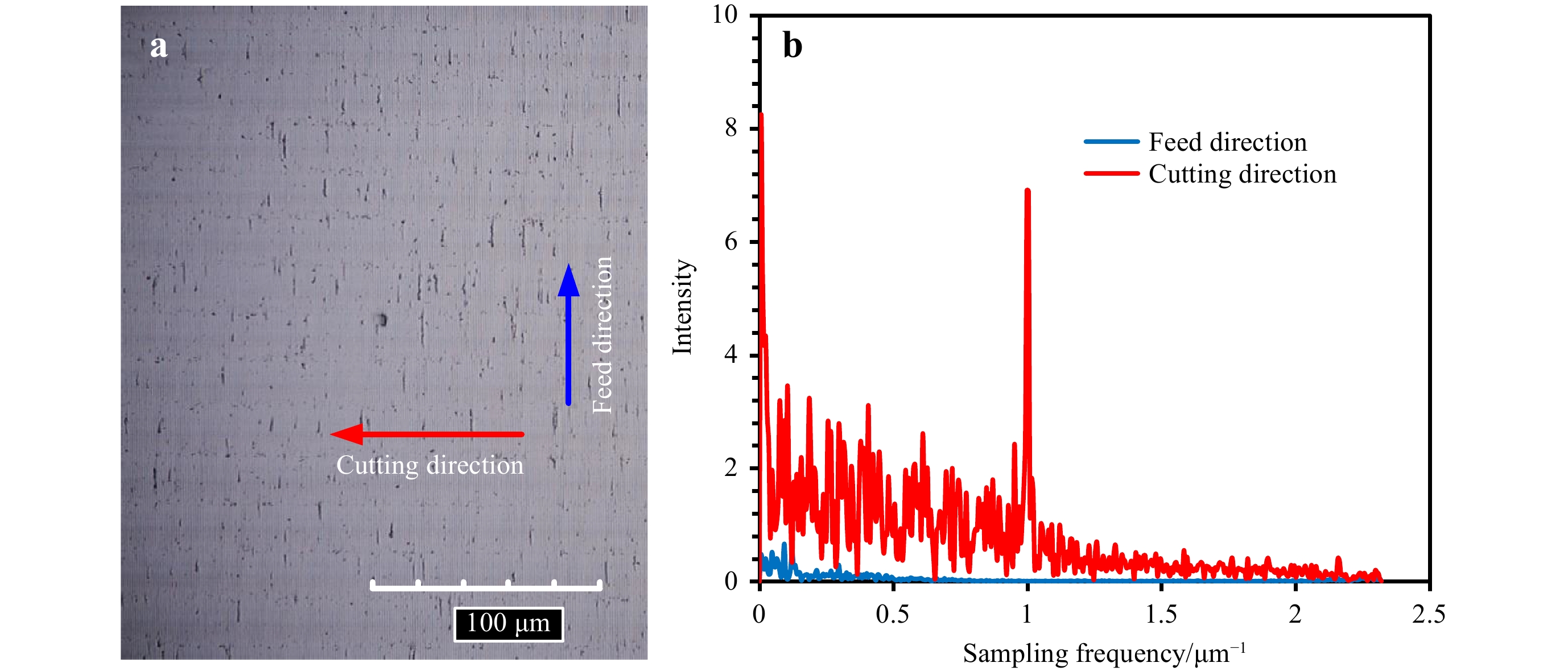
Fig. 5
a Textured silicon surface for image analysis. b Results of fast Fourier transform. -
Examples of typical textured results in the ductile and brittle regimes are compared in Fig. 6a, b, which reveal a drastic difference in the surface quality. The cutting chips obtained during ductile- and brittle-regime texturing are also presented in Fig. 6c, d, respectively, which represent distinct material removal modes. In the ductile regime, the cutting chips are strip-shaped, verifying that each feature is machined in a separate vibration cycle. In the brittle regime, the cutting chips are block-shaped. This indicates that the material is removed via uncontrollable crack generation and propagation, resulting in unacceptable surface quality. In addition to the surface quality and cutting chips, the material removal modes affect the tool life. Tool wear in brittle-regime texturing was much more rapid than that in the ductile regime. Moreover, tool edge chipping can be observed in brittle-regime texturing. In ductile-regime texturing, the tool gradually becomes blunt owing to abrasion.
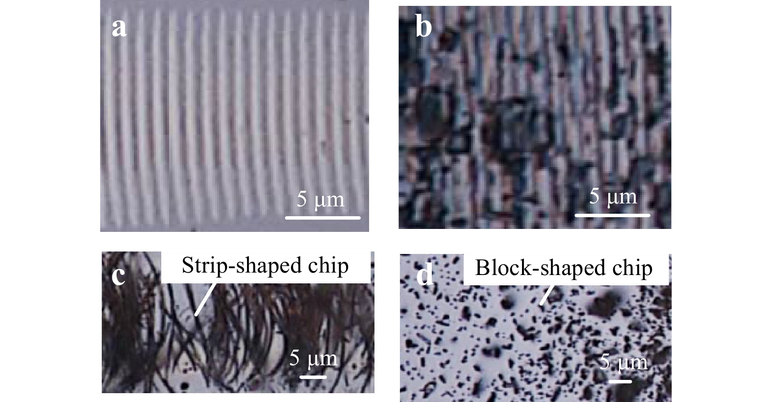
Fig. 6 Comparison of ductile- and brittle-regime machining.
a Ductile- and b brittle-regime textured microstructures on silicon. Chips obtained in the c ductile- and d brittle-regime texturing of silicon.The identified critical depth that separates the ductile regime from the brittle regime is plotted against the vibration amplitude a, grating spacing d, and HVR in Fig. 7a, b. A larger vibration amplitude a in the cutting direction is beneficial for an increase in the critical depth or ductile cutting range. For a fixed vibration frequency, the critical DOC sharply decreases with an increase in the nominal cutting velocity, but does not exhibit apparent dependence in conventional diamond machining. Additionally, for a fixed vibration frequency, when the nominal velocity is small, the critical DOC is significantly enhanced, similar to the case of conventional elliptical vibration cutting. The critical DOC converges to the case without vibrations with a larger velocity.
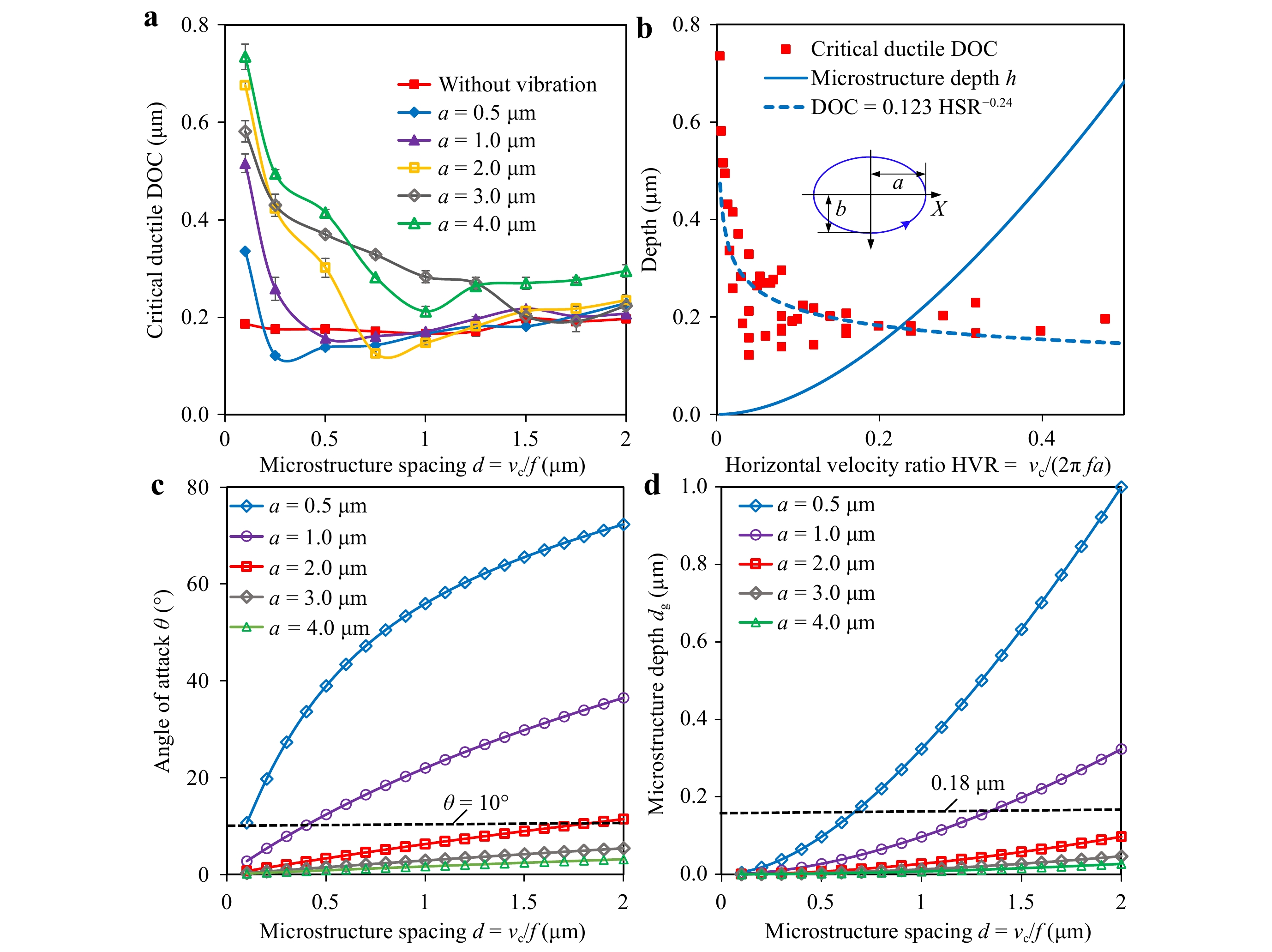
Fig. 7 Evaluation of process parameters.
a Identification of the critical ductile DOC. b Effects of the HVR on the critical ductile DOC. c Effects of the vibration amplitude in the cutting direction on the angle of attack. d Effects of the vibration amplitude in the cutting direction on the grating depth.The interactive effects of the vibration amplitude and nominal cutting velocity on the critical ductile DOC are presented in Fig. 7b. The experimental data for the critical ductile DOC were fitted using a power function of
$ \text{DOC}\text{}\;{=}\;\text{}\text{0.123}\text{}\; \times\; \text{}{\text{HVR}}^{{-}\text{0.24}} $ with an R-squared value of 0.6. The critical ductile DOC is inversely proportional to the HVR, whereas the grating depth is positively related to the HVR. Therefore, a set of contradictory conditions exists for balancing the enhanced critical depth and high aspect ratio of the gratings. The nominal cutting velocity is typically determined by the functional requirement (grating spacing), which cannot be set arbitrarily. Therefore, given a fixed structure spacing, an increase in the vibration amplitude a will enhance the ductile cutting range, but decrease the grating depth or its aspect ratio. Notably, when fabricating grating structures via elliptical vibration texturing, the critical DOC is not significantly improved compared to cutting without vibration, unlike conventional elliptical vibration cutting.To maintain the ductile-regime texturing of silicon during the entire cutting cycle, two conditions must be satisfied. First, interference between the tool flank and workpiece must be avoided to prevent impact-induced crack generation. Second, the generated structure depth must be maintained within the critical ductile DOC. These two conditions are further analyzed in Fig. 7c, d, based on Eq. 1. Fig. 7c presents the dependence of the angle of attack on the microstructure spacing and vibration amplitudes. The angle of attack θ increases with an increase in the microstructure spacing or a decrease in the vibration amplitude a. It should be kept smaller than the clearance angle α to avoid impact. For a clearance angle α = 10°, the vibration amplitude in the cutting direction should be greater than or equal to 2 μm, to ensure an angle of attack θ < 10°.
The elliptical trajectory also significantly affects the microstructure depth. As shown in Fig. 7d, the grating depth h increases with an increase in the grating spacing d and a decrease in the vibration amplitude a. From this perspective, a smaller vibration amplitude is preferred for a higher aspect ratio. However, the criteria for ductile-regime cutting must also be satisfied. In the lower-bound case, the grating depth should be kept smaller than the critical DOC (approximately 180 nm), as indicated by the dashed line in Fig. 7d.
The elliptical vibration trajectory should be optimized by considering both the angle of attack (to avoid interference) and critical DOC (to maintain ductile-regime cutting), to achieve the largest possible aspect ratio. According to this analysis, the elliptical vibration trajectory for the ductile-regime texturing of silicon was optimized as a = 2 μm and b = 1 μm.
-
Intuitively, grating-type microstructures can also be generated using simple 1D cutting depth modulation. As shown in Fig. 8, 1D vibration texturing modulates the tool only in the DOC direction; however, in 2D vibration texturing, additional reciprocal motion is added in the cutting direction. In this study, we found that elliptical vibration-assisted texturing exhibited unique advantages in terms of enhanced control of microstructure geometries and surface finish compared to conventional 1D vibration-assisted texturing.
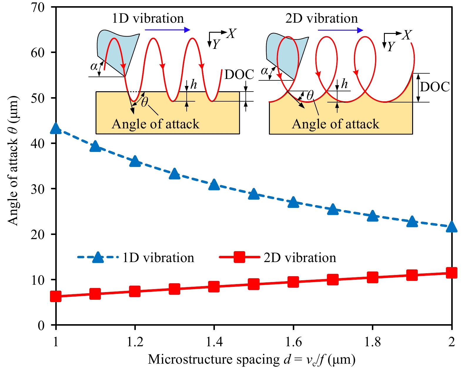
Fig. 8 Comparison of 1D and 2D vibration-assisted texturing.
Simple cutting depth modulation in 1D vibration-assisted texturing will typically result in severely cracked surfaces, owing to the dependence of the grating depth on the nominal cutting DOC, as well as the high angle of attack, thus resulting in flank impact in each cycle. As shown in Fig. 8, the depth h of 1D vibration-textured gratings is sensitive to the changes in the DOC; hence, it is difficult to remain within the critical ductile-regime DOC and obtain repeatable results, considering the inevitable misalignment of the workpiece. Additionally, the angle of attack is significantly larger than that in the 2D case, leading to large tool–workpiece interference that may create a poor surface finish. Overall, the tool is excessively large to scrape into the intended pits in 1D vibration-assisted texturing.
However, in elliptical (2D) vibration-assisted texturing, additional vibration in the cutting direction enables the return motion of the tool, which significantly reduces the angle of attack. Additionally, the generated grating depth h is independent of the nominal DOC. Therefore, the process conditions are consistent, provided the grating spacing is fixed. As shown in Fig. 8, in 2D vibration texturing, the angle of attack is significantly reduced compared to that in the 1D case. It also decreases with a decrease in the grating spacing, which is beneficial for generating microstructures with extremely small spacing.
-
Vibration-assisted diamond texturing has attracted significant attention in the field of structural coloration, owing to its unique capabilities for the accurate control of structure geometry and freeform surface texturing. Currently, the material adaptability of vibration texturing that enables structural coloration is restricted to metallic or ductile materials. In this study, we explored the feasibility and addressed the challenges of vibration-assisted texturing of non-metallic and brittle materials. We found that, unlike general 1D vibration-assisted texturing, the elliptical (2D) vibration cutting process can provide a return motion in the cutting direction, to generate high-aspect-ratio features with extremely small spacings on silicon surfaces. To achieve the maximum feature aspect ratio, the vibration trajectories were optimized to minimize tool–workpiece impact and interference and maintain high-quality cutting conditions. High-spatial-frequency grating-type microstructures with spacings ranging from 0.75 to 4 μm were successfully fabricated on a silicon surface in the ductile regime with optimized elliptical trajectories. The successful structural coloration of silicon and acrylic polymers was demonstrated. Polychromatic images were rendered with controllable grating spacings at each pixel location. In summary, we verified the hypothesis that elliptical vibration cutting can be utilized to generate grating-type microstructures directly on brittle materials, where each grating is created in one vibration cycle.
-
The vibration-assisted texturing process can produce structurally colorized polychromatic images with a high resolution. The fabricated periodic grating-type microstructures can be used to disperse incident white light to provide structural coloration. As shown in Fig. 9a, the perceived color depends on the incident and observing angles. This relationship is governed by the following diffraction equation.
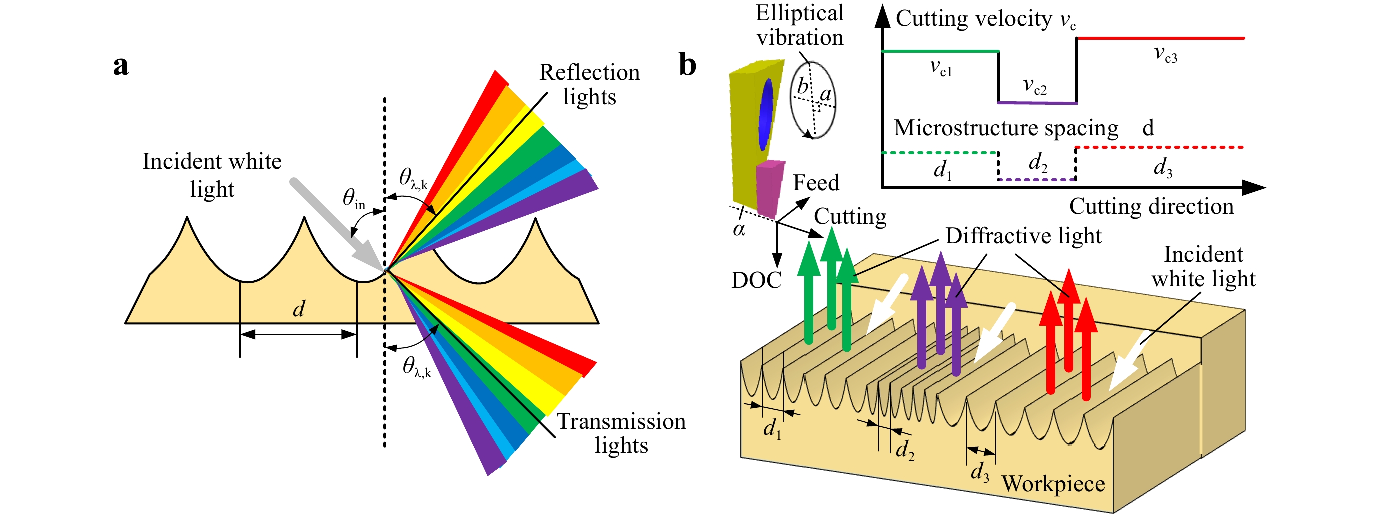
Fig. 9 Principle of structural coloration using vibration-assisted texturing.
a Principle of white-light dispersion. b Grating spacing modulation in elliptical vibration texturing.$$ d = \frac{{k \cdot \lambda }}{{\sin {\theta _{\lambda ,k}} + \sin {\theta _{in}}}} $$ (3) where λ is the light wavelength; θi and θλ,k are the incident and diffraction angles, respectively; and k is the diffraction order. According to Eq. 3, different light wavelengths have different diffraction angles for a given grating spacing. Therefore, the reflected or transmitted spectrum of incident white light can be dispersed to produce colorful visual effects. As indicated by Eq. 3, different light colors can have identical diffraction angles, by accurately controlling the grating spacing. To render a polychromatic image, the grating spacing can be determined at each position according to the desired image pattern under a given observation direction (fixed θλ,k). During vibration texturing, according to Eq. 1, pixelated patches of the gratings with various spacings can be created by dynamically modulating the nominal cutting velocity at each interval, as shown in Fig. 9b.
To determine the color appearance of a textured surface, we modified the scalar diffraction theory to calculate the spatial distribution of the light intensity first43−44. According to the scalar diffraction theory45, for one pixel in the diffraction element with n gratings, as shown in Fig. 10, the distribution of irradiance intensity on a far-field plane from the diffracting aperture can be expressed as
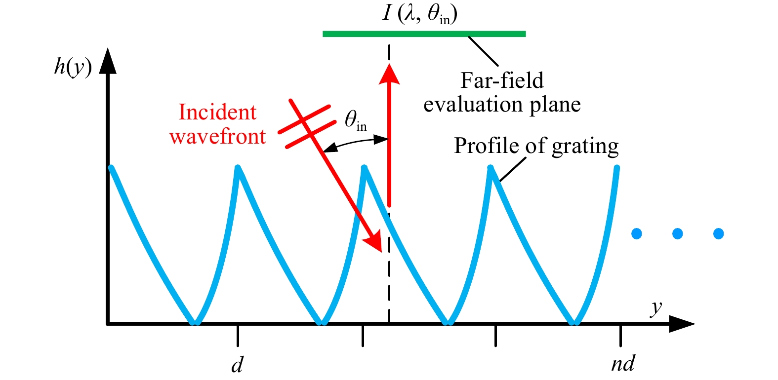
Fig. 10 Scalar diffraction theory for gratings fabricated through vibration texturing cutting.
$$ I(\lambda ,\psi ) = \cos {\theta _{in}}{\left| {{\cal{F}}\{ U(y)\} } \right|^2} $$ (4) where I is the diffracted light intensity, ψ is the observation angle relative to the normal direction of the substrate plane, λ is the wavelength of light, and y is the lateral coordinate along the substrate surface, the direction of which is aligned with the nominal cutting direction. U(y) is the distribution of the complex amplitude of the light field that emerges from the diffractive aperture, which is described as
$$U(y)={{e}^{{}^{-4\pi ih(y)\sin {{\theta }_{in}}}\diagup{}_{{{\lambda }^{2}}}\;}}\left( 0\le y\le nd \right)$$ (5) where h(y) describes the surface profile of a one-pixel diffraction element with n gratings.
$ {\cal{F}} $ denotes the Fourier transform operator, and is defined as$$ {\cal{F}}\{ U(y)\} = \Delta x \cdot \int_{ - \infty }^\infty {U(y){e^{ - 2\pi iy}}{\text{d}}y} $$ (6) where Δx is the width of gratings in the cross-feed direction.
The diffracted light intensities I (λ) for different observation angles ψ can be derived from Eqs. 4–6. Further, the apparent color can be obtained through RGB color conversion, as46
$$ \left\{\begin{array}{c}X={\int }_{\lambda }^{}I\left(\lambda \right)\overline {x}\left(\lambda \right)d\lambda \\ Y={\int }_{\lambda }^{}I\left(\lambda \right)\overline {y}\left(\lambda \right)d\lambda \\ Z={\int }_{\lambda }^{}I\left(\lambda \right)\overline {z}\left(\lambda \right)d\lambda \end{array}\right., \;\;\lambda \in \left[\mathrm{380,780}\right] $$ (7) where
$ \overline {\text{x}} $ ,$ \overline {y} $ , and$ \overline {\text{z}} $ are the CIE 1931 2° standard color-matching functions with a Gaussian approximation47, 48. The obtained XYZ of each corresponding pixel is converted into the sRGB space using the MATLAB function xyz2rgb. Then, the sRGB values are scaled to a range of 0–255 for screen display. In our simulations, the light source was considered to be a daylight source, where the intensity distributions for different wavelengths were approximately uniform. A comparison of the experimental and simulated appearances of the structural coloration results is presented in Fig. 2, which validates the proposed simulation model. -
The experimental setup is presented in Fig. 11. An ultrafast 2D non-resonant vibration cutting tool, with a frequency bandwidth of up to 6 kHz and full stroke of up to 10 × 10 μm, was used to generate the controllable elliptical vibration trajectories49. A direct-drive linear stage and three-axis stage (Aerotech, USA) were used to perform the cutting and cross-feed motions, respectively. A level adjustment stage was used to control the inclination angle of the workpiece. Two types of workpieces were utilized: monocrystalline silicon (crystal plane of (100)) and acrylic polymer. A single-crystal diamond insert (Contour Fine Tooling, UK) was attached to the vibration tool with a nominal rake angle γ0 of −20°, clearance angle α of 10°, and nose radius R of 470 μm.
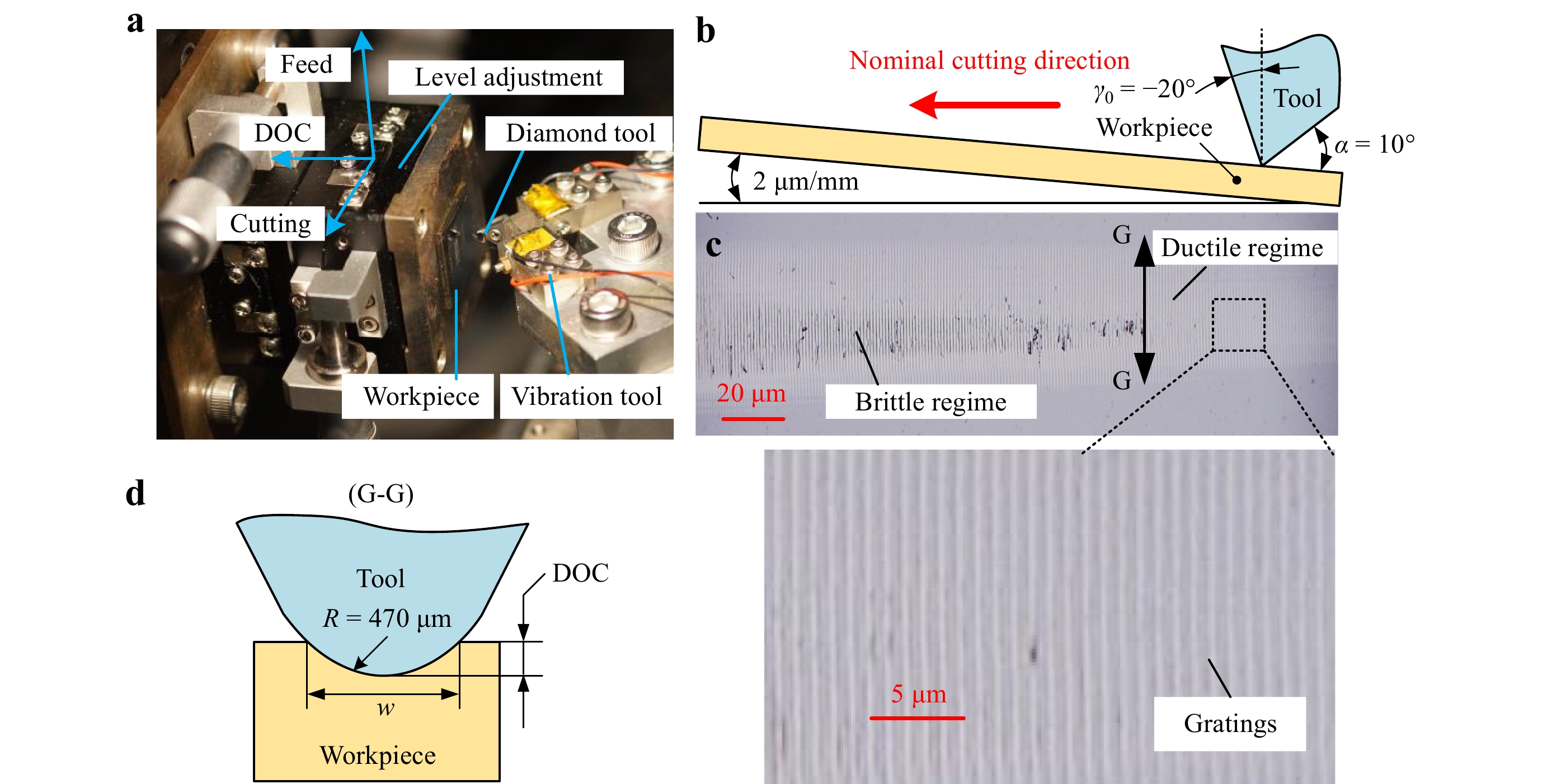
Fig. 11 Experimental setup.
a Experimental device. b Grooving schematic. c Optical image of grooving result. d Relationship between the cutting depth and groove width.Grooving experiments were performed to identify the characteristic critical cutting depth or ductile-to-brittle transition distance of silicon for the conventional and vibration-assisted diamond texturing methods. The detailed experimental parameters are listed in Table 1. The silicon workpiece was inclined at an angle of 2 μm/mm in the crystal direction of <110>. Different cutting velocities ranging from 0.2 to 4 mm/s were used to scratch the workpiece with a gradual increase in the DOC, because of the inclination angle, as shown in Fig. 11b. The machined grooves were observed using a digital microscope (RH-2000, Hirox, Japan). The captured surface morphology is presented in Fig. 11c, from which the distinct transition of the material removal states can be identified. According to the relationship between the cutting width w and DOC, as shown in Fig. 11d, the critical cutting depth in the ductile regime can be obtained to optimize the vibration trajectory. Finally, polychromatic image rendering on both the silicon and acrylic was performed using the optimized vibration trajectory.
No. a (μm) b (μm) vc (mm/s) 1 Without vibration 0.2, 0.5, 1, 1.5, 2, 2.5, 3, 3.5, 4 2 0.5, 1, 2, 3, 4 1 0.2, 0.5, 1, 1.5, 2, 2.5, 3, 3.5, 4 3 2 1 1.5, 2, 2.5, 3, 3.5, 4, 8 Tool vibration frequency f = 2000 Hz Table 1. Process parameters used in the experimental design for vibration trajectory optimization.
-
Two types of optical systems were used to observe and record the structurally colored workpiece surfaces, after machining based on the different transparencies of silicon and acrylic. The silicon was measured in a reflection configuration, whereas the acrylic sample was characterized using a transmission setup. As shown in Fig. 12a, for the silicon surface textured with reflection gratings, the incident white light is on the same side as the digital camera. However, for the acrylic surface textured with transmission gratings, as shown in Fig. 12b, the incident white light is on the opposite side of the digital camera. However, for both optical systems, the optical axis of the digital camera was set to be perpendicular to the workpiece surface.
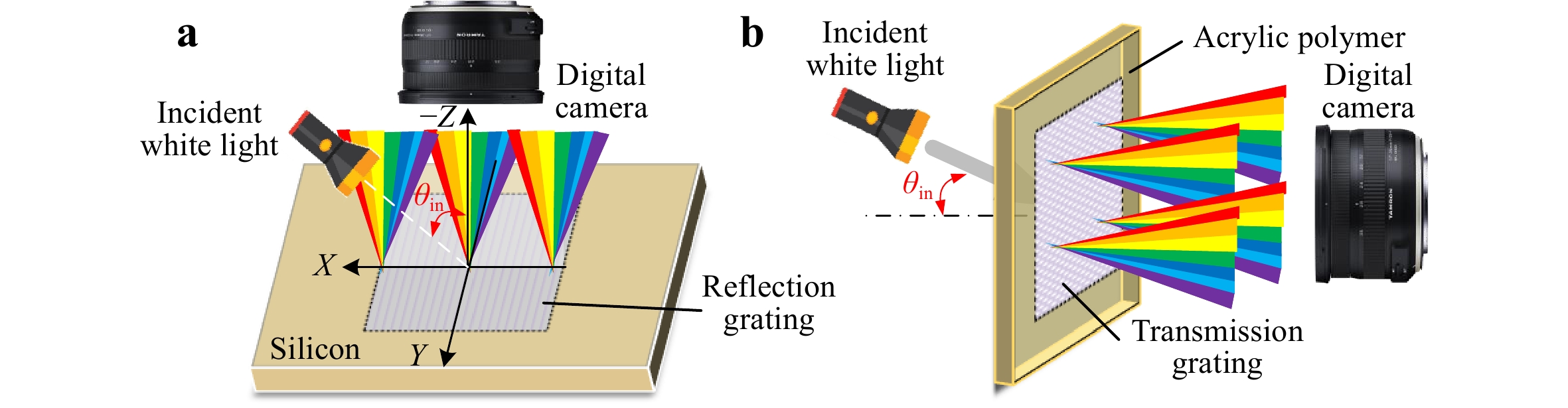
Fig. 12 Optical systems with a collimated light source to observe the structured surfaces.
a System to observe the silicon surface. b System to observe the acrylic surface. -
This research was supported by a start-up fund from the McCormick School of Engineering, Northwestern University, Evanston, IL, USA. This work utilized the Northwestern University Micro/Nano Fabrication Facility (NUFAB), which is supported by the State of Illinois and Northwestern University. Jianjian Wang would like to acknowledge the fellowship support received from the Alexander von Humboldt Foundation. Jianfu Zhang gratefully acknowledges the financial support for this research received from the National Natural Science Foundation of China (Grant No. 51761145103). Yang Yang would like to acknowledge the financial support received from the Open Research Foundation of the State Key Laboratory of Digital Manufacturing Equipment and Technology, China (Grant No. DMETKF2020011).
Structural coloration of non-metallic surfaces using ductile-regime vibration-assisted ultraprecision texturing
-
Jianjian Wang1, 2, ,
 ,
, - Yaoke Wang2, ,
- Jianfu Zhang1, ,
- Yang Yang3, 4, ,
-
Ping Guo2, *, ,
- Light: Advanced Manufacturing 2, Article number: (2021)
- Received: 14 May 2021
- Revised: 24 November 2021
- Accepted: 29 November 2021 Published online: 24 December 2021
doi: https://doi.org/10.37188/lam.2021.033
Abstract: Structural coloration stemming from microstructure-induced light interference has been recognized as a promising surface colorizing technology, based on its potential in a wide array of applications, including high-definition displays, anti-counterfeiting, refractive index sensing, and photonic gas and vapor sensing. Vibration-assisted ultraprecision texturing using diamond tools has emerged as a high-efficiency and cost-effective machining method for colorizing metallic and ductile surfaces by creating near-wavelength microstructures. Although theoretically possible, it is extremely challenging to apply the vibration-assisted texturing technique directly to colorize non-metallic and brittle materials (e.g., silicon and acrylic polymers) with high-quality, crack-free microstructures owing to the intrinsic brittleness of these materials. This study demonstrates the feasibility of direct texturing near-wavelength-scale gratings on brittle surfaces in the ductile regime to fabricate crack-free micro/nanostructures. The effects of tool vibration trajectories on the ductile-to-brittle transition phenomena were investigated to reveal the cutting mechanism of ductile-regime texturing and optimize the processing windows. Structural coloration on silicon and acrylic surfaces was successfully demonstrated by creating programmable and pixelated diffraction gratings with spacing values ranging from 0.75 to 4 μm.


Rights and permissions
Open Access This article is licensed under a Creative Commons Attribution 4.0 International License, which permits use, sharing, adaptation, distribution and reproduction in any medium or format, as long as you give appropriate credit to the original author(s) and the source, provide a link to the Creative Commons license, and indicate if changes were made. The images or other third party material in this article are included in the article′s Creative Commons license, unless indicated otherwise in a credit line to the material. If material is not included in the article′s Creative Commons license and your intended use is not permitted by statutory regulation or exceeds the permitted use, you will need to obtain permission directly from the copyright holder. To view a copy of this license, visit http://creativecommons.org/licenses/by/4.0/.

 DownLoad: