


HTML
-
Holography per se is a way to record both the intensity and phase of a light wave. Unlike traditional photography, which maps 3D wave-front onto the 2D plane through intensity-only recording, holographic image capturing allows for depth-perception and different viewing angels1, 2. more importantly, a mathematical framework which was derived to describe the physical principle of the hologram3−5 could be used to simulate light wave propagation and diffraction pattern from specific diffractive optics elements (DOEs). Given desired diffraction pattern, corresponding DOE could be computed and processed for manufacturing. The rapid growth in computing power of modern personal computers allows computer-generated holograms (CGH) to be digitally produced in a fraction of a second6, 7.
The Iterative Fast Fourier Transform Algorithm (IFFTA) is one of the best known mathematical platforms for evaluating the DOE configuration to obtain the desired far-field diffraction pattern. IFFTA is suitable for getting binary amplitude-only or phase-only CGHs as well as for multi-level phase-only holograms8, 9. The algorithm's core is repeatedly altering between spatial and frequency domains, substituting the phase factor from the previous iteration to the next one. Usually, a root mean squared error (RMSE) is used to compare the calculated far-filed diffraction pattern to the desired image and stop the iteration process. The crucial step of the IFFTA is the phase quantization process. All numerical calculations are usually performed using 32 or 64-bits float numbers, but manufacturing and displaying technologies operate with a much lower bit number (1-8 bits). The quantization step is required to reduce the number of bits. In this work, we will consider and produce a binary hologram (1 bit). In this case, the phase and amplitude holograms are mathematically equivalent. The straightforward approach is to divide phase interval from 0 to 2
$ \pi $ into two equal segments and use$ \pi $ value as a threshold for phase quantization. However, more complicated algorithms were proposed10−12 to find the optimal threshold value and obtain the best possible far-field diffraction outcome. After the quantization step, the resulted hologram is ready to be manufactured.Polymers are promising materials for the production of DOEs13−15. Their optical properties are well known and could be tuned to match optical needs16−18. Some polymers are bio-compatible/bio-degradable such as polylactic-co-glycolic acid (PLGA), poly(ε-caprolactone) (PCL), etc.19 or even has an Food and Drug Administration (FDA) approval for in vivo usage like polylactic acid (PLA)20. PLA is transparent within the visible spectral range, and the performance of the amplitude holograms is mostly independent of the illumination wavelength (only image scale is affected). These properties make it possible to use a large variety of laser sources to reconstruct diffraction patterns. Such attributes makes PLA one of the best materials for manufacturing DOEs, specifically for biomedical applications19.
There are three leading technologies for polymer-based DOEs production:
1. Micro-hot embossing. In this approach, a master mold usually made of nickel or rigid thermo-resistive polymer is pressed into the polymer film. Processed film is heated up to its glass transition temperature21−23. Under pressure and heat, the master mold pattern is transferred onto the surface of the processed polymer.
2. Laser ablation and engraving. The ultra-short laser pulses (nanoseconds and less) perform local polymer removing to form the desired surface pattern of DOEs24−26. Typically, UV lasers were used as most polymers have moderate to significant absorption coefficient in this spectral range.
3. Casting. This method implies using solvents. At first, the polymer is dissolved in the suitable solvent. Then it is casted into a special mold, or the mold itself is dip-coated into the dissolved polymer27, 28. Usually, molds are made out of inert silicone-based polymers like polydimethylsiloxane (PDMS). Master molds should be wettable by the solvent; otherwise, fine surface patterns will not be replicated.
All of the above-mentioned manufacturing methods produce phase-only DOEs patterns either by redistribution polymer volume (micro-hot embossing and casting) or permanently removing local parts of the polymer film (laser ablation or engraving). In order to produce amplitude-only hologram, usually a spot of opaque ink is deposited onto the substrate’s surface. In all of the described methods, the produced DOE only carries information in terms of their diffraction pattern and not physically. In principle, useful bioactive substances could be doped into the ink, but in this case, the cargo mass will be much smaller compared to the proposed approach, and compatibility between light-blocking ink and the drug should be addressed.
We introduce an additive approach of producing biocompatible DOEs using direct drug printing (DDP). Bio -active substances are hot-printed onto the surface of flat polymer film as cargo bits. Spatial distribution of cargo bits forms the precomputed DOE. In our approach, the bioactive substance does not interact with any organic solvents and is placed “as is” onto the inert biopolymer, ensuring no changes in the pharmacological effect of the drug. The resulted film acts as a transmissive amplitude-only hologram. This cargo packaging system, that creates a clear far-field diffraction pattern when illuminated by a coherent light source, can find its place in various biomedical problems. One direct applications of payload holograms is tracking the lifespan of colorless content and measurement of the characteristic release time of active substances under various environmental conditions. The most likely application of our technology is to complement the standard antibiotic testing procedure. Adding a visual channel for tracking the drug release, which requires only the presence of a coherent light source, will significantly improve the assessment of the effect of the antibiotic and allow to control visually the release time and amount of eluted cargo. The central novelty of the paper is the fact that proposed holograms not only carry information in terms of precomputed diffraction patterns but also have a physical useful load in the form of light-blocking cargo-bits made of different bioactive substances. As far as we know, our paper is the first to demonstrate the possibility of using holograms as a payload carrier.
-
The release of the cargo can be divided into two main types. The first type is an accidental release from individual sealed cargo bits. In this case, release occurs consequently at random spots of produced hologram due to sealing defects or natural degradation of the polymer film. The second type is a continuous dissolving of unsealed cargo. In this case, the release coincides across the entire area of the hologram at a specific rate, governed by the cargo amount and its solubility in a given solvent. Fig. 1 schematically illustrates these release types and the main idea of payload DOE.
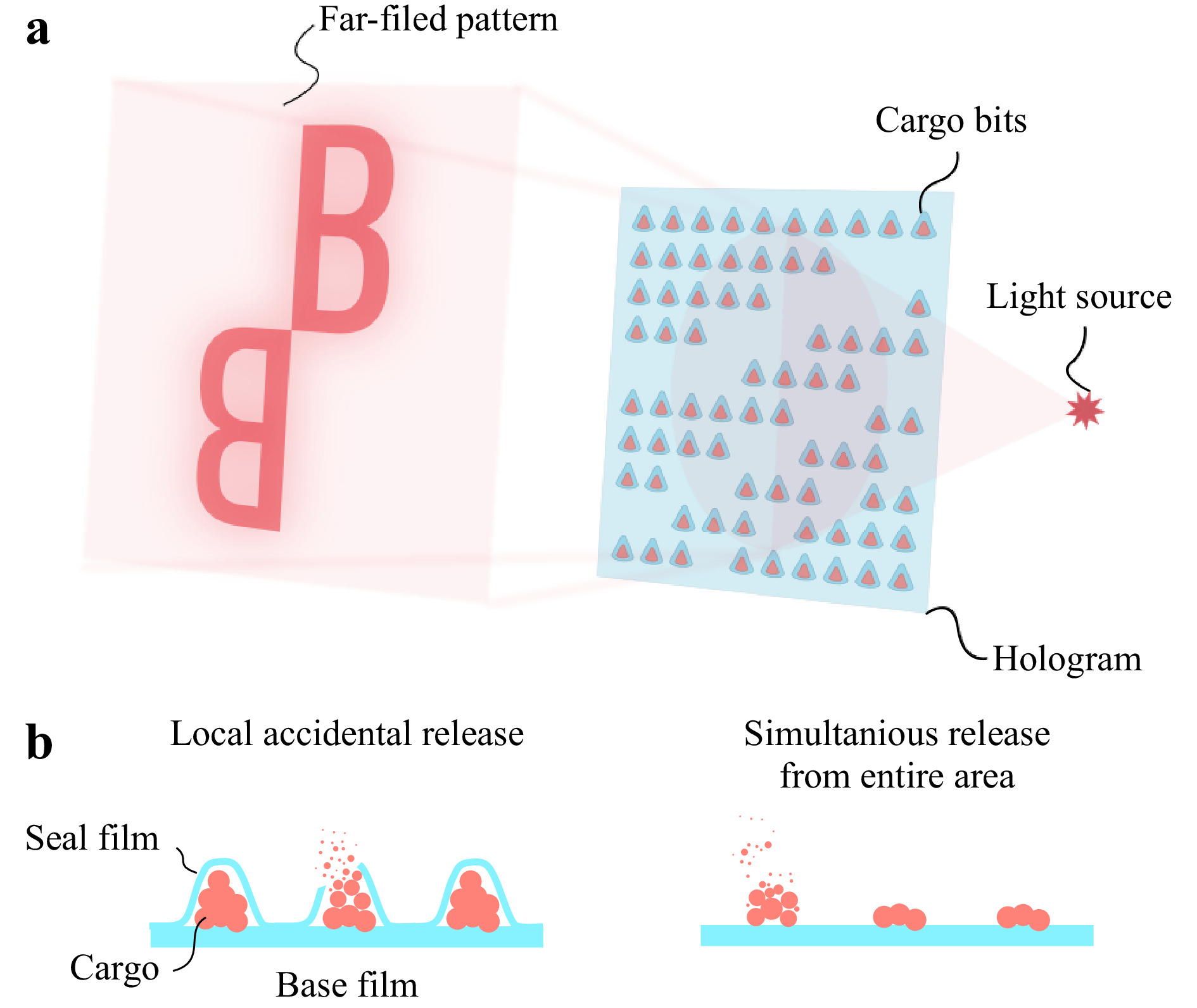
Fig. 1 a Main concept of payload holograms. Opaque cargo bits are placed in a specific order onto the base film to form pre-computed pattern. By illuminating this film with a coherent light source, a desired far-field diffraction pattern could be obtained. b Graphical representation of abovementioned cargo release types.
The first release type was simulated by randomly removing 10% of the initial opaque cargo bits from the hologram unless the desired release mark was reached. The second type was implemented as iterative reduction of overall hologram contrast by 10% unless hitting the same release mark. Root mean square contrast (RMSC) was used to measure the visibility of the far-field diffraction pattern for both types of the release. Results of numerical modeling presented in Fig. 2 clearly shows the difference between described cargo releases schemes.It is a well-known fact that by its nature, each elementary part of the hologram contains the information about the whole scene that is being recorded4. It means that a small uncorrupted part of the initial hologram is sufficient to reconstruct the entire recorded scene with limited contrast. But if the hologram loses its opaqueness uniformly across the whole area at a given rate, it will lead to a faster decay in terms of output image contrast with respect to the remaining payload. Our simulations show that, in principle, up to 70% of the cargo is traceable in the case of local accidental release and up to 40% in the case of simultaneous release from the entire area of the hologram.
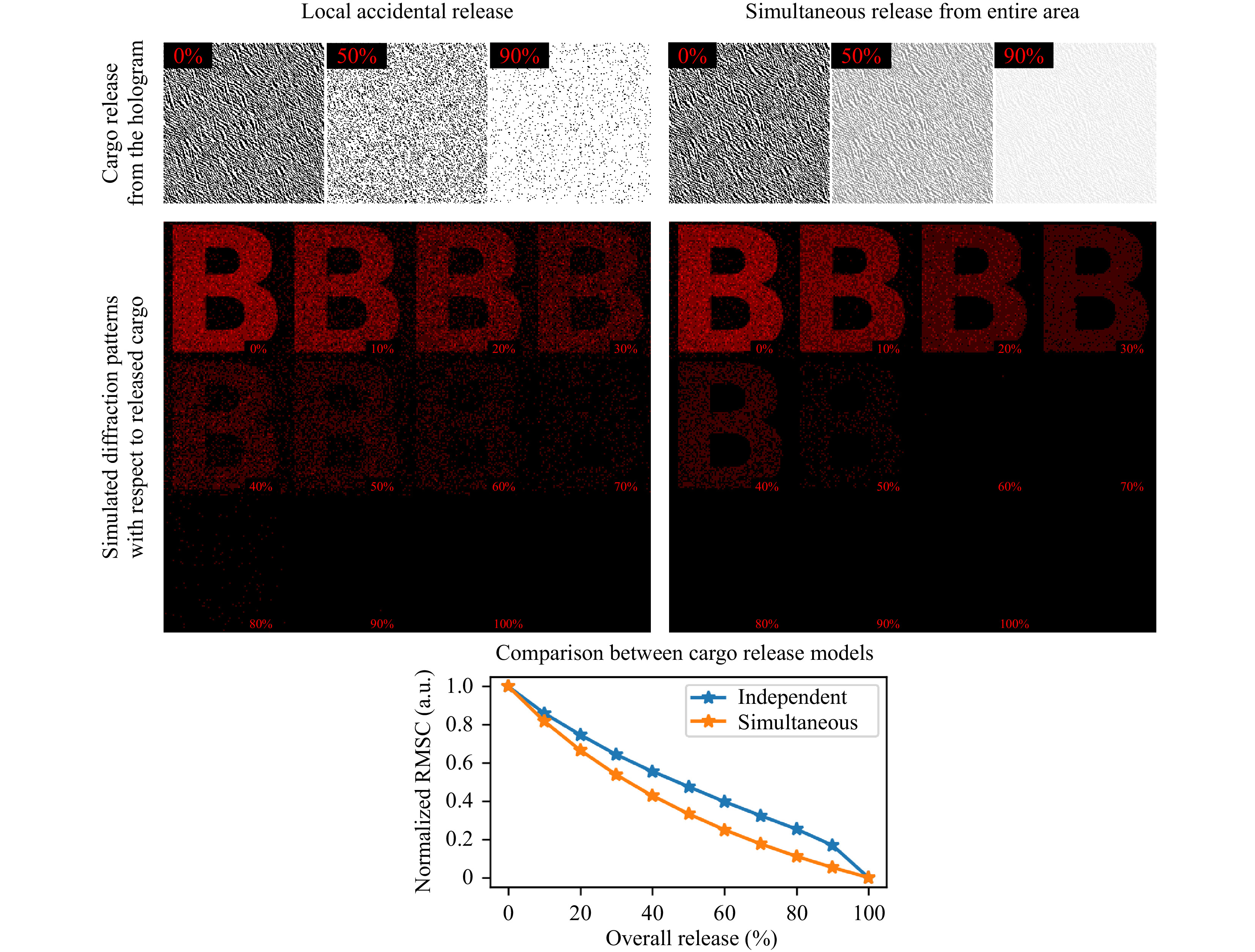
Fig. 2 Computer simulation of different cargo release modes and their effect on the resulted far-field diffraction pattern. The first row shows the appearance of holograms as they release load in various fashions. The local accidental release mode preserves the light-blocking ability of individual cargo bits and their placement, but significantly reduces their overall quantity. Simultaneous release across the whole area of the hologram keeps the total number of cargo bits and their placement unchanged. Instead, the total transparency of the hologram increases. Root mean square contrast of a “B” letter produced in a far-filed zone demonstrates that the local accidental release mode has greater dynamic range when assessing the release of a bioactive substance. Up to 70% of initial cargo could be tracked accurately compared to 40% in the case of simultaneous release from the entire hologram.
-
Binary amplitude-only holograms are manufactured using the direct drug printing method (DDP). This method is designed to work primarily with water-soluble cargos as the most bioactive substances have this property. PDMS mold with wells located according to IFFTA outcome is first loaded with a fine powder of active substance. Most of the dry excess is then removed using a silicone putty knife (SPK). The loaded mold is placed into the freezer at −20°C for 2 minutes. After the mold is taken out of the freezer, a certain amount of condensation would immediately form on its surface, wetting the loaded powder in the well and fully dissolves a small amount of excessive substance between them. Dissolved excess material could be easily removed using the same SPK as before. Wetting of powder that sits in the wells allows it to clunk and form a single bit that can be extracted from the mold. If we neglect the wetting process, the crystals inside the well will be in an unbound state and only a small part of them will be removed from the wells during printing. Highly water-soluble loads like NaCl could form a monocrystalline at this stage.
To extract cargo bits, the mold is rolled onto a 15 µm thick PLA film heated up to 100°C. During the rolling process, viscous and sticky polymer picks up the cargo bits and extracts them from the mold's wells. The result of such rolling is an amplitude-only hologram consisted of a flat polymer film on which opaque cargo bits are located in a certain arrangement. In this study, polylactide acid (PLA, Sigma Aldrich) was used as a base polymer for hologram manufacturing. PLA is biocompatible and biodegradable as well as FDA approved for in vivo application. Still, other polymers with low melting points and/or glass transition temperature like polycaprolactone (PCL) or poly lactic-co-glycolic acid (PLGA) could also be used as base material. The final step is to seal the cargo bits to prevent them from fast dissolving. A flat and soft PDMS sheet is first dipped into the 1% (w/w) solution PLA in chloroform to form a thin (1
$ \mu $ m) film at the PDMS's surface. After that step, flat-coated PDMS is rolled onto the preheated hologram (70°C) to seal exposed cargo bits. The total area of the produced hologram is 1 cm2. The minimum size of the hologram is 2 × 2 mm (limited by the reconstruction beam size), and maximum size 5 × 5 cm (limited by the manufacturing equipment). But the 1 × 1 cm proved to be optimal from the perspective of production simplicity and speed, ease of use, and sufficiency of the loaded substance. Graphical representation of DDP method and manufactured holograms with different cargo is illustrated in Fig. 3. For details of hologram computing and mold manufacturing, please refer to the materials and methods section.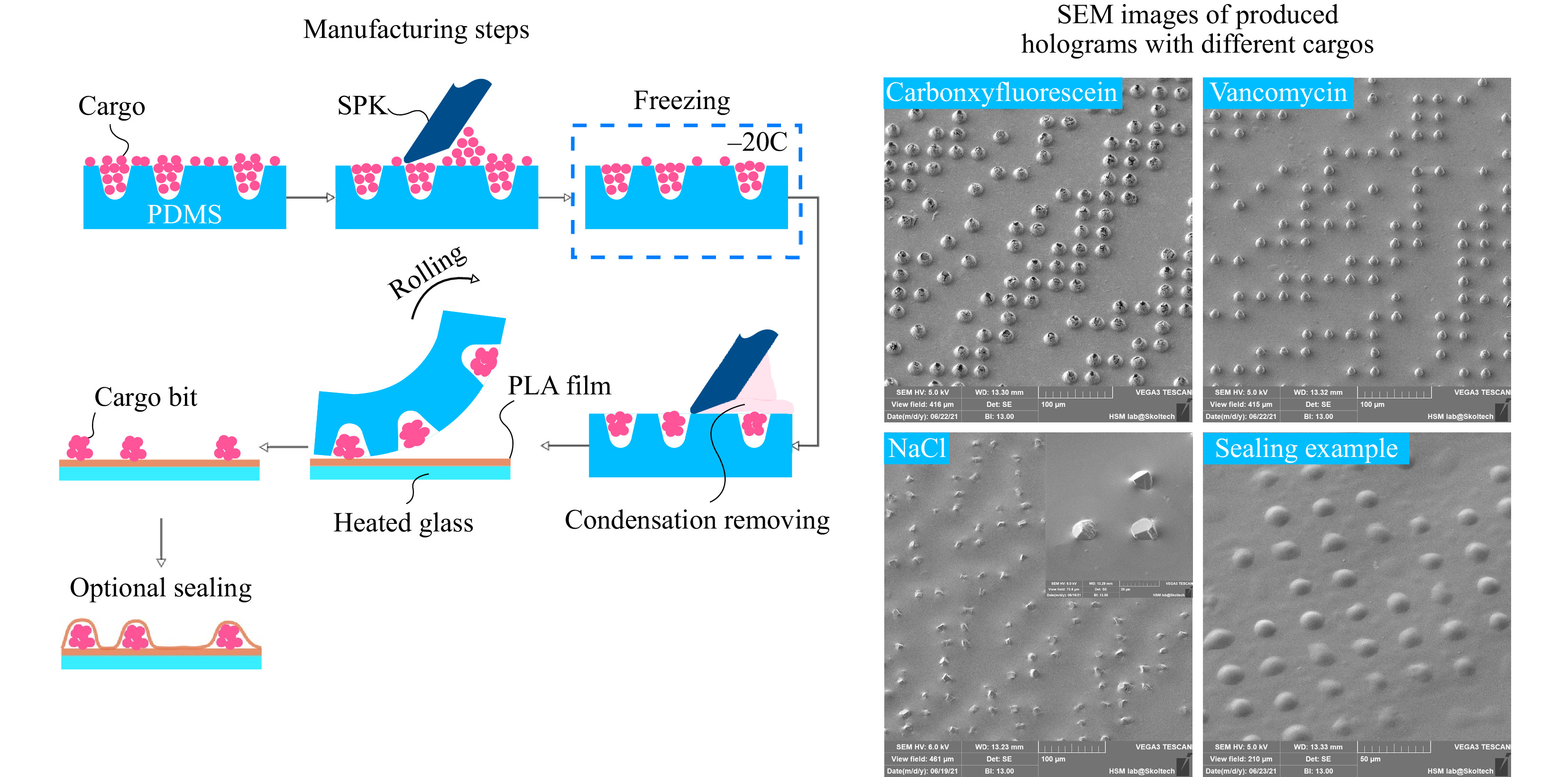
Fig. 3 Schematic representation of the manufacturing process and scanning electron microscopy (SEM) of the produced holograms. The critical steps in the manufacturing process are excess powder removing and freezing. Freezing allows for formation of condensation onto the surface of the PDMS mold. This condensate dissolves the small amount of excess powder left after the initial scurrying process. This thin layer of water solution could be easily removed. The result is almost no redundant powder left in-between the cargo bits that could corrupt the far-field diffraction pattern. The size of a cargo bit is governed by the physical dimensions of the well in the mold and the physical and chemical properties of the loaded powder. Some highly water-soluble cargo like NaCl could produce monocrystalline structures within the mold indentations.
-
To verify the effect of cargo release on the far-field diffraction pattern, a set of holograms were manufactured using the abovementioned DDP method. As for cargo, we chose vancomycin hydrochloride as it is a well water-soluble (100 mg/ml) powder medication generally used to treat a number of bacterial infections29, 30.
Cargo release was conducted by submerging manufactured holograms into 100 ml of water solution of KOH (pH 8.5) at 37°C. It is a known fact that PLA is resistant to acidic environments (pH 3-5) and progressively increases its degradation rate with higher pH values (pH > 7)31, 32. After 24 hours of slow stirring, holograms were extracted from the solution, washed out with deionized water, and dried with compressed air (Fig. 4a).
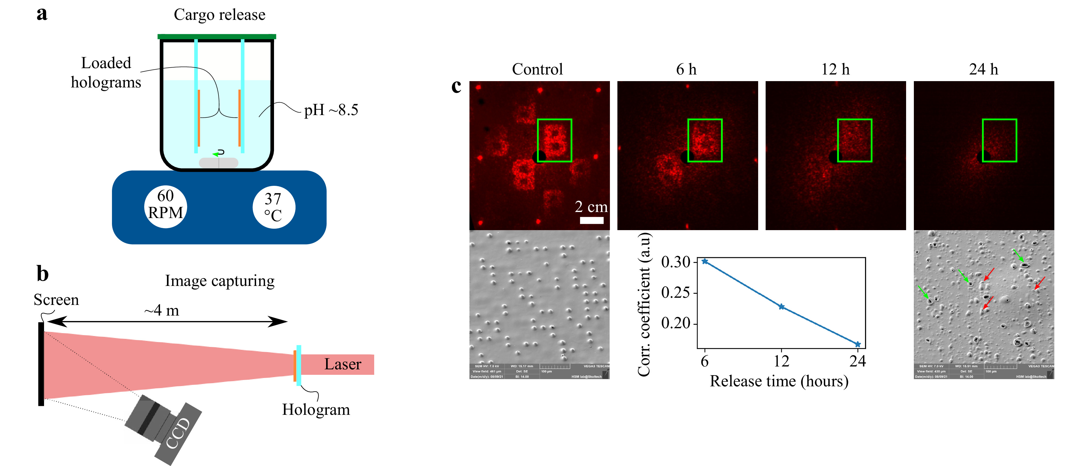
Fig. 4 Experimental setups for a cargo release inducing and b far-field diffraction pattern capturing. Cargo release was performed in a chemical beaker covered with a plastic cap to prevent vapor escaping and keep the total volume of the solution unchanged. In order to uniformly distribute releasing cargo and avoid concentration spikes at the surface of the hologram, slow stirring (60 RPM) was applied. c Far-field diffraction patterns obtained at different timestamps of a cargo release process and corresponding SEM images of hologram's surfaces at the initial state-‘control’ and 24 hours mark since the start point of the release. The correlation coefficient was computed between the diffraction images at different release times within the ROI indicated by the green rectangle.
To check the diffraction patterns before and after cargo release, a simple test setup was arranged. Red diode laser (650 nm, 5 mW) was used as a light source. Black screen was placed at 4 meters from the hologram plane. A black screen was used to dim the diffracted light and increase the apparent contrast of the hologram. The use of a white screen gave a significantly reduced image contrast due to diffuse light scattering within the screen. CCD camera with a 25 mm photo lens was focused onto the screen’s surface (Fig. 4b). As expected, the cargo release process leads to an absence of a far-field diffraction pattern. SEM images of a processed hologram show no cargo bits and presence of large number of pores and craters. This is a consequence of the actively proceeding process of polymer degradation and release of a bioactive substance (Fig. 4c). Experimental results clearly show that the far-field diffraction pattern has the ability to reflect the current state of cargo release process. A clearly distinguishable letter “B” was obtained in the far-field diffraction zone from the initial hologram. At 6 and 12 hours release marks, a gradual decrease in the quality of the diffraction pattern is observed. After 24 hours of the cargo release procedure, no clear diffraction pattern was observed. A slight halo around the zero-order diffraction spot was produced due to the formation of many micro-pores and craters correspondingly marked by the red and green arrows. These micro-pores and craters are formed because of the polymer degradation process. Correlation analysis of acquired diffraction images presented at the graph (Fig. 4c) shows the linear dependence between the correlation coefficient and the release time which is consistent with simulation data, presented in Fig. 2 for the local accidental release mode. In the real case, the release mechanism will tend to lean into the random regime, as the polymer will degrade unpredictably along its surface while being exposed to the inhomogeneous aqueous environment of the living system33. Computer-generated holograms as micro-packaging system opens up a potential opportunity for such devices to be used as a quantitative screening tool for cheap and fast cargo lifespan monitoring.
-
An extension of polymer-based binary holograms to biomedical applications is proposed. We note that there have been recent reports on the DOEs manufacturing out of biopolymers such as PLA34. The noticeable pool of articles dedicated to developing biopolymer drug packaging and delivery microsystems in the form of microchambers placed on a thin film35−39. These works focused on the problems of encapsulation of different types of cargo, especially low molecular-weight ones, while aiming to propose a way for controlling cargo release dynamic in various environments. Making these packaging systems sensitive to external stimuli such as ultrasound waves and high-power laser radiation could be done to accelerate the cargo release process40. However, the effects of the interaction of low-energy laser radiation with array of micro-containers and their ability to form complex diffraction patterns were practically not considered in these works. To our knowledge there is only one article dedicated to that problem, but the authors confined themselves to considering only simple 2D diffraction grating41. We think that there are potential benefits of manufacturing these packaging and delivery polymer microsystems in such a way that they can produce a complex diffraction pattern. This will open a new way of low-cost and efficient monitoring of cargo lifespan. In that case, diffraction efficiency has to be taken into account. Diffraction efficiency is the ratio between the amount of light incident on the hologram and the amount of light which forms diffraction pattern. The main goal of any packaging system is to achieve a high mass of an active substance per area unit while maintaining needed mechanical and chemical properties. In a case of amplitude-only holograms, some parts of the film must be cargo-free to allow light beam passage. The area of these non-payload parts could be minimize by choosing a proper far-field diffraction pattern.
Cargo-bits are small, separated micro-containers. The size of such micro-containers does not exceed several tens of micrometers. They are practically indistinguishable to the naked eye. Of course, it is possible to observe the release of drugs from micro-containers by their optical image. However, for this it is necessary to use an optical system with at least a tenfold magnification. In this case, the field of view of the optical system will not exceed a few square millimeters, which will require scanning of the sample. In contrast, it is quite easy to expand the laser beam to the required size (several square centimeters), which will cover the entire area of the hologram. To observe the diffraction pattern, it will be sufficient to use a simple converging lens with the required focal length, or it is possible to do without it by observing diffraction in the far zone at a distance of several meters from the hologram. These considerations applies to simple cases, such as in-vitro testing of the characteristic release times of antibiotics and other drugs.
Yet, we have showed only analog way to reconstruct the far-field diffraction pattern using the laser. In principle, the same pattern could be obtained numerically from images of the hologram’s surface. For example, a direct reconstruction method via laser will not work if a payload hologram is placed in a highly scattering environment, for example, subcutaneously. However, the recent outstanding progress in the field of optical clearing of biological tissues42−48 makes us confident that payload holograms embedded in the human body will provide the necessary information through skin. Optical clearing techniques significantly reduces the scattering coefficient of a tissue, making it much more transparent within a reasonable amount of time. This virtual transparency window could be used to obtain optical images of the holographic surface. Numerical reconstruction could then performed to compute the far-field diffraction pattern.
In this work, we focused on the amplitude-only binary holograms as they are most suited to perform as cargo- carriers. Amplitude holograms, in general, possess the lowest diffraction efficiency among hologram types. The binary nature forces them to block
$ \approx $ 50% of incoming optical power. Another half is directed to form zero-order and precomputed diffraction patterns correspondingly. It is considered that for amplitude hologram, maximum efficiency is 0.125 (1 is perfectly efficient)49. In our case, the main factor influencing the image quality is the process of infilling stamp’s wells with the cargo. In order for the amplitude hologram to operate near its limit, it is necessary to ensure complete opaqueness of the specific parts of the hologram. Due to the different physical and chemical properties of loaded powders as well as the manual loading process, there is a drift in the opaqueness of cargo-bits along the surface of the hologram. Such drift could be minimized by the development of the automatic cargo-loading machine that ensures uniform infill of the wells as well as utilizing different additives that improve the cohesive properties of the drug to help form a dense light-blocking bit.We have to mention that in the scope of our paper, we dominantly described the fact that conventional holograms could be used as a payload carrier. From this perspective, it is important to achieve a high cargo mass per unit area of the hologram. The geometry of the container (individual diffractive bit) highly affects the quality of produced image50 and it is a trade-off between high useful volume, ability to be loaded with active substances, and acceptable diffraction image quality. As we mentioned above, in the framework of the proposed case, the resulting contrast of the diffraction pattern can be reduced for the sake of increasing the overall drug loading and ease of manufacturing. To achieve the best diffraction output, the cargo bit must be flattened out, and space between them should be eliminated to form light-blocking islands instead of individual dots. However, this will greatly reduce the overall mass of carried load and complicate the manufacturing process as well as disturb the release kinetics.
The impact of various parameters of the system, such as the pitch of the cargo-bits, their size, and film thickness on the holograms, is predictable. For instance, the pitch will affect the scale of the produced diffraction pattern, pitch and size of the cargo-bits will produce a certain surface density, which is directly related to the cargo-mass per unit area of the hologram. The increase in thickness of the sealing film will delay the drug-eluting process in time accordingly. These factors could be used to tune the hologram for the best performance for a specific drug and characteristic release times, but they are not decisive in demonstrating the effect itself.
Theoretically, there is a direct relationship between the cargo-bit distribution in the plane of the hologram and the far-field diffraction pattern. In practice, degradation of the polymer film occurs simultaneously with the drug-eluting process from the cargo bits. Degradation of the polymer film manifests itself in the form of the appearance of a large number of micro-pores of different sizes. These release-associated micro-pores make a significant contribution to the reduction of the contrast of the diffraction pattern and make quantitative cargo release analysis hard to implement. one way around is to first calibrate the degradation process of the base film and its effect on the far-field diffraction pattern and then apply this data to correct the observed precomputed far-field image. A few bold assumptions have to be addressed at this point, namely: polymer degradation is isotropic, and micro-pores morphology is the same at different parts of the films and should not vary much from film to film.
In summary, we have described the method for producing payload holograms. The proposed direct drug printing technique works with water-soluble compounds, but can be adapted to other types of substances if necessary. Numerically and experimentally, we have shown the ability of the diffraction pattern to reflect the amount of cargo remaining in the hologram after a certain amount of time. This unique feature of holographic packaging systems can potentially be used in a wide range of tasks requiring monitoring of the amount of emitted substance. One such application could be microbiotic testing. A visual channel for tracking the amount of released substance can significantly increase the amount of information received during testing and more accurately characterize the effect of an antibiotic.
-
The self-written algorithm in Python code was used to compute computer-generated holograms. To compare the produced diffraction pattern and desired image at each iteration root mean square error was calculated. 256 iterations were done to obtain the final hologram. At the quantization stage
$ \pi $ value was chosen as a single threshold. There is a direct relation between the distribution of binary transmission and the distribution of a binary phase redundancy51. During the computation of the hologram we can consider the binary amplitude hologram as a binary phase transmittance which can only have the complex values$ exp(-i0) = 1 $ and$ exp(-i\pi) = -1 $ . Offsetting these values with a DC-term transforms the resulting binary phase distribution into a binary amplitude distribution between 0 and 152. 128 × 128 pixels images were processed using this Python script. -
A custom Python script was used to simulate the spontaneous local release and continuous dissolving of the cargo bits and their effect on the resulting far-field diffraction pattern. For a quantitative assessment of the visibility of the diffraction pattern, the value of RMSC was calculated by the formula:
$$ RMSC = \sqrt{\frac{1}{MN}\sum\limits_{n = 1}^{N}\sum\limits_{m = 1}^M(I_{n,m}-\overline I)^2} $$ (1) there
$ M, N $ are the number of pixels along the width and height in the region of interest (ROI) which fully enclose the “B” letter,$ I_{n,m} $ and$ \overline I $ are the intensity of a given pixel and average intensity within the ROI correspondingly. In order to evaluate the effect of cargo release in a real experiment, a set of images were taken at different time-points of a drug-eluting process, namely 6, 12 and 24 hours. Correlation coefficient between the initial diffraction pattern (letter “B”) and various stages of release was computed using predefined function$ corrcoef $ from the$ Numpy $ module to quantify the effect of a drug release process. -
In the first stage, the master mold was manufactured out of Kapton polymer using laser ablation method. Cobolt Tor XS (532 nm, 50 µJ, 1.9 ns) was used as a light source. The microscopic objective lens with a numerical aperture of 0.1 focuses laser light onto the Kapton’s surface. 25 laser pulses were used to form one indentation. The pulse repetition rate was set to 1 kHz. To control the spatial position of the master mold, the precise XY stage driven by the custom software was utilized. Fig. 5a highlights the most critical aspects of a custom-made laser ablation system. Resulted indentations are in a cone form with diameter 22 ± 2 µm, height 20 ± 2 µm and angle of 35°. Step between indentations was set to 40 µm. The second step is to replicate Kapton mold features into the PDMS mold, suitable for direct drug printing protocol. Sylgard 184 (DOWSIL) was mixed in the manufacturer prescribed ratio (10:1 w/w), then degassed in the vacuum chamber for 30 minutes and poured onto the surface of the patterned Kapton film. The whole sample was placed into the oven at 100°C for 35 minutes. After the curing process negative PDMS mold (with pillars) was detached from the Kapton film. The third step is PDMS to PDMS casting. This casting cannot be done directly because during the curing process, two PDMS molds will stick together and form a monolithic unit unless a separating layer is used. Negative PDMS mold was dip-coated by the 0.5% (w/w) solution of PLA in chloroform to form a separating film. A new batch of PDMS was mixed using the same protocol as before and poured onto PLA-covered negative PDMS mold. PDMS was cured in the oven at 60°C for 4 hours. Such low curing temperature was chosen to prevent the thermal softening of polylactide film. After curing, two PDMS molds could be easily separated from each over. Resulted positive PDMS mold was used for payload hologram manufacturing.
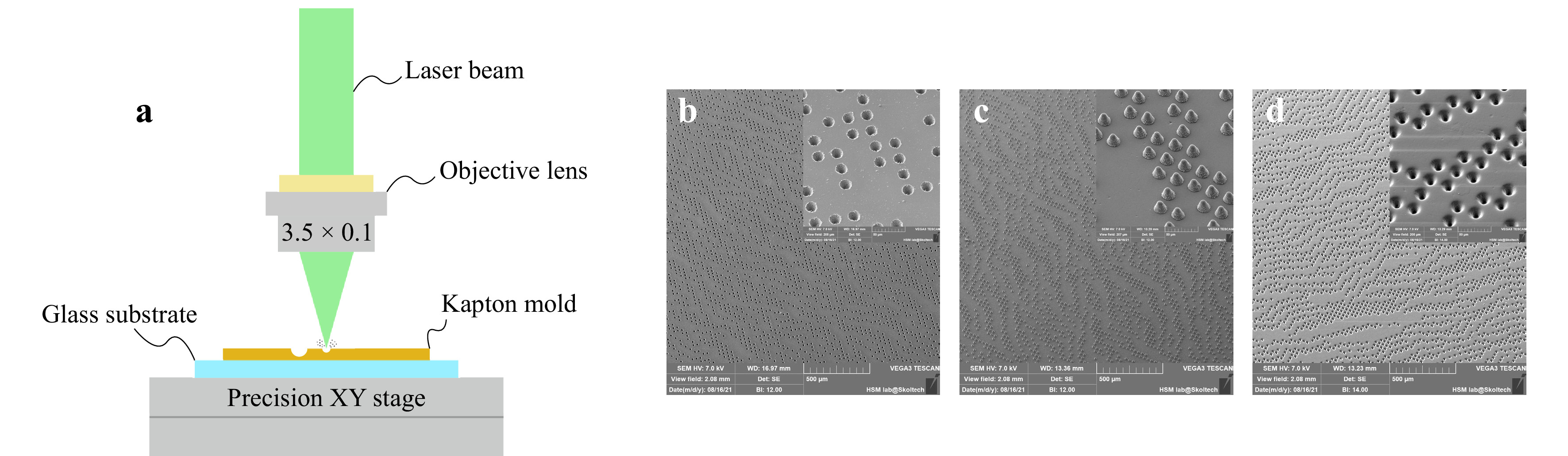
Fig. 5 a The most significant aspects of the experimental laser ablation setup. A collimated laser beam fully illuminates the back entrance pupil of the objective lens to ensure diffraction-limited spot size at the front focal plane. b SEM image of manufactured Kapton master mold. c SEM image of the negative PDMS mold featuring surface quality of produced indentations via laser ablation process. d SEM image of the positive PDMS mold used for direct drug printing method of hologram manufacturing.
-
VVT was supported by the grant No. 13.2251.21.0009 of the Ministry of Science and Higher Education of the Russian Federation (agreement No. 075-15-2021-942); the work was also partly supported by the Siberian State Medical University’s development program Priority 2030.


 DownLoad: