


-
Vortex and vector terahertz (THz) beams1 became quite a hot topic in the last decade due to their importance for wireless data transfer multiplexing2-4, imaging5, including in highly scattering and absorbing media6, ultrafast current and (de)magnetisation processes probing7 and even waveguide electron acceleration by a longitudinal polarisation mode8,9. Despite the growing application-driven demand for shaped vector and vortex beams10, especially for ultrafast THz radiation, the amount of approaches to formation and generation, as well as the number of techniques to conveniently assess and characterise such beams is rather limited since they were mainly adopted from the visible range11.
In the first paper12 of this paired set we provided a comprehensive review of the perspectives for vector and vortex THz beam shaping with geometric phase effect13. We have outlined two main approaches characterised by the different order of the main elements in the shaper. Possible variants for the arrangement of polarising components in the modulator for the formation of a circularly, linearly polarised vortex and cylindrical vector beams are shown in Fig. 1. In general, an overall number of degrees of freedom and achievable states are much greater14. Type I shaping approach shown in the first column of Fig. 1 consists in an action of a q-plate on a circularly polarised THz beam after it has passed a quarter-wave plate (QWP), while the type II scheme features the direct action of the q-plate on the linearly polarised incoming beam. As a result, the top row presents the concept of the singular beams formation, namely the circularly polarised vortex for type I15, and radially (or azimuthally, depending on the incoming beam polarisation) polarised vector beam with a flat phase surface for type II of the shaping approach. If all the components demonstrate achromaticity in the overlapping spectral regions, THz broadband uniformly topologically charged (BUTCH) beams6 within the overlap of achromaticity of all shaper elements, will be eventually formed.
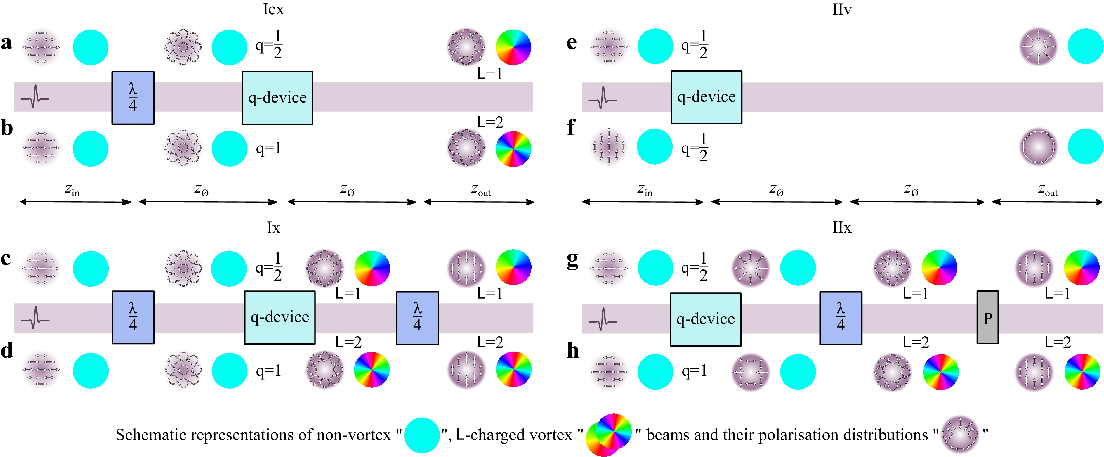
Fig. 1 Two main scheme types (I and II) for THz vector (v) and vortex (cx, x) beam shaping, respectively.
$ \mathsf{L}=\pm 1 $ a, c, g and$ \mathsf{L}=\pm 2 $ b, d, h charged beam with circular cx a, b, and linear x c, d, g, h polarisation, respectively; cylindrical v beams with radial e and azimuthal f polarisations respectively.$ z_{{\rm{in}}} $ ,$ z_{\varnothing} $ and$ z_{{\rm{out}}} $ are the distances from the Gaussian beam waist to the modulator, between the devices, and from the modulator to the receiver, respectively. The notations of polarisation elements are used:$ \lambda/4 $ is a QWP; P denotes a linear polariser.Let us look more carefully into the process of vector and vortex beam formation, illustrated on Fig. 1. The incident linearly polarised pulsed THz field passes through various combinations of optical components shown in the corresponding schemes. Beam structure transformation schematically displayed with round insets. Due to the presence of various polarisation components in vector beams and the complexity of unambiguous representation of the corresponding them phase distribution we designate the absence and presence of transverse energy circulation by cyan and rainbow circles, respectively. According to the type I (Fig. 1a, b), a circularly polarised pulsed beam from a QWP, incident normally to the surface of a q-plate, is converted into a ‘cx’–type beam (notation ‘cx’ is used as a reference to ‘Circularly polarised vorteX’) with opposite circularity and projections of orbital angular momenta (OAM) in the direction of propagation
$ z $ :$ L_{z}=\pm 1 $ and$ L_{z}=\pm 2 $ , depending on a q-plate value, and axial phase singularity. To make the beam linearly polarised again, another QWP is used after the q-plate on the scheme Ix (Fig. 1c, d). Note that scheme Ix supports another way of circularly-to-linearly polarised vortex conversion which may be done using a linear polariser instead of the second QWP. But in this case, a part of the energy corresponding to the orthogonal polarisation component will be cut off, which will lead to greater losses. The second type of shaping, designated as IIv (‘v’ denotes ‘Vector’) allows one to convert a linearly polarised non-singular beam to a vector beam with radial or azimuthal polarisation (Fig. 1e, f). To perform vector-to-vortex beam conversion carrying helical wavefront, formed vector beams must be further directed on the QWP to obtain the topological charge (Fig. 1g, h, the appearance of transverse energy circulation in the linear polarised component of the vector beams after its passage through the QWP is shown by a rainbow circular insets, the conversion to linear polarisation by a polariser P is also illustrated) in accordance with IIx scenario. Such configuration of elements still was not directly validated in the THz frequency range, but was used to prepare vortex pulses involved in the subsequent active generation of vortex THz beams16,17.A vast variety of polarisation components can be used as constituents of the beam shapers, and we reviewed a state-of-the-art of these components in the first paper12 of this paired set. Detailed analysis of achromatic components revealed numerous limitations of their applicability, mostly due to non-perfect achromaticity and geometric limitations. Therefore, when designing a beam shaper, before embedding any component, it is necessary to take into account all the specifics of its operation. The optimal tool for this task is THz pulse time-domain holography (PTDH)18-20, since this technique provides the ultimate opportunity to track the dynamics of all characteristics of the broadband THz field in the spatial, temporal, spectral and angular coordinates during its propagation, both in free space and in optical systems with known characteristics6,21-23.
THz PTDH is a modern technique that includes extensive experimental capabilities for the physical measurement of broadband THz wavefronts with their subsequent time-reversal and aimed at solutions of a wide spectrum of practical tasks. In addition, it also can be exploited as an effective ‘virtual instrument’ to predict specific properties of ultrafast pulses after their propagation through or reflectance from the specific elements/components/samples. In this paper, we will pay attention to opportunities for numerical wavefront shapers design, while the description of experimental works20,23,24, and manufacturing of the measurement unit based on 3D-models in open-source codes25,26, remains beyond the scope of our current consideration.
Numerical research using virtual instruments is currently gaining popularity for solving various technical problems. Virtual instruments are already being effectively used in metrology for measuring the uncertainty estimation in coordinate measuring machines27-29, microscopic 3D surface measurements30,31. Numerical methods are also in demand in such tasks as beam shaping32 and the design and prediction of optical functionalities of various optical components, such as metasurfaces33. The main condition that guarantees success when using numerical tools is the presence of an accurate validated physical model of the simulated process. In the tasks of developing elements to form an electromagnetic field with desired structure, as a rule, methods of classical electrodynamics are used to estimate an impact of variable element parameters. However, such approaches as finite-difference time-domain (FDTD) are quite resource-intensive, and their application is not always justified. In this paper, we combined the Jones matrix formalism with the mathematical model of the THz PTDH method based on the scalar theory of diffraction, describing the propagation of the orthogonal polarisation components of the ultrafast THz field. The resulting technique allows tuning the beam shaping components to ensure maximally possible matching between the characteristics of formed and desired beam.
In this part of our paired set of papers, we consider some examples of THz vortex beam formation in details, and demonstrate the capabilities of a THz PTDH in assessment of the impact of the designed achromatic modulator's components on the incoming broadband THz field. Using THz PTDH, we visualise the spatio-temporal and spatio-spectral evolution of vectorial ultra-broadband THz wavefields upon their process of diffraction in type Ix and Icx modulators and in free space at their output. This technique allows for taking into account the transformation of characteristics of these wavefields by the optical elements and further optimisation of the mentioned wavefront modulators in sequential calculations. We reveal the capabilities of the proposed technique by providing the design of beam shapers that introduce not only a positive but also a negative uniform topological charge in a certain limited range of the THz spectrum and show the spectral and temporal characteristics of the formed beams.
-
This section describes the applicability of THz PTDH for numerical and experimental studies of achromatic vortex beam modulators. We will demonstrate the capabilities of the PTDH on the example of multilayer quartz wave plates with a certain achromaticity in wavefront retardation in the broad THz range, which have been mentioned in the first paper12 of this paired set. However, we note that we propose our technique not only as a method for the quartz plate-based beam shapers design, but for any component-based beam shapers, with any known spectral amplitude and phase characteristics, either full or partially achromatic, such as those reviewed in the first paper of this paired set12. The eligible components can exploit the total internal reflection principle, liquid crystals, metasurfaces and on others principles (such as twisted fibers34, if they are adapted for the THz range). The only necessary condition for the element to be taken into account is the spectral dependence of its action on the incoming beam presented either in the form of spatial amplitude and phase mask, or, for polarising elements, in the form of Jones or Müller matrices.
-
In the framework of the Jones formalism, linearly polarised along the
$ x $ -axis broadband THz field propagating orthogonal to the director axis of a birefringent medium can be represented by the following Jones vector:$$ {\bf{G}}_{{\rm{in}}}(x,y,\nu) = \left( \begin{array}{l} {G_{{\rm{in}}_x}(x,y,\nu)}\\ {0} \end{array} \right) $$ (1) and the action of an optical element onto the electric field vector is given by the Jones matrix.
$$ {J(\nu)} = \left( {\begin{array}{*{20}{c}} A(\nu)&B(\nu)\\ C(\nu)&D(\nu) \end{array}} \right) $$ (2) resulting in a certain frequency-dependent change of the broadband THz field:
$$ \left( \begin{array}{l} {G_{{\rm{out}}_x}(x,y,\nu)}\\ {G_{{\rm{out}}_y}(x,y,\nu)} \end{array} \right) = \left( {\begin{array}{*{10}{c}} A(\nu) & B(\nu)\\ C(\nu) & D(\nu) \end{array}} \right) \cdot \left( \begin{array}{l} {G_{{\rm{in}}_x}(x,y,\nu)}\\ {0} \end{array} \right) $$ (3) One of the simplest and most developed approaches to design of achromatic wave plates essential for broadband THz beam manipulation is to stack
$ N $ plates of birefringent material and adjust their thicknesses and orientation to even out the introduced phase retardation of the ordinary wave relative to the extraordinary wave for all spectral components of interest (Fig. 2a). The phase delay introduced by a single$ j- $ th birefringent layer, coorientated with the incoming wave polarisation, can be written as: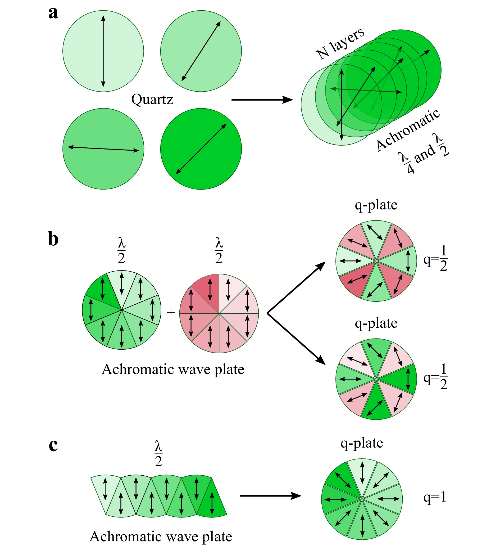
Fig. 2 Layouts for achromatic wave plate a, and q-plates with
$ q=1/2 $ b and$ q=1 $ c.$$ \begin{array}{*{20}{l}} \delta_{j}(\nu,h_j) = {\varphi _x} - {\varphi _y} = 2\pi h_j\left( {{n_{{\rm{e}}}} - {n_o}} \right)\dfrac{{\nu}}{c} \end{array} $$ (4) where
$ n_{\rm{o}} $ and$ n_{\rm{e}} $ are refractive indices for ordinary and extraordinary waves, respectively;$ h_j $ is the thickness of the$ j $ -th plate.The influence of each birefringent layer acting as a wave plate in the multilayer achromatic plate on transmitted broadband radiation can be described by the frequency-dependent Jones matrix35:
$$ \begin{array}{*{20}{l}} {J_j(\nu)} = \left( {\begin{array}{*{20}{c}} A_j(\nu)&B_j(\nu)\\ -B_j^*(\nu)&A_j^*(\nu) \end{array}} \right) \end{array} $$ (5) where
$$ \left\{\begin{array}{l} A_{j}(v)=\cos \left(\dfrac{\delta_{j}(v)}{2}\right)+i \cos \left(2 \theta_{j}\right) \cdot \sin \left(\dfrac{\delta_{j}(v)}{2}\right) \\ B_{j}(v)=i \sin \left(2 \theta_{j}\right) \cdot \sin \left(\dfrac{\delta_{j}(v)}{2}\right) \end{array}\right.$$ (6) Here
$ \theta $ is the angle of the$ j $ -th layer optical axis orientation with respect to the$ x $ axis. The resulting matrix of the composite wave plate can be obtained by multiplying the matrices$ J_j $ of each layer in reverse order:$$ J_{a} = \prod\limits_{j=N}^{1}J_j $$ (7) Adjusting the orientation
$ \theta_j $ and thickness$ h_j $ , it is possible to provide any relatively uniform achromatic phase delay$ \delta_a(\nu)\approx{\rm{constant}} $ in a multilayer structure for a relatively broad frequency range35, thus allowing for relatively achromatic wave plate operation of the resulting stack. If the target wave plate is a QWP, the necessary retardation is$ \delta_a ={\pi }/{2} $ in the designed achromaticity interval. Similarly, for the half-wave plate (HWP) the target delay will be$ \delta_a ={\pi} $ .For the designed assembly to work as a q-plate, the director of an HWP must be sequentially changed in a circular roundabout of the optical axis. In practise, this is usually achieved by splitting the wave plate into a finite number of sectors. Often, upon manufacture, it is not always possible to reproduce a smooth rotation of the optical axis of a q-plate. In such cases, q-plate is divided into a discrete number of sectors, each having its own discrete angle
$ \psi $ of the optical axis following the above-mentioned rule. This approach allows the introduction of a constant phase delay in each segment$ \Delta \varphi =\pm ({2q\psi }/{M}) $ , where$ M $ is a number of segments selected in such a way that the value of the resulting phase shift throughout the entire plate is equal to$ \varphi = 2\pi \mathsf{L} $ , where$ \mathsf{L} $ is a vortex topological charge. In this case, the dependence$ \theta \left( \psi \right) $ on each m-th segment will take the form of a piecewise smooth function, representable by a set of functions in the following form:$$ \begin{array}{*{20}{l}} \Phi \left( \psi \right)=\left\{ \begin{aligned} qm\Delta ,\;\; &\psi \in \left( m\Delta , \left( m+1 \right)\Delta \right) \\ 0, \;\; &\psi \notin \left( m\Delta , \left( m+1 \right)\Delta \right) \\ \end{aligned} \right. \end{array} $$ (8) where
$ \Delta ={2\pi }/{M} $ is the angular measure of each sector,$m=0,1,2,...M-1 $ . Thus, the resulting director’s rotation with respect to the plate can be written as the following sum:$$ \begin{array}{*{20}{l}} \theta \left( \psi \right)=\displaystyle\sum\limits_{m=0}^{M-1}{\Phi \left( \psi \right)} \end{array} $$ (9) Further extrapolating the idea of designing multilayered wave plates introducing spectrally-isotropic response for THz pulses, we propose the design of an achromatic q-plate created from eight sectors of a quartz birefringent achromatic HWP (
$ \delta =\pi $ ) as shown in Fig. 3c in the first paper12 of this paired set. Being located in the type I beam shaping scheme (Figs. 1a−d) this plate will introduce uniform topological charge across its whole operational spectrum, and the beam after passing such wave plate becomes a BUTCH beam. Schematic examples of such 8-sector q-plates for$ \mathsf{L}=1 $ and$ \mathsf{L}=2 $ topological charges and the corresponding cuts of the parent HWPs are shown in Fig. 2b, c.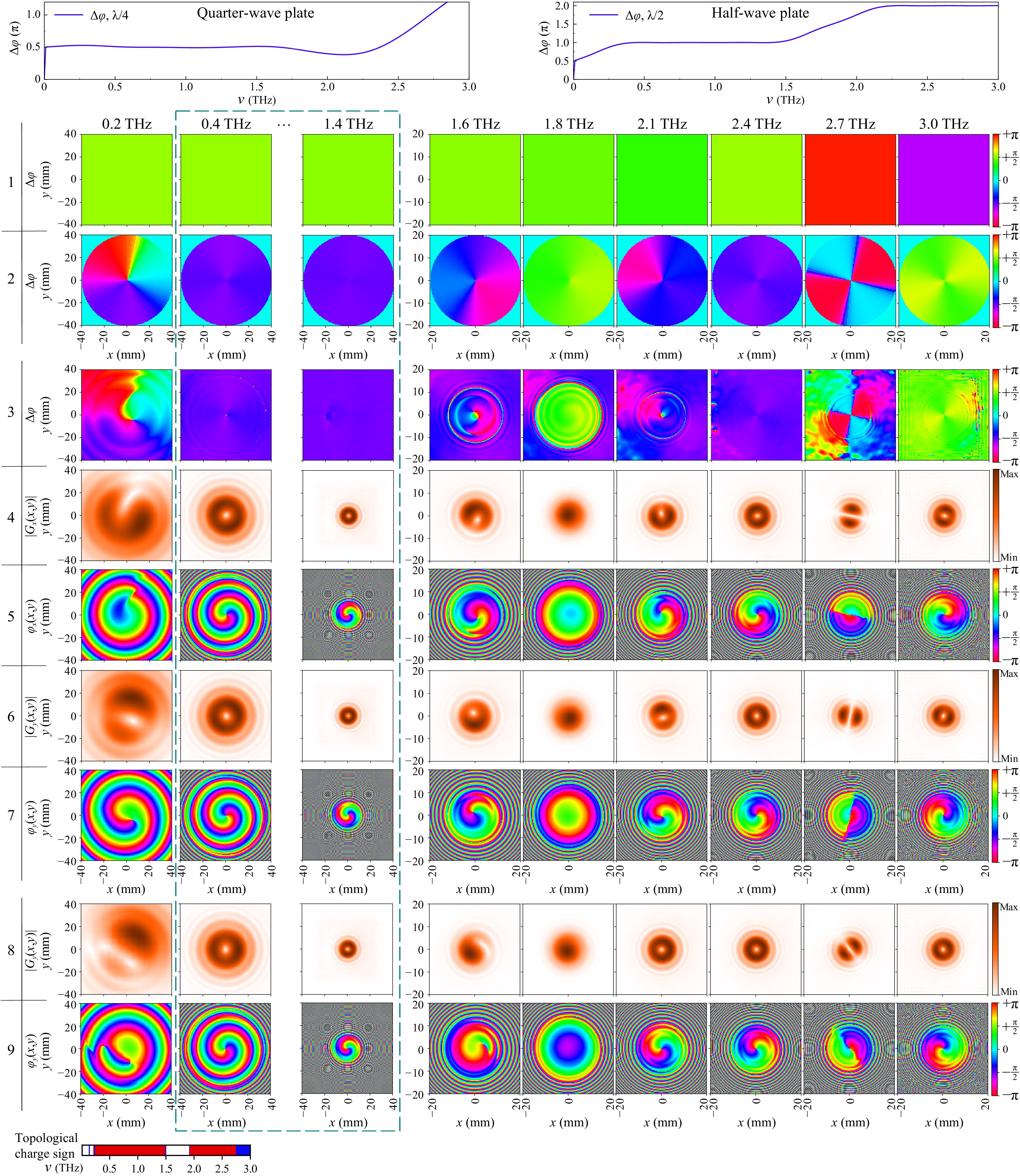
Fig. 3 Frequency-resolved characteristics of the THz field formed by sets of achromatic components arranged in Icx (rows 1-7) and Ix (rows 1-2, 8-9). Rows 1-3 are the phase differences
$ \Delta \varphi $ between transverse THz field polarisation components, directly after the propagation QWP (row 1), q-plate (row 2) and in the detection plane$ z_{\sum} $ for Icx-type (row 3); rows 4-9 are spectral density modulus (amplitude) (rows 4, 6 and 8) and the phase (rows 5, 7 and 9) images in the detection plane$ z_{\sum} $ for Icx- (rows 4, 5 for$ x $ - and 6, 7 for$ y $ - polarisation) and Ix- (rows 8-9) types. Top insets: the dependencies of the phase shift$ \Delta\varphi $ on the THz radiation frequency introduced by the QWP (left graph) and HWP (right graph). -
Our group designed 7-layer achromatic wave plates (Fig. 2) providing a reasonably flat response in the frequency range 0.4 – 1.4 THz. To calculate design, we took the data for refractive indices used in the Ref.35, and minimised the following criteria for QWP and HWP correspondingly:
$$ \begin{aligned}&\displaystyle\sum_{\nu=0.4 {\rm{ THz}}}^{1.4 {\rm{ THz}}}{\|\delta(\nu)-\frac{\pi}{2}\| + \|\Delta\varphi(\nu)-\frac{\pi}{2}\| + \|\varepsilon(\nu)-1\|} \\&\displaystyle\sum_{\nu=0.4 {\rm{ THz}}}^{1.4 {\rm{ THz}}}{\|\delta(\nu)-\pi\| + \|\Delta\varphi(\nu)-\pi\| + \|\varepsilon(\nu)\|} \end{aligned} $$ (10) Here
$$ \begin{aligned} &\delta(\nu) = 2\tan^{-1}\sqrt{\dfrac{\left|{\rm{Im}}\; A\right|^2+\left|{\rm{Im}}\; B\right|^2}{\left|{\rm{Re}}\; A\right|^2+\left|{\rm{Re}}\; B\right|^2}}, \; \Delta\varphi=\varphi_y-\varphi_x, {\rm{and}} \\ &\varepsilon = \frac{|G_x|^2 + |G_y|^2 - \sqrt{|G_x|^4 + |G_y|^4 + 2|G_x|^2|G_y|^2 \cos{2\Delta \varphi}}}{|G_x|^2 + |G_y|^2 + \sqrt{|G_x|^4 + |G_y|^4 + 2|G_x|^2|G_y|^2\cos{2\Delta\varphi}}}. \label{eq:epsilon} \end{aligned} $$ are the chromatic retardation, direct phase delay and the ellipticity, correspondingly.
-
To track in detail the changes that occur in the spatial frequency structure of the broadband THz vector and/or vortex field, generated by the combination of wave plates and q-plates, introduced in Figs. 1a−d, we will use the THz PTDH for a stepwise numerical simulation of the wavefront propagation process36, and supplement it with the effect of the wave plates.
Ideally, all beam shaping components must be stacked together to minimise diffraction and Fresnel losses. However, in practise, it becomes a difficult task. Thus, to avoid superimposition of the Fresnel reflections of the time-domain signal from the wave plate-air interfaces, all components of the beam shaper must be separated by a distance
$ z_{\varnothing} > 0.5\cdot c \cdot T_{w} $ , where$ T_{w} $ is the time interval of observation.In PTDH, the equations of scalar diffraction theory are solved for each spectral and polarisation component (see Eqs. (1−3), (6−11) in work6, Eqs. (1−10) in paper37). While detailed description of the method can be found elsewhere22,37-39, for the sake of simplicity, the change of the broadband scalar field during propagation to the optical path
$ z $ can be denoted with propagation operator$ {\cal{F}}_z $ . It should be noted that in the propagation process from the source to the first modulator element, the broadband THz field is noticeably transformed23, and therefore the evolution of the field at the distance$ z_{{\rm{in}}} $ must also be taken into account by applying the operator$ {\cal{F}}_{z_{{\rm{in}}}} $ to the field at the source to obtain the vector field in the input plane of the first modulator element:$$ \begin{array}{*{20}{l}} {\bf{G}}_{{\rm{in}}}(x,y,z_{{\rm{in}}},\nu) = {\cal{F}}_{z_{{\rm{in}}}} \left( {\bf{G}}_{{\rm{0}}}(x,y,0,\nu)\right) \end{array} $$ (11) Then, the process of propagation of the THz incoming vector field
$ {\bf{G}}_{{\rm{in}}}(x,y,z_{{\rm{in}}},\nu) $ through the Icx-type beam shaper (shown in Fig. 1a) can be described as:$$ \begin{array}{*{20}{l}} \begin{split} {\bf{G}}_{{\rm{out}}}&(x,y,z_{_{\sum}},\nu) = \\ &= {\cal{F}}_{z_{{\rm{out}}}+z_{{\rm{Icx}}}+z_{\varnothing}}\left(J_{q}{\cal{F}}_{z_{\varnothing}}\left( J_{\frac{\lambda }{4}}{\bf{G}}_{{\rm{in}}}(x,y,z_{{\rm{in}}},\nu)\right)\right) \end{split} \end{array} $$ (12) Here,
$ J_q $ and$ J_{{\lambda }/{4}} $ are the Jones matrices of q-plate and QWP, correspondingly;$ z_{_{\sum}} = z_{{\rm{out}}} + z_{{\rm{Icx}}} + 2z_{\varnothing} + z_{{\rm{in}}} $ is the aggregate optical beam path from THz source to the observation plane;$ z_{\varnothing} $ is the distance between wave plates in the modulator;$ z_{{\rm{Icx}}} = h_{{\lambda }/{4}}/n_{\rm{e}} + h_q/n_{\rm{e}} $ is the optical beam path inside achromatic wave plates. For simplicity, we take into account the optical beam path in the wave plates after the matrix transformation of the field, assuming that the change in the structure of the beam when propagating inside these wave plates is insignificant in comparison with the aggregate optical beam path ($ z_{{\rm{Icx}}} \ll z_{\sum} $ ).Similarly, for the type IIx beam shaper, the field at the output can be written as:
$$ \begin{array}{*{20}{l}} \begin{split} {\bf{G}}&_{{\rm{out}}}(x,y,z_{_{\sum}},\nu) =\\ &= {\cal{F}}_{z_{{\rm{out}}}+z_{{\rm{IIx}}}}\left(J_{p}{\cal{F}}_{z_{\varnothing}}\left(J_{\frac{\lambda }{4}}{\cal{F}}_{z_{\varnothing}}\left( J_q{\bf{G}}_{{\rm{in}}}(x,y,z_{{\rm{in}}},\nu)\right)\right)\right) \end{split} \end{array} $$ (13) with
$ z_{{\rm{IIx}}} = h_q/n_{\rm{e}} + h_{{\lambda }/{4}}/n_{\rm{e}} + z_p $ the optical thickness of type IIx modulator components. Here$ z_p \rightarrow 0 $ is the polariser optical thickness and$ J_{p} $ is the Jones matrix of the linear polariser.Thus, by varying the distance
$ z_{{\rm{out}}} $ , one can numerically track the evolution of the formed complexly structured beams during their further propagation in free space. These possibilities of numerical research, after the beam shaper manufacturing, can be supplemented by the potential of physical experimental research. Indeed, having an electro-optical detection module40 available or fabricating it using additive manufacturing methods based on open source 3D models25,26, it is possible to record the spatio-temporal dependence of the THz field strength in the diffraction zone. Then, by excluding a possible measurement system response (e.g. excluding noise37,41), one can perform time-reversal of broadband THz wavefront and track the reverse dynamics of the pulse propagation, as was repeatedly implemented20,23,42. -
When designing beam modulators, a number of important features should be taken into account. There are 4 factors that should be considered: (i) the limited spectral bandwidth of anisotropic phase delay in broadband achromatic wave plates imposes a restriction on the spectral interval at which the homogeneous topological charge is formed; (ii) the spectrally-resolved ellipticity of broadband polarised radiation, which characterises achromatic QWPs in the composition of the modulator affects the azimuthal homogeneity in the spectrally-resolved amplitude distribution of the formed beam; (iii) q-plate introduces the spiral phase shift in the modal distribution of input radiation which leads to the appearance of a singular point, which, in turn, is the cause of an additional diffraction perturbation; (iv) the segmented q-plate with eight sectors forms the non-smooth phase distribution with eight phase steps, the traces of which, during the wavefront propagation, also appear in amplitude.
-
This section presents the results of numerical simulations of the BUTCH beam-shaping process using the THz PTDH method. For the numerical experiment, the following parameters were set: refractive indices of crystalline quartz
$ n_{\rm{o}}=2.116 $ ,$ n_{\rm{e}}=2.165 $ , the thicknesses of multilayer wave plates are$ h_{{\lambda }/{4}} = 17.7 $ mm and$ h_q = 23.0 $ mm. The first QWP was placed$ z_{{\rm{in}}}=180 $ mm after the incoming plane, optical distance between the plates in the beam shaper$ z_{\varnothing}=15 $ mm,$ z_{_{\sum}} = 350 $ mm. The optical beam paths$ z_{{\rm{type}}} $ for various scheme types (i.e.$ z_{{\rm{Icx}}} $ and$ z_{{\rm{Ix}}} $ ) were taken into account:$ z_{{\rm{out}}} + z_{{\rm{type}}}=140 $ mm. The other parameters are: transverse spatial grid size$ N_x = N_y= 128 $ pixels, physical size of transverse spatial grid grid$ D_x=D_y={\rm{40, 80,\; and\; 120}} $ mm, temporal grid size$ N_t=2048 $ points, temporal window$ T_{w}=100 $ ps, THz pulse duration$ \tau=0.3 $ ps (the corresponding temporal THz spectrum was in the$ 0.01-3 $ THz range with a central frequency of 0.75 THz). The initial THz field is modelled as the Gaussian beam with the waist parameter$ \rho_0= 4.7 $ mm43, which is appropriate for the beam size of the THz source (TERA-AX module by Avesta Project Ltd.). -
Various designs of achromatic modulator components were prepared and numerically examined in a virtual assembly to gain insight into the properties of the formed vortex beam. Fig. 3 represents the characteristics of calculated linear and circular polarised vortex beams formed by the best set of achromatic components.
Let us consider the obtained results in more detail. Meticulous handling of all the details that are usually ignored reveals new features for accurate beam shapers design. The first 3 rows of Fig. 3 show the phase difference of the transverse spatial distributions
$ \Delta \varphi = \varphi_y\left(x,y\right)- \varphi_x\left(x,y\right) $ for the orthogonal field components after the first QWP (row 1), the q-plate (row 2) (Supplementary S1.mp4). The phase maps shown in the first row are in accordance with the QWP phase delay plot presented immediately above in this figure. Then, we can observe the formation and evolution of the vortex structure as the THz field passes through the next modulator element, namely, q-plate. In row 2 it can be seen that in the frequency range 0.4 – 1.4 THz, the spatial distribution of the phase difference between the$ y $ - and$ x $ -polarisation components is quite uniform, and their values themselves correspond to$ -\pi/2 $ . These homogeneous relationships in the phase delay induced by the first two modulator elements are also maintained in the detection zone (row 3).Rows 4−7 of Fig. 3 demonstrate the spatial transverse distributions of the electric field modulus
$ \left|G_x\left(x,y\right)\right| $ and$ \left|G_y\left(x,y\right)\right| $ for both$ x $ and$ y $ polarisations of the denoted spectral components and their corresponding phase distributions$ \varphi_x\left(x,y\right) $ and$ \varphi_y\left(x,y\right) $ (Supplementary S2.mp4). On the spectral components that fall within the indicated range of achromaticity of the beam shaper elements, a donut-shaped distribution of the field amplitude is expectedly observed (rows 4 and 6), and spatial phase distributions of the field at these frequencies, shown in rows 5 and 7, clearly reveal vortex structure rotated by$ -\pi/2 $ with respect to each other. Thus, we can confirm that the designed achromatic QWP and the segmented q-plate, assembled from engineered achromatic HWPs, make a perfect circularly polarised THz BUTCH beam shaper. All these results witness the operability of the scheme of Icx-type.To obtain a linearly polarised THz BUTCH beam, the circularly polarised BUTCH beam described above is sent through another achromatic QWP, for Ix-type shaping, where the circular polarisation is converted to linear one in the operational range of QWP, depending on its orientation, as outlined in Fig. 1c and discussed above. Row 8 shows the modulus
$ \left|G_y\left(x,y\right)\right| $ , while row 9 depicts the phase$ \varphi_y\left(x,y\right) $ of the$ y $ -component of the electric field for the corresponding frequencies at the virtual detection plane beyond the second QWP when a linearly polarised vortex in the range of achromaticity of the modulator components is completely formed (see Supplementary S3.mp4).THz PTDH allows to visualise and analyse the behaviour of the characteristics of a broadband THz field even in more complex cases when the formation of a spectrally homogeneous vortex beam structure does not occur. For our designed modulator’s achromatic components, such a regime takes place outside their working frequency. Here the vortex structure is partially broken. Instead of fractional charges typical of monochromatic vortex beams, or beams formed using a spiral phase plate, at frequencies where the achromatic components stop working properly, local changes in curvature slope of the helical phase profile curvature occur. Near the frequency
$ \nu = 2.8 $ THz (see phase distributions on Supplementary materials S2.mp4 and S3.mp4, or rows 5, 7 and 9 of Fig. 3 for 3.0 THz), the beam acquires a topological charge of opposite sign to the charge sign of the other spectral components. It should be noted here that we consider the topological charge in a bounded region around a singularity. The presence of singular points outside the beam limits is not taken into account. The presence and sign of the topological charge for the linearly polarised vortex beam are plotted of Fig. 3, where the red colour denotes the positive and blue − negative charge, respectively. The frequency range, where the charge is positive (0.25 − 1.45 THz) covers the calculated operational range of the wave plates (0.4 − 1.4 THz). We note that the beam has zero charge in the range between 1.5 − 1.9 THz, getting a positive charge again at the higher frequencies (2.0 − 2.8 THz). Above 2.8 THz, the topological charge flips its sign. Previously discussed orthogonal components of circularly polarised beam, has the similar spectral topological charge distribution, but the still present at$ \nu = 1.6 $ THz. -
In a common case, the formation of vortex beams is reduced to the fact that a helical phase shift is added to the initial field of the fundamental Gaussian mode. In most works devoted to the studies of BUTCH beams, it is often assumed that the complex amplitude distributions of individual spectral components, which are physically formed in the experimental setup, correspond to Laguerre-Gauss (LG) modes However, this is not completely correct. The formed beams are more accurately represented as Kummer beams44−47. They show a specific self-diffraction behaviour upon free propagation, different from that of the LG modes. The radial distribution of the Kummer beams amplitude (spectral density modulus) in the cross section
$ y = 0 $ for central frequency$ \nu_0 = 0.7 $ THz of broadband wave train$ |G_K(x,y = 0,z = z_{\sum},\nu = \nu_0)| $ is shown in Fig. 4. We give three distributions, each of which normalised to the LG mode$ G_{{\rm{LG}}_0^1}(x,y, z = z_{\sum}, \nu = \nu_0) $ at the corresponding distance by two parameters: the maximum value of the amplitude$ \max({G_{{\rm{LG}}_0^1}}(x,y, z = z_{\sum}, \nu = \nu_0)) $ and the transverse beam dimension$ \rho_{{\rm{LG}}_0^1}(z)=\sqrt{1+z^2/{z_{R^2}}} $ (where$ {z_R} $ is the associated Rayleigh range)43,48. Since the LG beam retains self-similarity during propagation, with this normalisation the amplitude distribution LG function at anydistance is unchanged with the unit maximum at the radialcoordinate$ \sqrt{1/2} $ . In such consideration, the diffraction spreading effect is compensated and the comparison of the two beams becomes clearer. In the vicinity of the q-plate the position of the Kummer beam amplitude maximum is closer to the axis than that of the LG beam. Concentric field diffraction perturbations are well visible in the near and middle zones of the Kummer beams. Further, as the field propagates away from the modulator, the spectrally-resolved diffraction structure of Kummer’s BUTCH beams loses high spatial frequencies and becomes increasingly similar to the structure described by the LG functions. A detailed review of such and LG beams structurefor different topological charges is provided in Ref. 45,46. From the results of research on similar diffraction vortex structures in monochrome visible radiation, it is known that they have a slower stepwise decrease in amplitude at the periphery of the beam and a higher divergence, increasing with the value of the topological charge of the optical vortex being formed45.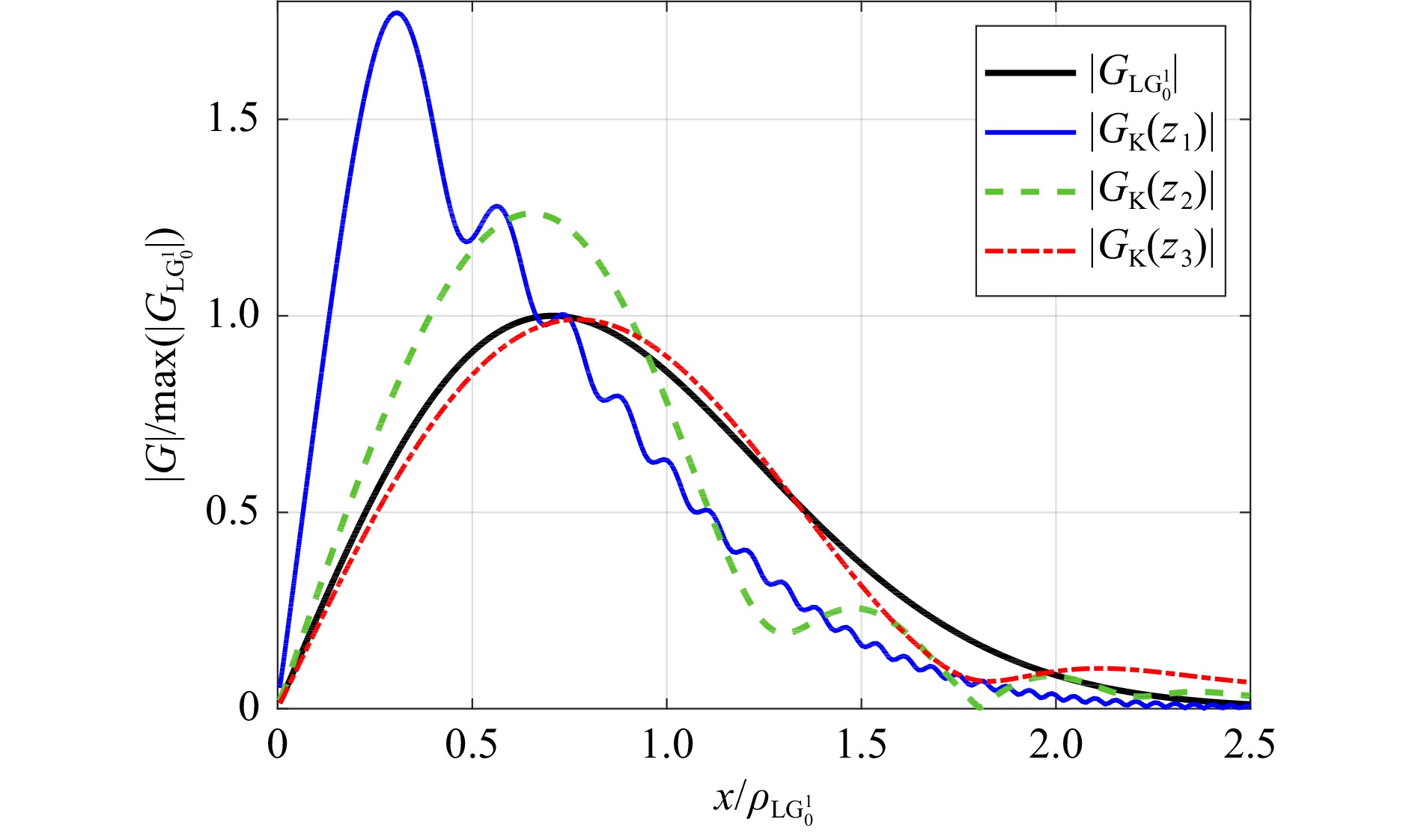
Fig. 4 Cross-section distribution of the Kummer beam amplitude modulus
$ |G_K| $ normalised to the$ G_{{\rm{LG}}_0^1} $ mode at the distances$ z_1=210 $ ,$ z_2=350 $ , and$ z_3=1000 $ mm for$ \nu_0 = 0.7 $ THz.The main reasons to consider Kummer beams are their distinct divergence and non-trivial field distribution. Since the ability to conserve energy flow plays an important role in information transmission, further we draw attention to the advisability of taking into account the features of diffraction propagation and analysing the evolution of the field structure. Also, we will study the effect of the finite number of sectors in the q-plate that usually was disregarded, although it significantly affects the entire beam configuration.
-
It should be noted that the results presented up to this point illustrate the features of the formation of a vortex beam in accordance with only the first three factors indicated earlier. Indeed, the frequency-resolved characteristics in Fig. 3 clearly show the influence of the achromaticity range of the elements (factor (i)), violation of the concentric structure in the spatial amplitude distribution within the spectral interval where the transmission of orthogonal transverse components of the vector THz field is inhomogeneous (e.g. on frequency
$ \nu = 2.7 $ THz, factor (ii)). The diffraction impact of a singularity introduced into the beam (factor iii), which leads to the formation of an amplitude distribution well approximated by the Kummer functions, was also seen in the frequency range 0.4 − 1.4 THz, and analysed in details in Fig. 4. Let us now turn to the influence of the factor (iv). In the case of the gradient q-plate, as shown earlier, the vortex beam has only concentric perturbations in the amplitude distribution (Fig. 5a). However, when the q-plate is composed of sectors, additional field disturbances inevitably occur from phase jumps at their radial junctions. In that case, the formed vortex beams have the 8-fold rotational symmetric field structure with specific lobes from each of the sectors (Fig. 5b).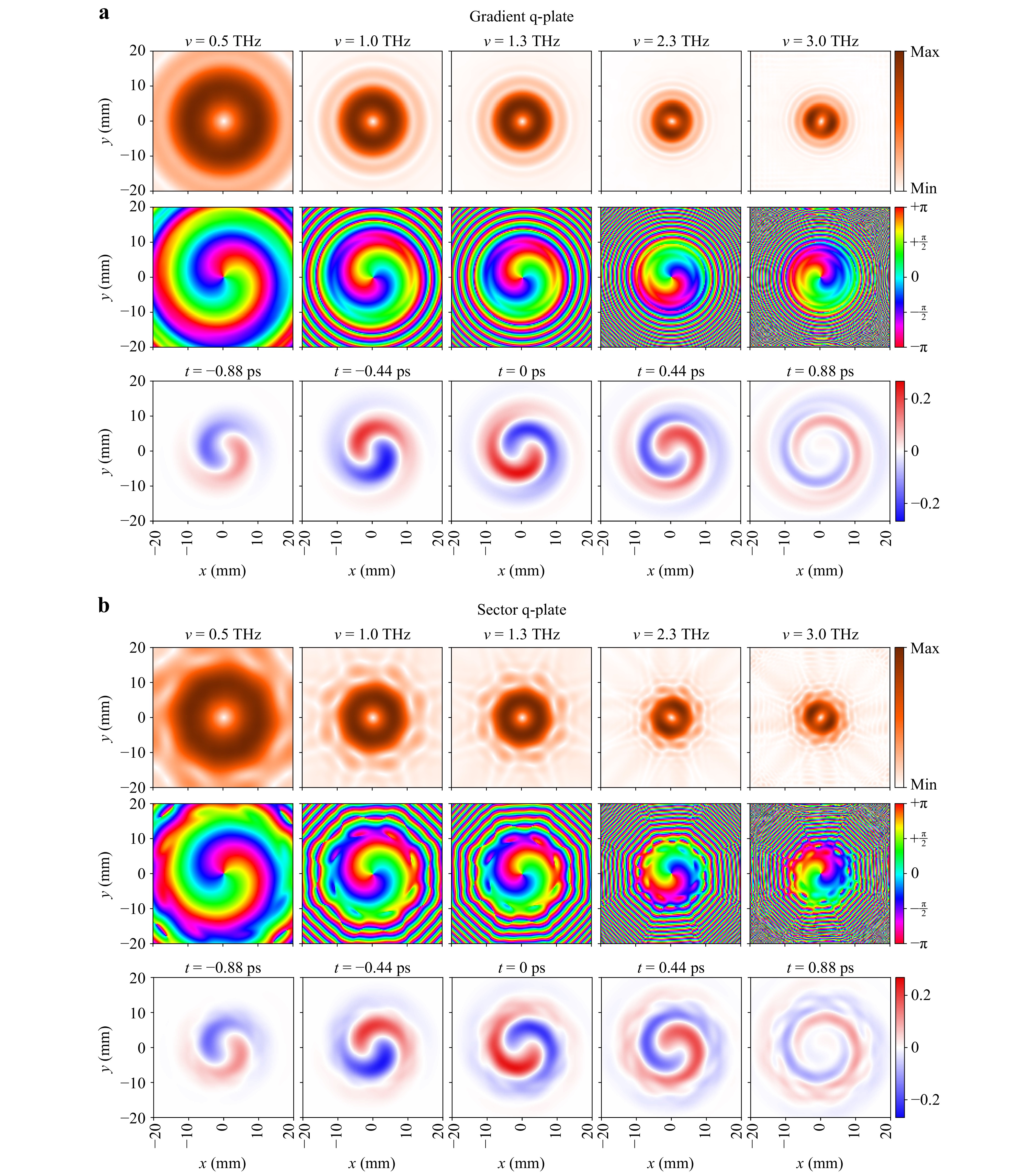
Fig. 5 Transverse spatial structure of the output diffracted field in spectral (upper two rows in a and b) and temporal (lower row in a and b) resolutions. Simulated vortex beam characteristics according to the two mathematical models: the gradient q-plate a and the sector q-plate b. Frequency (in THz) and time (in ps) are shown on top of the images.
The increased energy density in the Kummer beams for the near diffraction zone is promising for the tasks of wireless data transmission at short distances, as it allows to gain the level of the transmitted signal. Fig. 6 shows the evolution of the spatial-temporal distribution (first row) and the cross-sectional amplitude and phase distributions for the central frequency (second and third row, respectively). It is conditionally possible to distinguish three characteristic forms in the structure of the beam, as its diffraction evolution proceeds. The first form exists in the vicinity of the q-plate and is presented at the distance
$ z=210 $ mm, Fig. 6, when the observation plane is$ 15 $ mm away from the q-plate. In the near diffraction zone, the amplitude distribution is modulated by small speckles that have some characteristic radial direction. The phase distribution reveals an eight-sector structure. As the beam propagates further ($ z=250 $ and$ 300 $ mm in Fig. 6), it is possible to observe the THz field transformation into the second form, where the smoothing of the granular field structure begins: (i) speckles become larger and rotate according to the azimuth, in the direction of the energy circulation vector; (ii) simultaneously, an octagonal low-intensity zone is formed around the central beam point; (iii) the phase distribution reveals the births of a large number of singular point dipoles (pairs of helical phase dislocations with opposite topological charges)49,50. Finally, the speckled beam structure disappears, and the amplitude-phase distribution of the field becomes smoother. At$ z=600 $ mm it can be seen that the central vortex remains surrounded by only eight singular point dipoles. In the far zone (here$ z= 1000 $ mm), the singularity dipoles annihilate each other and the low-intensity octagonal contour becomes blurred and ceases to be visible in the background of the whole beam.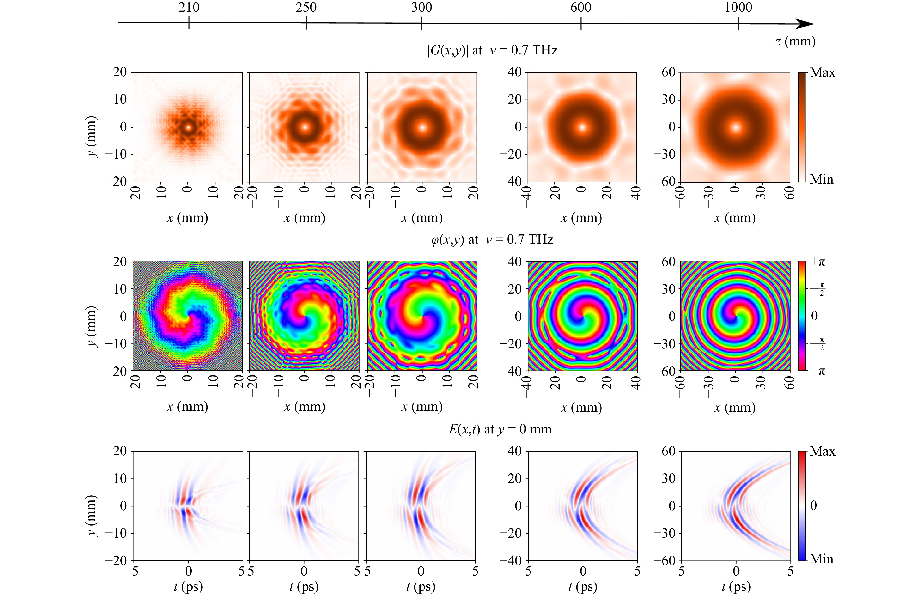
Fig. 6 Evolution of the structure of the Kummer’s BUTCH-beam field formed by the developed modulator.
The described free space diffraction processes correlate well with the Kummer beam diffraction nature (Fig. 4). However, an interesting feature is imposed by a discrete structure of the q-plate: a large number of vortex dipoles are formed, which in the process of beam propagation annihilate each other, and finally only one central vortex remains.
We can also see that the vortex THz field formed by the beam shaper with 8-sectorial q-plate transforms significantly during propagation. However, near the axis, it retains quite a regular structure.
-
In the second paper from this paired set, we have demonstrated the possibilities of theoretical analysis of the ultrabroadband THz wavefront behaviour as it passing through the partially-achromatic elements of beam converters. Based on the example of using multilayer quartz wave plates as key functional elements, we have shown how to relate the earlier developed mathematical model of THz PTDH, responsible for the simulation of wavefront propagation between polarisation elements with the Jones matrix formalism, describing the specific mechanism of polarisation transformation carried out by each layer of such wave plates. Thus, it becomes possible to study the integral transformation of the characteristics of the THz field during its interaction with all components of the modulator, as well as its further evolution during propagation in free space. It should also not be forgotten that the THz PTDH allows us to solve the additional problem of validation of beam characteristics after physical manufacturing of the designed modulator. It can be achieved through the experimental measurements of THz field in diffraction zone with its optionally subsequent numerical time-reversal to the modulator output plane, and even further backward propagation through the modulator components. Consequently, the proposed holographic approach allows carrying out numerical and physical experiments aimed at refining the design of the beam shapers in order to ensure the maximally possible matching between the characteristics of formed and desired beams.
To clearly illustrate the indicated possibilities, in this paper we have provided several examples of visualisation of the structure of scalar and vector beams formed by modulators based on a certain combination of quarter-wave and q-plate combinations with achromatic properties in the range of 0.4 – 1.4 THz. In particular, the features of the stage-by-stage process of formation of the vortex structure were revealed. It was also established that for a certain anisotropic phase delay formed by the wave plates outside the designed achromatic spectral interval, in a certain limited range of the high-frequency THz spectrum, it is possible to form a vortex structure with a topological charge sign opposite to the charge sign of vortex spectral components, which are formed within the working range of polarising elements. This difference in the sign of the topological charge revealed in the numerical study may not seem significant. Indeed, taking into account that the operating range of the achromaticity of these elements corresponds to the spectral interval of the maximum efficiency of the hypothesised THz radiation source, the opposite charged spectral components will have very low intensity, less than the noise level, and will be indistinguishable in a real experiment. However, it should be taken into account that there are possibilities for controlling the spectral characteristics of the elements making up the modulator, including the fact that reducing or shifting the operating range towards lower frequencies is allowable. Thus, the integral working characteristic of the modulator can also be modified to cover the spectral region where the formation of a charge of the opposite sign at moderate power will take place. That means, this observation and the use of the approach proposed in this paper open up great opportunities for the engineering of a new class of broadband beam shapers with a precisely controlled vector and vortex THz field structure within the operating interval.
The relationship between the characteristics of the achromatic components of the modulator and the formed vortex beams has also been discussed and demonstrated, such as the impact of the ellipticity induced by the quarter-wave plates on the azimuthal homogeneity of the amplitude distribution. The influence of axial singular point introduction into the beam by q-plate, which leads to the mode formation describing by the hypergeometric Kummer function together with the influence of the sector q-plate structure that triggers the appearance of radial jumps on phase distributions and reveals births of a large number of singular point dipoles in the middle diffraction zone have also been shown.
The spectrally and temporally resolved visualisation of the distributions of shaped THz field during its further free-space propagation have also been carried out.
We believe that the proposed approach will find applications in the design and advanced manufacturing of achromatic wave plates and beam modulators with custom characteristics.
-
Russian Science Foundation, Project No 19-72-10147. The work of A.G. is supported by EPSRC Grant No. EP/S018395/1
Design of broadband terahertz vector and vortex beams: II. Holographic assessment
-
Nikolay V. Petrov1, *, ,
 ,
, - Bogdan Sokolenko2,
- Maksim S. Kulya1,
- Andrei Gorodetsky3,
- Aleksey V. Chernykh1
- Light: Advanced Manufacturing 3, Article number: 44 (2022)
- Received: 18 September 2021
- Revised: 13 July 2022
- Accepted: 13 July 2022 Published online: 02 August 2022
doi: https://doi.org/10.37188/lam.2022.044
Abstract: In this paper, we demonstrate the capabilities of the terahertz pulse time-domain holography in visualisation, simulation, and assessment of broadband THz vortex beam formation dynamics upon its shaping by elements of beam converter, and further propagation and manipulation. By adding Jones matrix formalism to describe broadband optical elements, we highlight the differences in the spatio-spectral and spatio-temporal structure of the formed vortex and vector beams dependence on the modulator used and visualise their modal features. The influence of diffraction field structure from each element in the broadband vortex modulator is revealed in numerical simulation and the formed beams are analysed against the simplified Laguerre-Gaussian beam model.
Research Summary
Design of broadband terahertz vector and vortex beams: II. Holographic assessment
The formation of broadband terahertz vortex and vector beams attracts increasing attention due to the prospects for using such beams in telecommunications, imaging, and sensing of material properties. One of the most effective ways for THz beam shaping is geometric phase approach based on a spin-orbit conversion principle. Nikolay V. Petrov from ITMO University and colleagues solved a problem of assessment of broadband terahertz beams properties by application of terahertz pulse time-domain holography for tuning the beam shaping components to ensure maximally possible matching between the characteristics of formed and desired beam. The technique allows estimating the spatio-temporal and spectral characteristics of the THz field inside the modulator and at its output. As examples of beam shaping devices, combinations of multilayer achromatic quartz wave plates as the main functional elements were considered and analyzed.


Rights and permissions
Open Access This article is licensed under a Creative Commons Attribution 4.0 International License, which permits use, sharing, adaptation, distribution and reproduction in any medium or format, as long as you give appropriate credit to the original author(s) and the source, provide a link to the Creative Commons license, and indicate if changes were made. The images or other third party material in this article are included in the article′s Creative Commons license, unless indicated otherwise in a credit line to the material. If material is not included in the article′s Creative Commons license and your intended use is not permitted by statutory regulation or exceeds the permitted use, you will need to obtain permission directly from the copyright holder. To view a copy of this license, visit http://creativecommons.org/licenses/by/4.0/.

 DownLoad: