


HTML
-
Optical micro and nanofibres (MNFs) have extensive applications in nonlinearity generation1-5, near-field optics6-9, quantum optics10-13, and miniaturized sensing14-19. Although MNFs have fostered the development of various disciplines, their own study was barely considered until the convenient fabrication of low-loss MNFs was made possible. In 2003, Tong and Mazur proposed a two-step process in which MNFs could be drawn directly from silica nanowires, preserving the integrity of high light transmission by virtue of excellent surface smoothness and diameter uniformity20. In the study of these authors, as well as in similar studies available in the literature, the fibre material would be first softened by local heating and then thinned and elongated by applying a pulling force21,22. The decreased diameter of fabricated MNFs can approach the subwavelength dimension, thus supporting modal fields with strong evanescent waves tunnelling through the silica material into the surrounding medium23. Easy fabrication, low loss, light mass, and pronounced evanescent waves have made MNFs one of the best candidates for the study of light-matter interactions through evanescent fields.
Many efforts have been devoted to improving the fabrication units to produce MNFs of desired quality. The most common taper-drawing machine contains a flame and two translation stages that apply the pulling force to the fibre by stretching its fixed ends in opposite directions23-25. According to the hot-zone theory presented by Birks, the specific shape of MNFs is determined by the length variation of the heated region relative to the net elongation of the fibre26. Practically, MNFs with designed taper geometries can be prepared by adopting the “flame brush” technique to manipulate the hot zone27,28. However, the use of flames to heat the fibre suffers from air fluctuations and inertia of the moving burner. Electrical heaters were then introduced for programmable and steady temperature distribution29,30. Alternatively,
$ CO_2 $ lasers can serve as turbulence-free heat sources that generate heat through material absorption, the function of which, however, requires complex optical alignment and high input light power (~a few watts)31-33. The substitution of translation stages, on the other hand, can take multiple forms provided that the pulling force can be exerted along the fibre34-36. Although the aforementioned techniques in principle provide a myriad of viable fabrication configurations, each specified for certain operational conditions, they are explored only within the most explicit scheme of “heat and pull”.In this study, we demonstrate a unique technique for MNF fabrication that, counterintuitively, excluded the use of any of the aforementioned bulky fabrication components. In short, pieces of metal plates were introduced to serve as portable microsized heaters, which absorbed fibre-delivered light efficiently through plasmonic effects. Thus, the light power required in this step was only a few microwatts. The pulling force was handily provided by the tensile stress of the macroscopically bent fibres without use of translation stages. We emphasise that the proposed plate-fibre system was self-sufficient in terms of both heat and pull, the implementation of which thus required no conventional bulky accessories, such as the translation stage, flame burner, or free-space optical components (which are typically required for the
$ CO_2 $ laser-involved fibre taper fabrication). Owing to its small volume, the plate–fibre system could be transferred into a scanning electron microscope (SEM) chamber, where the dynamic tapering process was visualised with nanometre precision for the first time. -
Schematic of the experimental set-up is shown in Fig. 1a. A pre-tapered microfibre (fabricated using a flame-heated drawing machine) is mounted on a glass slide using conductive tapes (to alleviate the charging effect) with a gold plate attached to its side face. The fibre-plate system is placed inside the SEM chamber, connecting external light sources via an optical-through-vacuum connector. An all-fibre optical path is adopted to simplify the alignment of different optical components across the chamber while maintaining a high light-transmission efficiency. During the fibre tapering process, the morphological evolution of the system is directly visualised and monitored in-situ at nanoscale.
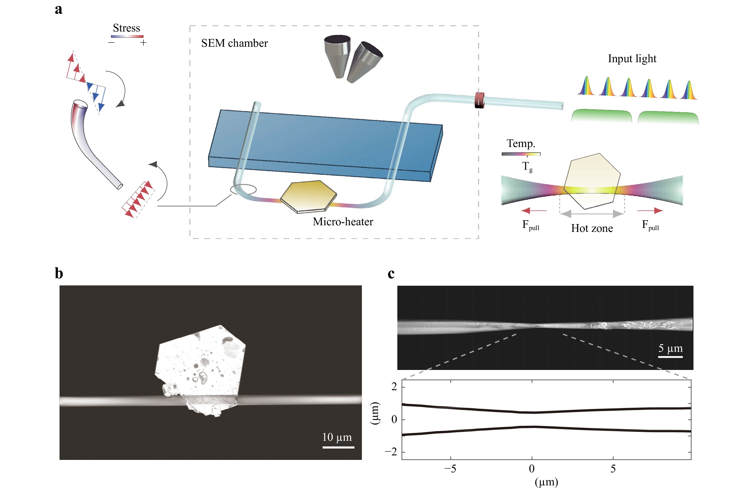
Fig. 1 Tapering a fibre inside an SEM chamber using a plasmonic heater and the deformation-induced pull. a Schematic of the experimental set-up, showing a pre-tapered fibre with a metal plate attached to it inside the SEM chamber. The modulated light is guided into the fibre via an optical-through-vacuum connector. The light-thermal effects are monitored in real time with nanometre precision. The insets sketch the stress distribution and temperature profile of the fibre in selected regions; the positive normal stress denotes tensile stress and
$ Tg $ represents the glass transition temperature. b SEM image of a gold plate (long side length: 20$ \mu $ m; short side length: 10$ \mu $ m; thickness: 45 nm) attached on a pre-tapered fibre (waist diameter: 3.3$ \mu $ m). c SEM image and measured profile of the as-fabricated fibre (central diameter: 850 nm) drawn from b The measured average light power was 8.2 mW.In the experiments, the pre-tapered fibre, directly drawn from a standard fibre, was controlled to have a diameter ranging from one to six micrometres, thereby guaranteeing relatively strong evanescent fields and robust mechanical strength (Fig. 1b). To provide the pulling force along its axial direction, the pre-tapered fibre was intentionally bent to a door-shaped structure and fixed onto a glass slide, as indicated in Fig. 1a (see also Fig. S1D). Mechanical analysis revealed that tensile stress was naturally induced in the fibre (details are provided in the next section). As the temperature increases during heating, a drop in the viscosity of the fibre material, together with the deformation-induced stress, would cause the fibre to stretch itself and be drawn thin. In particular, we noticed that the elastic bend would always locate in the transition region of the pre-tapered fibre, which features self-modulation properties with regard to the drawing force, thus preventing abrupt breakage of the fibre36.
The heat required to soften the fibre was generated by plasmonic absorption of microsized gold plates, the thickness and transverse dimension of which were in the range of several tens of nanometres and micrometres, respectively. By delivering light into the microfibre, a fraction of electromagnetic energy would evanescently leak out into the surrounding medium, exciting surface plasmon polaritons (SPPs) supported by the attached gold plate. The optical absorption in the plates was accordingly enhanced (see the calculated absorption spectra in Fig. S3A), which in turn caused the temperature of the fibre to increase through heat transfer. Experimentally, we used a supercontinuum light source (wavelength: 400 nm - 2400 nm; pulse width: 4 ns) and a modulated continuous-wave (CW) light source (wavelength: 532 nm) to achieve different patterns of heat deposition. The operating power of both sources required to soften the fibre was at milliwatt level. To control the amount of heat accumulation, the light power, and additionally the repetition rate for the supercontinuum light can be tuned.
Fig. 1b, c show SEM images of the plate-fibre system before and after the proposed fibre tapering using the supercontinuum light source (the dynamic process can be visualised in Movies S1–S2). The initial pre-tapered fibre had a diameter of 3.3
$ \mu $ m. After tapering, the thinnest part of the fibre reached the submicrometre scale (850 nm in Fig. 1c). To reveal the specific configuration of the taper, we removed the molten material with sonication and measured its profile, which is shown in the lower panel of Fig. 1c (see Figs. S2A, B for further details). No apparent taper waist can be observed; it is submerged in the neighbouring transition regions. In addition, the diameter of the fabricated fibre varied by more than 70% within a few tens of micrometres, suggesting ultra-short transition regions and a nonadiabatic geometrical evolution along the axial direction. Assuming the hot-zone theory still holds26, the tiny size of the microheater, compared to that of conventional heaters, is the key to produce such nonadiabaticity and transition regions at a length scale of the same order. Given that only the fibre near the microheater can be effectively heated and softened, the resultant elongation is small, as is the length of the transition region. Another notable feature of the fibre taper is its asymmetry, which is not accidental. Instead, this asymmetry was observed in multiple other fibre samples (Fig. S2). We attribute this phenomenon to the asymmetry of stress in the manually deformed fibres. Further explanation is provided in the next section.During the experiments, while keeping the single pulse energy at a constant level (< 1
$ \mu $ J), when the repetition rate of the supercontinuum light was set below 10 kHz, we observed the spiral motion of the gold plate around the fibre (Movie S3). This motion was the result of surface elastic waves, a phenomenon reported in a previous study of ours37. However, as the repetition rate increased to 100 kHz, the accumulated heat could no longer be completely diffused within the narrow cooling window. As a result, ablation of the gold plate would occur (Fig. 2a). First, the gold plate would appear tattered, exhibiting the characteristics of solid-state dewetting of thin films38. Later, the entire structure would collapse with the continuous injection of heat (Movie S1). Laser ablation of the plate would enhance its contact adhesion to the fibre (the gold plate would stick to the fibre in a partially molten state), thereby creating an unsurmountable friction force for elastic-wave-driven locomotion. Another plausible interpretation is that, at high repetition rates, the intensified heat accumulation would bring the temperature evolution of the plate close to that obtained using CW light, thus mitigating the excitation of elastic waves. Therefore, the gold plate would remain stationary and function as a static microheater. Given that the ablation threshold of gold microplates is below the glass transition temperature ($ Tg \approx $ 1473 K) of fused silica, the attached gold plates would experience multiple stages of light ablation prior to the starting point of fibre tapering when the viscosity of the fibre was sufficiently low to be stretched thin under the implanted tensile force36,39. Similarly, in the case of the CW laser source, the fibre would get softened after the gold plate was ablated, which was accompanied by observable thermal expansion (Fig. S4 and Movie S4). This sequence of events suggests that, although ablated, the gold plates still possess the capability to generate plasmonic heat that is not compromised.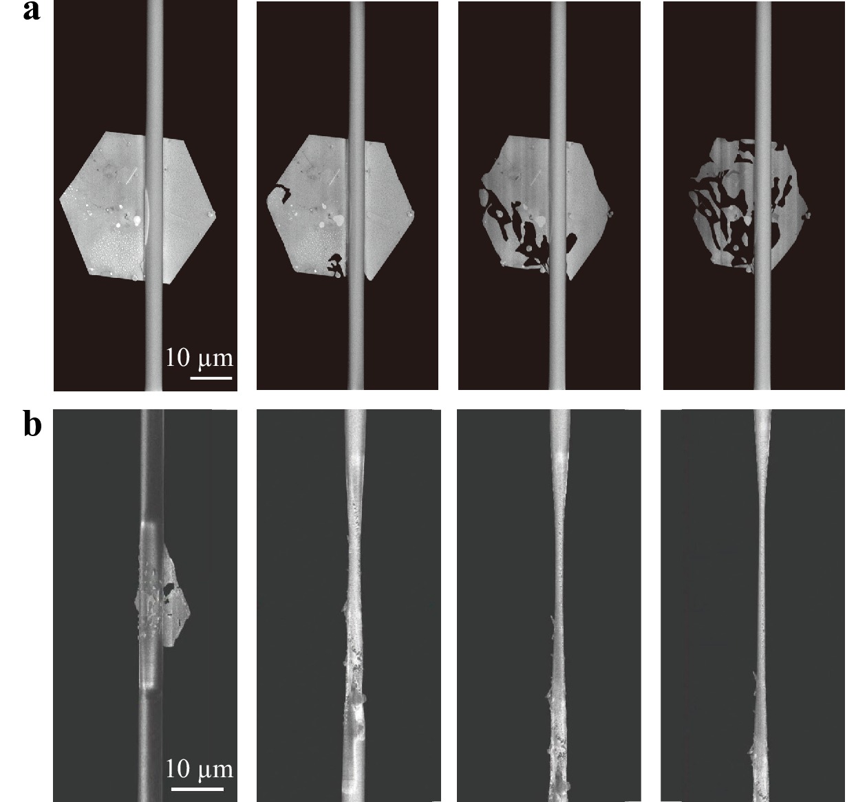
Fig. 2 In-situ monitoring of different stages of the fibre tapering process. a SEM pictures showing that the attached gold plate was first ablated before the fibre was tapered. The degree of laser ablation increased over time from left to right (0 s, 20 s, 30 s, and 44 s), while the underlying silica fibre remained intact. The measured average light power was 7 mW. b Fibre tapering process suspended by light source intervention. After the heat accumulation was sufficient to soften the fibre, the progress of the fibre tapering process was controlled by manually switching the light source between the on and off states. From left to right, the diameters of the thinnest part of the fibre are 4.57
$ \mu $ m, 2.42$ \mu $ m, 1.51$ \mu $ m, and 1.12$ \mu $ m, respectively. The measured average light power was 7.6 mW. The dynamic process was recorded in Movie S5.The fibre tapering process can be divided into different stages by manually switching the light source off and on. Movie S5 shows an example in this regard, and SEM images of the fibre taper in the corresponding stages are displayed in Fig. 2b. Typically, the first stage, that is, the fibre-tapering process before the first intervention of the light source, would be the most drastic and abrupt, given that it involved the phase transition of the fibre from the glassy state to the viscous state. Nevertheless, the first elementary pulling would be restrained by the length of the hot zone (a few tens of micrometres). The dynamics of the rest of the tapering process was gradual and moderate and could be readily controlled to freeze or continue via light source intervention. The recorded movie reveals that after the fibre drawing process was initiated (which means that a sufficient amount of heat had already been deposited into the system), switching off the external light source functioned as removing the heat source, which froze the dynamic tapering process to the corresponding state at the moment. Since the plate–fibre system was placed in a high-vacuum environment, heat loss through convection was blocked, and the temperature of the fibre would not quickly drop well below
$ Tg $ . Therefore, the tapering process that was previously suspended would follow immediately after the light source was restarted. Given that the diameter reduction of the fibre taper within neighbouring interventions occurs at submicrometre level, this process can only be clearly observed in-situ inside an SEM. In ambient environments, despite the fact that the same “heat and pull” mechanism still holds (with higher input power owing to air convection), the concrete morphological evolution and underlying physics will be difficult to track.In this study, we mainly focused on gold plates as the portable microheater, the choice of which is nevertheless not exclusive. We tried mechanically exfoliated topological insulators (
$ Sb_{2}Te_{3} $ ) and amorphous metallic plates, both of which proved to be efficient microheaters (Fig. S2). Indeed, all light-absorptive materials capable of converting electromagnetic energy to heat can be used as heat sources in the proposed experimental configuration; while plasmonic materials require much lower input light power. -
The proposed technique exploits the microscale light-thermal effect and macroscopic deformation-induced pulling force to taper down a fibre, which establishes a new method for MNF fabrication. To gain insight about the mechanism underlying the tapering process, next we trace back to the origins of “heat and pull” from a theoretical viewpoint.
Heat.– First, we calculated the light absorption of the plate–fibre system (the simulation model replicated the experimental geometry shown in Fig. 1b). The absorption spectrum displayed in Fig. S3A indicates the efficiency of heat generation inside the plate–fibre system in response to the supercontinuum light source used in the experiment. The gold plate and fibre in contact jointly function as a hybrid metal-dielectric waveguide. Given that the excitation of SPPs requires light fields carrying the electric component perpendicular to the metal-dielectric interface, the gold plate selectively absorbs more evanescent waves when the light field is guided in
$ HE_{11}^{vertical} $ mode (see the modal profile in the inset of Fig. S3A)40-42. The total heat conversion efficiency depends on both the propagation loss of the hybrid waveguide and coupling efficiency between the fibre mode and SPP mode; it was calculated to be approximately between 2% (off-resonance) and 10% (on-resonance) for the$ HE_{11}^{vertical} $ mode. The total heat generation efficiency in both situations (on- and off-resonance) did not differ significantly owing to the finite fibre-plate contact length and propagation attenuation (the comparison is shown in Fig. S3D, E).Fig. 3a displays the absorbed power profile inside the gold plate at the resonant wavelength (
$ HE_{11}^{vertical} $ mode, 775 nm). As is one of the main characteristics of SPPs, the electromagnetic fields feature subwavelength-scale localisation around the contact line between the plate and fibre, with the light intensity quickly attenuating along the width and thickness directions, which suggests the significance of the contact length relative to other geometric parameters. As a result of the guide-mode interference, the specific E-field distribution would change as a function of the wavelength and geometric configuration (Fig. S3D-G). Those effects, however, would be smeared out by the heat transfer through the plate into the fibre.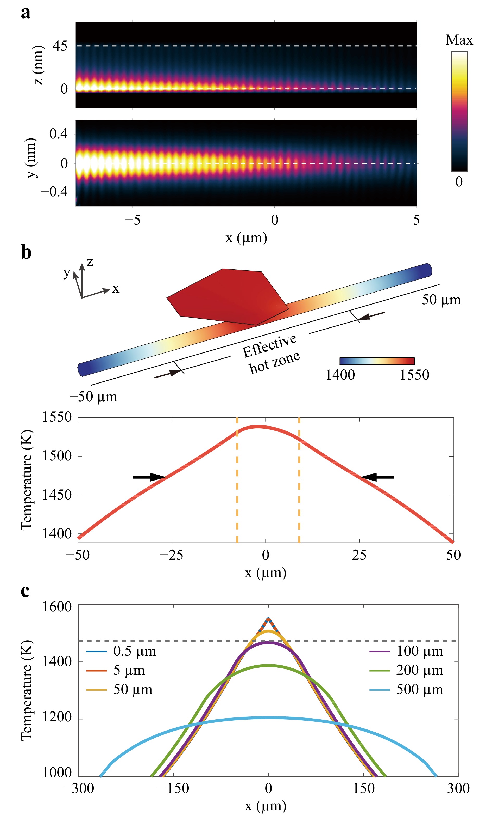
Fig. 3 Simulation of heat generation from light absorption. a Absorbed optical power profile of a gold plate (Fig. 1b) at maximum absorption wavelength (
$ HE_{11}^{vertical} $ mode, 775 nm) in the x-z plane and on the lower surface in the x-y plane. White dashed lines (top panel) indicate the thickness span of the gold plate. b Temperature distribution of the plate-fibre system calculated in a steady-state regime. The subplot at the bottom shows a characteristic temperature distribution along the fibre-plate touching line (arrows and dotted lines mark the glass transition temperature of fused silica and transverse boundary of the gold plate, respectively) c Influence of the heat source dimension on the temperature profile of the fibre along the axial direction. Temperature curves corresponding to heat source dimension below 500 nm are highly overlapped; they are not shown for the sake of clarity in the graphical representation. The gray dashed line denotes the temperature threshold.Next, to elucidate the thermal response of the plate-fibre system to light absorption, heat transfer simulations were first performed in the static regime for the following reasons. The gold plate, referred to as the microsized heater in the context, generates heat via plasmonic effects and pumps it into the system, causing a considerable temperature rise. To thermally initiate the tapering process, groups of pulses should collectively and constructively contribute to accumulate heat, for which the very prerequisite is to set a high repetition rate of the light source (~100 kHz in our case). Once heat accumulation is assured, at an early stage, pulse-wise temperature rise is expected, as will be discussed later. However, the system will finally evolve into a thermally semi-stable state, where the system temperature is essentially invariant, with only slight periodic perturbations caused by the input light pulses and subsequent cooling. The latter stage can be approximated by static-state simulations, especially given that in the experiments, the time scale of the mechanical tapering process was measured in seconds, which is adequate for the balance to be reached in the fibre-plate system between the nanopulsed heat influx and outflux (see Fig. S4D for comparison. The response time with a 1-Hz modulated CW light source is within one second).
To examine the final profile of heat accumulation, we considered that a continuous 8-mW input power was injected into the system (the same simulation model used for electromagnetic calculation, based on Fig. 1b), corresponding to the average power of the pulsed light source. With the spatial distribution of the heat source inherited from that in Fig. 3a, the calculated temperature profile is displayed in Fig. 3b. Owing to the averaging effect of heat transfer over time, the resultant temperature profile is not traceable to the original E-field distribution, as shown in Fig. 3a. Instead, it is determined by the dynamic balance between heat influx and outflux, as demonstrated above. For simplicity and qualitative analysis, we chose to disregard the relaxation behaviour of the glass transition process. For the same reason, the phase change or laser ablation was not included in the heat transfer model. Specifically, a definite threshold temperature was set at 1473 K, beyond which the fibre could be sufficiently softened to be stretched and elongated. Bounded by this threshold condition
$ T>Tg $ (indicated by arrows), the length of the effective heat zone surpasses the spatial range of the contact line (indicated by the gold dashed line) while still maintaining a relatively small dimension of a few tens of micrometres, which is consistent with the taper length obtained in the experiments.The reduced size of the microheater played a major role in narrowing down the heat zone. To illustrate this size effect, we considered a fixed rate of heat deposition (adopting the same absorbed optical power as in Fig. 3b, which is a practical value considering both the allowable light power used in the experiments and the simulated heat conversion efficiency) assigned to heat sources with various dimensions. Given that the major concern here was the dimension of the heat source, for the purpose of variable control, the heat source was assumed to be uniform, regardless of the E-field distribution. Fig. 3c shows the resultant temperature profile along the fibre axis. Note that the dependence of the temperature uniformity on the heat-source dimension is plainly revealed. As the heat source dimension decreases below 5
$ \mu $ m, the corresponding temperature profile of the fibre converges, approaching that of a point source. In the experiments, although the size of the microheaters was in the range of a few tens of micrometres, the exact contact length could be properly adjusted to a few micrometres, as is the case exhibited in Fig. 1b. Therefore, it is inferred that the microheaters can generate a point-source-like hot zone in which the temperature gradient is significant. The nonuniform temperature profile in the hot zone further renders a similar gradient distribution of the viscosity of the softened fibre, thus causing inhomogeneous stretching of the fibre (that is, a less viscous, hotter region would be stretched faster than a more viscous, colder region). This explains why the resultant fibre taper showed a nonuniform waist (Fig. 1c). In comparison, when the heat source dimension is in the submillimetre regime, the corresponding temperature profiles tend to flatten, which is associated with a drop in the peak temperature as a compensation for a larger heating area. This latter observation indirectly suggests that, although the heat conversion efficiency generally becomes lower when the size of the plasmonic heater decreases, its salient peak temperature nevertheless reduces the burden of the input light power required to soften the fibre. Furthermore, given that the basis of the hot-zone theory is the assumption of an equally heated hot region, it only applies in cases where the heat source is above the millimetre scale, e.g., the flame burner26. For a highly localised heat source, modifications are needed to account for the temperature nonuniformity, and waist-less tapers are to be expected.To verify the aforementioned insight obtained from simulation, that is, the fact that the microheater could generate sufficient heat to soften the fibre material, we transferred gold plates to standalone straight fibre probes (to exclude the impact of macrobending) and coupled light into them. Both the pulsed light source and CW laser were used in the experiment. The average input power of both sources was a few milliwatts. With light leaking out from the thinned region near the probe tips, the gold plates began to heat the fibres till the point at which the silica material visibly shrunk and exhibited liquid-like behaviour (Fig. 4 and Movie S8), suggesting effective heating and softening of the fibre induced by light-thermal effects. Further increasing the light power led to the formation of microbumps on the tips of the probes, similar to the reported phenomena in which
$ CO_2 $ lasers with a few watts of input power were used to generate microcavities in silica fibres43. For fibre material away from the heated region, the solid-state geometry was still well preserved.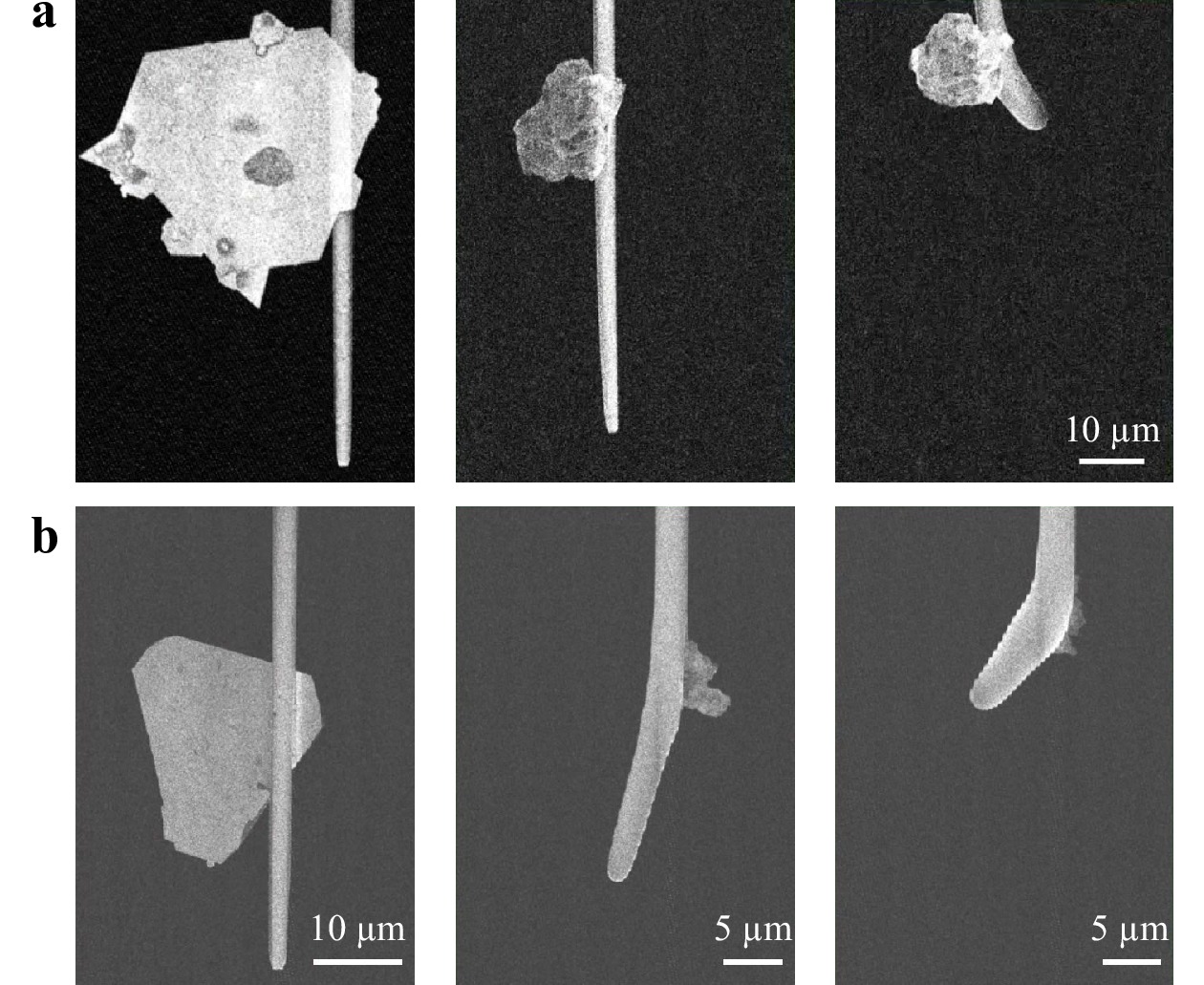
Fig. 4 Softening fibres through plasmonic heating effect. Sequential SEM images showing the softening of fibre probes by the modulated (1 Hz) CW light at 532 nm (a) and supercontinuum light with 100-kHz repetition rate (b). The measured average light power was 15.2 mW in (a) and 10.1 mW in (b).
The early stage of the heat accumulation scheme was also considered, during which the heating effects of individual pulses are not yet overwhelmed by the accumulated temperature background. In nanosecond laser heating of microobjects, electrons were found to be in equilibrium with the lattice in previous studies44,45. Therefore, the classical heat transfer picture still holds, and the time-dependent Fourier heat conduction model was adopted in this study with slightly modified thermal properties for micro and nanoscale materials45. Gaussian pulses with 4-ns pulse width and an integrated pulse energy of 10 nJ were set up in the simulation based on the experimental measurements. Under single-pulse illumination, Fig. 5a illustrates the temperature evolution probed within the plasmonic hot region (far end of the plate–fibre contact line). Here, we can see that while the temperature almost synchronises with the light pulse at the rising edge, the cooling process evolves slowly and exhibits a long trailing end. Moreover, Fig. 5b shows the temperature evolution probed at positions away from the plasmonic hot region (probe locations are indicated in the inset of Fig. 5d), which is in stark comparison with Fig. 5a. The widened and time-delayed temporal envelopes suggest a retarded heating process of the fibre due to slow heat conduction (heat convection can be ignored in high vacuum and radiation contributes little in the low-temperature regime). The transient process of heat transfer can be further visualised in Fig. 5c, which shows the temperature distribution of the fibre-plate system in four snapshots taken from an extended period of 1 ms. At 10 ns, the temperature profile still resembles that of the absorption profile. As the heat transfer proceeds, the input energy is distributed more evenly across the fibre–plate system. Given that the thermal diffusivity of the gold plate and fused silica differ by two orders of magnitude (
$ \alpha_{Au} \sim 10^{-4}\; m^2 $ /$ s $ ,$ \alpha_{fibre} \sim 10^{-6} \;m^2 $ /$ s $ ), while the gold plate is quick in reaching temperature uniformity, the fibre appears more lagging in dissipating the incoming heat flux from the heat source.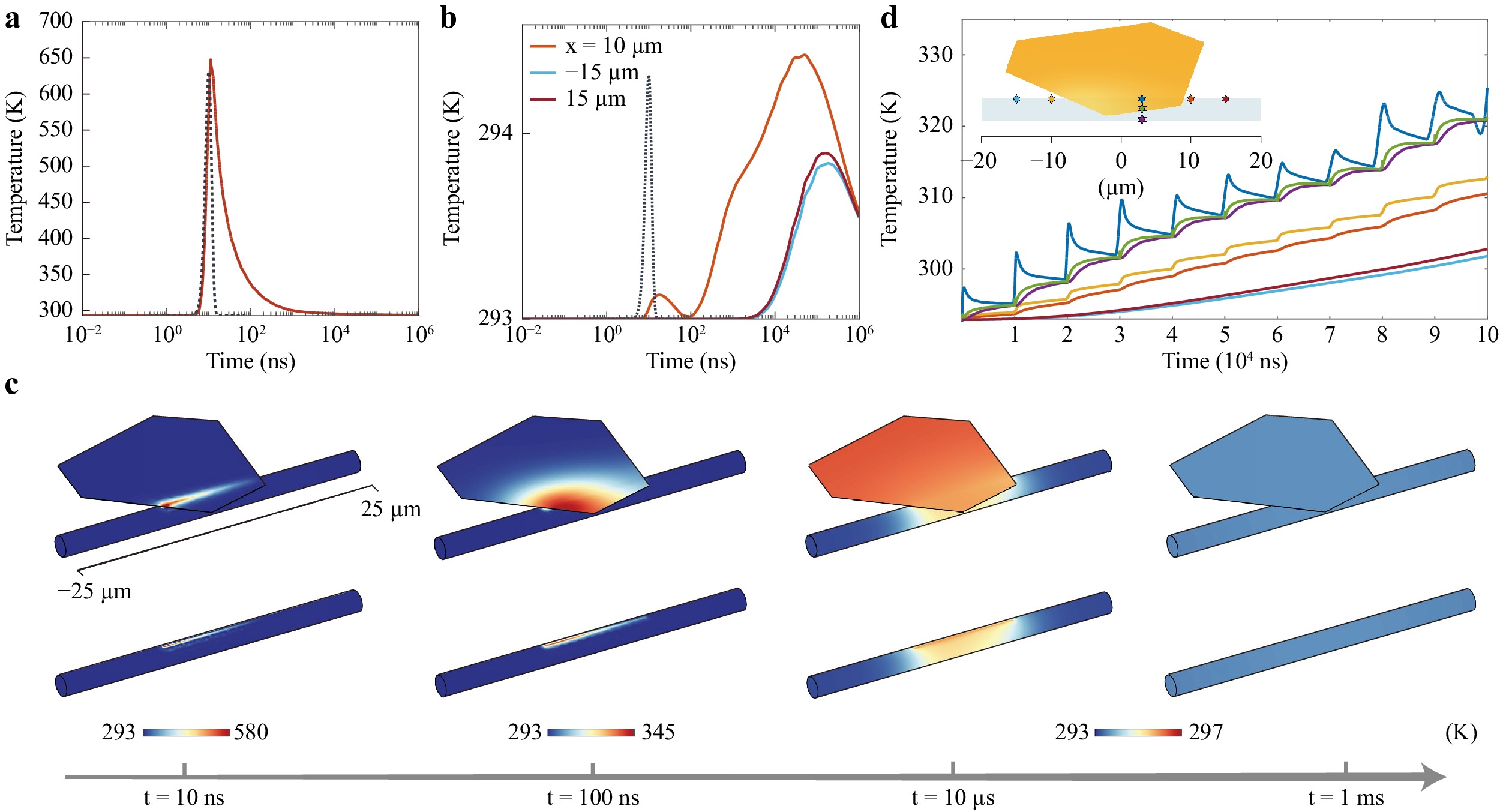
Fig. 5 Simulated transient temperature response to pulsed heat load. a Temperature evolution at a selected point inside the plasmonic hot region under the incidence of a single light pulse. The time evolution of the input Gaussian pulse (10-ns time delay) is plotted as a dotted curve for comparison. b Temperature evolution at three selected points on the outer surface of the fibre.
$ X $ coordinates of the three points are labelled in the legend, corresponding to the inset in d. In the orange curve, the minor temperature increase prior to the major one is caused by the heat flux coming from the right edge of the gold plate. The time interval between the two temperature envelopes corresponds to the time for the heat to travel across the plate. c Temperature profiles of the fibre-plate system as four snapshots taken from a time duration of 1 ms, featuring heat transfer at different stages under a single pulse illumination. d Heat accumulation scheme with consecutive incidence of ten pulses (repetition rate: 100 kHz). Sampling points were chosen to be aligned either vertically or horizontally on the fibre to display the heat transfer along both directions.The retarded heat transfer allows heat to accumulate in pulses, as shown in Fig. 5d. As the repetition rate of the light source increases, the long tail of the cooling edge of the current heat pulse gradually overlaps with the next incoming temperature rise. Therefore, the starting temperature of each pulse is based on the accumulated effect of previous pulses, guaranteeing that the system can be heated constantly46,47. Another remarkable aspect is the smearing effect of the pulse-wise temperature evolution. An external observer with millisecond temporal resolution (common for heat-driven dynamic processes) could hardly resolve the dynamic changes occurring within a few hundred nanoseconds. A smoothed temperature envelope would be detected instead, resembling that of steady-state heating, and the effect would be the same if the observer were located far from the pulsed thermal source48(see the two curves at the bottom right of Fig. 5d). The temporal response of the plate-fibre system to the modulated CW laser features a pattern of quasi-stationary heat transfer, the details of which are provided in Section S1 of the Supplementary Information.
Pull.– While heat takes effect within a localised region at microscale, the other element of the proposed fibre tapering, namely the pulling force, is implanted in the system at macroscale. Specifically, this force is determined by the equilibrium of the bending moment in the fibre deformed in a designed pattern. As sketched in Fig. S6A (see also Fig. S1D), the deformed fibre is composed of a transversely suspended region, two vertical holders, and two bending regions connecting the former two parts, which combine to form a "door-shaped" structure. The bending regions are associated with bending moments inversely proportional to the radius of curvature. The equilibrium condition requires that the suspended region, though barely bent, should possess a specific stress distribution to generate a counter-moment offsetting the one at the bending region (see the left panel in Fig. 1a). Consequently, the suspended region where the microheater is placed is bound to be subject to a pure pulling force; a detailed discussion on this point is provided below (see also Supplementary Section S3).
The door-shaped deformation pattern was quantified by extracting the radius of curvature of a symmetrically deformed fibre, as shown in Fig. S6B. Note that the smallest bending radius (largest bending curvature) is located within the two bending connectors, and it increases along the fibre axis towards the centre of the suspended region, where the fibre becomes nearly straight with a bending radius greater than 1 m. By scanning the view of the optical microscope along the deformed fibre axis, the part of the fibre with the smallest bending radius was found to be located within the transition region of the pre-tapered fibre, the scale of which was typically a few millimetres. Fig. 6a exhibits an optical image of this example. The average bending radius of the displayed region is 3 mm.
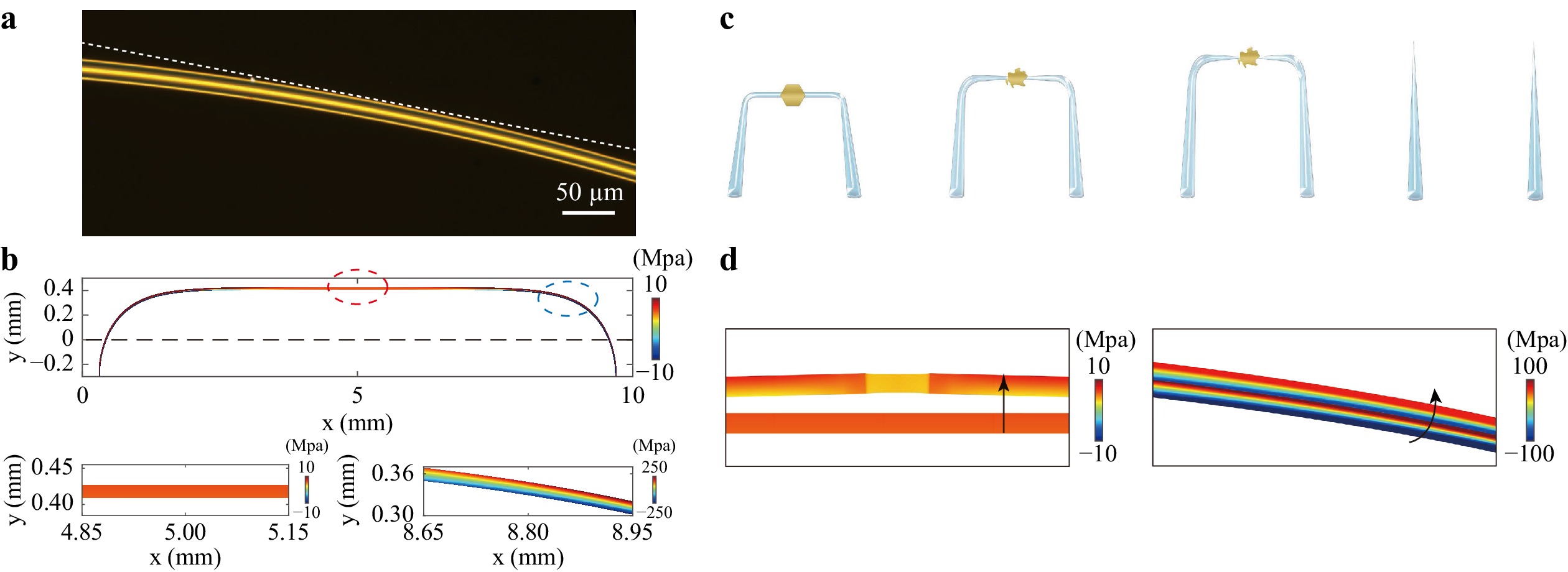
Fig. 6 Pulling force in a door-shaped fibre. a Optical microscopy image taken within the transition region of a pre-tapered fibre. The straight white dashed line is a reference to indicate the fibre bending (average radius of curvature equal to 3 mm). b Simulated distribution of the second Piola-Kirchhoff stress along the axial direction in a deformed fibre. The black dashed line denotes the initial position of the fibre (straight) before it is deformed into the door-shaped structure. Stress distributions of regions marked by red and blue circles (average radius of curvature equal to 3 mm) are subplotted at the bottom, showing the axial evolution of the normal stress due to evolution of the fibre geometry. c Schematic of the self-stretching process, featuring a forward motion of the suspended region and straightening of the bending connector after sufficient heat deposition (indicated by structural damage of the microheater due to laser ablation). The fibre would eventually rupture if the light input was not terminated on time. d Simulated results showing the shift of the fibre after sufficient heat input in a specified hot zone (length equal to 40
$ \mu $ m). The two subplots correspond to the suspended region (left) and bending connector (right) in b.To reproduce the manually applied deformation computationally, solid mechanics simulation was performed, in which inward rotations were prescribed for the two outermost regions of a cylindrical fibre (Movie S9). The stress distribution in the resultant door-shaped structure is shown in Fig. 6b. Owing to the large deformation in the simulation model, the geometric nonlinearity was taken into consideration by using the Green–Lagrange strain, and the second Piola-Kirchhoff stress along the deformed axial direction was selected as a quantifier for the normal stress.
Note that the bending and suspended areas (circled in blue and red, respectively, in Fig. 6b) behave differently: the normal stress inside the bending area has opposite signs on the convex and concave sides, suggesting a transition from tensile stress to compressive stress across the cross-section and the existence of a neutral layer in between. The stress distribution in the bending region is similar to that of a cantilever beam subjected to pure bending. In comparison, the suspended region only experiences tension, thereby echoing the moment analysis described above. We attribute this axial evolution of the normal stress to the geometrical evolution of the deformed fibre, particularly to the axial evolution of the bending curvature. In contrast, a circumferentially deformed fibre possesses a similar curvature through the bending connectors towards the suspended region, all of which feature the cantilever-like stress distribution (Fig. S6C, D). Indeed, the generation of pure tension can only be guaranteed by the law of moment equilibrium in the specified deformation manner, i.e., the door-shaped structure. For a pre-tapered fibre deformed in the door-shaped manner with an axially varying diameter, as in the experiment, the tensile stress within the suspended region can be several orders of magnitude larger than the maximum stress at the bending connectors owing to the reduced cross-section (Fig. S8). The calculated normal stress is below the rupture stress of tapered fibres measured experimentally49.
After the fibre is softened with heat input, the internal stress distributed in the deformed fibre can be released through a self-stretching process, as schematically illustrated in Fig. 6c. First, since the localised hot zone is always in the suspended region where the microheater is placed, the softened fibre material is subjected to pure tensile stress, and will be tapered and drawn thin, as predicted in the hot-zone theory. The tapering process inside the hot zone leads to an increase in the fibre’s total length, which then responds to the tendency of the bending connector to release its internal stress, such that the elongated side (convex side) is tightened and the compressed side (concave side) is extended, that is, the bending radius increases. Therefore, the coordinated effect of the displacements in the suspended region and bending connector would be an axial stretch inside the hot zone, accompanied by gradual loosening of the bending connector that causes the "forward" motion of the suspended region. As the self-stretching event progresses, the internal stress of the deformed fibre can be released accordingly. In this way, the self-modulation effect is introduced such that, at a later stage, a thinner fibre is subject to a smaller pulling force as a result of the gradually loosened bending, preventing the fibre from experiencing sudden tensile failure36. Nevertheless, given that the pulling force is preset in the fibre and can not be removed, a continuous input of heat may break the fibre (complete relaxation of the internal stress); alternatively, when the taper is drawn sufficiently thin (below 800 nm), the inner stress could surpass the rupture strength of fused silica as a brittle material and cause mechanical failure. To prevent such events, the dynamic tapering process must be terminated in due course by switching off the light source.
In the conducted experiments, the self-stretching event was manifested by both the formation of the nonadiabatic taper and a shift of the fibre image in the direction vertical to the suspended fibre, which can be seen in multiple video recordings in the Supplementary (Movies S2, S5-S7). The simulation results in Fig. 6d are consistent with these observations where a gradual drop in Young’s modulus was prescribed within a specified hot zone to mimic the heat-induced larger deformability. The total length of the 1-cm fibre in the simulation model increases by 24
$ \mu $ m after the softening event in the hot zone; this is associated with a shift in the fibre position in both the suspended and bending regions. More precise results can be obtained by treating the whole fibre as a viscoelastic material and enforcing a drop in viscosity as the temperature increases.The asymmetry of the fabricated taper mainly arises from the asymmetry in the bending connector, given that the asymmetry in the heat source can be obliterated by the heat transfer. Specifically, the two bending connectors might be bent with different bending angles and radii, which causes the normal stress to distribute and evolve differently along the two arms towards the position of the heat source, as shown in Fig. S9. On the other hand, even if the pre-tapered fibre is symmetrically deformed, there is no guarantee that the microheater can be placed right at the centre of the suspended region. A deviation of the microheater from the axis of symmetry would make the softened hot zone be subjected to unequal pulling velocities in opposite directions, which subsequently leads to asymmetry in the geometry of the taper. To make the effect of asymmetry more evident, we used a microfibre (4.73
$ \mu $ m in diameter) to form a loop and placed a gold plate to the right of its axis of symmetry. The previous discussion suggests that the circumferentially deformed structure possesses a cantilever-like stress distribution, behaving poorly when it comes to providing the pulling force. As expected, no self-stretching event was observed after the softening of the silica material. Instead, the fibre loop shifted towards the right, which favoured the stress release of the silica material closer to the microheater. While the curved fibre on the right side straightened, it was at the cost of increased curvature of the fibre material on the left. Thereupon, asymmetry in the initial configuration could manifest itself in the fabricated taper samples. -
The fabricated samples possess a structural hierarchy in which the taper produced by the microheater is nested in the larger taper introduced in the pre-tapering step. In this configuration, the flame-induced taper evolves adiabatically along the fibre axis and serves as a mechanical holder for the nested abrupt taper. The latter should extend all the way to the regions of unmodified standard fibre, which are readily connected to other standard fibre elements via fusion splicing or pairing of fibre connectors with minimum coupling loss. Without compromising the overall mechanical strength and system compactness, the as-fabricated samples could achieve high optical sensitivity with a sufficiently thinned region within only a few tens of micrometres, which are promising features for fibre sensor applications (a demonstration of such applications is shown in Fig. S10).
Supposedly, the microheaters adopted in this technique should be removed after the fabrication process. The removal of chemically synthesised gold plates and topological insulator plates relies on ultrasonic baths, owing to the lack of appropriate solvents. However, cleaned fibres still contain a small amount of chemical residue (Fig. 1c). A promising solution is to use amorphous plasmonic plates that can be prepared by conventional nanofabrication with lithography and thin-film deposition. For one thing, such plates are inclusion-free that can be obliterated by metal stripping solutions (which are commercially available), thereby guaranteeing the optical performance of the fabricated tapers that is not compromised by the sidewall scattering of contaminants. For another, they can be used as standardised heat sources with predefined geometries, which improves the sampling uniformity in terms of "heat", and consequently enhances the manufacturing repeatability on top of the dynamic monitoring capability (Fig. S1E, F).
The manipulation of geometric asymmetry is another aspect for future exploration. Currently, the pulling force is embedded in the fibre by manually applying deformation, and the asymmetry of the tapered fibre can, in principle, be controlled by carefully adjusting the curvatures of the two bending corners. To further improve the controllability towards precisely and automatically producing user-defined tapers, a more delicate method (e.g., winding mould) should be employed for adjustable patterning of the fibre deformation.
-
In this study, we demonstrate the fabrication of fibre tapers monitored inside an SEM without using explicit bulky apparatus to exert heat or pulling force. Instead, “heat and pull” as the basic elements for MNF fabrication are imposed via the synergism of the microscale optothermal effect and macroscopically applied fibre deformation. In the proposed system, the gold plate acts as a portable microheater that defines the hot region, while the deformed fibre plays a dual role: transmitting light and stretching itself when sufficiently heated.
Our discovery has revealed the potential of plasmonic microstructures as effective heaters that locally heat the environment with minor input power. Moreover, the reduced size of the heater effectively narrows down the hot zone and realises microscale precision in heat diffusion processes under thermal threshold conditions. Regarding the generation of pulling force, we explored a method for mapping from specified deformation patterns to stress status, and the stress status could, in theory, be modulated more precisely with improved control of structure deformation.
We believe that this study establishes an example for studying optothermomechanical dynamic processes in situ. Optical fibre, as a light-guiding medium, can serve as a platform for light-matter interaction either through transmission or evanescent waves, which is compatible with characterisation equipment requiring a closed system or high vacuum. For studies on light-thermal effects, for example, the dynamic evolution of the morphology or mechanical properties can be monitored in real time with nanometre precision once the system is placed inside an SEM chamber. Therefore, based on the proposed experimental configuration, a new channel has been provided for direct visualisation of light-induced physics that is otherwise difficult to attain.
-
Pre-tapered fibres used as the precursor in the proposed fibre tapering technique were fabricated using the conventional "heat and pull" method. First, a length of the flammable coating layer was removed from a standard optical fibre (Corning SMF-28e). The exposed core-cladding structure made of fused silica was then heated with a flame burner, while the two fixed ends of the fibre were pulled by translation stages moving in opposite directions. Subsequently, the pre-tapered fibre was manually bent into a door-shaped structure and fixed to the substrate in its prescribed deformed manner.
Chemically fabricated gold plates were synthesised from hydrogen tetrachloroaurate (
$ HAuCl_4\cdot4H_2O $ ) through an aniline-assisted route50. To produce microheaters with controllable geometries, we adopted the electron-beam lithography method for precise patterning, followed by metal film deposition. Two-dimensional topological insulator plates ($ Sb_{2}Te_{3} $ ) were obtained through mechanical exfoliation. The fabricated microheaters can be picked up and transferred to the target fibre using a fibre probe mounted on a three dimensional console. All the above-mentioned materials feature slab-like shapes with a transverse dimension of several tens of micrometres, as shown in Fig. S1. -
In-situ fibre tapering experiments were conducted using a field-emission SEM (Carl Zeiss, Crossbeam 550L). The configuration evolution in video form was recorded in real time, and SEM images were taken before, during, and after the fibre tapering process in the same SEM chamber. Supercontinuum light (YSL Photonics, SC-Pro) and CW light (CNI, MGL-S-532-SM) were coupled into the fibre-plate system using an optical-through-vacuum connector, the light power of which was measured using an optical power-meter (Thorlabs, PM120D). An all-fibre optical path was adopted for the input light to propagate with negligible loss across the SEM chamber towards the pre-tapered fibre, in which the component fibres were all standard single-mode fibres (Corning SMF-28e) to minimise the mode mismatch. The connection between two neighbouring fibres was performed through flange-mounted adaptors. Given that the pre-tapered fibres were biconical in shape and extended in both directions towards unmodified fibres, they could be easily inserted into the all-fibre optical path via fibre adaptors or fusion splicing.
After locating the microheater with its profile captured by the SEM imaging system, the light source was manually switched on to enable heat accumulation. During the fibre tapering process, the configuration evolution of the microheater and fibre could be monitored with nanometre precision, and the power and repetition rate (for pulsed light) of the light source were tuned accordingly. Switching off the light source would terminate the tapering process and freeze the taper profile, after which the sample could be disconnected from the optical path and removed from the SEM chamber, ready for use as a functional optical device.
-
This study was supported by the National Natural Science Foundation of China (Grant Nos. 61927820, 61905201, and 62275221). The authors thank the Westlake Center for Micro-Nano Fabrication for the facility support and technical assistance.


 DownLoad: