


-
Over the last decade, 3D printing technologies have experienced unprecedented developments and changes. They now enable to fabricate rapidly and at a very competitive cost complex three-dimensional objects. This makes 3D printers especially attractive and pertinent for various fields including the aerospace industry or medical devices1,2. Until recently, the paradigm in light-based 3D printing or Additive Manufacturing (AM) mainly relied on using a vat of liquid photopolymer resin, out of which the object is constructed sequentially, layer by layer or voxel by voxel3. An ultraviolet (UV) light beam cures the resin one layer at a time whilst a platform moves the object being made downwards after each new layer is hardened. The UV light is either raster scanned, which solidifies the resin point by point as in SLA (sterolithograpgy)4, or flashed onto the resin curing the whole layer at once as in Digital Light Processing (DLP) technologies5,6. Due to the layer-by-layer nature of the printing process, these light-based AM techniques are subject to major geometric constraints and throughput limitations.
The past few years have seen the emergence of several fully Volumetric Additive Manufacturing (VAM) technologies that move away from the layer-by-layer approach. Two-photon photopolymerization represents the state-of-the-art of volumetric printing with light7. It enables the fabrication of microscale object with a lateral resolution of 100 nm and axial resolution of 300 nm but is slow, with a printing speed of just 1–20 mm3/h and requires expensive femtosecond laser sources. Recently, teams have demonstrated that two-photon lithography can be sped up through spatio-temporally focusing of ultrafast lasers8,9; while two-step absorption, instead of two-photon absorption, has enabled microfabrication without the need for pulsed lasers10,11. For high-speed solidification of centimeter-scale objects, two volumetric approaches have been recently developed. In one, called xolography, polymerization is locally induced at the intersection of two light beams of different wavelengths using photoswitchable photoinitiators12. It is a fast technique that can print building blocks of only tens of microns but which requires special photoinitiators and which is strictly limited to resins that are optically clear and have low absorbance. In the second approach, coined Computed Axial Lithography (CAL) or tomographic volumetric AM, an entire three-dimensional object is simultaneously solidified by irradiating a liquid photo-sensitive resin volume from multiple angles with dynamic 2D light patterns13–15. These 2D light patterns are calculated from the target 3D object using 3D-to-2D transforms, like the Radon transform, similarly to X-ray Computer Tomography (CT) scans16. In a tomographic printer, a Digital Micromirror Device (DMD), which offers millions of degrees of freedom to spatially modulate the light intensity of the input beam, is used to produce the 2D patterns. By projecting patterned light into the liquid resin from multiple angles, a 3D energy dose is accumulated. In the regions where such energy dose exceeds a polymerization threshold, solidification occurs. The object is finally printed when all target voxels inside the liquid precursor receive an irradiation dose above this said threshold17. Thanks to high-power laser diodes, the tomographic photopolymerization of cm-scale objects can be performed as fast as within 30 to 120 seconds with resolutions of around 100 μm14. After printing, the surrounding unpolymerized liquid resin can be washed away to reveal the desired solid printed part.
Using this whole process, it was first possible to obtain cm-scale objects with a resolution of 300 μm (Ref. 13). When the polymerization starts, the refractive index of the resin changes, locally perturbing the propagation of light. This intricate phenomenon was not considered originally for computing the 2D light patterns, limiting print fidelity. It has been shown that recalculation of the patterns based on measured feedback from a first sacrificial print combined with an optimized low-étendue illumination can bring the final print resolution to 80 μm (for positive features) and 500 μm (for negative features)15. However, print resolution and fidelity are still limited, mainly by three main sources of error: (1) the projected light patterns; (2) the chemical and optical properties of the resin (e.g. polymerization diffusion, absorbance or scattering, and change in refractive index upon polymerization), and (3) the optical projection setup. The goodness of the algorithm is essential to produce patterns whose back-projections form a volumetric dose of light that best represents the target object inside the resin. Several recent works have been proposed to optimize the set of patterns with respect to (1) the target dose by including physics priors18,19 or (2) more appropriate loss functions that enhance contrast20. With regard to the resin’s opacity, it is clear that optically transparent materials allow for propagating sharp patterns sharp patterns with high fidelity, but the same patterns would be inevitably blurred and thus lose its finest features in scattering media. The detrimental effect of scattering can be reduced through refinements to the calculated tomographic patterns18 or through refractive-index matching of the resin21. The chemical diffusion of free radicals may also cause unwanted polymerization that enlarges the print resolution by a few microns22,23; but this effect can be mitigated by doping free radical quenchers in the resin24–26. Ultimately, the optical resolution of the printer dictates the achievable printed voxel size. In DLP and tomographic VAM, optical resolution is determined at best by the features of the modulator used to pattern light, namely the DMD. Here we use a DLP7000 chip from Texas Instrument that has on its surface Nx × Ny = 768 × 1024 micro-mirrors (pitch = 13.6 μm) arranged in a rectangular array capable of displaying 8-bit images.
In our optical system, the DMD image is magnified by a factor 1.66; the resulting pattern onto the vial is 1.74 cm × 2.33 cm with a resolution of 23 μm (see detailed sketch of the experimental setup in Supplementary S.1). The only way to increase the size of the printed objects without compromising the resolution is to move the DMD with respect to the vial or vice versa. Inspired by spiral CT (Ref. 27), we propose to move the sample around the light beam with a helical trajectory. Additionally, we show that lateral printable size can be doubled without compromising resolution by off-centering the optical axis with respect to the rotation axis of the photoresin vat (Fig. 1a). Together, these two tricks allow to increase the number of building blocks inside the vial by a factor up to 12. Here these available printed voxels are used to print larger objects up to 3 cm × 3 cm × 5 cm in few minutes.
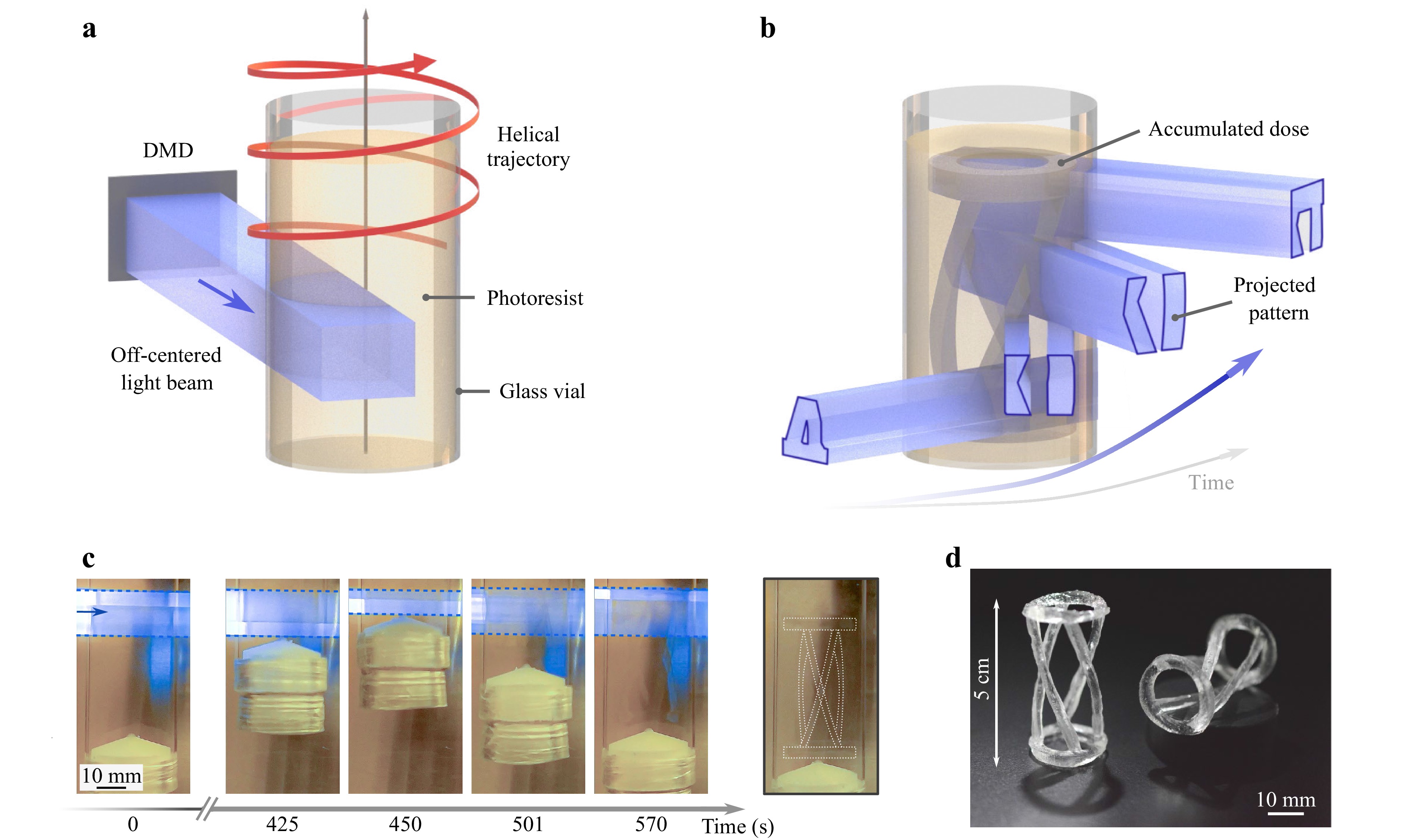
Fig. 1 Principle of tomographic volumetric helical additive manufacturing (VHAM). a Simplified schematic of the helical printer. A laser beam (λ = 405 nm) is modulated in intensity with a DMD before propagating through the photoresist. The vial containing the latter is off-centered, such that one lateral edge of the rectangular beam intersects the center of the cylindrical container. The vial is placed in rotation and move continuously up and down defining a helical trajectory. b Schematic representation of the helical printing procedure. A series of patterns of light projected over multiple angles trigger at different time the polymerization. At a given time only a subpart of the resin is exposed to light. In fact, it is the helical movement that ensures the solidification of the whole object. c Time lapse. Two cycles up/down and 12 turns were necessary to solidify the resin in the desired geometry (see 3D model in b). This is achieved in less than 10 min. The rotation stage holds the vial by the bottom. A white cap prevents resin’s leakage to the outside. d Final part obtained after washing out the unpolymerized resin. Scale bar: 10 mm.
The principle of tomographic Volumetric Helical Additive Manufacturing (VHAM) is given in Fig. 1a. We combine a rotating and a linear translation stages to set the glass vial (diameter = 32 mm) containing the photoresist in a helical motion. We must emphasize here that all the resin is not illuminated at once as in conventional tomographic VAM. Here, in VHAM, the whole resin is entirely excited only after one complete cycle comprising a bottom-up and a top-down pass. Half a cycle (only up or down) includes α rotations of the vial. As the vial follows a helical trajectory, α also represents the number of patterns stacked along the vertical axis. There are some overlapping regions between the patterns so that after a turn its lower and upper parts coincide. The size of the overlap is fine-tuned by adjusting the vial’s rotation speed to the vertical movement of the translation stage, which is essential to ensure continuity of the printed objects. A detailed workflow regarding the computation of the VHAM patterns is provided in Methods and Fig. S5. In this work, the rotation speed is between 8 and 10°∙s−1 which respectively gives a vertical linear speed of 458 μm·s−1 and 366 μm∙s−1. After a few up and down cycles, the light dose accumulated inside the resin at different heights and over multiple angles is sufficient to solidify it as shown on the schematic Fig. 1b. This usually happens after 2 or 3 vertical cycles and is in general completed in less than ten minutes (Fig. 1c). Note that because of light absorption, patterns projected at θ and θ+180° do not irradiate the volume of resin in the same way. We take this into account by performing a blank half turn (simply put, no projection and no vertical translation over 180°) between two vertical cycles. Without this blank half turn, the deposited light dose would not be diametrically symmetrical, although this could be compensated numerically (to some extent)18. It results that for 3D structures with no central symmetry, the number of projected patterns doubles. To give an idea, one may need to project around 10,000 patterns for printing with α = 3 and an angular resolution of 0.18°.
The final 3D printed structure is obtained after some post-processing including a washing and post-curing steps as described in Methods. For the helical tower structure in Fig. 1d, α = 3; which means 4α = 12 times more printable voxels inside the resin compared to conventional tomographic VAM.
-
We report on the capabilities of helical tomographic VAM through a series of different printed structures in transparent acrylics. The photo-curable resin used in this work is prepared by combining a commercial polyacrylate (PRO21905 from Sartomer), with 0.6 mmol phenylbis (2, 4, 6-trimethylbenzoyl) phosphine oxide as a photoinitiator in a planetary mixer. The optical transparency together with its stiffness and ease of use makes it a candidate of choice to present our printer’s competences in terms of object size and resolution. In Fig. 2, we show the prints of five different 3D models, relatively large (2 cm wide at least), with different heights. For all of them, the DMD is off-centered with respect to the vial’s rotation axis, but the parameter α is adjusted to fit the height of each object. As in conventional tomographic VAM, these complex and hollow geometries are printed in a short time (3-10 minutess, indicated on the figure) without the need for support structures.
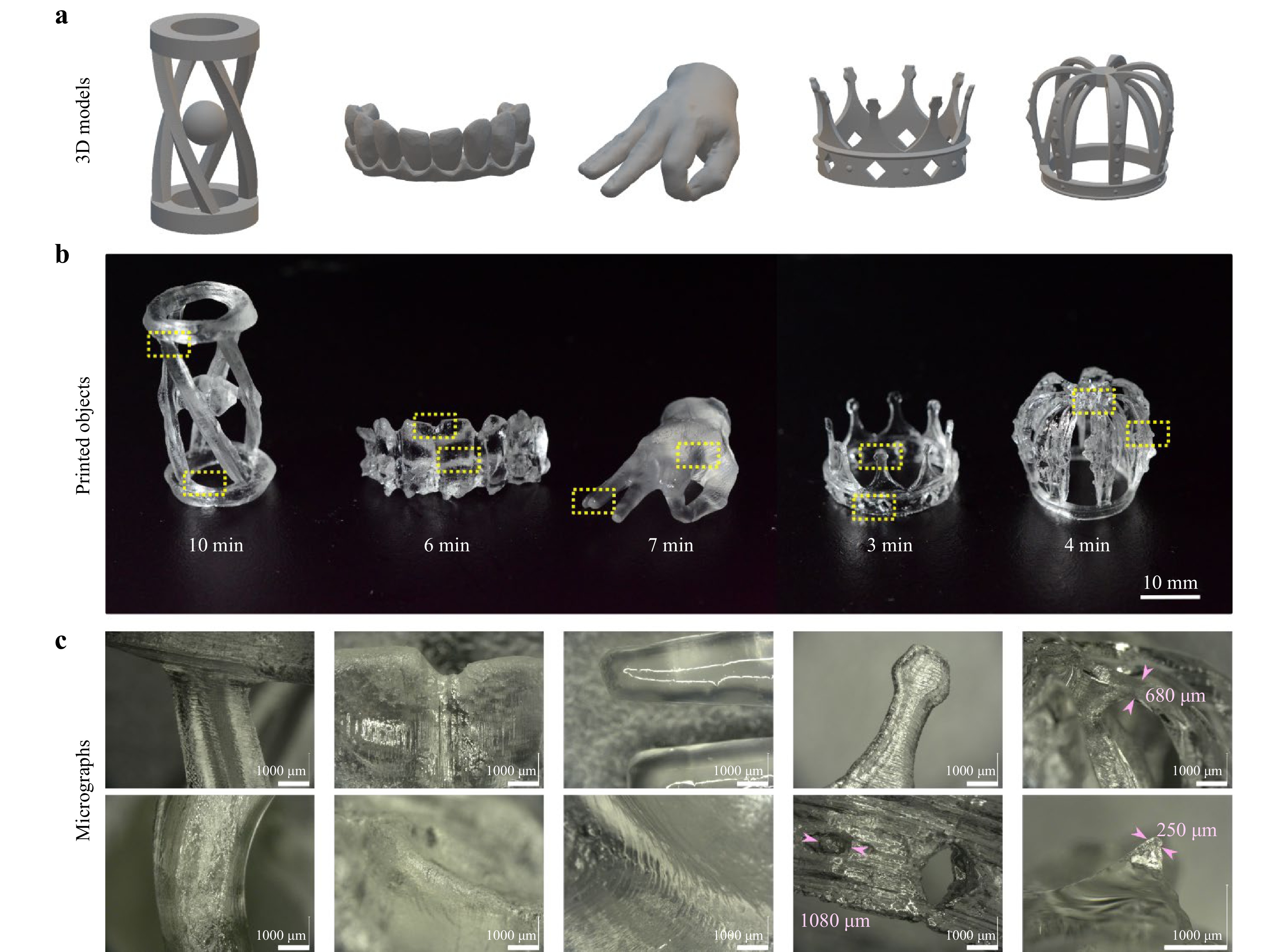
Fig. 2 Examples of 3D printed objects using tomographic VHAM. a 3D model. b Photographs of the obtained prints, with their printing time indicated in minutes. c Microscopic images of some details of the prints. Scale bars: b = 10 mm, c = 1 mm.
The absence of layering offers excellent surface quality as one can see in the micrographs in Fig. 2c, especially for the prints of the hand and the teeth. Striations, similar in appearance to a few tens of microns thick layers, can be observed. They are caused by a self-induced waveguide effect, driven by the nonlinearity of the material’s gelation and can potentially be removed28. Suspended complex structures as thin as the 680 μm double arches of the crown and its 250 μm spikes in relief can be printed with high fidelity. The printer is not only capable of printing sharp edges like the square pillars of the helical tower but also round and curved surfaces like the circular base of the structure. We also report on the possibility of printing in a few minutes optically-clear models of teeth with high resolution, as shown in Fig. S3. The speed of the process and the achieved level of details might make helical tomographic VAM interesting for dental industry. However, resolution must be improved before the technique can be widely adopted in industry. We also explored the effects of beam quality on print fidelity.
Effects of optical features of the beam on print fidelity
Beam divergence
We investigated the effect of the beam divergence on the resulting dose deposited inside the build volume using computer simulations. Two different configurations were considered: on the one hand the DMD is on-axis and illuminates the whole volume of photoresin (as in conventional tomographic VAM) and on the other hand the DMD is off-centered as in VHAM (Fig. 3). As a result, the way the DMD is positioned with respect to the cylindrical vial does not change much the obtained dose. In both cases the divergence results in a global blur of the light dose. The effect is stronger on the edge as the voxel size due to divergence is larger. The beam divergence is modified by adjusting the Rayleigh range of the optical beam zRayleigh. Shorter zRayleigh corresponds to high beam divergence.
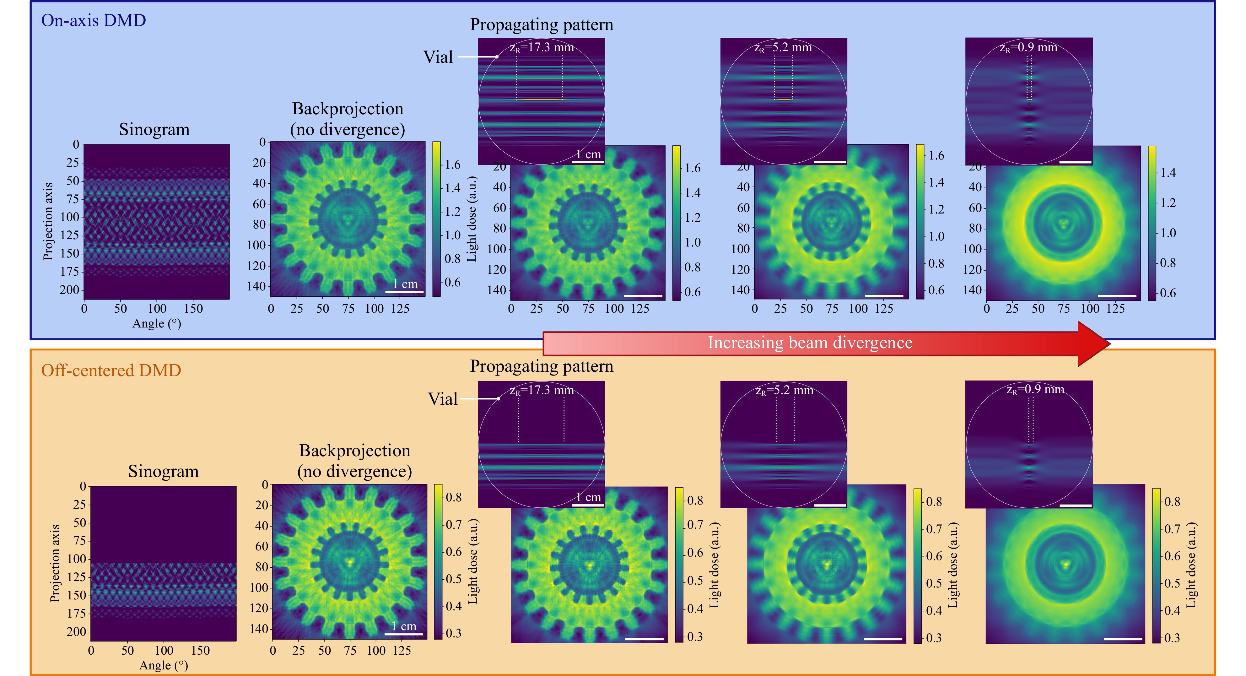
Fig. 3 Effect of beam divergence on the resulting dose for a flat gear with inner and outer cogs as a resolution target (Fig. S6). In tomographic VAM, the DMD illuminates the entire printing vial. In the proposed VHAM, the DMD is off-centered with respect to the optical axis. If the magnification of the projecting optical system is kept, off-centering the DMD allows to double the diameter of the printable objects.
Beam defocusing
A defocused divergent beam also affects the resulting dose deposited inside the build volume. We considered the on-axis and off-centered DMD again. This time the way the DMD is positioned with respect to the cylindrical vial radically changes the obtained dose. Whereas the divergence results in a global blur of the light dose, a defocus in the case where only half the vial is illuminated translates into artifacts/drifts (Fig. 4). The effect is stronger on the edge as the voxel size due to divergence is larger, hence the effect of defocusing magnified. The beam defocusing is modified by adjusting position of the focal plane with respect to the rotation axis of the vial. When printing the gear as a print-fidelity target, we realize that beam defocusing explains artifacts that resemble rotational drift.
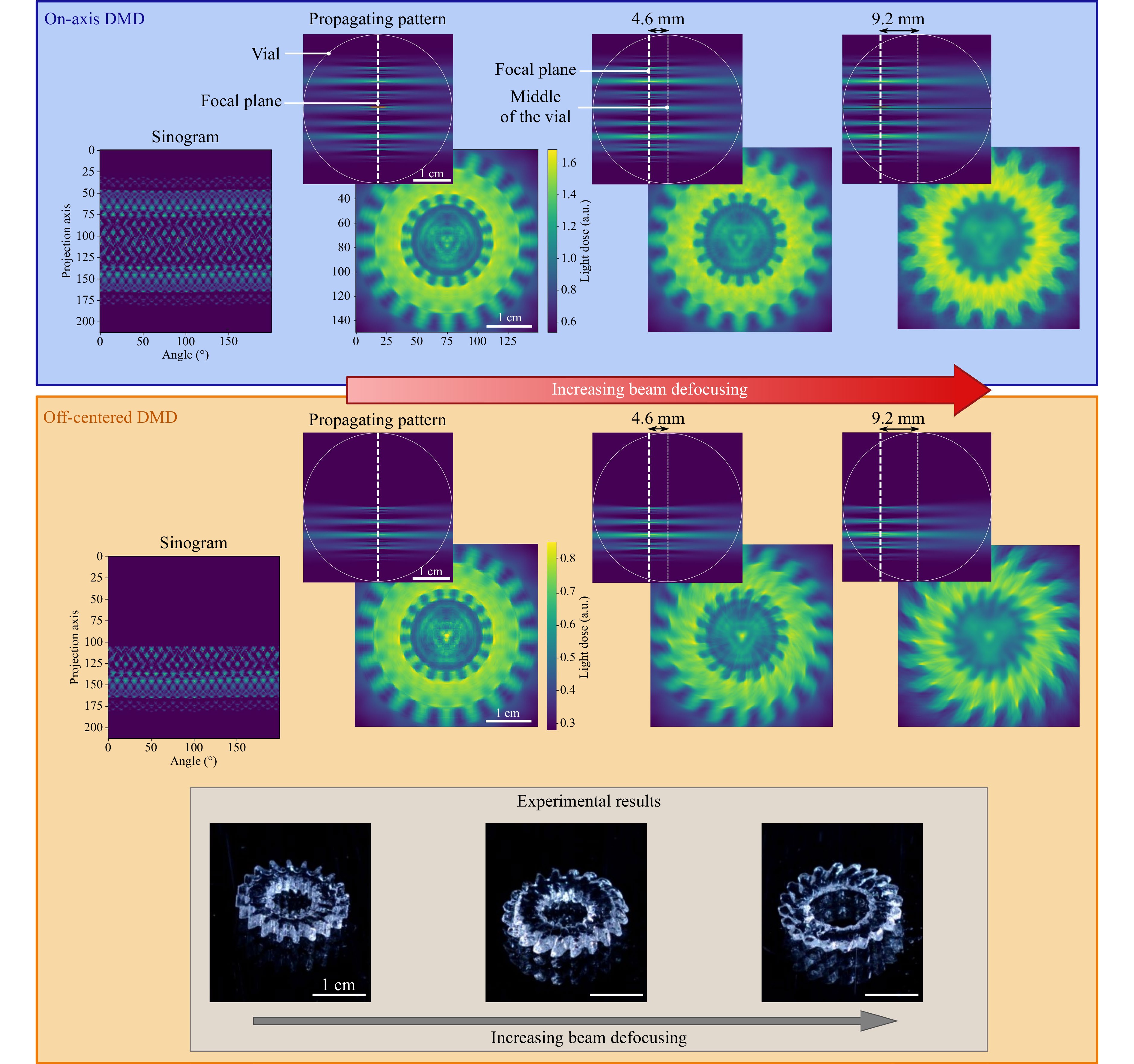
Fig. 4 Effect of Beam defocusing on the resulting dose. For tomographic VAM setups in which the DMD is centered with the optical axis (top panel, in blue), beam defocusing compromises contrast and resolution of the print, but not on the symmetry of the prints, as shown in the simulations. (top row) Top views of a tomographic pattern from the sinogram of a gear with outer and inner cogs, with the focal plane of the projected beam falling on the center of the vial, 4.6 mm, and 9.6 mm from it (zRayleigh = 5.2 mm). Resulting deposited light doses once the complete sinogram is projected for the different defocusing scenarios (bottom row). On the contrary, when the DMD is placed off-centered from the optical axis (bottom panel, in orange), defocusing of the beam translates into asymmetries in the print. Photographs of resulting 3D printed gears, matching the computer simulations. All scale bars = 1 cm.
-
Having a look at conventional tomographic VAM, one rapidly foresees the advantages related to the helical motion. Usually in tomographic VAM, the available Nx × Ny pixels of the DMD illuminate the whole rotating volume of resin at once, as represented in Fig. 5a. In theory this configuration provides π/4 Nx2 × Ny independent printable voxels. Off-centering the DMD doubles the lateral resolution or increases the number of printed voxels by a factor of 4. Additionally, the continuous translation of the vial gives the possibility of printing taller objects (see Fig. 5b). The increase in the vertical direction is described by the parameter α.
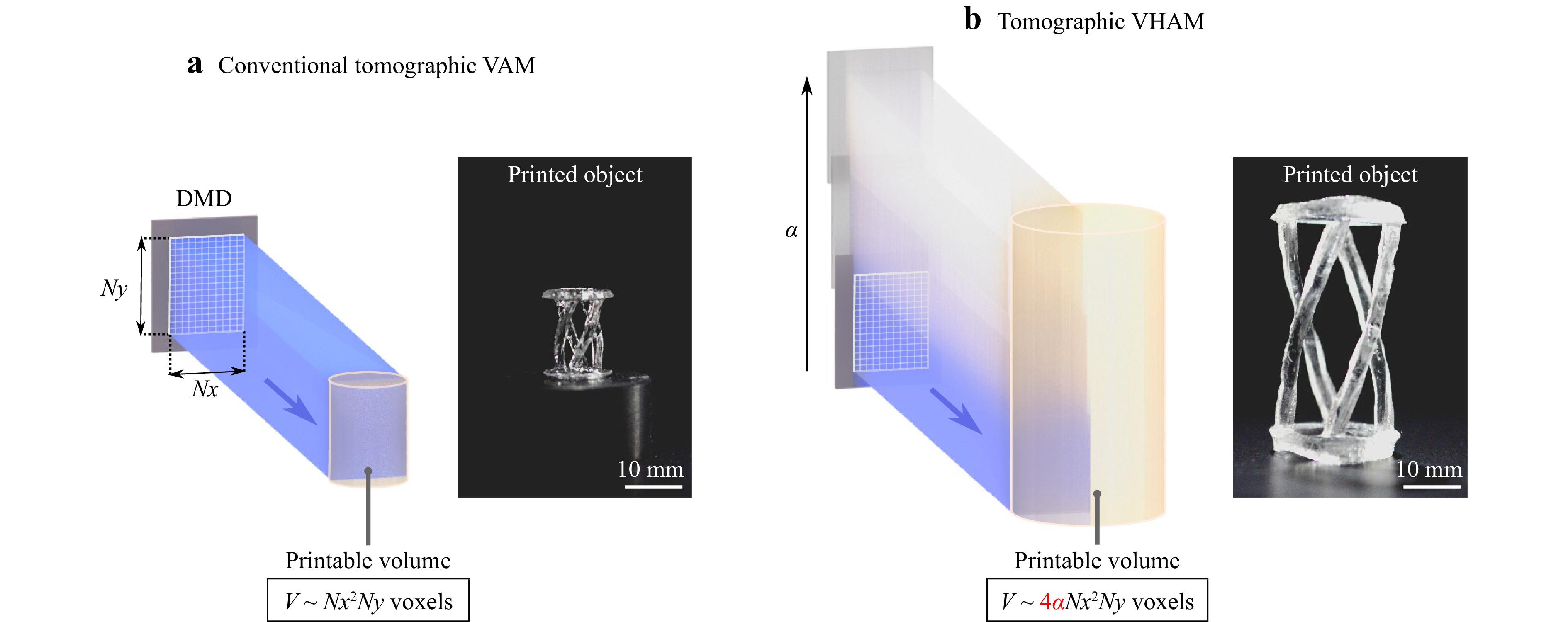
Fig. 5 Increasing the number of printed voxel generated from the same DMD. a Conventional tomographic volumetric additive manufacturing. b Tomographic volumetric helical additive manufacturing. Scale bars: 10 mm.
In this work, we printed objects with α up to 3, meaning objects 3 times taller. Overall, this new optical configuration increases the number of printed voxels inside the vial by a factor up to 4α = 12 compared to conventional tomographic VAM, see Fig. 5. This size increase is at the cost of the printing speed since the resin must be exposed to light for a longer time to reach the threshold dose. It is possible to lower the threshold dose by increasing the concentration of photoinitiator, but one must be careful not to make the resin too absorptive, or by increasing the laser power.
As in any light-based VAM methods, printing larger structures comes at least with two challenges. On the one hand, light has to penetrate deeper inside the resin to cure the whole volume; light absorption is therefore more critical. On the other hand, light has to propagate straight over longer distances. Whatever the printing technology, light is never perfectly collimated and divergence can be at the origin of strong deviation between the model used for computing the patterns and the real experiment15,19. In our case, we deliberately chose to reduce the numerical aperture of our optical projection system to reduce the beam divergence in order to preserve the printing fidelity although it is at the cost of the resolution and printing speed since we cut part (the high spatial frequencies) of the incoming light. We provide in the supplementary materials a characterization of the beam divergence in our VHAM printer and the effect of the numerical aperture, divergence and defocusing on print quality (Figs. 3, 4 and Figs. S1, 2) through a numerical model . Additionally, we explore the possibility of using VHAM to fabricate dental models (Supplementary S.5). Although divergence inevitably affects print resolution, we successfully printed features size of 680 μm for objects as big as 2.5 cm × 2.5 cm × 3 cm (see in Fig. 2c).
We expect similar resolution for objects taller than 3 cm (for a greater α) since the vertical motion should not affect resolution. For comparison, we calculate that a modified version of CAL using an LED instead of a laser diode would probably provide a resolution around 700 μm for objects of the same size. To further improve the printing resolution it could be interesting to use a better model for computing the light patterns (for instance by including the divergence of the beam) or getting feedback from the printing process15,29,30. Note that the comparison between these different techniques we propose in Supplementary Table 1 should not be taken literally, mainly because the photoresist used in each case is different. It is well-known that the chemical system plays an important, or rather essential role with regards to the obtained resolution. In particular, the spatial resolution can be improved from the previously reported value, by intentionally introducing radical quenchers in the resin besides oxygen that naturally acts as inhibitor of free-radical polymerization. In terms of printing time, helical VAM is comparable with xolography for similar object sizes; however using thiol-ene photoresins, instead of acrylates, should drastically reduce printing time25,31, and consequently resolution32. Both helical VAM and xolography seem to offer competitive capabilities but their working principles remain different, and depending on the target structure or material used one might offer better results than the other.
In summary, we have presented a proof-of-concept of a new light-based technique for volumetric printing of multi-centimeter scale objects. It builds up on tomographic VAM to significantly increase (up to a factor 12) the number of printable voxels while keeping the same light modulating device for projection and without compromising too much the printing resolution. This was achieved by off-centering the light modulator and translating continuously the resin vertically along the patterned light beam. These simple modifications can be easily made on existing tomographic printers and opens up new possibilities for high-resolution and high-speed fabrication of objects whose size up to 3 cm × 3 cm × 6 cm. Helical tomographic VAM might be therefore appealing for applications in fields where cm-scale objects must be manufactured individually, such as in the dental industry (Fig. S3), although resolution must be improved to meet the current requirements of the industry.
-
The optical setup for tomographic VHAM is presented in Fig. S4 . Two 405 nm laser diodes, with a combined nominal power of 1.8 W, are collimated and combined into a single beam with a D-shaped mirror (Thorlabs, BBD05-E02). The combined beam is then coupled into a square-core optical fiber (CeramOptec WF 70 × 70/115/200/400 N, core size 70 μm by 70 μm, numerical aperture 0.22), in order to spatially homogenize the beam from the two laser diodes. The outgoing square beam is then magnified to match the rectangular aperture of the DMD (Vialux, V-7000 VIS) via an aspheric lens L3 and a set of two orthogonal cylindrical lenses L4 and L5 for maximizing the light efficiency. Note that the cylindrical lenses have different focal lengths (f4 = 250 mm and f5 = 300 mm), in order to adjust the square beam from the fiber square output facet to the rectangular area of the DMD. The DMD suffers from diffractive effects due to the blazed grating formed by the micromirrors (pitch = 13.6 μm). This effect can cause a large fraction of the reflected light to be lost in diffracted orders depending on the incidence angle of the illumination beam. The surface of the DMD is imaged via a 4f system into a cylindrical glass vial containing the photopolymerizable resin. In the Fourier plane (between L6 and L7), an iris blocks the unwanted diffraction orders from the DMD. This iris also effectively controls the numerical aperture of the beam, and its aperture can be adjusted to balance beam width and Rayleigh length. A refractive-index matching bath of vegetable oil is used to remove the lensing distortion caused by the cylindrical interface of the vial30,33. Compared to conventional tomographic VAM, the DMD is off-centered with respect to the vial’s rotation axis and the resin can be moved vertically thanks to a linear stage with a travel range of 10 cm (Zaber, LSQ075A). A side view camera placed perpendicular to the optical axis monitors the printing process. A red LED that does not influence the photopolymerization is used for this purpose (Thorlabs, M660L4-C5).
-
The computation of the light patterns from the 3D model target dose relies essentially on the Radon transform as developed for tomographic imaging (Fig. S5). However in the case of printing, the problem to solve is reversed: one has to compute the 2D patterns from the 3D dose whereas in imaging the algorithm aims at reconstructing the 3D object from a set of 2D measurements. As in tomographic VAM13,34 the starting point is the 3D model, i.e. the object one intends to print. The latter is first voxelized into a three-dimensional binary matrix, where the entries “1” indicate the presence of matter and “0” its absence at each particular location in space. The voxel size depends on the optical setup and is in our case around 23 μm. The dimension of the matrix is therefore given by the target object size divided by the voxel size. This matrix also represents the normalized target dose that one would need to deposit in a transparent resin to polymerize it in the desired geometry. A series of dose projections over multiple angles are calculated from the Radon transform. More precisely, the patterns are obtained using a filtered back-projection algorithm followed by an optimization subject to positivity constraint. Please note that this forward model assumes the use of optically-clear materials, in which light propagates straight and without attenuation. The obtained patterns are too large to be entirely projected with the DMD. For these reasons they are cropped twice. First, along the horizontal axis, because the DMD is off-centered and second vertically to account for the up and down moving of the vial. These two crops allow for reducing the image size to a pattern that can be projected onto the DMD. To avoid any printing discontinuity along the vertical direction the patterns are softened on the corresponding edges with a smoothing mask that contains an overlapping region of adjustable height. The last step consists of padding with zeros the patterns to fit the DMD size.
-
A liquid pentaacrylate commercial resin (PRO21905, Sartomer) was mixed with 0.6 mmol phenylbis (2, 4, 6-trimethylbenzoyl) phosphine oxide as a photoinitiator (TPO, Sigma Aldrich) in a planetary mixer. The mix was poured into 32 mm cylindrical glass vials, and bubbles were removed by intermittent sonication for about an hour. Printing was performed at room temperature. Under these conditions, the resin has a viscosity of 20 Pa·s. Given the printing times in the order of minutes, high viscosity is necessary to prevent the sinking of the object to be detrimental to print fidelity15,32.
In order to rinse the printed objects after printing, they were gently taken from the vials with a spatula, immersed in 50 mL falcon tubes containing isopropyl alcohol, and sonicated for several minutes at room temperature. Objects were post cured immersed in glycerol in a curing chamber (Formlabs, Form Cure) under UV light to remove the stickiness of their surface.
-
This project has received funding from the Swiss National Science Foundation under project number 196971 - “Light based Volumetric printing in scattering resins” European Union’s Horizon 2020 research and innovation programme under grant agreement No 964497. The authors thank the free or open-source tools (and their contributors) which were used in this work, including Tinkercad.com, FreeCADweb.org, Inkscape.org, Python.org, PyTorch.org, and Thingiverse.com.
Volumetric helical additive manufacturing
- Light: Advanced Manufacturing 4, Article number: (2023)
- Received: 03 November 2022
- Revised: 18 April 2023
- Accepted: 20 April 2023 Published online: 16 June 2023
doi: https://doi.org/10.37188/lam.2023.012
Abstract: 3D printing has revolutionized the manufacturing of volumetric components and structures for various fields. Thanks to the advent of photocurable resins, several fully volumetric light-based techniques have been recently developed to push further the current limitations of 3D printing. Although fast, this new generation of printers cannot fabricate objects whose typical size exceeds the centimeter without severely affecting the final resolution. Based on tomographic volumetric additive manufacturing, we propose a method for volumetric helical additive manufacturing (VHAM) multi-cm scale structures without magnifying the projected patterns. It consists of illuminating the photoresist while the latter follows a helical motion. This movement allows to increase the printable object’ s height. Additionally, we off-center the modulator used for projecting the light patterns to double the object’ s lateral size. We demonstrate experimentally the interest of using these two tricks for printing larger objects (up to 3 cm × 3 cm × 5 cm) with fine details (650 μm) and short print time (< 10 min).
Research Summary
Light-based 3D printing: spiral motion allows for bigger prints
3D printing of larger objects by continuous light projection is now possible. Tomographic volumetric additive manufacturing, a recent development in light-based fabricating technologies, produces objects truly volumetrically by projecting light patterns onto a rotating vial filled with a photo-curable material. Christophe Moser from Ecole Polytechnique Fédérale de Lausanne in Switzerland and colleagues extend the method to fabricate larger objects still in a layer-less fashion. Taking inspiration from spiral-CT, the authors used the continuous projection of light patterns coupled with a helical motion of the photo-curable resin to fabricate objects up to 32 mm in diameter and 100 mm in height. The printing strategy could open new possibilities for the rapid fabrication of larger prototypes or, possibly, dental models.
Rights and permissions
Open Access This article is licensed under a Creative Commons Attribution 4.0 International License, which permits use, sharing, adaptation, distribution and reproduction in any medium or format, as long as you give appropriate credit to the original author(s) and the source, provide a link to the Creative Commons license, and indicate if changes were made. The images or other third party material in this article are included in the article′s Creative Commons license, unless indicated otherwise in a credit line to the material. If material is not included in the article′s Creative Commons license and your intended use is not permitted by statutory regulation or exceeds the permitted use, you will need to obtain permission directly from the copyright holder. To view a copy of this license, visit http://creativecommons.org/licenses/by/4.0/.

 DownLoad: