


-
Optical three-dimensional (3D) imaging and measurement can perceive the real 3D world and accurately reconstruct the geometrical information of measured objects, which is essential in numerous applications1–4. Traditional optical 3D geometrical metrologies, such as fringe projection profilometry5, line laser scanning6, and binocular stereo vision7, follow point-to-point triangulation rules (under direct reflection and transmission conditions) and highly depend on each reflection point's intensity or phase information. However, when facing complex reflection conditions, such as interreflection for metallic surfaces and subsurface scattering for biological tissue, and complex transmission conditions8 including volumetric scattering medium and multi-layer semitransparent surfaces, the point-to-point triangulation rule is no longer applicable, which causes encoding information to be degraded and aliased. Irreparable errors occur in in-depth measurements and 3D imaging. However, the correct and fast perception of a complex environment is critical for many applications, such as online inspection in additive manufacturing9, autonomous driving10, and biomedical imaging11. Hence, there is an urgent need to develop reliable and adaptable dynamic 3D shape reconstruction techniques for complex reflection and transmission conditions.
There have been many prior works on achieving high dynamic range (HDR) measurements on multi-type surfaces with different reflection conditions from equipment and algorithm perspectives. Equipment-based methods focus on finding the optimal parameters to ensure high-quality encoding pattern acquisition with additional hardware such as polarizers12, multiple cameras13 or light field cameras14. However, the bottleneck of this type of strategy is cost increase and intensity or resolution loss. The recently developed event camera-based structured light (SL) technique can realize a very high dynamic range (> 120 dB) measurement and can be applied in broad illumination conditions15,16. However, its asynchronous data acquisition mode and immature reconstruction algorithm limit its measurement resolution and accuracy at the current stage. Instead, algorithm-based methods seek to extract depth information from unsatisfactorily captured raw data by relying on well-designed algorithms17. Adaptive SL methods have been developed, and adaptive illumination patterns with varying intensities or multiple exposure shooting have been utilized to fuse fine results for objects with different reflectivity17,18. However, determining the adaptive illumination pattern and exposure time depends on the illumination and reflectivity of the unseen measured scenes, making applying this method to time-varying dynamic scenes challenging. Moreover, recently emerging deep learning-based methods have been developed to retrieve depth from overexposure patterns19,20 or enhance a single exposure-captured low-illumination pattern21,22 based on numerous datasets. The above-mentioned methods can realize HDR measurement on multi-type surfaces but fail to deal with indirect reflection (interreflection) and transmission (through scattering media) conditions because they still obey the point-to-point triangulation rule.
For 3D reconstruction under indirect reflection and transmission conditions, Nayar et al. found that high-frequency patterns resist interreflections23 and Gupta et al. proposed a micro phase shifting method to reduce the influence of the indirect reflection illumination component24. A similar idea was used in binary coding SL by introducing logical operations to convert low-frequency code into high-frequency one25. However, these methods assume that only low-frequency indirect illumination exists, which fails when highly specular or refractive surfaces are encountered. A more general solution for separating complex illumination is to establish a light transport equation that directly describes the propagation path of each light source. O’Toole et al. proposed primal-dual coding to probe light transport by projecting a sequence of patterns onto a scene while a sensor was exposed to light only once26. This technique can accurately describe the complex transmission process between the projector and camera pixels and can be applied for flexible illumination, imaging, and 3D shape measurement under indirect illumination27,28. However, this method required to build a well-designed coaxial DMD-based camera.
Recently, the emerging single-pixel imaging (SI) technique has proven to be a promising and powerful tool for solving inverse problems29,30 and has been demonstrated in terahertz imaging31,32, infrared imaging33,34, 3D imaging35,36, and imaging through complex scattering media37,38. SI produces images by illuminating a scene with a series of spatially resolved patterns while collecting the correlated intensity using a detector without spatial resolution. This unique working mechanism provides point-to-plane imaging ability. Inspired by this, Jiang et al.39 proposed a parallel single-pixel imaging (PSI) technique, in which the SI technique is introduced in array cameras to separate direct and global illumination without any extra hardware cost. However, numerous Fourier basis patterns are required for one reconstruction40 and local regional assumption is required, which makes this technique unable to perform dynamic measurement41.
In this study, we develop a dynamic 3D shape reconstruction method under complex transmission and reflection conditions based on multi-scale parallel single-pixel imaging (MS-PSI). A Fourier dual-slice projection with depth-constrained localization (FDPDL) is presented to efficiently separate and utilize different illumination and reflection components, which can significantly decrease the number of required projection patterns in each sequence from thousands to 15. Then, MS-PSI is proposed based on the established and proven position-invariant theorem, which breaks the local regional assumption. We demonstrated that MS-PSI can achieve depth measurements on multi-type surfaces, including metal and wax, with interreflection and subsurface scattering. We also demonstrate the unseen capabilities of 3D imaging through dynamic mist and a semitransparent surface with a hidden object behind it. The proposed method provides a general and efficient solution for dynamic 3D reconstruction under complex transmission and reflection conditions and has a sustainable impact in basic science and engineering application domains.
-
In traditional 3D geometric metrology based on triangulation, accurate shape reconstruction is based on the direct reflection condition, as indicated by the yellow rays in Fig. 1a. However, actual measurements often suffer from complex reflection and transmission conditions such as interreflection (blue rays), subsurface scattering (green rays), and volumetric scattering (brown rays), as shown in Fig. 1a. All the reflection components were mixed and captured by the same pixel in the camera. It breaks the point-to-point mapping relationship between the projecting and imaging planes and causes an ill-posed problem in shape reconstruction. The MS-PSI technique was developed to overcome this problem and achieve dynamic 3D measurements under mixed illumination, as shown in Fig. 1.
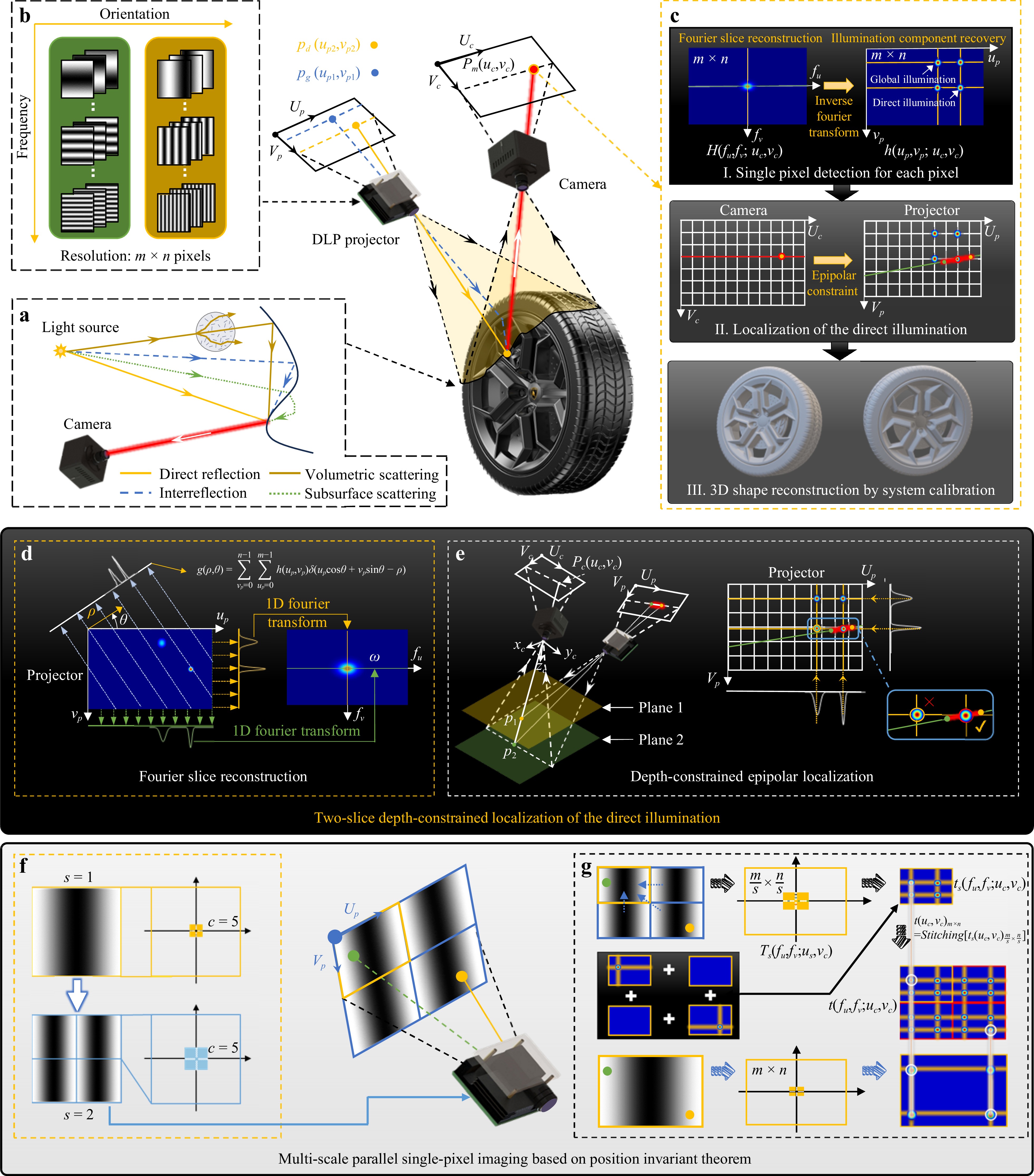
Fig. 1 Schematic diagram of MS-PSI for dynamic 3D shape measurement under global illumination. a Illumination components in global illumination. b Projected Fourier basis pattern in MS-PSI. c 3D reconstruction process of MS-PSI algorithm. d Illustration of Fourier slice reconstruction. e Illustration of depth-constrained epipolar localization. f Regeneration of multi-scale projecting patterns. g Illustration of position invariant theorem.
In MS-PSI, vertical and horizontal Fourier basis patterns are projected, as shown in Fig. 1b, and every camera pixel is treated as a single-pixel detector to retrieve the 2D light transport coefficient h(up,vp; uc,vc) between pixel (uc,vc) and the projector pixel (up,vp) using the Fourier single-pixel imaging (SI) algorithm40 and Fourier slice theorem, as shown in Fig. 1c. The point-to-plane imaging capability of the SI enables the solved h(up,vp; uc,vc) to separate the direct and global illumination components in the projection plane for a specific camera pixel (uc,vc). After the depth-constrained epipolar location, a unique corresponding relationship between the projecting and imaging planes can be established, and accurate 3D shape measurements can be achieved under mixed reflection and transmission conditions.
For the traditional PSI algorithm, the number of required Fourier basis patterns for one reconstruction is N × m × n × r/2 (N is the phase-shifting step, m and n are the camera resolution, r is the sampling ratio); for example, when N = 4, m = n = 1024, r = 0.25, 524288 projected patterns are required, which is very large in actual measurement and significantly limits the measurement speed. The theoretical basis of the PSI algorithm is described in Supplementary Note S1. Improved techniques such as the LRE and projective PSI methods have been proposed to reduce the number of projected patterns to 33641. However, the local and regional assumptions require updating the projection patterns with varying illumination conditions, as discussed in Supplementary Note S2. Thus, the existing studies have only applied the PSI technique to static scenes.
Herein, FDPDL is presented to locate direct illumination using only two spectral slices, which can significantly decrease the number of projected patterns in each sequence to 15. Next, MS-PSI is proposed to improve the sampling efficiency further and optimize the location accuracy with fixed pattern projection, which breaks the local regional assumption.
In the FDPDL, a three-step phase-shifting Fourier basis pattern projection is adopted, and only vertical and horizontal Fourier basis patterns are projected. The core objective of PSI is to locate the light transport coefficient rather than imaging. Based on this point, the Fourier slice theorem can be introduced to improve the measuring efficiency41. As shown in Fig. 1d, the Radon transform is used to project the light transport coefficient h(up,vp; uc,vc) onto a 1D projection line g(ρ,θ; uc,vc) along the line determined by direction θ and distance ρ to the origin
$$ g(\rho ,\theta ;{u_c},{v_c}) = \sum\limits_{{v_p} = 0}^{n - 1} {\sum\limits_{{u_p} = 0}^{m - 1} {h({u_p},{v_p};{u_c},{v_c})} } \delta ({u_p}\cos \theta + {v_p}\sin \theta - \rho ) $$ (1) According to the Fourier slice theorem, the 1D Fourier transform of g(ρ,θ; uc,vc) equals the 2D Fourier slice of h(up,vp; uc,vc) through its origin, which is parallel to the projection line
$$\begin{aligned} G(\omega ,\theta ;{u_c},{v_c}) =\;& \sum\limits_{\rho = 0}^{m - 1} {g(\rho ,\theta ;{u_c},{v_c}){e^{ - j2\pi \omega \rho }}} d\rho \\=\;& {[H({f_u},{f_v};{u_c},{v_c})]_{{f_u} = \omega \cos \theta ;{f_v} = \omega \sin \theta }} \\=\;& H(\omega \cos \theta ,\omega \sin \theta ;{u_c},{v_c})\end{aligned} $$ (2) In which, ω denotes the Fourier transform of ρ. Thus, the complete spectrum reconstruction can be converted into a collection of two slices. The direct and global components can be located in the projecting plane through the back projection to find the center of the intersection, as shown in Fig. 1d. However, if only two Fourier slices are reconstructed, additional ambiguous points will appear in the back-projection image. Hence, standard planes at the closest and farthest locations within the measuring range were used to generate length-limited epipolar structures and eliminate incorrect points outside the defined measuring range, as shown in Fig. 1e. For any camera pixel, two points can be located in the projecting plane, and direct illumination lies on the connecting line between these two points in the measuring volume. In this manner, the search area for direct illumination can be constrained to a short line, which can avoid ambiguous points in dual-slice localization and accelerate the search process. The implementation of depth-constrained localization is shown in Supplementary Note S3.
We first established and proved the position-invariant theorem to improve the sampling efficiency further and break the local and regional assumptions in dynamic measurements.
Position invariant theorem: If the projecting patterns are equally divided and regenerated into subregions with any scale in PSI, the location of the detected direct illumination component remains unchanged in the reconstructed image using MS-PSI. This was proven by the derivation of the formula in Supplementary Note S4.
MS-PSI was proposed based on the position-invariant theorem. The projecting plane was equally divided into s × s subregions (s is the scale factor). The projecting Fourier basis patterns were resized and duplicated in each subregion, as shown in Fig. 1f. The updated two-directional Fourier base patterns are projected sequentially. When the projected light is captured by each camera pixel, the sub-region is treated as a reconstruction unit to retrieve the light transport coefficient. Thus, although the number of unidirectional Fourier coefficients c remained the same, the size of the reconstructed region decreased significantly. Therefore, the sampling ratio and reconstruction quality can be improved by increasing the number of subregions s2. The position-invariant theorem indicates that an extra periodic illumination component occurs in the reconstructed image; however, the location of the detected direct illumination does not change, as shown in Fig. 1g. Therefore, even if the location of the illumination component exceeds the local region, the direct illumination can still be accurately located using FDPDL. Hence, a small number of fixed generated illumination patterns can be projected for dynamic measurements, breaking the existing methods’ local region assumption.
-
In MS-PSI, the projecting plane is divided equally into s×s subregions, and the projecting Fourier basis patterns are resized and duplicated in each subregion, as shown in Fig. 2a. Following dual-slice pattern projection, the updated Fourier basis patterns with frequency ωs (ωs=s·ω) are projected sequentially, as shown in Figs. 2b−e. When the projected light is captured by each camera pixel, each subregion is treated as a reconstruction unit to retrieve the light transport coefficient. Therefore, the Fourier slice coefficient in the subregion can be described as
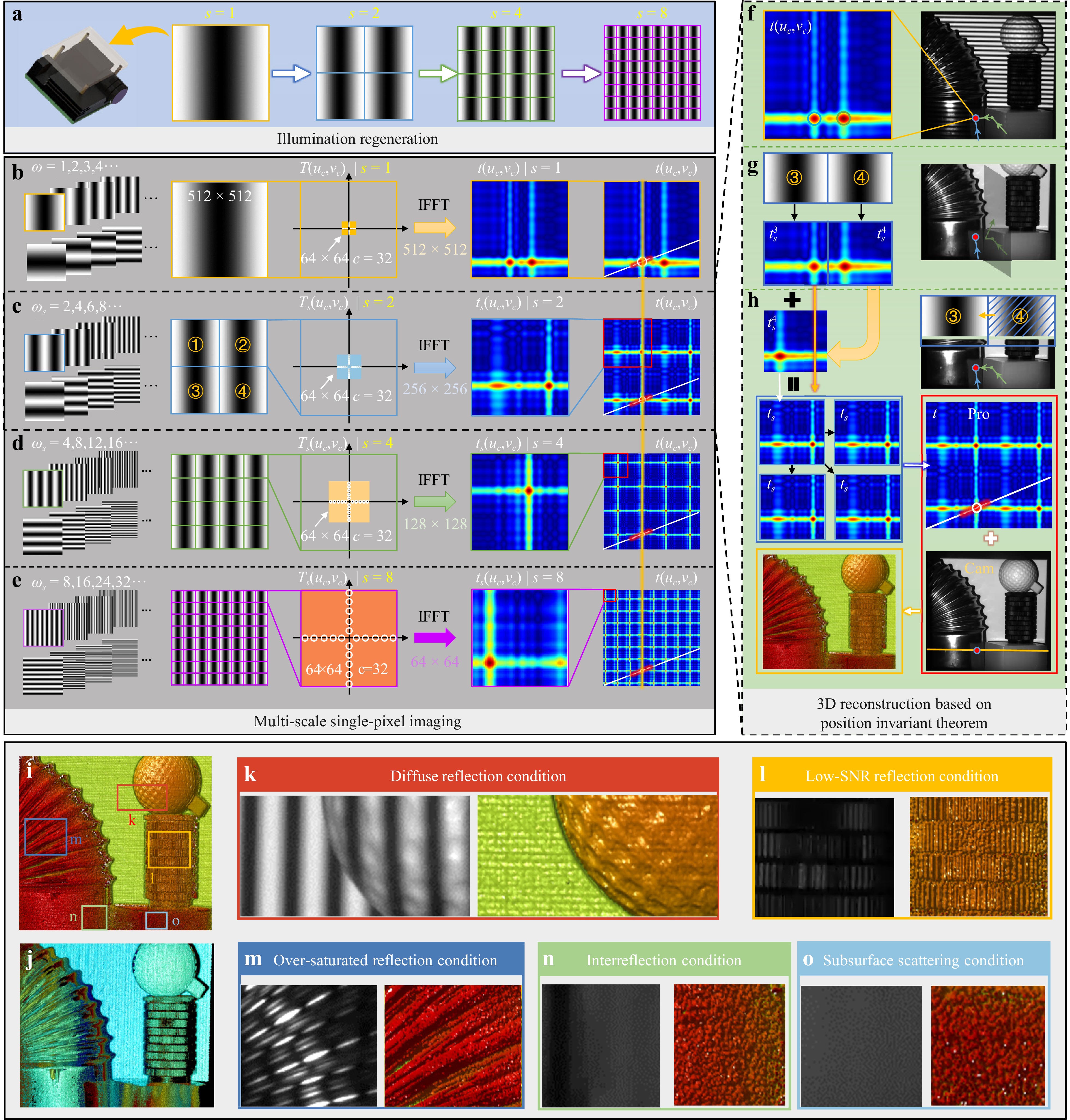
Fig. 2 Measurement of the complex scene with multi-type surfaces under global illumination. a Regenerating fixed projecting patterns in MS-PSI. b−e, MS-PSI reconstruction process when the scale factor s is 1, 2, 4, 8, respectively. f Reconstructed result for a single pixel in actual measurement when s = 1. g Subregion reconstructed result for a single pixel in actual measurement when s = 2 and assuming no inter-reflection exists. h Reconstructed process and result in actual measurement when s = 2 and inter-reflection exists. i Reconstructed depth map by MS-PSI. j Reconstructed depth map by FPP. k−o Regional fringe pattern and reconstructed result under diffuse reflection, low-SNR reflection, over-saturated reflection, interreflection and subsurface scattering condition, respectively.
$$ {G_s}({\omega _s},\theta ;{u_c},{v_c}) = G(s \cdot \omega ,\theta ;{u_c},{v_c}) $$ (3) Thus, the reconstructed spectrum Ts(fu,fv; uc,vc) in the subregion can be further obtained by adding two Fourier spectrum slices
$$ \begin{aligned}{T_s}({f_u},{f_v};{u_c},{v_c}) =\;& \left[ {{G_s}({\omega _s},{{90}^ \circ };{u_c},{v_c}) + {G_s}({\omega _s},{0^ \circ };{u_c},{v_c})} \right] \cdot\\& {W_s}({f_u},{f_v}) \end{aligned}$$ (4) where the filtering window Ws(fu, fv) denotes limited spectrum sampling in the actual coefficient acquisition. Finally, the generalized light transport coefficient ts(up,vp; uc,vc) in subregion is reconstructed as follows
$$ {t_s}({u_p},{v_p};{u_c},{v_c}) = {F^{ - 1}}[{T_s}({f_u},{f_v};{u_c},{v_c})]/2b $$ (5) in which b is the contrast of the projected fringe pattern.
It should be noted that ts(up,vp; uc,vc) is the superposition of the projection lines of the light transport coefficient hs(up,vp; uc,vc) along the vertical and horizontal directions, whose intersections contain light transport information. Therefore, it is defined as the generalized light transport coefficient. Because all the subregions shared the intensity detected by the same camera pixel, the reconstructed ts(up,vp; uc,vc) in different subregions were the same and could be directly duplicated and stitched to the full-field generalized light transport coefficient t(up,vp; uc,vc) using
$$ t{({u_p},{v_p};{u_c},{v_c})_{m \times n}}{\text{ = }}Stitching[{t_s}{({u_p},{v_p};{u_c},{v_c})_{\frac{m}{s} \times \frac{n}{s}}}] $$ (6) Thus, although the number of Fourier coefficients c (c = 32 in Fig. 2) at different scales remained the same, the size of the reconstructed region decreased significantly. Therefore, the sampling ratio and reconstruction quality can be improved by increasing s2 as shown in Fig. 2b−e. Comparative simulations of the traditional spectrum component optimization and MS-PSI optimization are provided in Supplementary Note S5.
MS-PSI with four subregions was applied to measure a challenging scene with multi-type surfaces, including highly reflective metal bellows, matte lens-mount adapters, a golf ball atop a white candle, and a diffuse ceramic plane background. One of the projected fringe patterns and the reconstructed light transport coefficient for the red point are shown in Fig. 2f. It can be found that the generalized light transport coefficient includes direct illumination (blue ray) and global illumination (green ray). In MS-PSI, the projected patterns are divided into four subregions, and the illumination components originate from subregions 3 and 4. If these two subregions can be independently considered, the reflected intensity information from the two subregions can be collected without interaction, and the subregion image can be completely preserved, as shown in Fig. 2g. However, all information from all the subregions is simultaneously collected by one camera pixel. If all illumination is assumed to originate from one subregion in MS-PSI, it is equivalent to periodically moving and merging all subregions into a unified coordinate system. Consequently, the retrieved image is a superposition of the generalized light transport coefficient for each subregion reconstructed by traditional PSI, as illustrated in Fig. 2h. Owing to periodic superposition, the position of the detected direct illumination remains unchanged in the stitched image. In addition, increasing the sampling ratio in MS-PSI makes the energy of direct illumination more concentrated in the stitched image, which can improve the location and benefit the final measurement accuracies. In fact, MS-PSI equally increases the spectrum sampling ratio by reducing the scale of the imaging region. This is discussed in detail in Supplementary Note S5.
After determining the pixel position in the projector coordinates for each captured pixel in the camera plane, 3D shape reconstruction can be performed through triangular stereo calibration42, as shown in Fig. 2i, with s = 8 and c = 10. In comparison, fringe projection profilometry (FPP), as a typical SL method, is used with a three-frequency, four-step phase-shifting algorithm (ωl = 1, ωm = 5, ωh = 20), in which 12 fringe patterns are required to reconstruct one result43. The depth map reconstructed by FPP is shown in Fig. 2j. This shows that reconstructed errors occur in the oversaturated and low-light regions, owing to the low measuring dynamic range of the traditional FPP. The reconstruction fails in the interreflection and subsurface scattering regions because it does not adhere to the direct reflection condition. The enlarged details under different reflection conditions are shown in Fig. 2k−o shows that MS-PSI can achieve shape measurements under complex reflection conditions. The inherent reason for the superiority of measurements under complex reflection conditions using the MS-PSI method is analyzed in Supplementary Note S6. The experimental results indicate the proposed method can perform 3D shape measurements on multi-type surfaces under complex reflection conditions.
-
The developed MS-PSI method significantly reduces the number of projection patterns and breaks the local region assumption; therefore, only dozens of fixed patterns are required, which enables dynamic measurements using PSI. A dynamic experiment was conducted on an impacted copper sheet. In this experiment, the key parameters s = 8 and c = 5 were determined by the trade-off between speed and accuracy, as shown in Supplementary Note S7. Therefore, Fourier basis patterns with horizontal and vertical directions were projected, and 5 groups of 3-step phase-shifting patterns with ωs = 8, 16, 24, 32, 40 were generated in each Fourier slice. Therefore, 30 (3 × 5 × 2 = 30) patterns are required to reconstruct one 3D result, which is an improvement of over ten-fold compared with the state-of-the-art PSI technique. Combined with the time-overlapping technique44,45, a new 3D result can be updated using only 15 patterns projected in each projection sequence. The synchronization rate of the high-speed camera and projector was 5000 Hz; therefore, the 3D reconstruction rate of the proposed technique was 5000/15 = 333 fps.
Fig. 3a shows the experimental setup, where a piece of copper sheet was fixed to the metal rack, and a motor-driven impact device moved forward to squeeze the copper sheet, as shown in Fig. 3b.
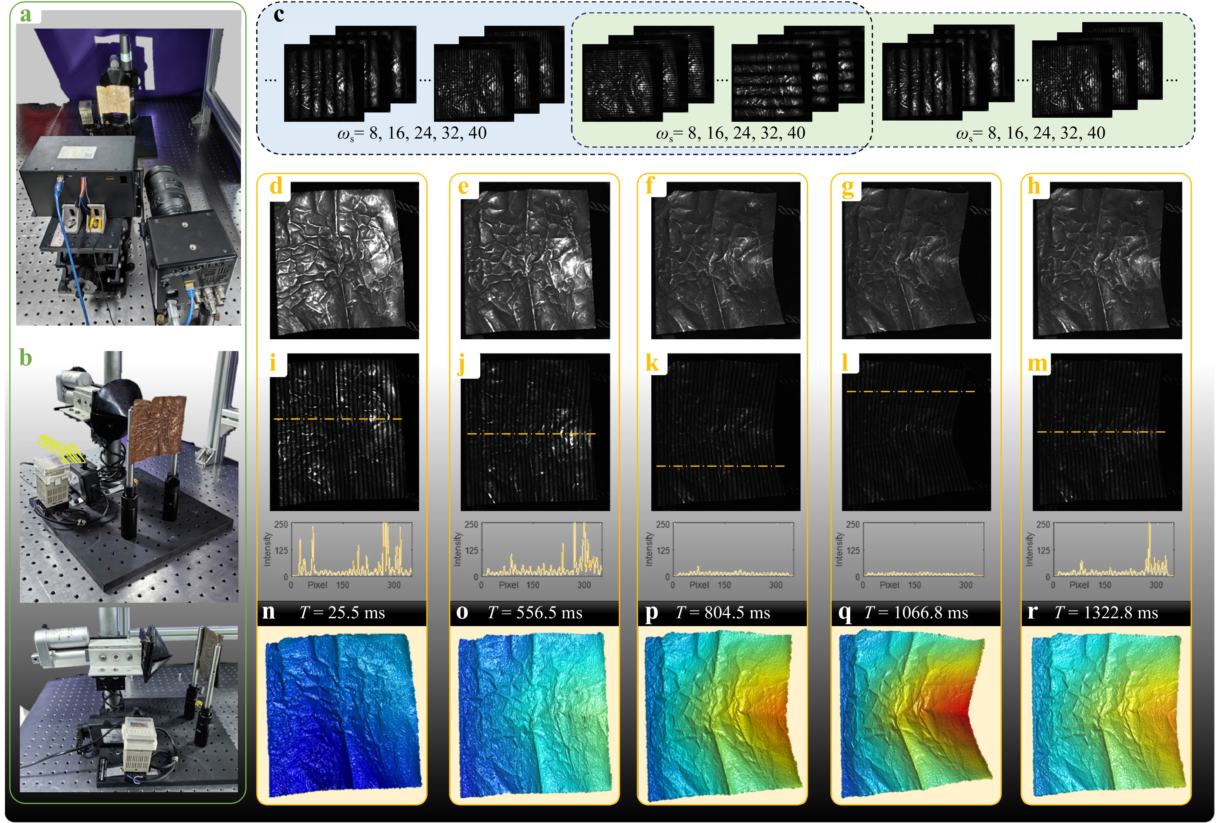
Fig. 3 Measurement of dynamic scenes with high dynamic range. a Experimental setup. b Measured dynamic squeezed scene. c Captured sequence patterns using time-overlapping projection. d−h Enhanced texture maps at five representative moments. i−m Captured deformed fringe patterns and their intensity distribution at five representative moments. n−r Corresponding reconstructed depth maps at five representative moments.
Enhanced texture maps at five representative moments on the deformed surface are shown in Fig. 3d−h. Because specular reflection occurs on the metal surface, the captured texture map and fringe pattern have a high-dynamic-range intensity distribution that changes with varying reflection angles, as shown in Fig. 3i−m, which is challenging for traditional FPP methods. The reconstructed depth results obtained using the proposed MS-PSI technique are shown in Fig. 3n−r, and the dynamic results are shown in Supplementary Video 1. This shows that the proposed method performs well in both the overexposed and low-light regions. The experimental results indicate that the proposed MS-PSI technique can achieve dynamic shape measurements with a high dynamic range.
-
In addition to complex reflection conditions, complex transmission conditions such as scattering media, including fog, smoke, and air turbulence, severely hamper the accurate 3D imaging of traditional SL methods. Therefore, we conducted a dynamic 3D imaging experiment through thin volumetric scattering media. Dry ice produced a dynamically changing fog in front of the unfolded hand. Traditional FPP and MS-PSI methods were used to reconstruct the 3D information of this challenging scene. Three-frequency 3-step phase-shifting patterns (ωl = 1, ωl = 4, ωh = 20, totally 9 patterns) are projected in the FPP method. In contrast, 5 groups of two-direction Fourier basis patterns (ωs = 8, 16, 24, 32, 40, a totally 30 patterns) were generated for horizontal and vertical Fourier slices in the MS-PSI method. A texture map and one of the fringe patterns at five representative moments are shown in Fig. 4a−e, respectively. This indicates that dynamic fog disturbs the fringe patterns, as the yellow dashed boxes indicate. The corresponding 3D imaging results obtained using FPP and MS-PSI are shown in Fig. 4f−g, respectively. The dynamic results are shown in Supplementary Video 2. This shows that reconstruction errors occur in the concentration area of the scattering media using FPP, whereas complete and stable 3D imaging results can be obtained using MS-PSI. This is because the MS-PSI method can extract the effective direct illumination component from the indirect scattering components. The experimental results demonstrate that the MS-PSI method can acquire stable and satisfactory 3D imaging results through thin volumetric scattering media. However, ballistic light weakens or disappears when measured through thick volumetric scattering media, and the direct illumination component cannot be detected for further 3D reconstruction.
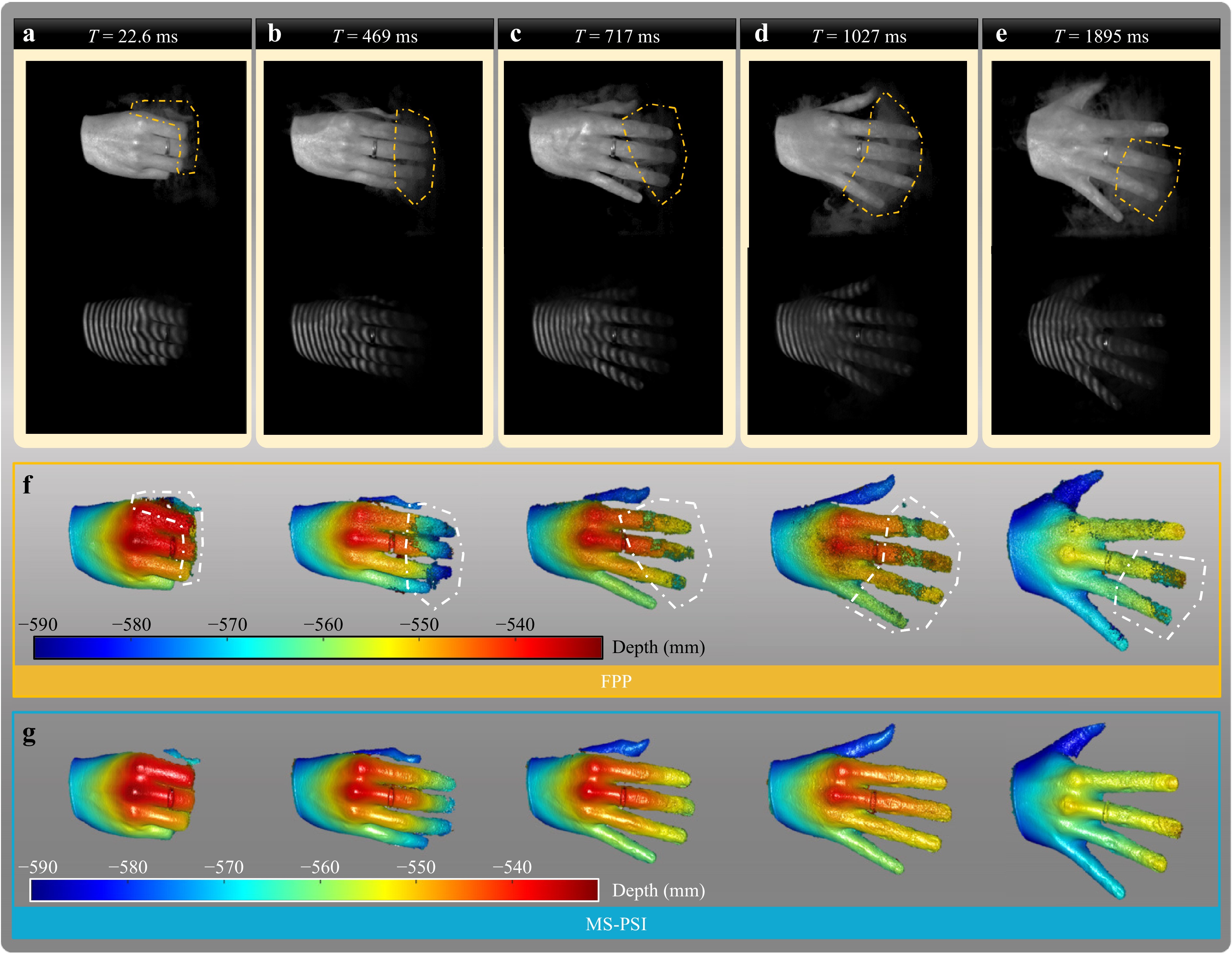
Fig. 4 Analysis of dynamic 3D imaging through thin volumetric scattering media. a−e Captured texture map and one of the fringe patterns at five representative moments. f 3D imaging results at corresponding moments using the traditional FPP. g 3D imaging results at corresponding moments using the proposed MS-PSI.
-
The MS-PSI method can separate the direct and indirect illumination components, and the indirect component was abandoned in 3D imaging in the aforementioned experiments. However, the indirect component can also be utilized in specific scenarios. In the final experiment, two-layer 3D imaging of a semitransparent surface and an object hidden behind it was achieved using the proposed method. A golf ball was moved behind a semitransparent frosted screen protector, as shown in Fig. 5a, b, and the captured fringe patterns at different moments are shown in Fig. 5c−f. It can be seen that the observed encoding information on a golf ball comprises the superposition of the fringe information reflected by the front and back layers. In contrast to the indirect component caused by interreflection and subsurface scattering, the collected reflection components from the front and back layers obey the point-to-point triangulation rule, as shown in Fig. 5g. Hence, the reconstructed and separated reflection components from the two layers fall on the epipolar line, as shown in Fig. 5h, i. These two reflection components can be used to realize the 3D imaging of the surface at the corresponding layer, as shown in Fig. 5j, k. Thus, a two-layer surface could be reconstructed simultaneously. The reconstructed 3D point cloud and triangular meshing results are shown in Fig. 5l−o and Fig. 5p−s. Experimental results demonstrate that the proposed method can simultaneously realize the 3D imaging of a semi-transparent surface and the hidden object behind it, which has not been reported in existing works to the best of our knowledge.
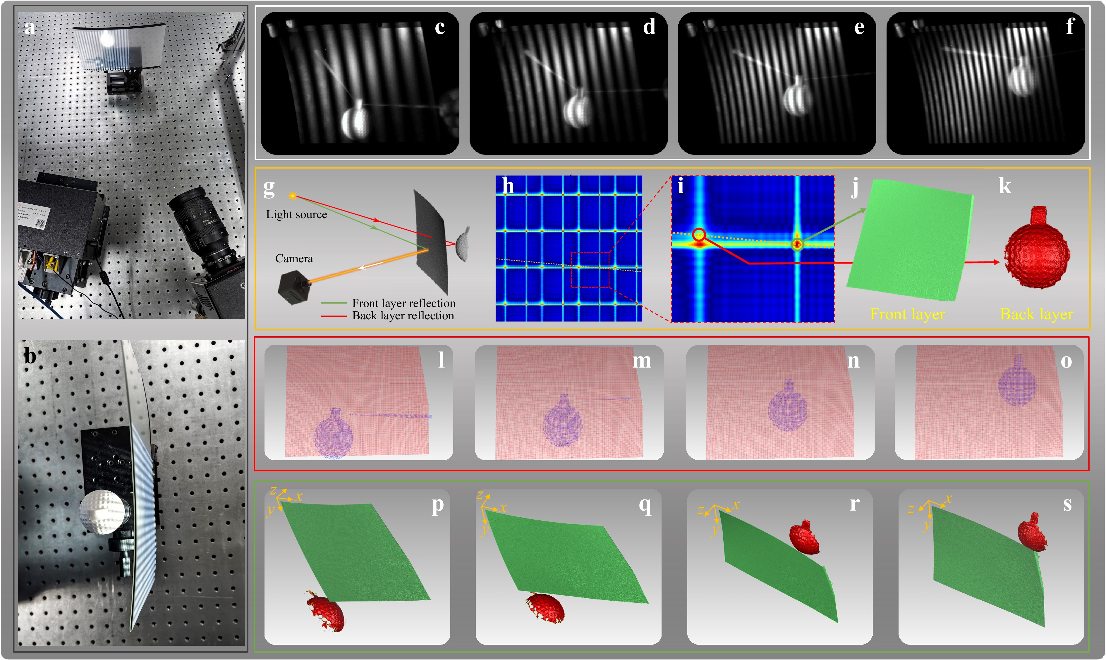
Fig. 5 Analysis of two-layer 3D imaging of a semitransparent surface and an object hidden behind it. a Experimental setup. b Fringe reflection on two-layer surfaces. c−f Captured fringe patterns at different moments. g Transmission process of illumination components on two-layer surfaces. h Reconstructed generalized light transparent coefficient. i Enlarged image of h. j−k 3D imaging results of the front layer and back layer. l−o Reconstructed 3D point cloud at four representative moments. p−s Triangle meshing results at four representative moments.
-
This study proposes a multi-scale parallel single-pixel imaging method for dynamic 3D shape reconstruction under complex reflection and transmission conditions. Fourier dual-slice projection with depth-constrained localization significantly decreases the number of required projected patterns from thousands to 30, making applying the PSI technique to dynamic measurements possible. By proving the position-invariant theorem, the presented multi-scale single-pixel imaging method can further improve the sampling efficiency and optimize the location accuracy with fixed pattern projection, as discussed in Supplementary Note S5. Combining this with the developed high-speed structured light system and a time-overlapping strategy, new 3D shape data of dynamic scenes with complex reflection or transmission conditions can be updated with only 15 new projected patterns. The experimental results demonstrate that the proposed method has the following abilities: 1) depth measurement for multi-type surfaces and high-dynamic-range scenes, 2) 3D imaging through thin volumetric scattering media, and 3) 3D imaging of two-layer surfaces.
Unlike the traditional FPP method, the proposed MS-PSI method does not obey the point-to-point triangulation rule and breaks existing PSI methods' regional light reception assumption. And it provides an efficient and general solution for separating complex illumination information, including subsurface scattering, inter-reflection, multi-layer superpositions, and thin volumetric scattering media, by recording the four-dimensional light transport coefficient. This paves the way for achieving dynamic 3D reconstruction under unusual reflection conditions, which has potential in challenging measurement tasks, such as crash test analysis with interreflection, biomechanical testing with subsurface scattering, and icing tests with mixed reflection conditions. In addition, the rapid illumination separation ability of MS-PSI offers new opportunities for 3D imaging under complex optical field transmission conditions, such as 3D imaging under strong light interference, 3D imaging through scattering media, and multi-layer 3D imaging. Furthermore, the developed technique can be applied to defect detection under extreme conditions, including online detection in additive manufacturing and optical element inspection with parasitic reflection. Thus, due to its point-to-plane imaging ability, MS-PSI can be extended to a wide range of science and engineering applications.
-
Our experimental system, shown in Fig. 3a, includes a DLP projector (DLP VisionFly 6500) with a resolution of 1920 × 1080 pixels and a high-speed camera (Photron FASTCAM Mini AX200). A zoom lens (Nikon AF-S 28–300 mm f/3.5-5.6G ED VR) was attached to the camera, the focal length was 35 mm, and the aperture was set to F8. In all experiments, the image refresh rate of the projector was set at 5000 Hz, and the camera was synchronized using a trigger signal from the projector. In the experiments on complex scenes with multi-type surfaces, as shown in Fig. 3, 512 × 512 projector pixels were used to generate the projected fringe patterns, and 1024 × 1024 pixels were used in the other experiments. The camera resolution was set to 1024 × 672 pixels in all the experiments. In addition, our experiments’ constrained depth between the two calibrated standard planes was 150 mm, and the measured objects should fall within this calibrated volume.
-
The light transport coefficient was reconstructed using the Fourier single-pixel imaging method, which is described in detail in Supplementary Note S1. A series of Fourier basis patterns were projected at different frequencies, and orientations were projected onto the tested surface to modulate the spectrum coefficient to varying positions of the light transport coefficient. Each pixel of the 2D camera was treated as a single-pixel detector, and the spectrum was reconstructed by collecting the spectrum information. After applying the inverse Fourier transform, the 2D light transport coefficient was reconstructed from a series of detected 1D intensity signals for each pixel.
-
After reconstructing the light-transport coefficient for each camera pixel, the direct illumination component must be distinguished and located. Because only direct illumination follows the point-to-point triangulation rule, this implies that direct illumination lies on the epipolar line, whereas global illumination does not. Hence, the epipolar line was first computed at46 for each camera pixel, and the depth-constrained data captured by the two defined standard planes were used to constrain the epipolar line into a line segment. And then, the distance threshold σ (σ = 5 pixel in this work) is adopted to construct a confidence region, as shown in the red bold line of Fig. 1e. The illumination component with a local maximum value that fell within this region was determined as the direct illumination component.
-
A triangular stereo model was adopted for system calibration. The projector was treated as an inverse camera and calibrated by projecting a series of vertical and horizontal fringes42. The camera was calibrated using the method described by Zhang’s method47. After calibrating the projector and camera, the stereo vision algorithm was used to reconstruct the 3D coordinates48. In addition, different reflection and transmission conditions cause different degrees of illumination energy diffusion in the generalized light transport coefficient, which affects the optimal parameter determination. Therefore, pre-calibration of the parameter selection should be performed during calibration to achieve the best performance. After calibration, the system can measure standard planes with different materials through smoke at different concentrations using various parameters. The mapping relationship between the scattering degree of the reflection and transmission media and the optimum system parameters s and c can be established and saved as calibration parameters for optimal parameter determination in the actual measurements.
-
This research was supported by the National Natural Science Foundation of China (62205226, 62075143), the National Postdoctoral Program for Innovative Talents of China (BX2021199), the General Financial Grant from the China Postdoctoral Science Foundation (2022M722290), the Key Science and Technology Research and Development Program of Jiangxi Province (20224AAC01011), and the Fundamental Research Funds for Central Universities (2022SCU12010).
Dynamic 3D shape reconstruction under complex reflection and transmission conditions using multi-scale parallel single-pixel imaging
- Light: Advanced Manufacturing 5, Article number: (2024)
- Received: 20 February 2024
- Revised: 02 June 2024
- Accepted: 09 June 2024 Published online: 25 July 2024
doi: https://doi.org/10.37188/lam.2024.034
Abstract: Depth measurement and three-dimensional (3D) imaging under complex reflection and transmission conditions are challenging and even impossible for traditional structured light techniques, owing to the precondition of point-to-point triangulation. Despite recent progress in addressing this problem, there is still no efficient and general solution. Herein, a Fourier dual-slice projection with depth-constrained localization is presented to separate and utilize different illumination and reflection components efficiently, which can significantly decrease the number of projection patterns in each sequence from thousands to fifteen. Subsequently, multi-scale parallel single-pixel imaging (MS-PSI) is proposed based on the established and proven position-invariant theorem, which breaks the local regional assumption and enables dynamic 3D reconstruction. Our methodology successfully unveils unseen-before capabilities such as (1) accurate depth measurement under interreflection and subsurface scattering conditions, (2) dynamic measurement of the time-varying high-dynamic-range scene and through thin volumetric scattering media at a rate of 333 frames per second; (3) two-layer 3D imaging of the semitransparent surface and the object hidden behind it. The experimental results confirm that the proposed method paves the way for dynamic 3D reconstruction under complex optical field reflection and transmission conditions, benefiting imaging and sensing applications in advanced manufacturing, autonomous driving, and biomedical imaging.
Research Summary
Beyond point-to-point triangulation: Dynamic 3D reconstruction under complex reflection and transmission conditions
Depth measurement and three-dimensional (3D) imaging under complex reflection and transmission conditions are challenging and even impossible for traditional structured light techniques, owing to the precondition of point-to-point triangulation. Qi-Can Zhang from China’s Sichuan University and colleagues now report a multi-scale parallel single-pixel imaging method that efficiently separates and utilizes different illumination and reflection components for dynamic depth measurement on multi-type surfaces and 3D imaging through complex transmission media, such as volumetric scattering media and semitransparent surface. The team demonstrated its effectiveness and results are promising for 3D imaging and sensing applications in advanced manufacturing, autonomous driving, and biomedical imaging.
Rights and permissions
Open Access This article is licensed under a Creative Commons Attribution 4.0 International License, which permits use, sharing, adaptation, distribution and reproduction in any medium or format, as long as you give appropriate credit to the original author(s) and the source, provide a link to the Creative Commons license, and indicate if changes were made. The images or other third party material in this article are included in the article′s Creative Commons license, unless indicated otherwise in a credit line to the material. If material is not included in the article′s Creative Commons license and your intended use is not permitted by statutory regulation or exceeds the permitted use, you will need to obtain permission directly from the copyright holder. To view a copy of this license, visit http://creativecommons.org/licenses/by/4.0/.

 DownLoad: