


-
Minimally invasive endoscopy is highly relevant for biophotonic research for instance in neuroscience1 and for minimally invasive medical applications for example in neurosurgery2, 3 or inner ear surgery4.
Normally, distal optics are used for fiber based endoscopy for (de-) magnification of the 2D image plane on the distal fiber facet5, 6. In the last decade multiple approaches based on correcting the inherent distortion of the light propagation through waveguides7−10 or core-wise scanning of a multicore fiber11, 12 have been demonstrated showing significant advances towards ultra-thin lensless endoscopes. These systems work without optics at the distal end and are also named lensless endoscopes. On the one hand data driven approaches rely on inverting the complex light distortion during propagation based on learned examples in post processing13−19. On the other hand, physic based approaches rely on measuring the optical transfer function (OTF), most commonly via digital holography20 and using spatial light modulator (SLM) for digital optical phase conjugation (DOPC), subsequently21, 22. The fiber is illuminated with the conjugate of the wavefront distortion, which results in an undistorted wave at the fiber output. Multicore fibers (MCF) and multimode fibers (MMF) have been used. While MMFs are thinner and offer higher information density, MCFs exhibit only low order OTF changes upon bending and have less complex propagation characteristics benefiting from a strong memory effect7, 23, 24. Thus, variations of the input wave directly translates to the output and fast 3D scanning using adaptive optics on the proximal side is enabled25. Additionally, simplified calibration procedures become available26, 27.
Special MCF designs have been proposed which offer an increased field of view, higher photon efficiency and bending independent OTF28−31. This enables distortion compensation via static single or multilayered holograms for compact and robust designs with reduced complexity32, 33. Multiple minimally invasive applications have been enabled based on physical correction of the OTF in fibers such as label free Coherent anti-Stokes Raman scattering spectroscopy (CARS) endomicroscopy34, endoscopic 3D printing35, 2-photon excited fluorescence microscopy36, laser ablation37, photoacoustic endomicroscopy38, 39 or single cell tomography using optical tweezers40.
A major drawback of the proposed approaches compared to the state-of-the-art broadband lens-based imaging41 is their narrow spectral range. Since, the wavefront distortion results from dispersion, the phase distortion is wavelength dependent. Thus, DOPC is only able to correct for a narrow spectral range around the operating wavelength. In principle, multispectral correction is feasible via Time Division Multiplexing (TDM), Space Division Multiplexing (SDM) or similar and was shown for multispectral focusing in scattering media such as tissue or MMF42−45. These methods come with the cost of increased system complexity or reduced temporal resolution. Most significantly, TDM impedes the otherwise advantageous use of static 3D printed passive holograms. Furthermore, it prohibits the simultaneous correction of multiple wavelengths for instance for optogenetics46 or label-free biomedical imaging like confocal fluorescence imaging or CARS endomicroscopy47.
The underlying problem for lensless fiber endoscopy using MCFs is the scattering of effective refractive index $ n_{eff} $, due to scattering in material properties and fiber geometry. This results in a scattering of the optical path length $ l_{opt} = n_{eff} \cdot l $ which is proportional with the geometric fiber length $ l $. The phase at the fiber output results to $ \phi = 2\pi \cdot \text{mod}( {n_{eff} \cdot l}/ {\lambda},1) $. Considering a perfectly phase (but not length) corrected fiber at the design wavelength $ \lambda_D $, a wavelength dependent phase distortion $ \phi (\Delta\lambda)=2\pi \cdot n_{eff} \cdot l \cdot ({\Delta \lambda}/ {\lambda_D^2}) $ results, where $ \Delta \lambda = \lambda-\lambda_D $. This means, the phase compensation deteriorates with increasing wavelength shifts $ \Delta \lambda $ from the design wavelength, with increasing scattering of the effective refractive index and with increasing fiber length. The issue is sketched out in Fig. 1. Fig. 1a shows the field if a MCF is illuminated with a coherent wave of wavelength $ \lambda_D $. Dispersion induced phase distortion results in speckles in the far field. Fig. 1b shows the field if the MCF is phase corrected. The individual beams interfere constructively to form a focus. Fig. 1c shows the same phase corrected MCF again, but illuminated with a broadband wavelet centered around $ \lambda_D $, with the bandwidth $ \Delta \nu $. Only if the optical path length difference in the fiber is below the coherence length $ L_c=({2 ln 2}/{\pi})({\lambda_D^2}/{n_{eff} )\Delta \nu} $ or pulse length respectively constructive interference occurs, see Fig. 1d.
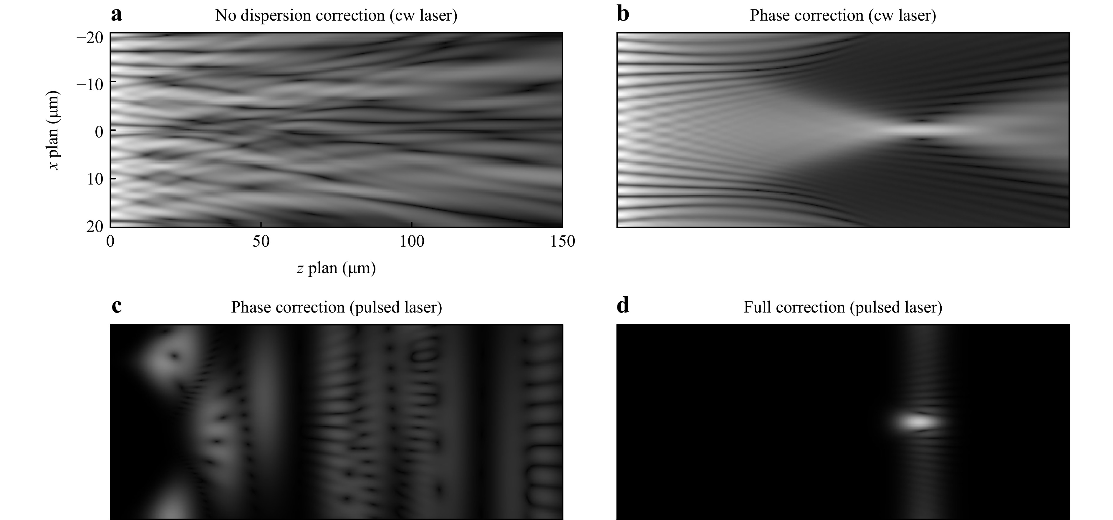
Fig. 1 Simulation: A converging beam couples into the proximal fiber facet. A Snapshot of the resulting intensity at the distal fiber end is shown for different light sources and different corrections. Top row: A narrow band continuous wave (cw) laser source is used. a Due to intercore dispersion, the phase is scrambled and a speckle pattern results without a focus. b For a narrow linewidth source phase correction within a maximum stroke of $ 2\pi $ enables focusing. Bottom row: A broadband cw or ultra-short pulsed light source is used. c With phase correction with a maximum stroke of $ 2\pi $, dispersion impedes focusing and needs to be reduced below the coherence length or pulse length, d to form a focus.
In order to gauge the issue for real fibers, $ \sigma_n $ was measured for a commercial MCF (Sumita HDIG, 10,000 cores, length 1 m) using a low coherence interferometer, see Fig. 2a. A fiber coupled super luminescent diode (SLED, $ \lambda = \text{650 nm} $, $ \Delta \lambda = \text{6 nm} $, Exalos, EXS210033-04) was used. A 50:50 fiber based y-coupler (Y 50:50, Thorlabs TW670R5A1) splits the light into the object and reference beam, respectively. The MCF was imaged onto a camera using a 20x microscope objective (MO1) and a tube lens (L2). Polarization filters (PF) were employed to adjust the relative amplitudes and to guarantee equal polarization of reference and object beam. The optical path length was measured by scanning the reference mirror M1 and a core wise evaluation of the interference fringe contrast in an off-axis hologram. Bending induced dispersion as well as aberrations of the reference beam were removed by lateral high pass filtering of the measured dispersion map. Fig. 2b shows the distribution of the measured deviation of the refractive index $ \Delta n $. A standard deviation of $ \sigma_n \approx 10^{-4} $ results, meaning a 1 m long fiber exhibits a standard deviation of the optical path length of around 100 µm. This limits the possible fiber length for non-linear endomicroscopy using ultra short laser pulses due to pulse broadening, for speckle-free broadband light sources, and correction of broadband fluorescenct light, for instance. This can be circumvented with advanced schemes with multiple SLMs for spatio-temporal beam shaping, increasing system complexity even further48.
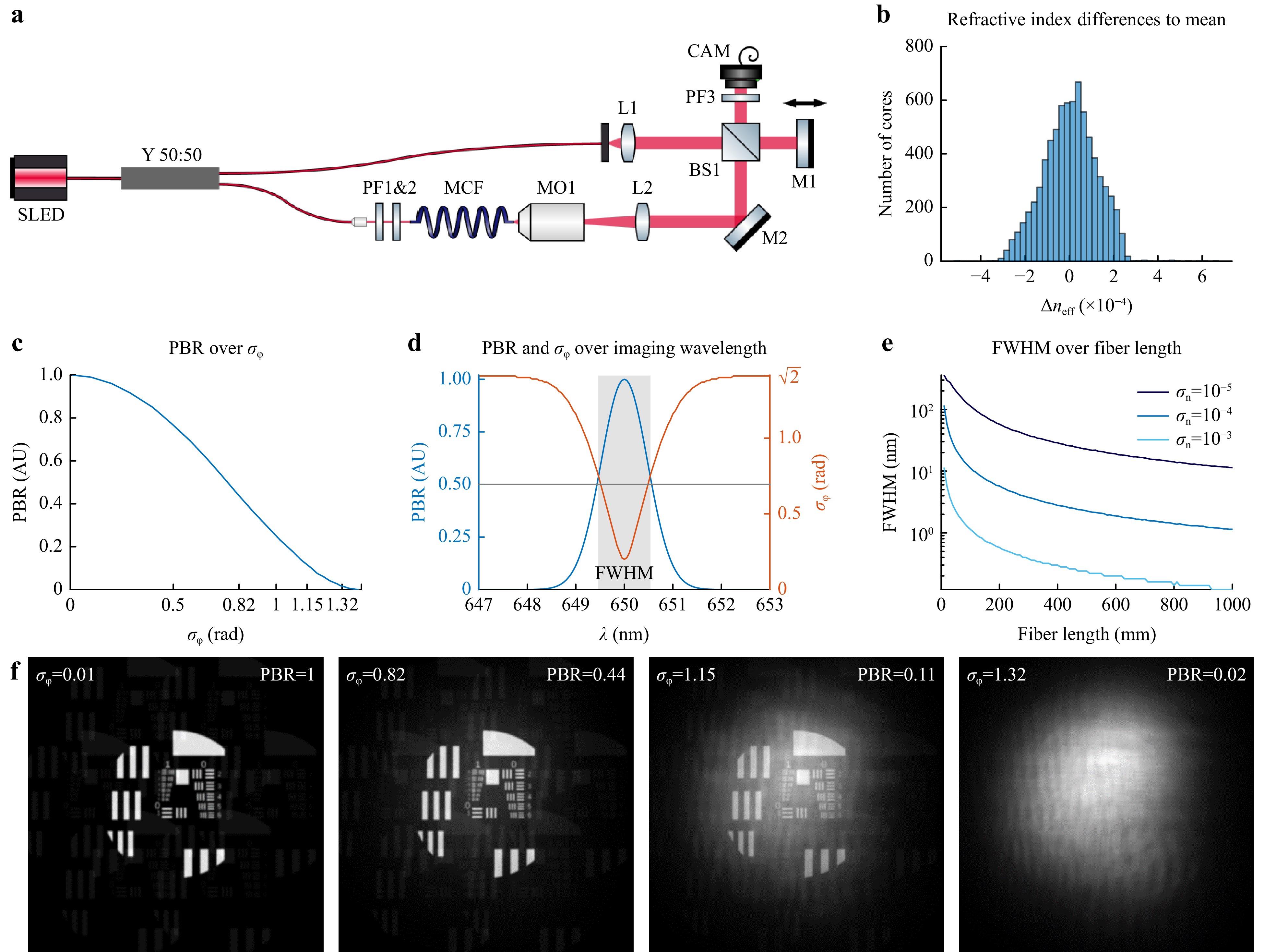
Fig. 2 a White light interferometer to measure the intercore dispersion in a fiber bundle. b Histogram of measured refractive index deviations of the commercial MCF. The standard deviation results to $ \sigma_n = 10^{-4} $. c Simulation: Focus quality measured in PBR in dependence of phase noise $ \sigma_\phi $. d Simulation: Spectrally resolved PBR and $ \sigma_\phi $ for the fiber with perfect phase correction for 650 nm. e Simulation: FWHM for different fiber lengths calculated for different standard deviations of the refractive index. f Simulated imaging with lensless endoscope using MCF with different corrections.
Based on the effective refractive index scattering the wavelength depended phase distortion can be calculated. The phase distortion is described by the standard deviation of the emitted phase which is $ \sigma_\phi = 0 $ for a perfectly corrected MCF, whereas a fully random MCF with equally distributed phase would result to $ \sigma_\phi = \sqrt{2} $. The phase deviation limits the achievable imaging contrast, which is characterized by the peak-to-(mean)background ratio (PBR)49. Fig. 2c shows the dependency $ \text{PBR}(\sigma_\phi) $. Based on the measured $ \Delta n $ the resulting PBR was simulated for varying wavelengths assuming correction for $ \lambda_c = \text{650 nm} $. The measurement uncertainty was estimated in with $ \sigma_{\phi_{meas}} \approx 0.2 $ limiting the minimal phase distortion. We assumed wavelength independence of the refractive index, meaning no chromatic dispersion. An increased wavelength shift $ \Delta\lambda $ increases the phase noise $ \sigma_\phi $, thus decreasing the PBR, see Fig. 2d. The width of the graph indicates the spectral range of the phase correction. This can be evaluated with the full width at half maximum (FWHM). The FWHM of 1.1 nm demonstrates that for the given fiber $ \sigma_{l,opt} $ only narrow band imaging using DOPC is feasible. The spectral range can be increased by shortening the fiber or decreasing $ \Delta n $ as shown in Fig. 2e. In order to illustrate the influence of PBR on the resulting image, lensless imaging through a MCF with varying $ \sigma_\phi $ was simulated using Fourier-optics, see Fig. 2f. As expected, image quality decreases with increasing phase deviation. However, Fig 2f also shows, that imaging is feasible with non perfect phase correction.
Since, the phase stroke in SLM is wavelength dependent and can exceed 2π, multi spectral holograms with wavelength dependent phase patterns for partial phase correction can be generated50. Thus, multispectral imaging is feasible, in principle. In order to test this assumption a numerical simulation was performed using the single-shot imaging method proposed by Tsvirkun et al.51, but any DOPC-based method could be used. The object is imaged with a microscope objective and tube lens on a camera. The phase-compensated MCF is put in between the object and the microscope objective, the objective focuses through the MCF. As the fiber facet is in between the object and Fourier plane the spatial resolution is no longer limited to the MCFs core count.
A fiber with $ l=\text{0.1 m} $, $ \sigma_n \approx 10^{-4} $ and 10,000 cores was simulated by generating 10,000 Gaussian distributed core lengths. The resulting phase distortion was calculated for 3 wavelengths $ \lambda_1=\text{450 nm} $; $ \lambda_2=\text{520 nm} $; $ \lambda_3=\text{638 nm} $, assuming no chromatic dispersion. A calibration measurement of this phase distortion was simulated to take measurement noise into account by adding Gaussian distributed phase values with $ \sigma_{meas} = 0.2 $. An SLM based DOPC was simulated. A linear dependency between SLM gray value and optical path length retardation was assumed. This means the phase retardation is wavelength dependent. The maximum stroke of the SLM was used as a variable within the simulation in order to estimate its influence.
Three different approaches for multispectral imaging are applied and compared:
• Time Division Multiplexing (TDM): An individual hologram per color is calculated. A sequential RGB source is used. The SLM is synchronized to the source, displaying the corresponding holograms. As an advantage, images are taken for every color and combined afterwards to one RGB image. Thus, an optimal compensation is enabled independent of the wavelength, see Fig. 3a (gray). As a disadvantage, TDM requires dynamic, time depended holograms. Thus, imaging modalities requiring simultaneous multispectral illumination or detection such as confocal fluorescence microscopy are not feasible. Additionally, robust and cheap static phasemask 3D printing is inhibited. Furthermore, the imaging speed is limited by the switching time of the SLM and the number of color channels.
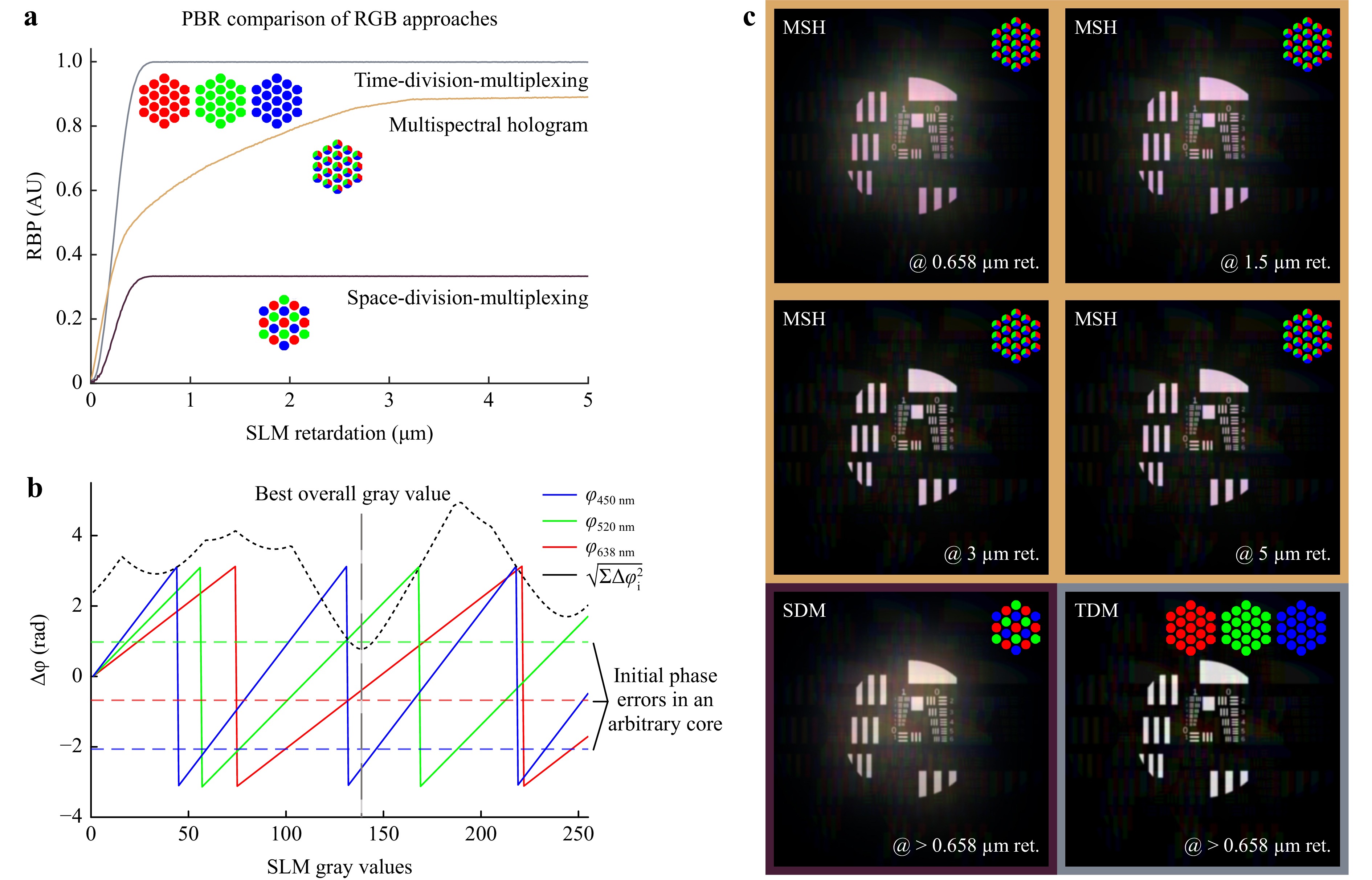
Fig. 3 a Achievable PBR in dependency of SLM retardation for time division multiplex, multispectral holograms and space division holograms. The working principles are illustrated under each curve. b Preliminary measured phase shifts for the different gray values of the SLM for different wavelengths (here the dependency is linearized, solid lines in red, green, and blue). Using this the gray value for each fiber core is calculated separately, it is the minimum of the MSE (black dotted line). The minimum of the MSE corrects all colors partially: a multispectral hologram. c The simulated images compare the achievable image qualities using different max. retardations with an 8 bit SLM and an LED (MSH: Multispectral Hologram; SDM: Space-Division-Multiplexing; TDM: Time-Division-Multiplexing).
• Space Division Multiplexing (SDM): Each core is assigned to one of the colors. It is ensured that each color occurs with equal frequency and is evenly distributed on the fiber facet. The cores are then wavelength filtered according to their assigned color in a Bayer-pattern like filter. One static hologram is calculated where each core is compensated for their color. As an advantage, a static hologram can be employed. Thus, single-shot imaging becomes feasible if a multispectral lightsource is used. Additionally, imaging modalities requiring simultaneous multispectral illumination or detection such as confocal fluorescence microscopy can be realized. As a disadvantage, this limits the amount of available fiber cores $ N $ per wavelength. Consequently, it reduces the achievable PBR which scales linearly with $ PBR \approx {{\text π} N}/{4} $49. Thus, lower contrast images result.
• multispectral Hologram (MSH): One static hologram is calculated compensating all colors using all cores at the same time: For each core the merit function $ \sqrt{\sum_1^3\Delta\phi_i(S)^2} $ is minimized. Where $ S $ is the SLM gray value. The optimal gray value results in phase correction, that is descent for all wavelengths on average, see Fig. 3b. As an advantage, a static hologram can be employed and all fibers can be used for all wavelengths. Thus, single-shot imaging becomes feasible if a multispectral lightsource is used. Additionally, imaging modalities requiring simultaneous multispectral illumination or detection such as confocal fluorescence microscopy can be realized. As a disadvantage, the fibers are not corrected perfectly, reducing PBR. However, it is obvious in Fig. 3a (yellow), that the image contrast increases with increasing stroke $ \Delta s $. For Δs = 1.1 µm it doubles the achievable PBR compared to SDM and at Δs = 1.7 µm 75% of maximum achievable PBR of TDM are reached.
The simulation results are summarized in Table 1. The frame rate (Frames-Per-Second, FPS) and the PBR as metric for the contrast are compared for the different methods normalized on the results of TDM $ FPS_{TDM} $ and $ PBR_{TDM} $. TDM achieves the highest contrast but with the lowest frame rate. MSH is three-times faster than TDM with 87% of its contrast at 3 µm maximum retardation.
TDM@>0.658 μm SDM@>0.658 μm MSH@0.658 μm MSH@1.5 μm MSH@3 μm $ {FPS}/{FPS_{TDM}} $ 1 3 3 3 3 $ {PBR}/{PBR_{TDM}} $ 1 0.32 0.57 0.72 0.87 Table 1. Comparison of the simulation results for different maximal retardations.
For experimental validation, a commercial MCF (Sumita HDIG, 10,000 cores, length 0.1 m) was calibrated multispectrally using a Mach-Zehnder interferometer, see Fig. 4a. An RGB-laser was used (450 nm, 520 nm, 638 nm, FISBA READYBeam). The reference beam path (Fig. 4, yellow) uses a mirror on a stage to accommodate the fiber length. The object beam (Fig. 4, blue) passes the MCF. A x20 microscope objective and a tube lens image the distal fiber facet onto the SLM (Holoeye PLUTO-NIR-011, max. retardation 1.1 µm). The SLM is imaged via a 4f-system through a polarization filter on CAM1 (iDS UI-3482). The reference beam path is tilted in regards to the object beam for off-axis holography. Initially without a fiber, one calibration measurement per wavelength was taken to generate look-up-tables for the relationship “phase retardation – SLM gray value”. After inserting the MCF, three phase measurements were taken sequentially for each wavelength to obtain the phase error for each core and for each color. Fig. 4b shows the setup for testing and comparing the 3 different imaging schemes. A USAF-testchart is used as a reference object for imaging. The calibration laser is replaced with an RGB LED for illumination in transmission, see Fig. 4b. Using incoherent light is feasible due to the reduced fiber length as shown in Fig. 2. The testchart is placed 700 µm in front of the proximal fiber facet. From the R, G, and B calibration holograms the three correction schemes are calculated and displayed on the SLM. Images are recorded with CAM2 (iDS UI-3482) and displayed in Fig. 4c.
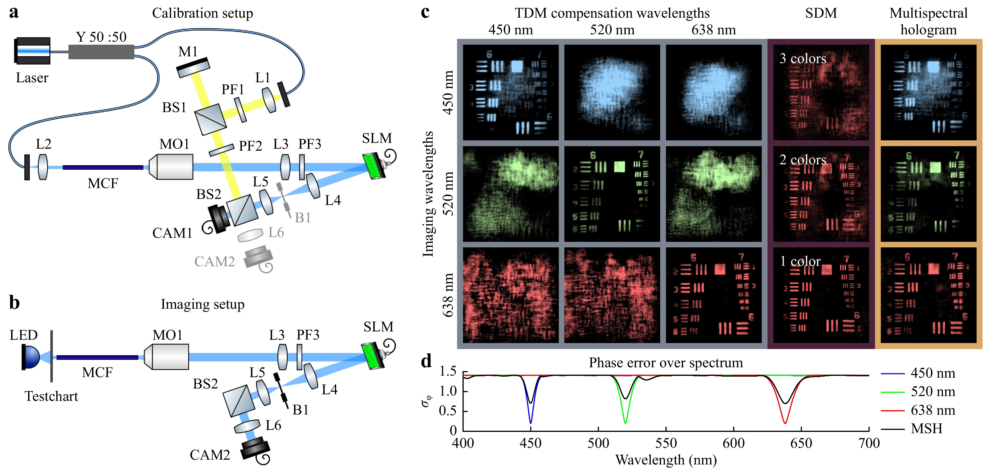
Fig. 4 a Setup for calibration: Off-axis Mach-Zehnder interferometer is used for phase measurement. The reference beam is yellow, the object beam blue. b Setup for imaging: The additional lens L6 images CAM2 in the far field of the MCF. c Acquired images with sequential illumination & receiving beam forming using an SLM with a maximal retardation of 1.1 µm. The multispectral holograms allows imaging with all three wavelengths with a single hologram. d Simulation: Comparison between three single spectral corrections at R, G, and B and a multi spectral correction.
HTML
-
The left cluster of 3x3 depicts the recorded image for each wavelength in dependence of the hologram used for correction. The holograms enable high contrast images, but only for their designated wavelengths. For different wavelengths the object becomes indistinguishable. The simulated graph underneath illustrates the wavelength dependency of the phase error of each hologram.
-
The effect of using a reduced number of fiber cores was implemented by angular filtering on the SLM. This means light from the filtered fiber cores was absorbed in the beam block B1. 3,300, 5,000, and all 10,000 fiber cores were chosen randomly to simulate SDM with 3, 2 colors, and 1 color respectably. Here, the red color channel is shown. It can be seen that the contrast reduced drastically with decreasing core number.
-
Single-shot RGB imaging is enabled. As predicted by the simulation, the contrast is lower compared to TDM, but exceeds SDM significantly. Here the stroke was restricted to 1.1 µm. The contrast could be improved further, using a higher stroke SLM.
Lensless MCF endoscopy is promising for minimally invasive applications. The inherent narrow band principle limits applications however. We compared different approaches to enable multispectral lensless MCF endoscopy. Time division multiplexing maximizes the achievable imaging contrast, at the cost of a reduced frame rate and it does not enable modalities requiring simultaneous multispectral correction. Space Division Multiplexing is single-shot but greatly reduces imaging contrast. However, multispectral static holograms enable lensless single-shot multispectral endoscopy with a slightly diminished contrast. We demonstrated RGB imaging using a commercial SLM. However, further modalities relying on simultaneous multispectral phase correction can be enabled by static holograms as well. For instance CARS or confocal fluorescence endomicroscopy are enabled and can enhance diagnostic value, for instance in tissue differentiation. Additionally, employing a static multispectral correction enables using 3D printed holograms. These can be applied directly onto the fiber facet using two-photon polymerization in order decrease system complexity and price, and to increase robustness. To further improve the image quality a broadband dispersion correction needs to be implemented. Using metasurfaces or multiple DOEs is a promising direction52, 48. For translation to the clinic, it is necessary to show that the multispectral approach also works with static DOEs, due to the required low maintenance and low failure rates. Many procedures would benefit from the endoscope's small form-factor, like neurosurgical or inner-ear surgeries.
Time division multiplexing
Space division multiplexing
Multispectral hologram
-
Funding by Deutsche Forschungsgesellschaft (DFG Cz55/47-1), by the German Federation of Industrial Research Associations (AiF 21802 BG), the European Regional Development Fund (ERDF), and the Development Bank of Saxony (SAB) is gratefully acknowledged. We want to thank Elisabeth Berkholz, Leon Stiffel and Dr. Martin Kroll for their valuable support.

 DownLoad: