


-
The interaction between ultrafast lasers and materials gives rise to a range of intriguing nonlinear transient phenomena that are crucial to cutting-edge scientific research fields, such as attosecond science1,2, ultrafast laser filamentation3,4, and ultrafast laser fabrication5,6. The interaction of ultrafast lasers with solid matter often involves numerous physical processes, including changes in the material properties and surface/internal structuring. For instance, ultrafast laser ablation involves a series of physical processes: electronic system excitation and lattice energy transfer (resulting in heating and melting), followed by material removal and re-solidification5−7. Recently, double-pulse ultrafast laser techniques have been explored to achieve a higher degree of control over the structuring process8−13. For example, studies have shown the formation of hexagonal9, triangular10, and square patterns11, as well as more complex labyrinthine and chaotic symmetries12,13. However, understanding the nonlinear mechanisms governing pattern selection remains challenging. To fully capture the evolution of these dynamic processes and establish precise physical models, accurate measurements of both material properties and structure formation with high temporal and spatial resolutions are essential in the transient state. However, many existing spatiotemporal imaging techniques often yield only partial information and fail to capture the complete dynamics of material properties and structural changes. Consequently, current models tend to be predominantly qualitative and lack the precision and reliability required for accurate predictions.
Currently, the primary method for studying laser ablation is pump-probe microscopy, which combines ultrafast time resolution with microscopic spatial resolution to capture images of reflected surfaces at different time intervals after irradiation14−20. This technique enables the determination of time scales for the ionisation, ablation, and solidification processes under ultrafast laser irradiation14−17. It has also been employed to study the rapid evolution of femtosecond laser-induced periodic surface structures (LIPSS) in various metallic materials, offering a temporal resolution of 0.6 ps and a spatial resolution of 345 nm18−20. Alternative approaches, such as those utilising hyperspectral cameras, have been developed to enable single-pulse capability, albeit at the expense of temporal resolution21,22. Despite these advancements, most techniques are limited in their ability to only measure the reflectivity map for analysis, thus constraining their ability to fully capture transient three-dimensional structural information.
Recent studies, such as monitoring the ultrafast evolution of micrograting generation through diffraction efficiency measurements23 and capturing 3D plasma evolution via reflection and transmission imaging24, provide supplementary information for reflectivity imaging, but face challenges when handling complex objects. In 2022, three-dimensional wide-field single-probe structured light microscopy (SPSLM) based on Fourier transform profilometry (FTP) was introduced in our previous study25, enabling rapid and high-resolution mapping of surface topography. However, reflectivity information was lost. Additionally, the spatial resolution of 457 nm was constrained by oblique incidence in the triangulation configuration, and the reconstruction was prone to errors induced by the shadow effect26,27.
To address these limitations, this paper presents a dual-modal spatiotemporal microscopy approach that integrates a pump-probe technique and an interferometric imaging system, allowing for the simultaneous acquisition of ultrafast changes in two-dimensional reflectivity and three-dimensional topography. The system achieves highly accurate surface profile measurements with a remarkable lateral spatial resolution of 236 nm and a temporal resolution of 256 fs, reducing the errors associated with the shadow effect in traditional triangulation setups. Through the application of this system, we investigated the intricate ultrafast dynamics of double-pulse laser-induced surface patterns involved in the generation and removal of LIPSS on silicon surfaces induced by double femtosecond pulses of different polarisations. Our findings reveal that although melting occurs before ablation, the formation of LIPSS is primarily driven by modulated ablation resulting from modulated energy deposition during laser-matter interaction, rather than the hydrodynamic movement of the molten material. Furthermore, the melting process that occurs before ablation weakens and erases the existing structures, enhancing the newly formed LIPSS patterns. Our study highlights the sensitivity of the reflectivity imaging mode to changes in optical properties, whereas the topography imaging mode offers a more accurate representation of structural changes. The combination of these two complementary spatiotemporal imaging modalities provides more comprehensive insight into the fundamental physics of laser fabrication processes, offering significant potential for achieving more precise control in laser manufacturing.
-
The system configuration shown in Fig. 1 comprises a cross-polarised pulse pair used to fabricate the LIPSS, along with a dual-modal spatiotemporal imaging module designed to record the evolution of LIPSS formation. The light source was an amplified Ti: sapphire laser system (Coherent, Legend Elite HE) with a central wavelength of 800 nm, pulse duration of 120 fs, and pulse energy of 6 mJ. The output beam was frequency-doubled using a β-barium borate (BBO) crystal. A dichroic mirror was used to separate the fundamental and frequency-doubled beams. The fundamental beam, with a central wavelength of 800 nm, served as the pump beam and underwent secondary modulation before being directed onto the sample surface for LIPSS generation. The frequency-doubled beam with a central wavelength of 400 nm served as the probe beam and was dedicated to a dual-modal ultrafast imaging setup.
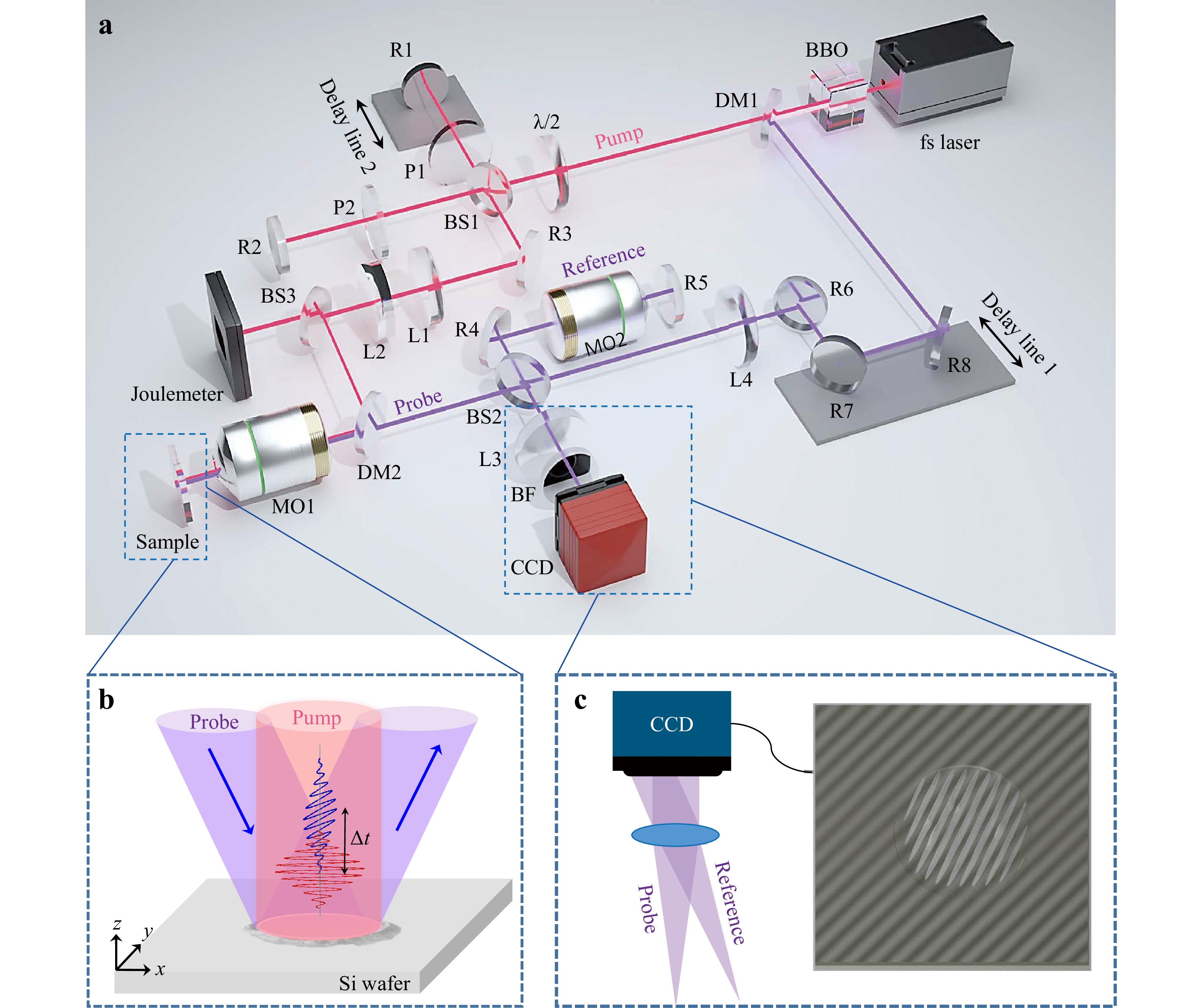
Fig. 1 Schematic of our dual-modal spatiotemporal imaging system. a Optical layout of the system. Red indicates the pump light (at 800 nm), while violet represents the probe light (at 400 nm). Illustration of pump and probe pulses on the silicon wafer is shown in b. Interference of the probe and reference pulses on CCD is shown in c. Abbreviations: BBO, barium boron oxide; DM1-DM2, dichroic mirrors; L1−L4, lenses; R1−R8, reflectors; BS1−BS3, beam splitters; P1−P2, polariser; BF, bandpass filter; CCD, charge-coupled device; MO1−MO2, microscope objectives (Olympus MPLFN100xBD, 100×, NA = 0.9).
The pump light was split into two pulses that were modulated to be cross-polarised and then combined to form a cross-polarised pulse pair in the Michelson interferometer setup. Two adjustable linear polarisers (P1 and P2) enabled independent manipulation of the polarisation within each arm. The dual-modal probe module was established using another Michelson interferometer, in which one arm directed light onto the fabricated LIPSS surface at a near-perpendicular angle to encode information in the reflection. The phase of the reflection was modulated by the height difference resulting from the LIPSS. To compensate for aberrations, the reference beam in the other arm passes through an objective lens of the same type but is reflected by a flat surface. The two beams were collimated using a tube lens and interfered with the plane of the charge-coupled device (CCD). Subsequently, by analysing the captured interference pattern using Fourier transform, both the time-resolved reflectivity and 3D topography can be obtained to interpret the ultrafast dynamics of laser ablation.
Here, the probe beam, which is reflected from the sample surface with a delay $ {\mathit{t}}_{\mathit{d}} $ relative to the pump light and incident onto the CCD plane with an angle $ \left({\mathit{\alpha }}_{1},{\mathit{\beta }}_{1},{\mathit{\gamma }}_{1}\right) $, can be described as follows:
$$ {\mathop {\;{\rm{E}}_{1}\;} \limits^ \rightharpoonup(\mathop {\rm{r}} \limits^ \rightharpoonup,{\mathit{t}}_{\mathit{d}})={{A}}_{1}\left({x},{y},{{t}}_{{d}}\right){\cos}[{\omega }{t}-\mathop{{\rm{k}}_{1}}\limits^ \rightharpoonup \cdot \mathop{\rm{r}}\limits^ \rightharpoonup +{b}\cdot {h}\left({x},{y},{{t}}_{{d}}\right)+{{\varphi }}_{1}] }$$ (1) where $ \mathit{h}\left(\mathit{x},\mathit{y},{\mathit{t}}_{\mathit{d}}\right) $ is the ablated height variation at the delay time $ {\mathit{t}}_{\mathit{d}} $, $ \mathit{b} $ is a proportional coefficient, $ {\mathit{A}}_{1}\left(\mathit{x},\mathit{y},{\mathit{t}}_{\mathit{d}}\right) $ is the scattering intensity of the ablated structure, $ \mathit{\omega } $ is frequency, $ \mathop {\;{\rm{k}}_{1}\;} \limits^ \rightharpoonup=\left({k}{\cos}{{\alpha }}_{1},{k}{\cos}{{\beta }}_{1},{k}{\cos}{{\gamma }}_{1}\right) $ is the wavevector of the probe beam, $ \mathit{k} $ denotes the wave number, and $ {{\varphi }}_{1} $ is the initial phase. For simplicity, the frequency $ \mathit{\omega } $ of the femtosecond optical pulse in the formula is approximated by the central frequency.
Similarly, the reference beam, which reflects from a flat surface and is incident onto the CCD plane with an angle $ \left({\mathit{\alpha }}_{2},{\mathit{\beta }}_{2},{\mathit{\gamma }}_{2}\right) $, can be described as follows:
$$ \mathop {\;{\rm{E}}_{2}\;} \limits^ \rightharpoonup(\mathop {\;{\rm{r}}\;} \limits^ \rightharpoonup,{{t}}_{{d}})={{A}}_{2}{\cos}[{\omega }{t}-\mathop {\;{\rm{k}}_{2}\;} \limits^ \rightharpoonup\cdot \mathop {\;{\rm{r}}\;} \limits^ \rightharpoonup+{{\varphi }}_{2}] $$ (2) with $ {{A}}_{2} $ being the reflected intensity, $ \mathop {\;{\rm{k}}_{2}\;} \limits^ \rightharpoonup=({k}{\cos}{{\alpha }}_{2}, {k}{\cos}{{\beta }}_{2},{k}{\cos}{{\gamma }}_{2} )$ the wavevector of the reference beam, and $ {{\varphi }}_{2} $ the initial phase.
The interference pattern of the two beams is then expressed as:
$$ \begin{split}{I}&\left({x},{y},{{t}}_{{d}}\right)={\langle{\mathop {\;{\rm{E}}_{1}\;} \limits^ \rightharpoonup (\mathop {\;{\rm{r}}\;} \limits^ \rightharpoonup,{{t}}_{{d}})+\mathop {\;{\rm{E}}_{2}\;} \limits^ \rightharpoonup(\mathop {\;{\rm{r}}\;} \limits^ \rightharpoonup,{{t}}_{{d}})}\rangle^{2}}={{A}}_{1}^{2}\left({x},{y},{{t}}_{{d}}\right)+{{A}}_{2}^{2}\\&+ 2{{A}}_{1}\left({x},{y},{{t}}_{{d}}\right){{A}}_{2}{\cos}\left[{{k}}_{{x}}{x}+{{k}}_{{y}}{y}+{\Delta }{\varphi }+{b}\cdot {h}\left({x},{y},{{t}}_{{d}}\right)\right] \\[-5pt]\end{split}$$ (3) with $ {\Delta }{\varphi }={\varphi }_{1}-{{\varphi }}_{2} $, $ {{k}}_{{x}}={k}\left({\cos}{{\alpha }}_{1}-{\cos}{{\alpha }}_{2}\right) $, and $ {{k}}_{{y}}={k}\left({\cos}{{\beta }}_{1}-{\cos}{{\beta }}_{2}\right) $. Defining the sample information as $ {S}\left({x},{y},{{t}}_{{d}}\right)={{A}}_{1}\left({x},{y},{{t}}_{{d}}\right){\rm{e}}^{{\rm i}{b}\cdot {h}\left({x},{y},{{t}}_{{d}}\right)} $, Eq. 3 can be rewritten as
$$ \begin{split}{I}\left({x},{y},{{t}}_{{d}}\right)=\;&{{A}}_{1}^{2}\left({x},{y},{{t}}_{{d}}\right)+{{A}}_{2}^{2}+{{A}}_{2}{\rm S}\left({x},{y},{{t}}_{{d}}\right){\rm{e}}^{{\rm i}\left({{k}}_{{x}}{x}+{{k}}_{{y}}{y}+{\Delta }{\varphi }\right)} \\&+{{A}}_{2}{{\rm S}}^{{*}}\left({x},{y},{{t}}_{{d}}\right){{\rm e}}^{-{\rm i}\left({{k}}_{{x}}{x}+{{k}}_{{y}}{y}+{\Delta }{\varphi }\right)} \end{split}$$ (4) The Fourier transform of Eq. 4 can be expressed as:
$$\begin{split} \tilde{{I}}\left({u},{v},{{t}}_{{d}}\right)=\;&{\alpha }\left({u},{v},{{t}}_{{d}}\right)+{{A}}_{2}{{\rm e}}^{{\rm i}{\Delta }{\varphi }}\cdot {{\rm S}}_+\left({u}-{{k}}_{{x}},{v}-{{k}}_{{y}},{{t}}_{{d}}\right) \\&+{{A}}_{2}{{\rm e}}^{-{\rm i}{\Delta }{\varphi }}\cdot {\rm{S}}_-\left({u}+{{k}}_{{x}},{v}+{{k}}_{{y}},{{t}}_{{d}}\right) \end{split}$$ (5) with $ {u} $ and $ {v} $ being the spatial frequency in x- and y- directions, $ {\alpha }\left({u},{v},{{t}}_{{d}}\right)={\rm F}{\rm T}\left\{{{A}}_{1}^{2}\left({x},{y},{{t}}_{{d}}\right)+{{A}}_{2}^{2}\right\} $ representing the zero-order frequency, ${{\rm S}}_{+}\left({u}-{{k}}_{{x}},{v}-{{k}}_{{y}},{{t}}_{{d}}\right)= $ $ {\rm F}{\rm T}\{\rm{S}\left({x},{y},{{t}}_{{d}}\right)\cdot {\rm{e}}^{{i}{{k}}_{{x}}{x}+{i}{{k}}_{{y}}{y}}\} $, and ${\rm{S}}_{-}\left({u}-{{k}}_{{x}},{v}-{{k}}_{{y}},{{t}}_{{d}}\right)= $ $ {\rm F}{\rm T}\{{\rm{S}}^{{*}}\left({x},{y},{{t}}_{{d}}\right)\cdot {\rm{e}}^{-{i}{{k}}_{{x}}{x}-{i}{{k}}_{{y}}{y}}\} $ being the +1st and −1st order frequencies, respectively.
To perform reflective imaging, the zeroth-order frequency content can be filtered and selected to perform an inverse Fourier transform. The time-resolved surface reflective image, which contains the surface reflectivity variation after irradiation, can be obtained as follows:
$$ {R}\left({x},{y},{{t}}_{{d}}\right)={\rm i}{\rm F}{\rm T}\left\{{\alpha }\left({u},{v},{{t}}_{{d}}\right)\right\}={{A}}_{1}^{2}\left({x},{y},{{t}}_{{d}}\right)+{{A}}_{2}^{2} $$ (6) For the three-dimensional topography of the ablation surface, either the +1st or −1st order is selected to get its inverse Fourier transformation:
$$ \begin{split}{\rm g}\left({x},{y},{{t}}_{{d}}\right)=\;&{\rm i}{\rm F}{\rm T}\left\{{{S}}_+\left({u}-{{k}}_{{x}},{v}-{{k}}_{{y}},{{t}}_{{d}}\right)\right\}\\=\;&{{A}}_{1}\left({x},{y},{{t}}_{{d}}\right){{\rm e}}^{{i}{h}\left({x},{y},{{t}}_{{d}}\right)}{{\rm e}}^{{i}{{k}}_{{x}}{x}+{i}{{k}}_{{y}}{y}} \end{split}$$ (7) To extract the exact $ \mathit{h}\left(\mathit{x},\mathit{y},{\mathit{t}}_{\mathit{d}}\right) $ from Eq. 7, an image must be captured before ablation when $ \mathit{h}\left(\mathit{x},\mathit{y},0\right)=0 $ and the same filtering operation is performed.
$$ {\rm g}\left({x},{y},0\right)={{A}}_{0}{{\rm e}}^{{i}{{k}}_{{x}}{x}+{i}{{k}}_{{y}}{y}} $$ (8) Subsequently, a new signal is generated using Eqs. 7, 8:
$$ {\rm g}\left({x},{y},{{t}}_{{d}}\right)\cdot {{\rm g}}^{{*}}\left({x},{y},0\right)={{{A}}_{0}{A}}_{1}\left({x},{y},{{t}}_{{d}}\right){{\rm e}}^{{i}{b}{h}\left({x},{y},{{t}}_{{d}}\right)} $$ (9) Finally, the height distribution was obtained by extracting the phase from Eq. 9:
$$ {h}\left({x},{y},{{t}}_{{d}}\right)=\frac{1}{{b}}{\rm{tan}}^{-1}\frac{{\rm I}{\rm m}\left({\rm g}\left({x},{y},{{t}}_{{d}}\right)\cdot {{\rm g}}^{{*}}\left({x},{y},0\right)\right)}{{\rm R}{\rm e}\left({\rm g}\left({x},{y},{{t}}_{{d}}\right)\cdot {{\rm g}}^{{*}}\left({x},{y},0\right)\right)} $$ (10) Here, the coefficient $ \mathit{b} $ can be calibrated using a standard sample with a known height distribution.
-
Fig. 2a illustrates the procedure for dual-modal spatiotemporal imaging using a microcrater as an example. After capturing the interference pattern of the reflected probe and reference beams, a Fourier transformation of the image was performed, showing three frequency orders, as modelled in Eq. 4. The reflectivity and 3D topography images were then obtained through the inverse Fourier transform of the 0th and 1st order frequencies, respectively.
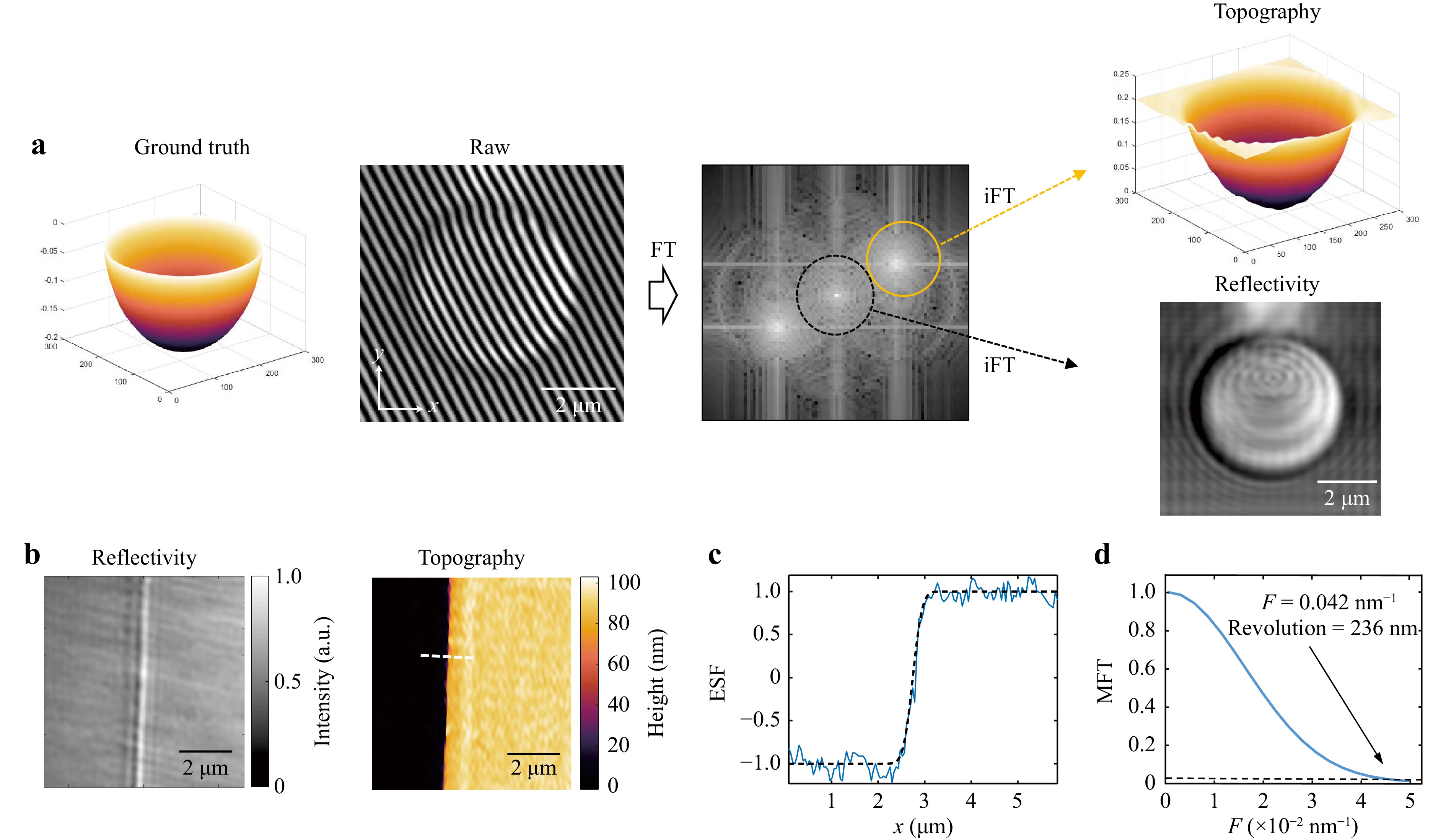
Fig. 2 Dual-modal spatiotemporal imaging and lateral resolution characterisation in 3D topography imaging. a Imaging procedure overview. b Reflective imaging (left) and 3D topography (right) of a standard sample (Bruker DektakXT) with a height of 83.5 ± 2.8 nm, illustrating the limitations of reflectivity imaging in accurately capturing structural details. c Edge spread function (ESF) derived from the normalised height distribution perpendicular to the edge (blue line), fitted with an error function (black dashed line). d Modulation transfer function (MTF) analysis reveals a resolution of 236 nm at an MTF threshold of 3% (black dashed line).
The spatial resolution of 3D topographic imaging is assessed by measuring a sharp edge, which is a common microscopic technique28,29. Here, a standard step sample with an abrupt height change of 83.5 ± 2.8 nm (Bruker DektakXT) was utilised for this purpose. The interference fringe period in the sample plane was 228.8 nm. In contrast to the reflective image that shows only a bright boundary line (left panel in Fig. 2b), the reconstructed topographic image reveals a clear height variation across the step (right panel in Fig. 2b), indicating the distinct characteristics of the two modalities. Reflective imaging modality primarily respond to surface reflectivity, making it impossible to distinguish between surfaces with different heights but identical optical properties. By contrast, 3D topography overcomes this limitation and provides an accurate surface profile. The one-dimensional height distribution along the white lines in the topographic image in Fig. 2b was normalised to a range of 0 to 1 when fitted with an error function. The fitted error function is shown in dashed black in Fig. 2c, and the normalised intensity distribution is shown in blue. Based on the fitted error function, the edge spread function (ESF) was obtained28,29. The derivative of the ESF yields the line spread function, and its Fourier transform represents the modulation transfer function (MTF) (Fig. 2d). Based on the frequency corresponding to a 3% MTF value as the threshold28,29, a spatial resolution of 236 nm was determined for the 3D topographic images.
In 3D topography imaging, the height of an object is derived from the calculated phase using a linear coefficient, as described in Eq. 10. Consequently, the accuracy of phase calculation directly affects the axial resolution of the 3D imaging system. In our system, the interference fringe period is 228.8 nm, corresponding to a phase shift of 2π. Assuming a phase calculation error equivalent to a single pixel on the sample plane, which is 29 nm, this results in a phase calculation error of ${29\;\mathrm{n}\mathrm{m}\cdot 2{\text π}}/{228.8\;\mathrm{n}\mathrm{m}} $. As shown in Fig. 2b, a phase change of 2.87 is calibrated to a height measurement of 83.5 nm. This results in a height calculation error: $ ({29\;\mathrm{n}\mathrm{m}\mathrm{ }\cdot \mathrm{ }2{\text π}}/{228.8\;\mathrm{n}\mathrm{m}})\cdot( {83.5\;\mathrm{n}\mathrm{m}}/{2.87})= 23\;\mathrm{n}\mathrm{m} $. The temporal resolution was determined from the duration of the probe pulse at the sample plane, which was experimentally measured to be approximately 256 fs (refer to Supplementary Note 1).
The calibration results demonstrate that our 3D topography approach enhances the lateral resolution compared to the SPSLM, which requires inclined illumination to use the triangulation method25. For comparison, the lateral resolution of the SPSLM was measured using the same method, yielding a resolution of 457.31 nm (see Supplementary Note 2). In addition, to illustrate the improved reconstruction accuracy of our approach, we reconstructed a crater structure using both simulations and experiments. The results demonstrated that the proposed method yielded a more accurate outcome (see Supplementary Note 3).
-
LIPSS is a widely observed phenomenon that occurs when a material is exposed to laser irradiation30,31. Typically, these structures manifest as periodic grooves or ridges oriented perpendicular to the polarisation direction of the laser beam. This phenomenon has attracted significant attention owing to its potential to modify surface properties such as optical, mechanical, and chemical attributes. Contemporary theories regarding the generation of LIPSS can be classified into two primary categories: electromagnetic models32,33 and self-organisational models34,35. However, it is important to recognise that these two theoretical approaches are not mutually exclusive. Instead, they often exhibit an interplay, indicating a complex relationship between the mechanisms driving LIPSS formation8,30,31.
To fully capture the evolution of LIPSS formation, a two-dimensional LIPSS (2D-LIPSS) was fabricated on a silicon surface using cross-polarised pulse pairs. The fabrication process was monitored using our dual-modal spatiotemporal imaging method. A cross-polarised pulse pair with equal energy and an inter-pulse delay of 19.8 ps was employed as one pump shot. The inter-pulse delay exceeds the time scale of the electron-phonon coupling, which is typically several picoseconds36. Consequently, the second pulse of the pair primarily influenced the molten surface rather than interfering with the electron-phonon dynamics of the first pulse. The diameter of the Airy spot on the sample surface in the experimental setup was ~12.4 μm. The dual-pulse system used has equal energies of 240 nJ in both arms, resulting in an average fluence of 0.21 J/cm2, below the ablation threshold of single-crystal silicon (0.3−0.5 J/cm2)37. Fig. 3 shows the surface topography at different time delays following the arrival of the first, second, and third pulse pair shots. The initial zero-delay time was defined as the moment at which the surface modification first became visible (see Supplementary Note 4).
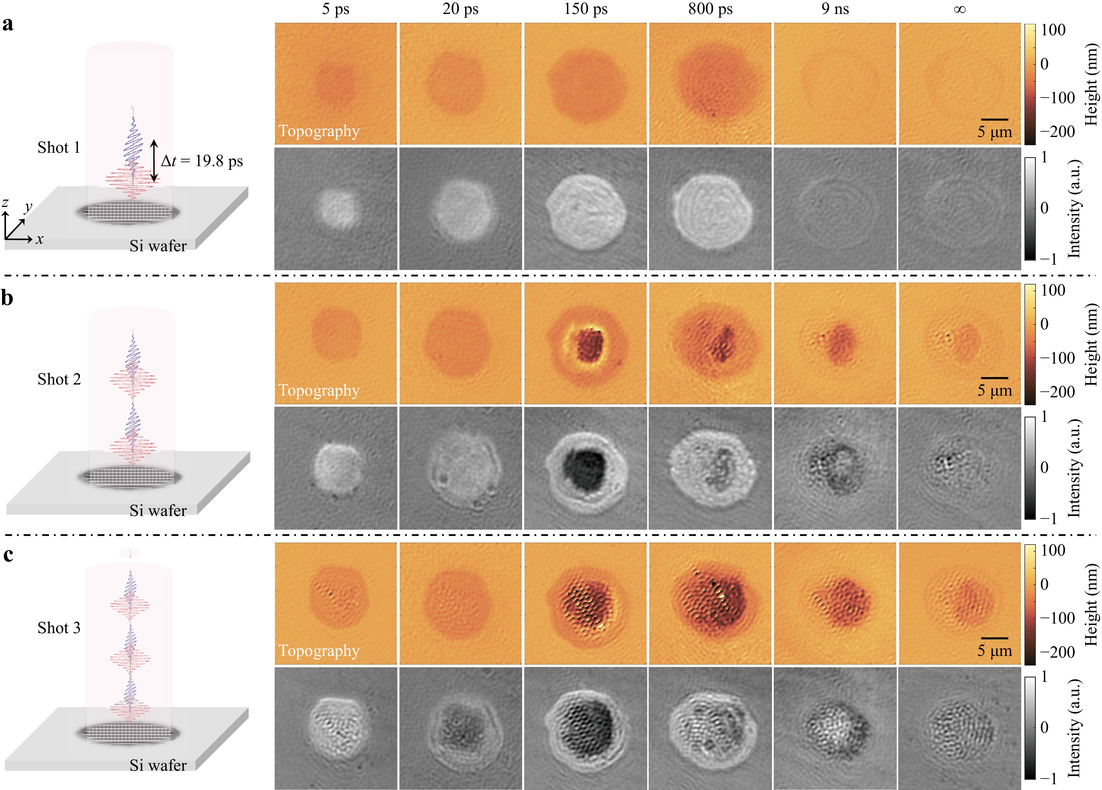
Fig. 3 Dual-modal spatiotemporal imaging of the dynamics of LIPSS formation on a silicon surface irradiated by different shots of cross-polarised pulse pair. Schematic on the left illustrates the silicon surface irradiated by the first a, second b, and third c pulse-pair shots. The upper right columns in a-c show the evolution of the surface topography following each irradiation, while the lower right columns show the reflective images. Each reflective image is obtained by subtracting the image taken with the pump turned off, to eliminate unwanted interference. The time indicated in the figure corresponds to the pump-probe time delay.
The first cross-polarised pulse pair (Shot 1) led to an increase in reflectivity, as illustrated in the lower column of Fig. 3a, which is consistent with previous reports14−17. This increase in reflectivity was attributed to the laser-induced excitation of free carriers and the subsequent ultrafast melting of the material. The generation of free carriers can change the refractive index of a material, leading to an increase in reflectivity. However, considering the Gaussian profile of the pump beam and the fluence dependence of the free-carrier excitation, the reflectivity profile should also exhibit a Gaussian shape, which contradicts the observed flat-top profile. The flat-top reflectivity profile with a sharp boundary (150 ps, Fig. 3a) was more likely due to the thin layer of molten Si resulting from ultrafast melting. This ultrafast melting is triggered by the strong modification of inter-atomic forces owing to the excitation of a large fraction of valence electrons into the conduction band38. The corresponding topographic images (5−800 ps, upper column, Fig. 3a) reveal shallow craters, which may be a result of the density change when solid silicon is melted into the liquid state39. Fig. 3a also shows that the second pulse, arriving at 19.8 ps, intensified the melting process, resulting in a larger and deeper melted area (20 ps, Fig. 3a). In accordance with previous observations, the molten surface persisted for a few nanoseconds before solidifying17,40. However, upon resolidification of the liquid silicon layer, the surface became relatively flat (infinity, Fig. 3a).
The second cross-polarised pulse pair (Shot 2) was triggered manually with a sufficiently long time interval relative to the first shot to ensure that the induced morphology had fully solidified. Upon exposure to the second cross-polarised pulse pair, the surface underwent another cycle of melting and solidification, as shown in Fig. 3b. Notably, the ablation threshold decreases at this stage, potentially because of the generation of defects or changes in the material induced by the first shot, a phenomenon known as the incubation effect41. At a delay time of 150 ps during this cycle, ablation was observed at the centre of the melted region. This was indicated by the presence of a darkened area at the centre of the structure in the reflective image, which was previously identified as ablation17,37. Despite the challenges posed by low reflectivity in observing the detailed features within the ablation zone, the topographic image revealed a distinctly deepened central region with a protruding rim (150 ps, upper column, Fig. 3b), providing additional structural insights. The onset of ablation from the centre of the Gaussian pump laser spot indicated that the maximum energy was deposited there through intense electronic excitation and subsequent electron-phonon coupling. Following the initiation of ablation, periodic structures began to emerge in two directions within the ablation zone surrounded by molten Si with a flat surface. As the ablation area expanded, the LIPSS morphology gradually encompassed the molten surface. As the material cools down (800 ps - ∞, Fig. 3b), a noticeable reduction in depth is observed in the time-resolved topography images, potentially attributed to the smoothing effect of liquid flow during the ablation process. Irradiation with a third cross-polarised pulse pair (Shot 3) further enhanced the LIPSS morphology in both directions, as evidenced by the significantly more pronounced intersecting periodic ripples in the topography images from a delay time of 140 ps to 2 ns (upper column, Fig. 3c).
These experimental results provide valuable insights into the formation mechanism of LIPSS. Upon the initiation of ablation, the ablated region exhibited periodicity in both orthogonal directions, highlighting the combined effect of the two cross-polarised laser pulses. This modulated ablation behaviour can be explained using the surface plasmon polaritons (SPPs) model. The generation of free carriers and ultrafast melting induced a metallic state in the material, supporting the generation of SPPs33. The interference between the SPPs and incident light within the molten region modulates energy deposition and promotes the formation of periodic microstructures on the surface, which are further enhanced by repeated irradiation. This modulated ablation behaviour implies that energy deposition modulation occurs during the initial stages of the laser-matter interaction, potentially owing to electromagnetic scattering or interference, and is further enhanced through repeated irradiation shots. The simultaneous emergence of ablation and the intersecting LIPSS pattern significantly differs from the self-organisation mechanism, in which LIPSS are typically formed through the evolution of both the hydrothermal motion of the molten layer and ablation over a longer timescale34,35.
As another illustration of the application of our dual-modal spatiotemporal imaging, we demonstrated the erasure and reformation of the LIPSS using laser pulses with different polarisations. Initially, we fabricated a LIPSS pattern on a silicon surface using three x-polarised femtosecond laser pulses. The LIPSS pattern was oriented in the y-direction perpendicular to the polarisation of the laser. When exposed to y-polarised laser pulses, the pre-fabricated LIPSS pattern gradually disappeared, whereas a new LIPSS pattern slowly formed and was oriented in the x-direction. The dual-modal evolution of the entire process is illustrated in Fig. 4.

Fig. 4 Dual-modal spatiotemporal imaging of the formation of new LIPSS structures on a pre-fabricated LIPSS structure on a silicon surface. Schematic of the left illustrates the silicon surface being irradiated by three x-polarised pulses a and subsequently by two y-polarised pulses b-c. The upper right columns in a-c display the evolution of the surface topography, while the lower right columns represent corresponding reflection intensity maps. The time indicated in the figure corresponds to the pump-probe time delay.
During the process of pre-fabrication, the material undergoes a sequence of melting, ablation, and re-solidification stages following the arrival of the pulse. The generated LIPSS is evident after three pulses, as shown in Fig. 4a. For simplicity, only the final solidified patterns for the first and second pulses are shown. The first pulse induces a shallow crater without visible LIPSS generation. The second pulse produced a slight LIPSS pattern at the centre of the crater, whereas the third pulse reinforced this pattern. The topography image (Infinity, Fig. 4a) shows that the solidified pattern exhibits vertically aligned ripples with a period of 770 nm perpendicular to the polarisation direction of the laser.
After the LIPSS pattern fully solidified, the structure was exposed to a single laser pulse with y-polarisation. The evolution of topography and reflectivity following laser exposure is shown in Fig. 4b. Exposure to a y-polarised pulse resulted in an increase in reflectivity, which can be observed in the first reflective image (1 ps) in Fig. 4b. This increase in reflectivity aligns with the experimental results shown in Fig. 3, which we attribute to ultrafast melting. At 100 ps, a dark zone characterised by a significantly decreased reflectivity was observed in the central region. This is indicative of the onset of ablation. The molten surface surrounding the ablation area appeared nearly flat, suggesting that the structure in this region was erased by melt flow. Although the reflective image shows a dark central region due to reduced reflectivity, the topographic image distinctly shows intersecting periodic structures in both directions within the ablation area. This observation implies that the structure was formed through a combination of pre-existing features and electromagnetic scattering effects of the y-polarised laser pulse. As the material cooled, a periodic structure emerged in both the horizontal and vertical directions on the silicon surface (Infinity, Fig. 4b).
As shown in Fig. 4c, the second y-polarised pulse enhanced the formation of ripples oriented perpendicular to the polarisation direction. At a specific delay time of 40 ps, when the second pulse triggered ablation again (see Supplementary Visualisation 3), horizontal ripples became the dominant feature until solidification occurred. The results demonstrate that the pre-fabricated structure is gradually erased through melting, whereas new ripples are formed as a result of the modulated ablation induced by the modulated absorption of laser energy.
To provide a clearer demonstration of the formation and erasure of the LIPSS, a fast Fourier transform (FFT) analysis was conducted on the time-resolved topography images. The FFT procedure is shown in Fig. 5a-c, where point P in the spatial frequency spectrum denotes the spatial frequency of LIPSS with a period of 770 nm, consistent with previous studies25,29. Fig. 5d, e present the temporal evolution of the normalised FFT power at point P for the two experiments shown in Figs. 3, 4, respectively. To clearly illustrate this evolution, the experimental data were fitted using shape-preserving interpolation.

Fig. 5 Spectral analysis of the time-resolved topography image. a A central region of approximately 7 μm × 7 μm in the topography map (black box) is selected to perform the Fourier transform. b, c The spectral intensity at point P along x- b and y-direction c shows the spatial frequency of LIPSS. d, e The spectral intensities in both directions are plotted as a function of time delay after irradiation of coupled d and independent operations e using pulses with cross polarisations. The red, green, and purple backgrounds in d represent the temporal evolution after the incidence of each pulse pair. The red and purple backgrounds in e represent the temporal evolution after the incidence of x-polarised and y-polarised pulses, respectively.
When cross-polarised pulse pairs were used, as shown in Fig. 5d, the spectral power in both the x- and y-directions increased with the arrival of each pulse pair. During each exposure, the spectral intensities increased rapidly, followed by simultaneous gradual stabilisation in both directions. This observation highlights the collective contribution of the cross-polarised pulses during early energy deposition, which is consistent with the observations presented in Fig. 3. Fig. 5e shows the results of independent operation referring to Fig. 4. Specifically, the spectral power in the x-direction increased gradually under y-polarised pulse irradiation. However, it experienced a significant decrease when subjected to an x-polarised pulse owing to the induced melting effect. Moreover, the power in the y-direction exhibits a noticeable increase after ablation and gradually stabilises until solidification. Detailed information on the dual-modal evolution of the silicon surface in the two experiments can be found in Supplementary Visualisations 1-4.
-
We demonstrated a dual-modal spatiotemporal microscopy approach that combines a pump-probe technique with an interferometric imaging system. This method enables simultaneous two-dimensional reflectivity and 3D topography imaging with remarkable spatial and temporal resolutions of 236 nm and 256 fs, respectively. The temporal resolution can be further improved by utilising a pre-chirped probe pulse to compensate for the group-velocity dispersion of the lenses. In contrast to traditional methods that rely solely on reflected intensity data to study ablation dynamics, our dual-modal spatiotemporal microscopy provides insights into both changes in material properties and the formation of three-dimensional structures. This approach provides a more comprehensive understanding of the interactions between ultrafast lasers and materials. Thus, it can serve as a valuable tool for comprehending and controlling the complex dynamics involved in ultrafast multi-pulse laser-material interactions. By employing this method, the formation and erasure of the ultrafast dynamics involved in double-pulse LIPSS under various irradiation conditions were investigated.
Currently, the spatial and temporal resolution of our system is constrained to approximately 236 nm and 256 fs, respectively, by the optical diffraction limit and dispersion of the lenses used. The spatial and temporal resolutions of the system can be further enhanced in future studies. For example, to improve the spatial resolution, water- or oil-immersion objectives that feature a high numerical aperture (NA), can be employed. Shorter-wavelength probe light, such as the third harmonic at 267 nm, can be employed to further enhance resolution. In addition to these physical approaches, the integration of super-resolution imaging algorithms with multiple phase-shifted images29 has the potential to surpass the diffraction limit and further extend the spatial resolution capabilities. For temporal resolution improvement, a pre-chirped pulse can be used to compensate for the group-velocity dispersion induced by the lenses and objective lens in the optical path, minimising the pulse width at the sample plane. A shorter pulse source can also enhance temporal resolution.
The interference techniques used in this technology are inherently susceptible to environmental vibrations. In this study, femtosecond pulses were employed as probe pulses to capture a single pulse per image. Consequently, the effective exposure time for each image is on the femtosecond scale, which significantly reduces the influence of vibrations. To correct for the phase shift induced by vibrations across different images, the unablated area outside the pump laser exposure for each image served as a reference plane to calibrate the height variations. In our topographic modality, the height of the object was determined by analysing the phase of the reflected probe light. However, sharp height transitions can result in phase discontinuities surpassing the range of 0−2π, posing challenges for phase unwrapping and potentially resulting in incorrect height reconstruction. The reflectivity sensitivity is also a crucial factor in experimental measurements, with sufficient reflectivity to ensure a high signal-to-noise ratio. Therefore, our method is applicable to a variety of materials including semiconductors, metals, and dielectric materials. For materials exhibiting significant transient absorption at 400 nm, the probe wavelength can be optimised to achieve better reflectivity by replacing the BBO crystal with a supercontinuum generation setup.
The dual-modal spatiotemporal microscopy technique used in this study represents a novel approach for studying and controlling the ultrafast dynamics of laser-material interactions. Their ability to be generalised to various materials offers a broad range of applications in advanced material-processing technologies, including precision manufacturing and surface modification. The dual-modal imaging capability with high spatiotemporal resolution not only provides a comprehensive understanding of the ultrafast process in laser processing but also enables real-time feedback on the fabrication process. This capability is crucial for quality control and process optimisation in manufacturing environments, allowing immediate adjustments to maintain the desired specifications. In the automotive, aerospace, and biomedical industries, where the customisation of surface functionalities is essential, this technique enhances the utilisation of LIPSS to modify surface properties, including wettability, adhesion, and biocompatibility30.
-
This research was supported by the Guangdong Major Project of Basic and Applied Basic Research (2020B0301030009), National Natural Science Foundation of China (62175157, 62375177, and 92150301), Shenzhen Science and Technology Program (JCYJ20210324120403011, RCJC20210609103232046), Research Team Cultivation Program of Shen Zhen University (2023QNT014), and Shenzhen University 2035 Initiative (2023B004). The authors acknowledge the Photonics Center of Shenzhen University for the technical support.
Dual-modal spatiotemporal imaging of ultrafast dynamics in laser-induced periodic surface structures
- Light: Advanced Manufacturing , Article number: (2025)
- Received: 29 October 2024
- Revised: 11 March 2025
- Accepted: 25 March 2025 Published online: 14 May 2025
doi: https://doi.org/10.37188/lam.2025.030
Abstract: The interactions between ultrafast lasers and materials reveal a range of nonlinear transient phenomena that are crucial in advanced manufacturing. Understanding these interactions during ultrafast laser ablation requires detailed measurements of material properties and structural changes with high temporal and spatial resolutions. Traditional spatiotemporal imaging techniques relying on reflective imaging often fail to capture comprehensive information, resulting in predominantly qualitative theoretical models of these interactions. To overcome this limitation, we propose a dual-modal ultrafast microscopy system that combines two-dimensional reflectivity and three-dimensional topography imaging. By integrating pump-probe techniques with an interferometric imaging system, impressive spatiotemporal resolutions of 236 nm and 256 fs were achieved. Furthermore, using this system, we successfully examined the dynamics of laser-induced periodic surface structure formation, strengthening, and erasure on Si surfaces. The results demonstrate that the dual-modal spatiotemporal imaging technique can serve as a robust tool for the comprehensive analysis of ablation dynamics, facilitating a deeper understanding of the fundamental physics involved and enabling more accurate optimisation of ultrafast laser fabrication processes.
Research Summary
Spatiotemporal Dual-Modal Imaging: Tracking Ultrafast Laser-Matter Interaction Dynamics
A novel microscopy system developed by Changjun Min's group at Shenzhen University enables simultaneous observation of ultrafast reflectivity and topography changes with unprecedented precision. Combining pump-probe techniques with interferometric imaging, this dual-modal system achieves remarkable 236 nm spatial and 256 fs temporal resolutions. Unlike conventional methods limited to 2D reflectivity data, the new approach captures 3D space-time dynamics during laser-material interactions. They successfully applied the system to study the complete dynamics of laser-induced periodic surface structures on silicon - from formation and strengthening to erasure. By simultaneously mapping transient structural and optical variations, the technology provides deeper insights into fundamental physics and enables precise optimisation of ultrafast laser fabrication processes.
Rights and permissions
Open Access This article is licensed under a Creative Commons Attribution 4.0 International License, which permits use, sharing, adaptation, distribution and reproduction in any medium or format, as long as you give appropriate credit to the original author(s) and the source, provide a link to the Creative Commons license, and indicate if changes were made. The images or other third party material in this article are included in the article′s Creative Commons license, unless indicated otherwise in a credit line to the material. If material is not included in the article′s Creative Commons license and your intended use is not permitted by statutory regulation or exceeds the permitted use, you will need to obtain permission directly from the copyright holder. To view a copy of this license, visit http://creativecommons.org/licenses/by/4.0/.

 DownLoad: