


-
Technologies for building big optical systems don’t naturally benefit from commercial forces that create exponential growth, as they do for photonics or digital data communication systems. Metrics of progress with optics have shown slow growth. It took 200 years to get from Newton’s first abrasively polished reflecting telescope to the 0.8m reflective glass-mirror telescope that was first manufactured by Foucault in 18651. It was another 100 years before we progressed to the 5m Hale and then another 50 years before we doubled this world’s largest aperture with the 10m Keck or Grantecan telescopes2, 3. It was technology like electromagnetic mirror actuators that enabled “modern” (50-year old) telescopes of relatively lower mass.
Some trends in the mass and cost of large ground-based telescopes are illustrated in Fig. 1. To manufacture an extremely large telescope we must overcome this mass-cost scaling relationship. While there has been advancement in many opto-mechanical subsystems of these telescopes, changing this paradigm is difficult. For example a common technology for nearly 400 years has been to abrasively polish thick, massive, mirrors.
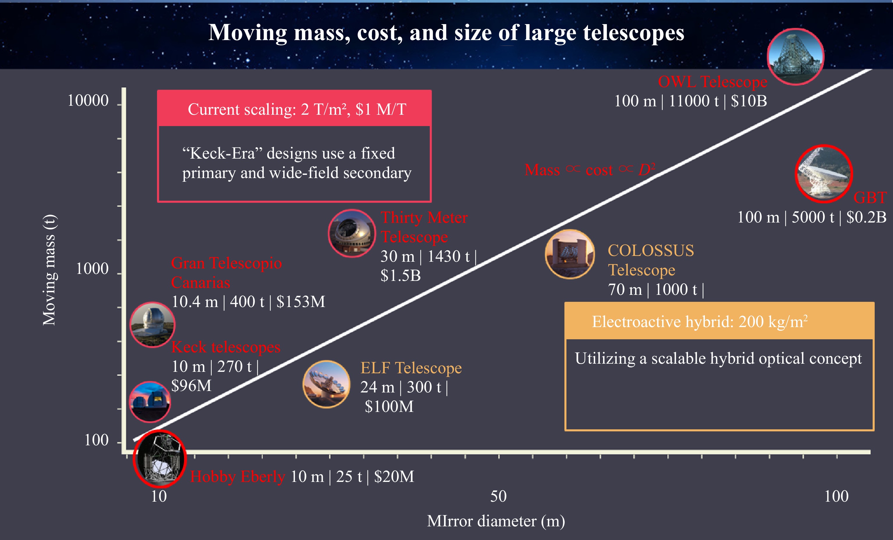
Fig. 1 Mass, cost, and size data from historical and engineering documents of planned large ”Keck-era” ground-based telescopes illustrate almost 100 year trends. In round numbers every tonne of moving telescope mass is about $1M in telescope optics and structure cost and creates about 0.5m in telescope aperture.
Large optical telescopes are inherently opto- mechanical systems and their cost scales with their mass4. An important metric of progress is their total moving mirror and mechanical support mass per optical collecting area. Here advancement has also been slow. From the 1949 Hale telescope to the 2008 Keck telescopes this ratio decreased by less than an order of magnitude from 24 to 2.7 T/m2. In contrast information technology capabilities grew by 5 or 6 orders of magnitude over a similar period following the so-called “Moores Law.”
The Laboratory for Innovation in opto-mechanics (LIOM)5 at the Instituto de Astrofísica de Canarias (IAC) has embarked on a 5 year study to accelerate the development of relatively inexpensive large optical telescopes. LIOM is currently building the Small-ELF (SELF), a 3.5-meter prototype that will serve as a test-bed for the future ExoLife Finder (ELF), a 50-meter scale telescope we hope to construct. ELF is designed to use Fizeau interferometry to achieve unprecedent resolution and sensitivity for exoplanet imaging. LIOM is exploring new ways of polishing mirrors, building and controlling the mechanical structures that support these optics, and measuring and controlling the incident optical wavefront needed to solve key observational problems.
The approach LIOM is taking asks the question “can we create lightweight telescopes, perhaps with non-conventional optical configurations, mechanical structures, optical mirrors, and modern wavefront measurement and correction strategies borrowed from new communication and manufacturing technologies?”. The telescope we’d like to design and build targets the problem of finding life around planets outside the solar system. To do this requires separating the reflected starlight off the planet from the star. Astronomers call this “direct imaging”. This means we’re interested in optical systems that can have a narrow field-of-view (FOV), perhaps just a few arcseconds, and enormous photometric dynamic range capability. A laudable goal is to achieve raw sensitivity of 10−8 of the stellar flux in a region within about 1 arcsecond of the central star. A dedicated telescope with this capability could make images of the surface of nearby exoplanets using data inversion techniques, perhaps sufficient to see even signs of advanced exolife civilizations6, 7.
-
“Flattening” the distorted wavefront from a distant star, in order to separate the exoplanet’s light from starlight, requires correcting for the Earth’s atmospheric seeing, telescope diffraction and imperfect optics-induced wavefront distortions. As long as the wavefront can be measured with uncorrelated errors we can decrease the scattered light in the image around the star by increasing the telescope diameter $ D $ and the adaptive optic degrees of freedom (DOF) in proportion to the telescope pupil area. Fig. 2 illustrates how the pupil size and phase errors create scattered light in the telescope Point Spread Function (PSF). The PSF (figure inset) becomes more narrow as the diffractive resolution and number of wavefront phase correction DOF improve with increasing telescope size. The resulting scattered light background decreases as the telescope gets bigger, especially near the central core where resolution and phase noise decrease the relative background brightness faster than $ \sigma_\phi^2/D^2 $. Assuming $ N_p = D/R_0 $ measurements across the pupil to approximately correct the wavefront implies that the scattered brightness per angular resolution element in the $ N_p\times N_p $ sampled image is approximately
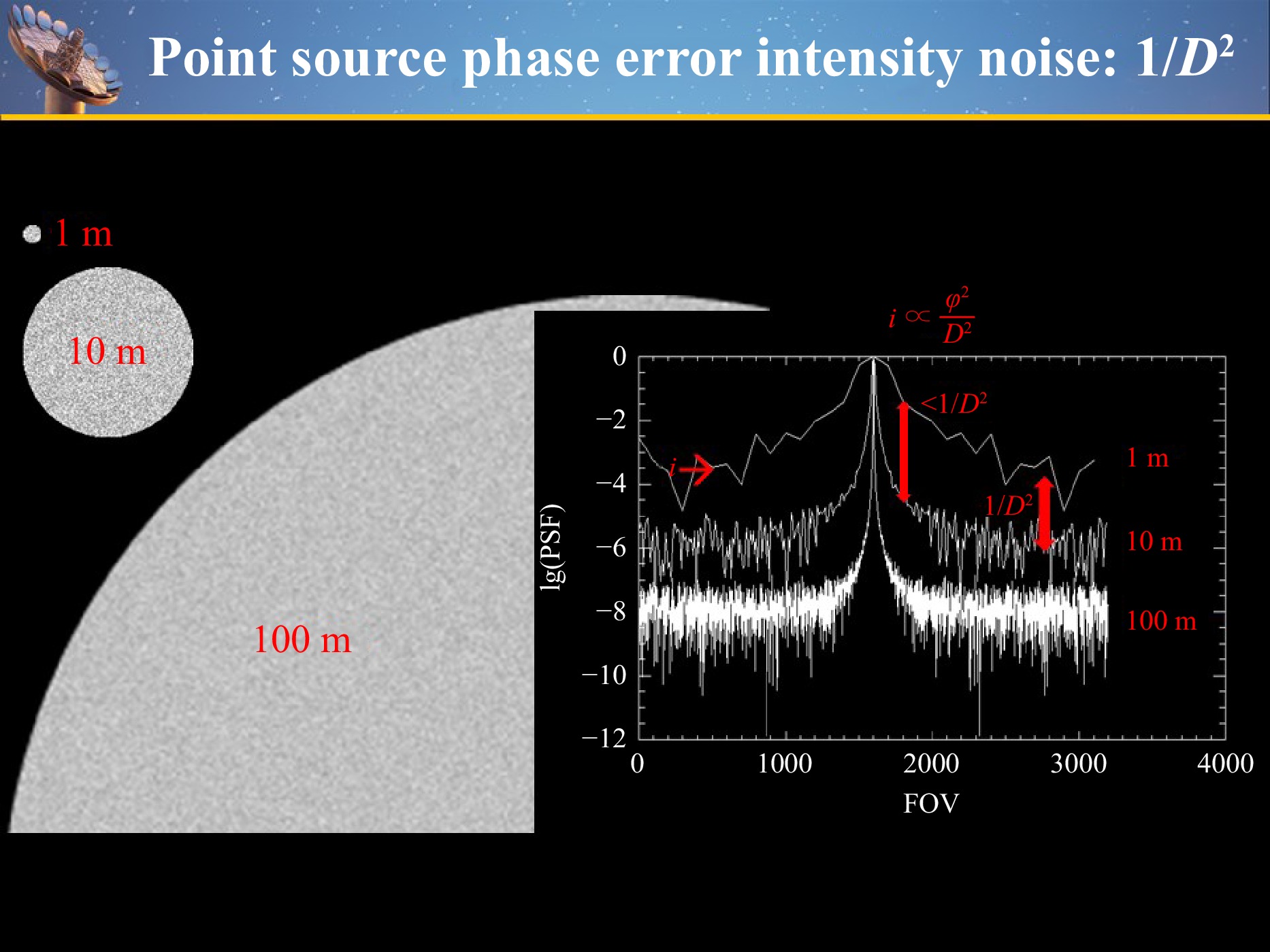
Fig. 2 The scattered light background versus pupil diameter for $\sigma_\phi$=0.005 illustrates the scattered light background amplitude problem
$$ I_{scat} \approx I_0\sigma_\phi^2/N_p^2 $$ (1) where $ I_0 $ is the central (stellar) image brightness and $ \sigma_\phi $ is the rms wavefront phase error. Eq. 1 makes it clear that a larger telescope aperture, with constant phase measurement errors, improves scattered light per resolution element as $ 1/D^2 $.
A simple calculation on a circular pupil of diameter D illustrates how diffraction and phase errors affect a star’s scattered light background due to small atmospheric phase errors. The diffracted and scattered electric field at image field angle $ {\bf{k}} = (k_x, k_y) = 2{\text π} (\theta_x,\theta_y)/\lambda $ is $ \|E\|^2 \propto I_{scat} $. In terms of the pupil integral this is
$$ E({\bf{k}}) = \int_{pupil}[1+i\phi({\bf{x}})]exp(i{\bf{k}}\cdot{\bf{x}})d^2{\bf{x}}. $$ (2) Here $ \phi({\bf{x}}) $ is a small wavefront phase error referred to the pupil and $ {\bf{x}} = (x,y) $ are pupil coordinates. With $ \phi = 0 $ the modulus squared of Eq. 2 gives the telescope PSF. We approximate the phase errors in each $ R_0 $ patch, $ \phi ({\bf{x}}) $, to be a normally distributed independent variable in the calculations below.
Explicitly, a pupil of diameter $ N_p $ = 1024 with random gaussian phase errors, and with phase standard deviation $ \sigma_\phi = $1, yields the total scattered and diffracted intensities shown in Fig. 3 in terms of the star flux $ f_{star} $. Diffraction from a circular aperture creates a diffuse brightness that falls asymptotically like $ I(\theta)\propto\theta^{-3.2}. $ When this diffraction is faint enough the random phase errors described in Eq. 1 define a scattered diffuse light background floor. In this example if $ R_0 $ were 5 cm and $ D = 50 $ m then the largest angle plotted in Fig. 3 is 4” with $ \lambda = 1\ $ μm. Thus we see that even with $ \sigma_\phi = 1 $rad the scattered light beyond about 0.4” is less than $10 ^{-6} $. In order to achieve lower diffracted and scattered light at smaller angles will require modifying the pupil to create a diffraction pattern with, for example, dark holes. Such a synthesized PSF is described in more detail below. With an Adaptive Optics (AO) system of $ N_p = D_0/R_{AO}\approx 1000 $ actuators along a side, $ \sigma_\phi<0.1 $rad,is readily achievable and a synthesized (dark spot) diffraction pattern could reach scattered light levels of $ f_{scat}\approx 10^{-8}f_{star} $.
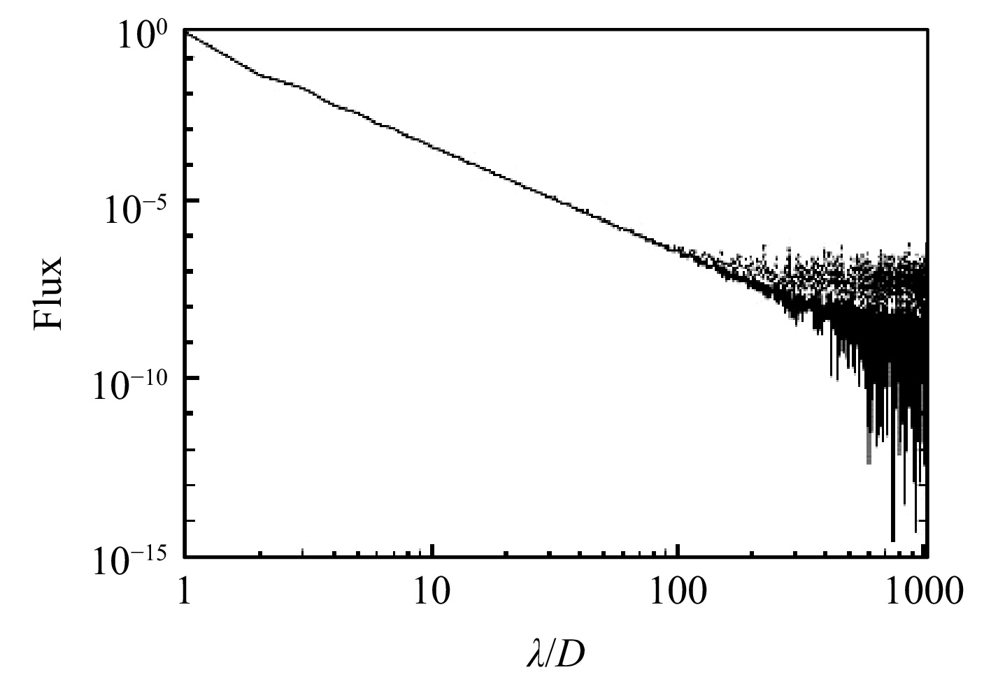
Fig. 3 The diffracted and scattered flux of a $N_p$ = 1024 circular pupil with gaussian wavefront phase errors $\phi_{rms} = 0 (solid~ line) $ and 1(dotted). The flux is normalized to unity at the center and the x axis shows angle in units of $\lambda/D$ radians.
-
Current plans for large ground-based telescopes8−10 are based on effectively rigid segmented primary mirrors created by active mirror controls. Monolithic secondary or tertiary mirrors then create the final telescope image. We note that these large primary mirrors must be stiffened electromechanically over 10’s of meters to the level of a few 10’s of nanometers to reach diffraction limited performance. This is in contrast to the atmospheric phase errors ahead of the primary that can already be several optical wavelengths. This is intrinsic to wide FOV optical systems. Decreasing the field-of-view to a few arcseconds and requiring a bright star in a field-of-view of perhaps only a few arcseconds means that an entirely different high-resolution, adaptive, and coronagraphic optical system becomes feasible.
In this case we don’t require extraordinary stiffness from the large tracking mirror-supporting optical structure but can use active and adaptive opto-mechanical controls. As we describe below active optics in the secondary mirror structure can now yield a high resolution image with very high photometric dynamic range. This means the optical system may be much lighter than a ”Keck-era” large telescope. The telescope volume can also be smaller because of the faster focal ratio possible with a narrow FOV. This is a Fizeau interferometer11 where light from the common path of each mirror segment interferes in the final image plane, at or close to the final science image, and with minimal non-common path optical errors. One example is illustrated in Fig. 4. In our prefered design atmospheric-fluctuation timescale optical pathlength distortion (OPD) corrections can now be made with intrinsically small and responsive secondary M2 segments committed to each M1 subaperture.
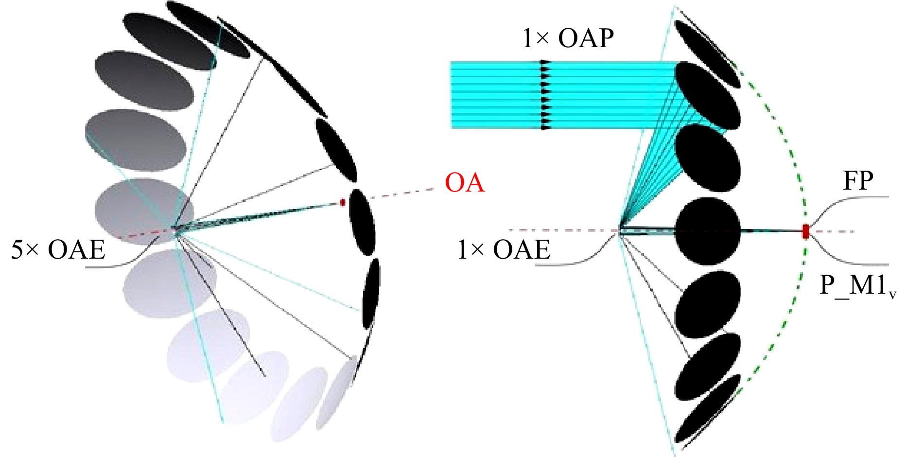
Fig. 4 A ring of identical off-axis parabolas combined with a secondary optical structure of small off-axis elliptical mirrors creates a free-space beam combiner without delay lines at the gregorian focus of the parent telescope surfaces.
-
We now describe how free-space subaperture beam combining can be used for Fizeau imaging interferometry to synthesize a PSF that matches the exoplanet direct imaging problem. We seek a configuration that minimizes the number of distinct optical elements and that allows image domain (common path) wavefront measurements and correction. We use M reflective primary mirror elements as the pupil tracker payload. We let $ \vec x_i $, where $ i = 1...M $, denote the pupil center coordinates of each subaperture. We further assume each element has the same shape defined by a two-valued pupil function of $ P(\vec x) = $ 0 or 1. The coherent wavefront electric field and intensity at the optical focus are then $ I(\vec\theta)\propto\|E(\vec\theta)\|^2 $ where $ \vec\theta $ is the image angle. If each subaperture introduces a wavefront phase $ \phi_i $ and vector wavefront tilt $ \Delta\vec\theta_i $ (radians per meter in x and y direction) error, then Fraunhofer diffraction gives the image electric field at $ \vec\theta $ as
$$ E(\vec\theta)\propto\sum\limits_j\int d^2xP(\vec x) \exp{i\{{2{\text π}\over\lambda}\vec\theta\cdot(\vec x-\vec x_j) +\phi_j+\Delta\vec\theta_j\cdot\vec x\}} $$ (3) Integrating and taking the squared modulus yields the image intensity
$$\begin{array}{l} I(\vec\theta)\propto\sum\limits_{jk}\exp\{2\pi i[\vec\theta\cdot(\vec x_k-\vec x_j)+(\phi_j-\phi_k)]/\lambda\}\cdot \\ \;\;\;\; \;\; \;\; \cdot\tilde P(\vec\theta+\lambda\Delta\vec\theta_j/2\pi)\tilde P^*(\vec\theta+\lambda\Delta\vec\theta_k/2\pi) \end{array} $$ (4) Eq. 4 describes the telescope PSF. It illustrates how the geometry and phase errors of the pupil scatter the bright central starlight. We see that the PSF is also a complex fourier sum over baselines, $ x_j-x_k $ modulated by the subaperture information contained in $ \|\tilde P\| $ as it is perturbed by wavefront tilt errors. $ \tilde P $ is the fourier transform of the aperture function and $ ^* $ indicates complex conjugation. For circular pupil elements without tilt errors ($ \vec\theta_i = 0) $ this term reduces to a subaperture Airy function. The form of Eq. 4 also explains why it is the phases, $ \phi_i $ of the subapertures, not their tilts $ \vec\theta_j $, that determine the primary form (including dark spots) through the exponential dependence on the phases.
If the baselines are non-redundant (no baseline vectors are colinear) then phase error difference pairs are directly determined by the distinct orthogonal angular fourier coefficients of the intensity speckle pattern. This property has previously been used to find efficient algorithms for aligning segmented mirrors using non-redundant pupil masks11.
An odd-numbered ring of M mirrors yields M(M-1)/2 non-redundant baselines. If these mirrors are identical off-axis parabola segments then they can become a convenient free-space beam combiner without complex interferometric delay lines. Fig. 4 illustrates how a collection of M identical off-axis telescopes cut from a parent parabolic pupil, and an elliptical secondary mirror surface form the basis of a SELF.
The agile telescope pupil diffraction pattern can be dynamically changed using each of its circular subapertures12. By changing the optical path length or phase of each M1-M2 segment, an almost arbitrary diffraction pattern can be synthesized. These degrees of freedom may be used to create, for example, a wide or deep hole in the telescope diffractive PSF. They might also be used to solve for a PSF null over a larger wavelength bandpass. In general we will synthesize a PSF that highly attenuates diffracted starlight from an arbitrary part of the image where we wish to measure the faint reflected light of an exoplanet. This coronagraphic PSF is created at the telescope pupil before the image plane. This contrasts with conventional segmented telescopes where a post-focus coronagraph only partially removes diffracted light after it has been scattered by the telescope’s primary and secondary optics.
Fig. 5 illustrates an example of a numerical solution for a dark hole within the angle $ \lambda/D $ of the image core. Here we numerically solved the least-squares problem that minimizes the diffracted intensity (Eq. 4) within a chosen region $ (\vec\theta ) $ of the image plane by varying the phase or piston DOF ($ \phi_i $) of the 15 subapertures. For simplicity the overall subaperture Rayleigh diffraction profile was not included here in the PSF calculation. Fig. 5 was obtained with Powell minimization. This $ 10^{-8} $ contrast solution is unrealistic as it does not include noise but it illustrates the form of the optical phase variation around the distributed telescope pupil. A feature of this nulling solution is that the hole in the PSF can be close to the central star in the image plane. This is a discrete pupil-plane coronagraph phase solution, analogous to the continuous vortex coronagraph that has been described for other telescopes13.
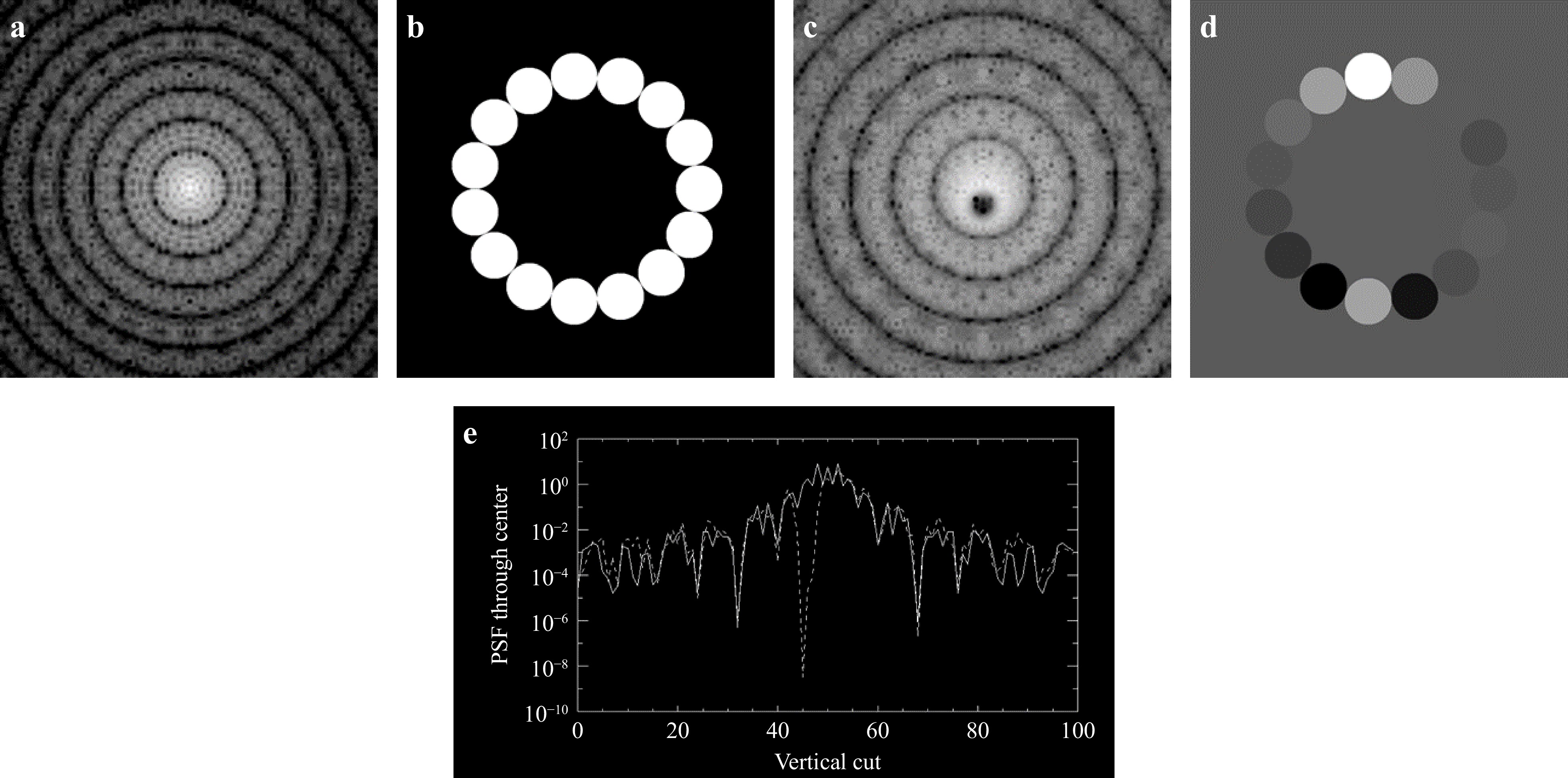
Fig. 5 a PSF of diffraction-limited ELF, b Pupil geometry of a, c PSF of phased ELF pupil, d Grey-scale representation of phase (0-360deg) of 15 segment discrete nulling (”vortex”) coronagraphic ELF pupil c, e Vertical cut through PSF core for nulling solution (dashed) and diffraction-limited (solid) PSF.
The effects of random phase noise on the Fizeau telescope scattered light are especially benign. For example if the pupil-plane phase noise satisfies zero mean and is uncorrelated on spatial scales larger than $ R_0 $ then from the modulus of Eq. 2 we deduce that this noise creates scattered light, $ I $, that satisfies
$$ I({\bf{k}}) = PSF({\bf{k}}) +\sigma^2_\phi \times PSF({\bf{k}}) $$ (5) Eq.5 shows that the uncorrelated phase noise is modulated by the PSF. Thus in the region of a dark hole the atmospheric phase noise is strongly attenuated.
It is possible that our limiting noise will come from the systematic errors in the determination of the piston phases of each subaperture (c.f. panel ’D’ in Fig. 5). Fig. 6 illustrates a vertical cut through the perturbed PSF (the stellar scattered light profile) as a function of the rms piston subaperture noise (in radians). In this example we take the dark hole to be within the nominal Rayleigh diffraction angle $ \lambda /D $ of the full telescope aperture.
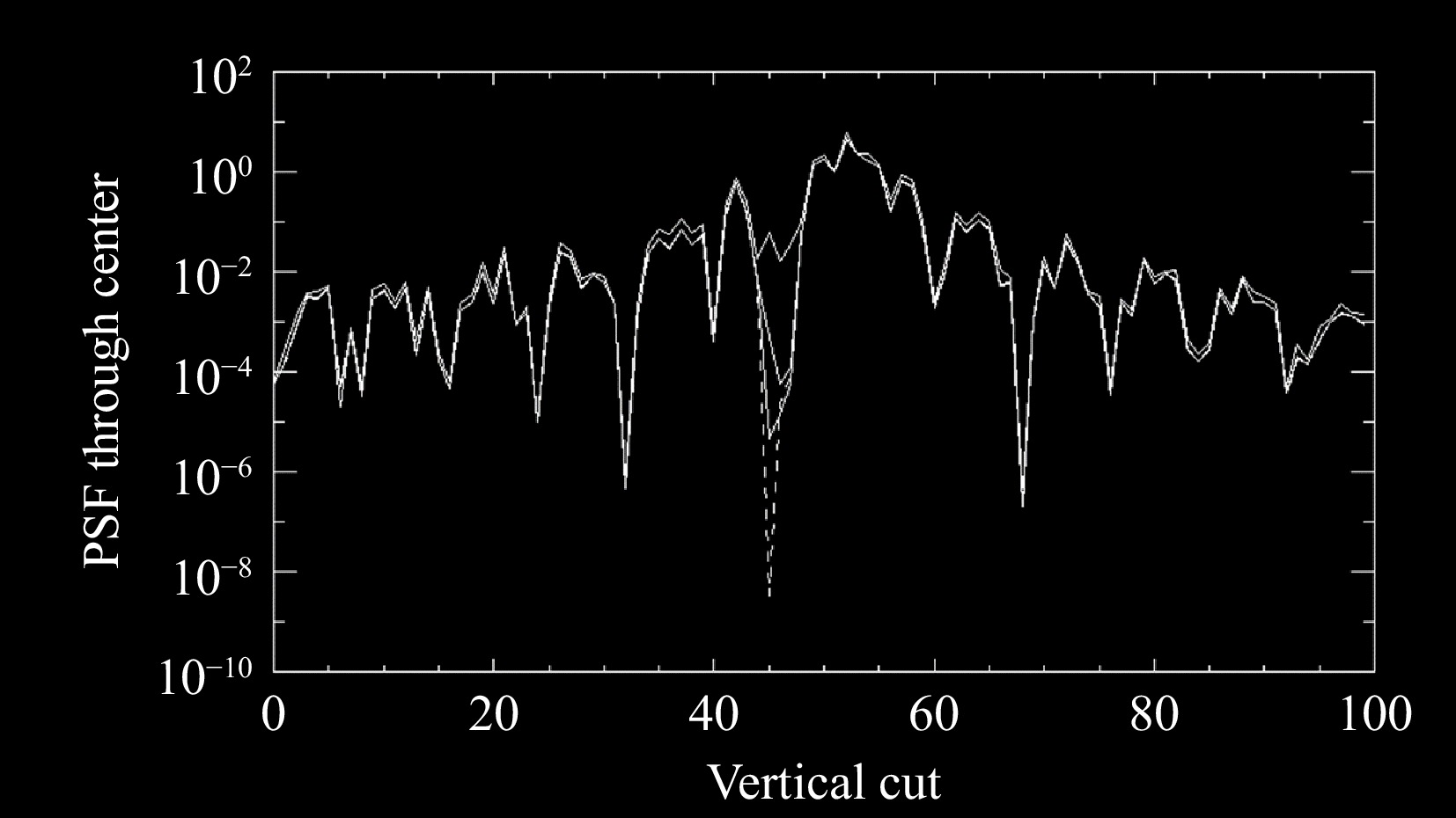
Fig. 6 Vertical cut through the scattered light PSF due to rms systematic wavefront piston phase errors in the subapertures. The dashed line shows the no phase error solution, successive solid lines near the vortex ”hole” at pixel 45 correspond to rms phase errors of 0.1, 0.01, and 0.001 radians
To set the scale of this error we note that the background scattered light brightness varies as the square of the rms piston phase errors. At best these errors are determined by the number of photons detected at each subaperture. In the visible, a 0.5m diameter aperture will absorb about $ 10^{10} $ photons/s from a 0 magnitude star. For classical photon detection the piston wavefront phase measurement error is approximately $ \sigma_\phi\approx \sqrt{1/N_\gamma} $, where $ N_\gamma $ is the number of photons per actuation time interval that intercept the subaperture. If the dark hole attenuates the diffracted peak stellar surface brightness by $ 10^{-4} $ then a point-like exoplanet source significantly fainter than this average brightness should be detectable, depending on the signal integration time and PSF stability. Our goal with the Small ELF (SELF) path-finder will be to measure any $ >10^{-5} $ sources within the diffraction core. If the atmospheric piston wavefront error is stable to $ \sigma_\phi <0.01 $ over any 0.01s interval then we’ll need a star brighter than about 10th magnitude to measure subaperture phases sufficient to see $ 10^{-5} $ circumstellar sources.
-
Astronomical interferometers with a discrete number of geometric baselines typically use delay lines on separated tracking optical mounts. Large discrete baseline interferometers can achieve high angular resolution14, but because the Fourier components of the image are reconstructed by scanning the variable discrete baseline combinations that are created by the telescopes as they move through the sky, their achievable signal-to-noise and dynamic range is orders of magnitude less than a tracking filled aperture. To observe exoplanets many orders of magnitude fainter than the central star requires an imaging interferometer.
Some complexities of interfering images, as in a Fizeau interferometer, are described for the ARGOS 3-mirror system15. Combining images from collimated beams using distinct tracking telescopes with a relatively wide FOV like Argus requires unusual precision to match the subaperture pupil beam magnification and shear alignment that the narrow FOV SELF/ELF avoids.
The Large Binocular telescope (LBT)16 is the world’s largest imaging interferometer with two 8.4m gregorian telescopes on a common alt-az tracking mount. It is being used for 10 μm wavelength nulling interferometry and Fizeau imaging of, for example, circumstellar environments17. On a longer timescale the LIFE space mission has been proposed as a cryogenic 10 μm experiment for doing nulling Fizeau spectroscopy from independent satellite subapertuers in space18 in order to search for exolife.
The LBT interferometer (LBTI) is a pathfinder for large ground-based telescope systems and offers lessons for future Fizeau telescopes like ELF. For example, the LBTI’s nulling performance illustrates some practical limitations from mechanical vibration, atmospheric optical pathlength coherence effects, and thermal wavelength detector and background noise limitations. The SELF and ELF telescopes will mitigate many LBTI and ARGOS issues by: using a small FOV with 15 nonredundant subapertures, a single tracking mount and parent off-axis parabola optic for all subapertures, an active opto-mechanical structure for active vibration damping, and small very agile M2 phasing optics that work in the near infrared to do beam combining at the gregorian telescope focus.
-
The LIOM project at the Instituto de Astrofisica de Canarias is a 5 year research program started in 2023 that is aimed at advancing technologies that could allow future ground-based construction of the world’s largest telescope, suitable for detecting life on nearby exoplanets. The LIOM group is now building the 3.5m diameter SELF telescope as a technology pathfinder and science demonstration for exploring and proving some technologies required for a 50m-scale ELF.
-
The SELF telescope uses 15 0.5 m diameter subapertures with a 3.5 m outer diameter. They are identical off-axis parabolas and each works with a 2 cm diameter 2mm thin curvature polished off-axis ellipsoidal secondary mirror as illustrated in Fig. 4.
In order to interfere SELF’s subaperture images at the parent optics’ gregorian focus it must maintain the optical pathlengths and pupil alignments. This must occur in the presence of atmospheric and telescope vibration noise. Clearly, SELF will be a complex active telescope. After a bootstrapping algorithm to achieve approximate geometric and optical path length alignment the SELF degrees of freedom will be controlled by intelligent algorithms that use the phase information contained in the speckles of the common gregorian image. In order to align the telescope to within its Machine Learning capture range, it starts from alignment systems described conceptually in Fig. 7.
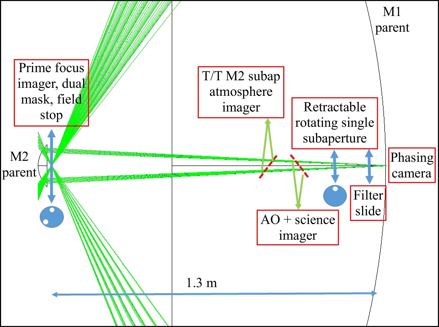
Fig. 7 The SELF active optics assembly is illustrated here starting from the M2 subapertures. Two (out of 15) beam paths from the M1 subapertures are drawn. Three retractable assemblies and secondary atmospheric and phasing imagers control the M2 tip/tilt/piston (T/T/P) DOF. The dual- and single addressable subaperture masks provide coherence and geometric beam alignment bootstrap opportunities. Additional M1 T/T/P and thermal distortion M1 despace control are associated with the M1 subaperture mirror mount assembly.
LIOM is testing its system concepts and more detailed models with laboratory experiments. Our laboratory “nanoELF” model is being used to test phasing, vibration, and alignment algorithms on a simple two mirror system. Fig. 8 illustrates a comparison between model and phased 2-mirror nulling in the lab.
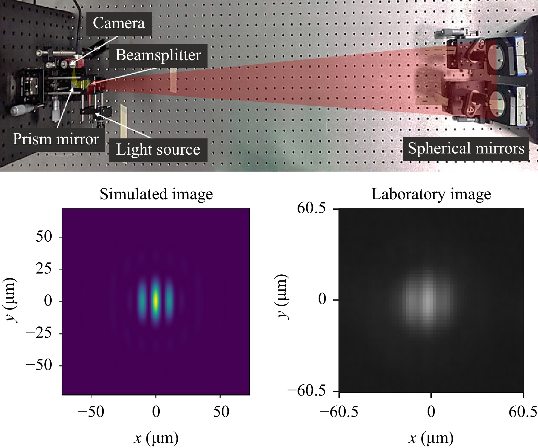
Fig. 8 Nano-ELF laboratory prototype for testing co-phasing, nulling, and alignment protocols. Light from a fiber is reflected by two spherical mirrors and forms an image on a camera. A beamsplitter and prism mirror separate the input and output light paths, which are illustrated for clarity. At the bottom, the simulated diffraction pattern (left) is compared to the image obtained in the laboratory (right) for a 1064 nm light source.
The LIOM/SELF project has several important sequential goals: 1) To demonstrate a 3.5 m distributed pupil telescope with a mass significantly less than conventional ground telescopes, 2) to create an opto-mechanical structure that achieves stiffness using a shear-minimized opto-mechanical structure that attenuates vibration dynamically, 3) to create primary mirror segments lighter than any existing 4m-scale telescope, and to create curvature polished secondary mirror segments, 4) to demonstrate the active SELF M1-M2 optical system and a PSF null near the image core, and within a year of the telescope phasing demonstration, 5) to implement an adaptive optic system that allows $ 10^{-4} $ dark spot nulling within $ \lambda/D $ of the image core.
Some of the novel technical solutions SELF and ELF will develop are described below.
-
The field of exoplanet research has made remarkable progress over the past 30 years, beginning with the ground-breaking discovery of a hot Jupiter orbiting a Sun-like star with the radial velocity technique19. That same year marked the discovery of the first unequivocal brown dwarfs20, 21, confirming a theoretical prediction made three decades earlier22. Their numbers of both types of objects has increased significantly since then with a wide range of physical properties (Fig. 9). One of the most exciting and ambitious goals in modern astronomy is the search for life on other planets, with the aim of determining whether our Solar System is truly unique or exceptional. The discovery and detailed characterization of Earth-like planets, along with efforts to understand the origins of life, are set to be the main astronomical priorities for the largest ground-based telescopes and space missions in the coming decades.
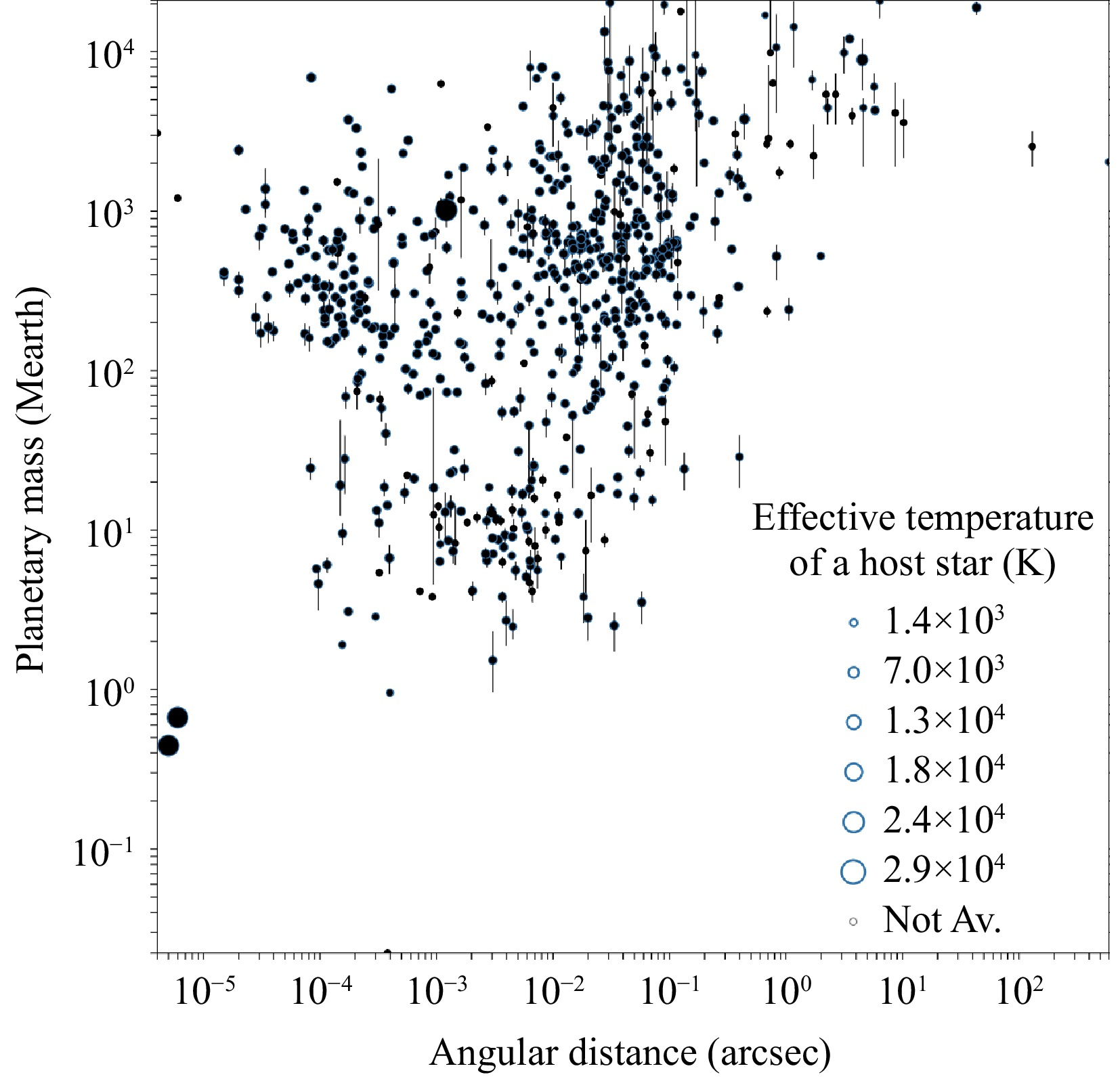
Fig. 9 Planetary mass (Earth units) vs orbital separation in arcsec for the census of exoplanets and planetary-mass objects with mass measurements from the exoplanets.eu website. The top right region with separations beyond 1 arcsec would be the range of action of Small-ELF, while ELF should be able to access any exoplanet with separations larger than a few mas from its host star.
The proposal for a 50-m class telescope, the ExoLife Finder, presents both scientific and technological challenges. The scientific challenges, discussed throughout this paper, center on the search for life on exoplanets and the exploration of their surfaces on a continental scale. To image a planet and map its atmosphere, large apertures are needed to collect as much light as possible in the infrared wavelengths ($ Y $, $ J $, $ H $ filters) with, at the same time, high spatial resolution ($ \leq $0.1 arcsecond) and dynamic range ($10 ^{-4} $ to $10 ^{-8} $). The main goal is to enhance contrast at closer separations and increase the number of observable stars, targeting the majority of telluric planets, which are predominantly located between 1 and 4 AU. This initiative will strongly complement radial velocity studies and the Gaia astrometric mission23−25. On Earth, atmospheric biomarkers exist in sufficient quantities to signal the presence of life. A 30-m telescope could be sensitive enough to detect such biomarkers on exoplanets like Proxima Centauri b and may even be able to map their surfaces with sub-continental precision. Additionally, the $ J $-band filter, centered at 1.25 micrometers, is optimal for detecting and characterizing terrestrial exoplanets, as it contains spectral features that are key indicators of chemical processes associated with liquid water and carbon-based life.
Before advancing with the ExoLife Finder (ELF), we are developing a prototype, known as Small-ELF, to validate the technology and demonstrate that Fizeau interferometry can be effective in this context. Small-ELF will serve as a crucial precursor for the next generation of large optical telescopes, surpassing the current generation of extremely large telescopes such as the E-ELT, TMT, and GMT. While Small-ELF will have reduced sensitivity and capabilities, and cannot observe Earth-like exoplanets, as a dedicated telescope it will provide unprecedented information on circumstellar environments and some exoplanet photometry. Specifically, one of our key goals is to detect $ \epsilon $ Eridani b26−29 through direct imaging, along with other bright exoplanets that are sufficiently separated from their host stars (typically more than one arcsec). Second, we aim at characterising masses and physical properties of substellar and planetary-mass companions, e.g. the case of VHS J125601.92$ - $125723.930−33 to the nearest and brightest stars to the Sun. Other potential targets for Small-ELF are members of the nearest open clusters, star-forming regions, and young moving groups, where several substellar companions have been announced over the past decade at reasonable projected physical separations (see review by34 and35). In Fig. 9 we observe that about 20 widely-separately brown dwarfs and planetary-mass companions to bright stars will be reachable by Small-ELF in the coming years for in-depth spectroscopic characterisation.
-
Shaping glass by abrasively grinding the optical surface is slow and expensive. The process requires successive layers of material to be removed with diminishing-sized abrasive particles in order to recover a final optically smooth surface. Material removal depends on the tooling size and pressure and the associated frictional heating. The deformation of substrates that are less than many cm thick also adds to the “non-determinism” of a necessarily highly repetitive grinding and polishing process.
It has been known since 1905 that the shape of thin glass can be affected by its surface tension. Twyman discovered that by roughening one side of a flat plate that the molecular surface tension is locally diminished and, in response, the substrate curves outward to make the rough (“work”) surface convex. This induced local curvature increases with decreasing glass thickness36. This effect can be used to shape large mirrors – we call it “curvature polishing”37.
Much of the vast world production of mm-scale thick “window” glass involves floating a thin layer of molten glass over smooth liquid tin. Consequently, on small scales this glass can be smoother than abrasively polished surfaces. Glass produced this way can have less non-specular scattered light than typical ground-glass mirrors by an order of magnitude. Fig. 10 illustrates representative surface shape measurement of commercial float-glass. It is quite smooth at high spatial frequencies with a powerspectral surface height density falling like $ k^{-3} $ where the spatial frequency is $ k $. Precisely shaping float-glass on cm-scales, without grinding the front optical surface, can create superior reflective mirrors. The Twyman effect allows this. Fig. 11 illustrates such glass shaping.
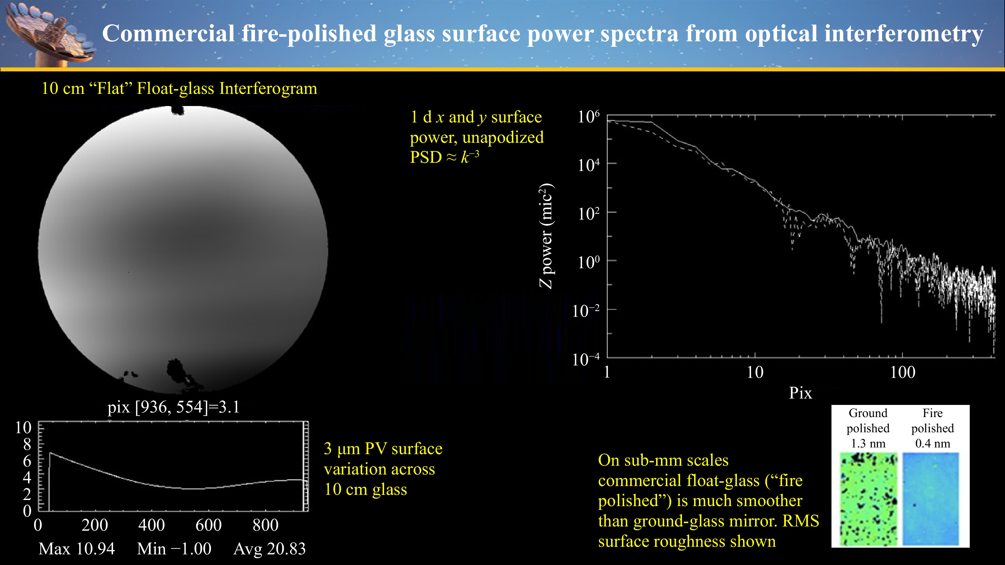
Fig. 10 Manufactured float-glass is smoother than abrasively polished mirrors. This figure illustrates interferometric 10cm and microroughness measurements and an apparent surface roughness power spectrum that varies as $\propto k^{-3}$.
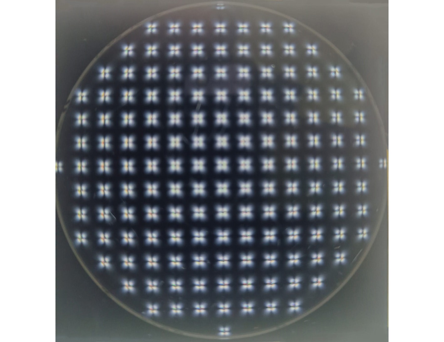
Fig. 11 The induced stress from a grid of laser spots is visible by observing the glass between crossed polarizers
Curvature polishing of thin glass can be achieved using techniques that change the local surface tension on the non-optical, back work surface of glass. The local glass stress created by millisec bursts of a 10 μm laser on a glass substrated are shown in Fig. 12. Here the glass is viewed between crossed polarizers and each of the ”x” patterns reveal the glass stress birefringence generated from a constant duration grid of laser spots.
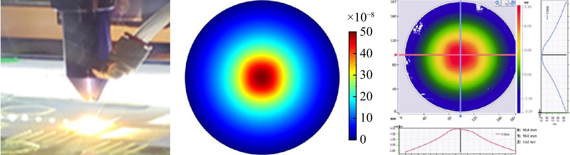
Fig. 12 Curvature polishing can be done with a 10$\mu$m wavelength laser (left panel). The center panel shows a model of the glass shape induced by the applied local curvature map. Right panel shows how the modeled shape change agrees with the observed interferometrically measured shape on 10cm diameter, 2mm thick glass. The full surface height range in these figures is about 5 μm.
The front optical surface is not touched so that it retains its smooth small-scale shape from the glass ”float” manufacturing process. Research groups in Maui and Lyon have shown how infrared CO2 lasers, polymer coatings, or surface roughening can shape mm-scale thickness float glass. To date this has been demonstrated with small area 3D printer machines that apply a predetermined induced stress distribution (Fig. 11) by laser, polymer, or surface roughening onto 10cm-scale diameter glass plates (Fig. 12)38−43. This shaping process is deterministic in that the glass optical surface height correction $ {\textit z}(x,y) $ is determined by the applied curvature change $ c(x,y) $ on the back surface of the glass plate, as determined by
$$ \nabla^2 {\textit z}(x,y) = c(x,y) $$ (6) Polishing then requires calibrating the 3D printer laser pulse duration to the applied curvature, $ c $. We measure the glass surface $ {\textit z}(x,y) $ to compute $ c(x,y) $ from Eq. 6. This curvature is then corrected to the required target mirror curvature value with a 3D gantry CO2 laser.
-
One path toward creating large stress-insensitive opto-mechanical structures, while decreasing mass, involves adapting biomimetic concepts – using biological systems as mechanical templates. We adopt “tensegrity”, a term originated in the 1960’s by R. Buckminster Fuller44 as an architectural and structural notion that emulates biological systems. Using rigid “bones” subject to compressional forces linked only by tensional “tendons” can create stiff mechanical structures with minimal mass. Compressional stiffness is much greater than shear stiffness. The ratio of compressive to shear deformation in a truss of length $ L $ and cross section $ s^2 $ is simply
$$ \delta_{comp}/\delta_{shear} = s^2/4L^2 $$ (7) Building a mechanical system that is stiff in the right directions and that has no shear stresses is the goal of a low mass opto-mechanical telescope and mirror support structure. Equation 7 suggests that a no-shear tensegrity structure could, theoretically be much lighter than conventional rigid structures.
Tensegrity structures approximate a no-shear structure by linking each “bone” (truss) with flexible “tendons” (cables or thin steel trusses) that are linked with slip joints and hinges. No truss joins another without a flexible coupling. Each tendon must be pretensioned and the entire structure could, in principle, connect the optical payload to the drive and tracking systems. The algorithmic process of creating the bone and tendon geometry that links tracker and mirrors is called ”form-finding” and there are several entropic and mechanical energy-based minimization algorithms for solving this problem45. One example of a tensegrity structure that could support a parabolic optic is illustrated in Fig. 13. This is not a practical telescope support structure, yet. The SELF telescope makes a step toward a lower mass shearless structure by using highly tensioned thin steel elements, like spokes in a bicycle wheel.
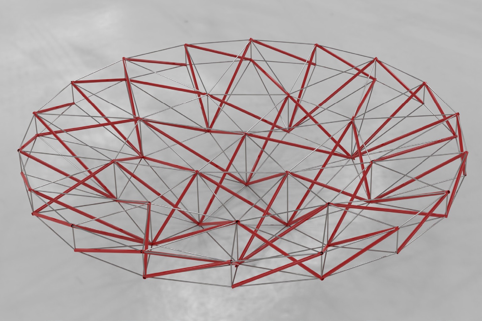
Fig. 13 This shows a simple geometric tensegrity form-finding solution for a parabolic mirror backing structure
The SELF telescope in Fig. 14 supports its optical subapertures with a pseudo-tensegrity bicycle wheel structure. In addition to lower mass, another advantage of a tensegrity-like object is that it is a natural structure for applying active control. The adaptive telescope structure is realized through active stiffness with dynamic tension actuators, offering both precision and lightweight performance. The active vibration damper provides essential structural damping, maintaining accuracy and stability under dynamic conditions.
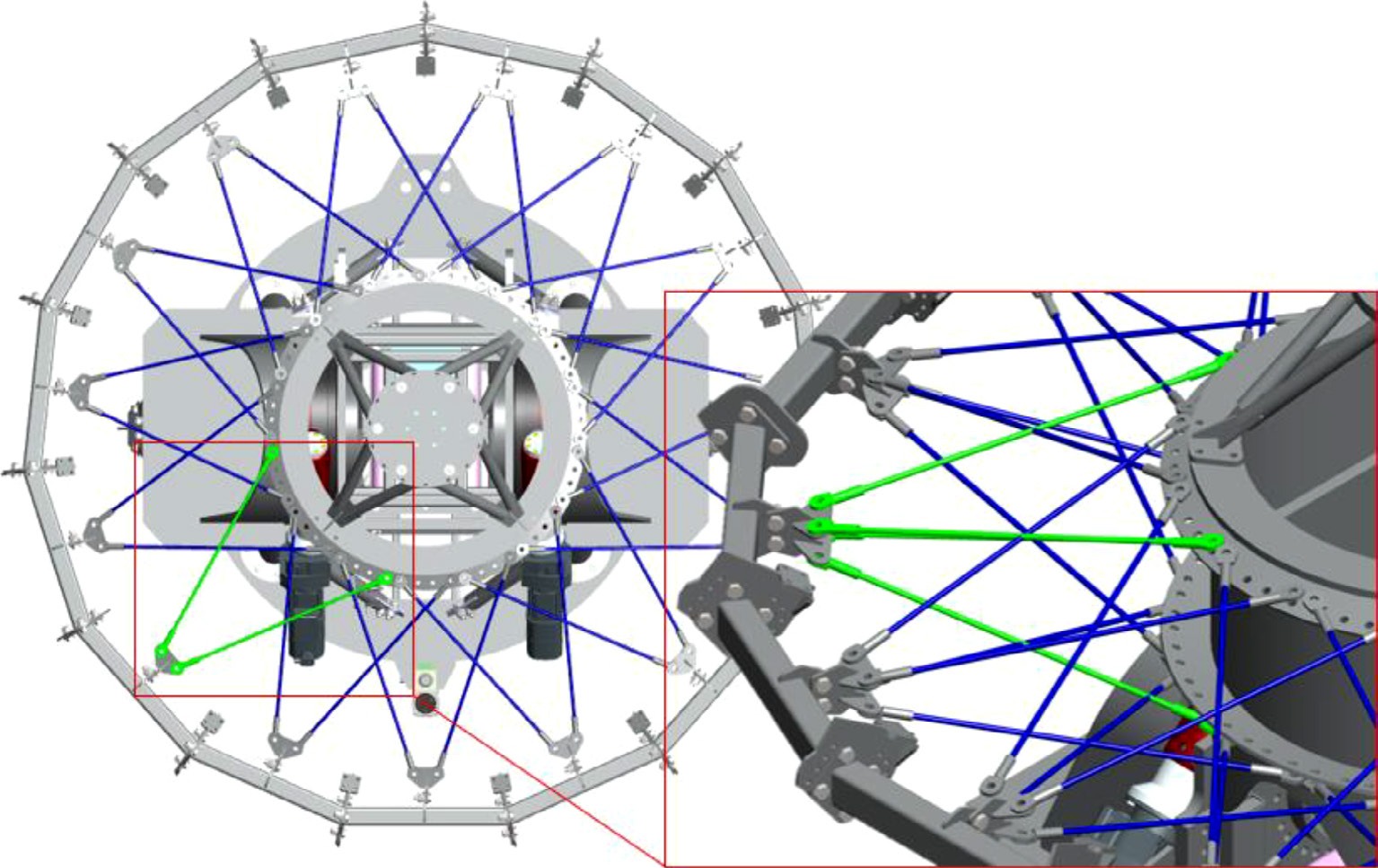
Fig. 14 The Small ELF (SELF) reduces the telescope structure mass with a tensegrity-like bicycle ring structure. It is expected to be completed in the Canary Islands in 2026.
Thin mirrors require a more complex backing structure to connect the optical payload to the telescope tracking structure. The 15 mm thick SELF mirrors are perhaps the thinnest mirrors yet to be used in a 4-m class optical telescope. In general as a mirror’s thickness decreases the complexity as measured by the number of joins or flextures of the mechanical truss structure will increase to maintain a small gravitational peak-valley deflection of the mirror surface, z, compared to the wavelength of light. If we characterize a periodic lattice-like mirror backing structure that supports the optic with support point separation $ a $ then it follows that
$$ {\textit z}\propto a^4/t^2L_0 $$ (8) 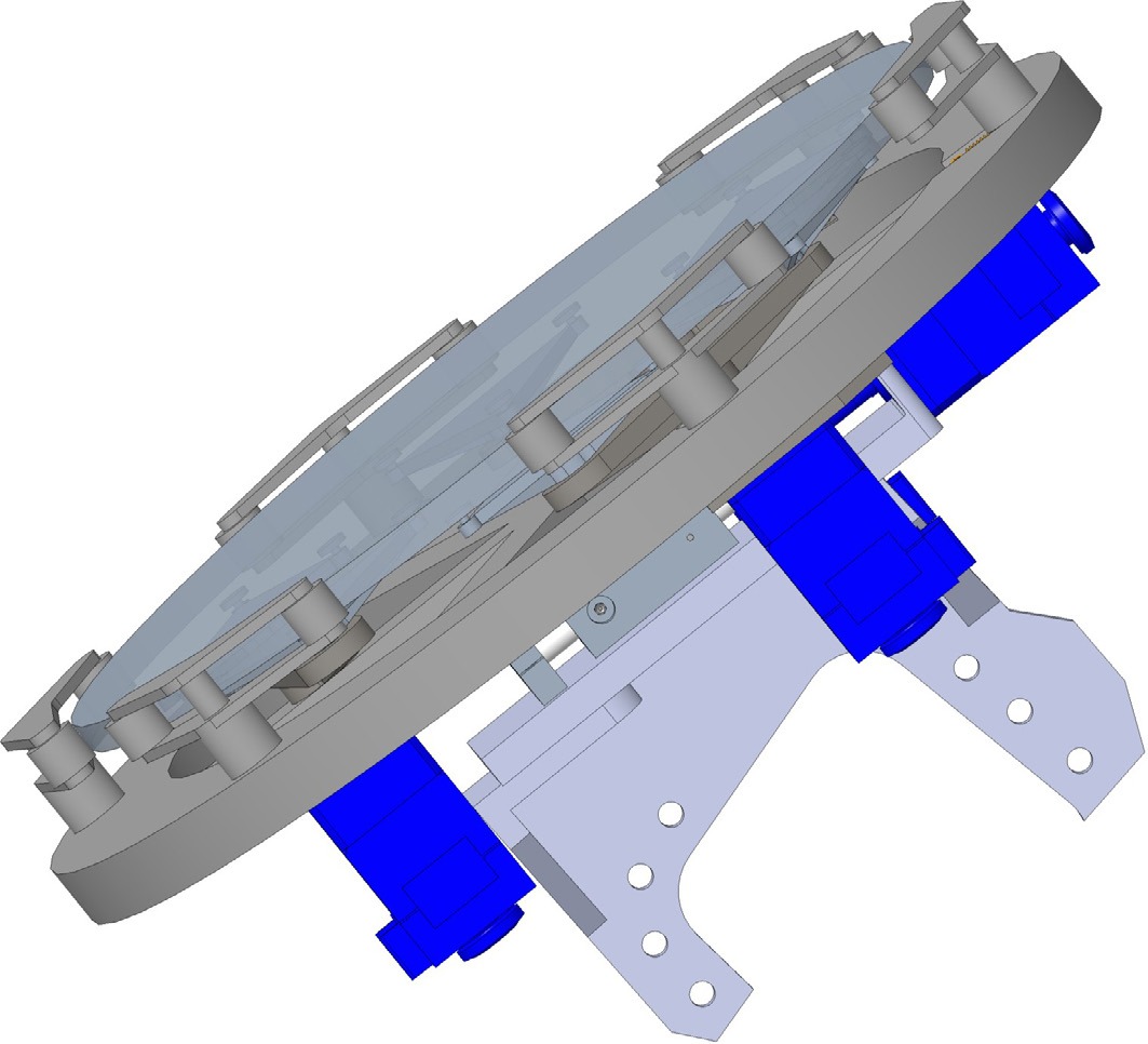
Fig. 15 SELF’s M1 sub-apertures consist of an off-axis parabolic mirror with a diameter of 500 mm and a thickness of 15 mm
where for glass (and steel) the mechanical material properties are described by a characteristic length, $ L_0 = $ 2 Mm12 and the proportionality constant is approximately unity. For reference, if a typical mirror creates an rms wavefront error of, say, 60nm, this corresponds to peak-valley (surface) sag of about $ {\textit z} = $‘160 nm and with a mirror backing truss spacing of $ a = 26 $ cm would allow a mirror as thin as $ t = 12 $ cm. As Eq.8 illustrates, decreasing the thickness requires a more complex mechanical backing structure (smaller $ a $ and more joins) or some other source of stiffness in order to maintain the optical quality surface shape.
The SELF’s M1 consists of 15 sub-apertures, each configured as an off-axis parabolic mirror with a diameter of 500 mm and a thickness of 15 mm. The main challenge in designing the support for M1 lies in maintaining the optical precision of the mirror and ensuring that the segments remain continuously aligned. Structural deformations caused by gravity, temperature fluctuations, and other environmental factors can misalign the segments, compromising image quality. To correct these deviations, the support system incorporates actuators that make real-time adjustments. These actuators not only maintain the precise alignment of the segments but also correct phase errors, ensuring that the light waves from the different segments arrive simultaneously and in phase at the focal plane.
To mitigate the effects of external forces, such as gravity, M1 is supported by a system of distributed point supports. Based on detailed numerical studies by46 Nelson, Lubliner, and Mast (1982), the optimal number of support points has been determined to be 18. This arrangement ensures an effective distribution of loads across the entire mirror, minimizing deformations and ensuring that the optical surface remains within the necessary limits to produce high-quality images. The support design is based on the theory of thin plate deflection, where the location and number of support points are optimized to minimize geometric distortions and optical blur. In M1, the 18 support points are arranged in concentric rings, optimizing the load distribution and avoiding localized deformations that could degrade the resulting image quality. The triangular grid arrangement for these support points provides greater efficiency by minimizing surface tilt errors and image blur. Consistent with Eq. 8 the rms wavefront error is about 40 nm.
The support system not only manages axial forces, which act perpendicular to the mirror surface, but also radial forces, which manifest parallel to the mirror as the telescope changes its angle relative to the zenith. The radial system of M1 consists of 6 lateral supports, each equipped with two support points. This arrangement is designed to provide uniform and stable support along the entire edge of the mirror, distributing lateral forces in a balanced manner. Each of the six lateral supports distributes the lateral forces between two contact points with the mirror’s edge, spaced every 30°, ensuring that the loads are balanced and stress concentrations that could cause local deformations are avoided. This design is based on the Cosine Lateral Force Radial Support47.
In addition to the support points, the radial system includes a preloading mechanism, which ensures that the contact between the lateral supports and the mirror is always under weak compression. In M1’s design, two of the six lateral supports are located at the bottom of the mirror and are more rigidly fixed, acting as the main anchor points. The remaining four supports apply the radial preload, compensating for lateral forces and keeping the mirror centered. The radial preload ensures that the mirror remains firmly in place, distributing forces evenly along the mirror’s edge. This type of design is especially useful in avoiding backlash, even when the telescope changes orientation and experiences variations in gravitational load, significantly improving image stability.
Active correction is crucial for maintaining the precise alignment of the mirror segments under thermal and gravitational distortion. Piston, tip, and tilt must be controlled (in combination with active M2 optics) in order to maintain the optical path and geometric co-alignment of the subapertures. To correct these deviations, each M1 segment is equipped with three axial actuators that control the M1 tip, tilt, and piston alignment. This design ensures precise force distribution and facilitates the necessary adjustments in segment alignment. Additionally, a radial actuator moves the entire mirror support system radially (decenter) in order to correct for the thermal distortion of the SELF optical structure.
-
The Fizeau interferometer requires precise alignment and cophasing of the subapertures. The optical path difference (OPD) between segments must be controlled to a small fraction of the wavelength. Fig. 6 suggests it must be controlled to a few 10’s of nm in order to achieve deep optical nulling.
Machine learning approaches may keep up with the real-time and high-cadence required to align the secondary mirrors. In order to do so, the system is solely relying on focal-plane sensing at the detector. The problem is formulated as a regression task, in which the images at the focal plane of the telescope are employed as input, and the output is the set of piston, tip and tilt (PTT) values for each M2 subaperture required for cophasing the SELF telescope.
Fraunhofer propagation was considered to simulate SELF’s optical system, and the Kolmogorov model to generate synthetic atmospheric phase screens, using the HCIPy package48 in Python. Fig. 16 displays the simulated optical system in which the error added and its effect are observed on the speckle pattern for the piston (Fig. 16a) and tip and tilt (Fig. 16b), respectively.
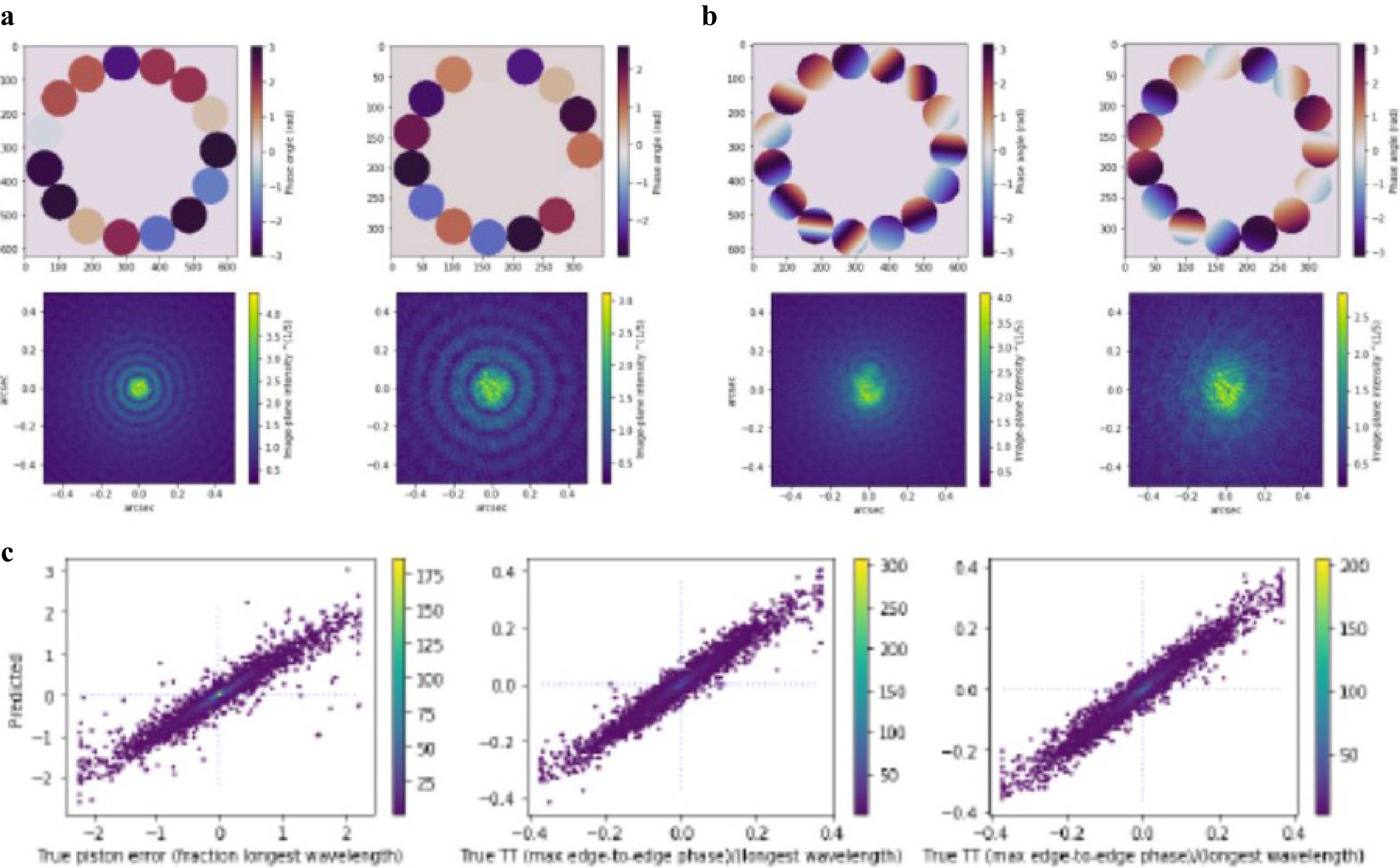
Fig. 16 a A prototype 15 x 0.5m Fizeau telescope has been simulated with atmospheric phase screens in order to train a convolutional neural network to obtain piston corrections of the mirror segments. This image shows how piston errors affect mirror speckles. b Similarly tip/tilt errors are distinct in the images. c Training a convolutional neural network with 105 images yields a system that not only reproduces atmospheric p/t/t errors but also yields phase wrap solutions over more than 5 wavelengths of phase errors from 10% bandwidth speckle images. Lower plots show predicted piston and true phase and phase gradients
The current machine learning solution is based on a supervised learning approach. A dataset for training the model was generated for a central wavelength of 1.55 μm allowing a variation range for the piston up to 1 μm. The model consisted of a stack of variable number of 2D convolutional layers, each utilizing Rectified Linear Unit (ReLU) activation functions, followed by one or more dense layers at the output. The Strehl ratio of the PSF, defined as the ratio between the maximum intensity of the aberrated image and the perfect image, is employed to assess the performance of the system. After training, the optimal correction is provided. An illustrative example is shown in Fig. 17. In this case the model was trained for 50 epochs using the RMSE losses and the ADAM optimizer49 with a learning rate set to $ 10^{-3} $. Only 5000 simulations for a monolayer atmosphere with a 0.25 m Fried parameter, splitted 80/20% for train and test, were considered. That explains the modest improvement observed for the Strehl ratio.
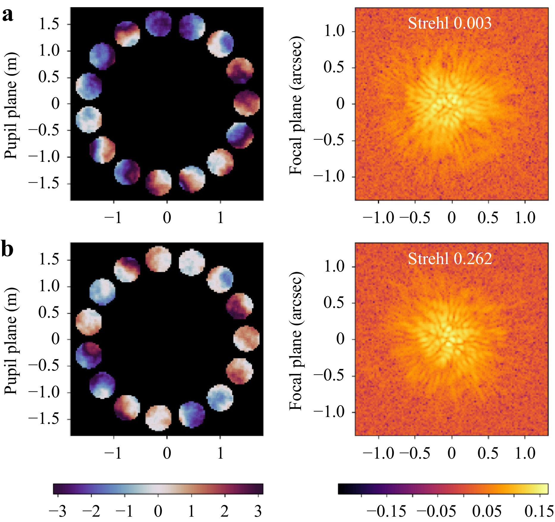
Fig. 17 a Pupil phase distribution (or OPD) and focal plane PSF (or image) for a telescope simulation in which a monolayer atmosphere with a 0.25 m Fried parameter was considered. b Corresponding Pupil phase distribution and focal plane PSF after the correction provided by the supervised machine learning approach. The improvement on the Strehl radius can be observed. Note that the algorithm was trained with only 5000 simulations.
Furthermore, in combination with the machine learning approach, a photonic lantern is being tested as a promising technology for addressing the cophasing procedure. A photonic lantern consist of a tapered waveguide that transitions from a few-mode optical fiber to multiple single-mode fibers enabling efficient coupling of aberrated telescope light into single-mode fibers. To implement this approach, our laboratory “nanoELF” model was simulated considering commercial 2-inch spherical mirrors as apertures using HCIPy. The two sub-apertures were spaced 120 mm apart (center-to-center) having a focal length of 1016 mm. In addition, a standard six core photonic lantern was simulated using the Lightbeam package50 in Python. In this case, for the supervised machine learning approach, the computed intensities of the single-mode fibers were used as input to train several machine learning algorithms. The outputs of the system provide the optimal PTT adjustments of the apertures. Further details regarding the implementation of this approach can be found in Padrón-Brito et al.51.
-
The SELF goal is to maintain phase control of the subapertures at the level of 0.01 radians (or about 60nm) in order to create $ 10^{-4} $ dark holes in the PSF within $ \lambda/D $ (Fig. 6). This requires high order adaptive optics. Fig. 7 shows schematically how the secondary AO system receives cophased light from the telescope M1-M2 active optics. The AO system is based on the Lyon-group Mach-Zehnder system and is described in Graf et al.52.
-
A first cut at a block diagram for the control elements of SELF is illustrated Fig. 18. The 15 subapertures and precision active controls of the two mirrors in each subaperture define a complex system with about 160 DOF. These are determined by as many optical parameter outputs from the phase and atmospheric cameras and spatial encoders on the actuators. This opto-mechanical system is an excellent candidate to be controlled with a supervised machine learning model.
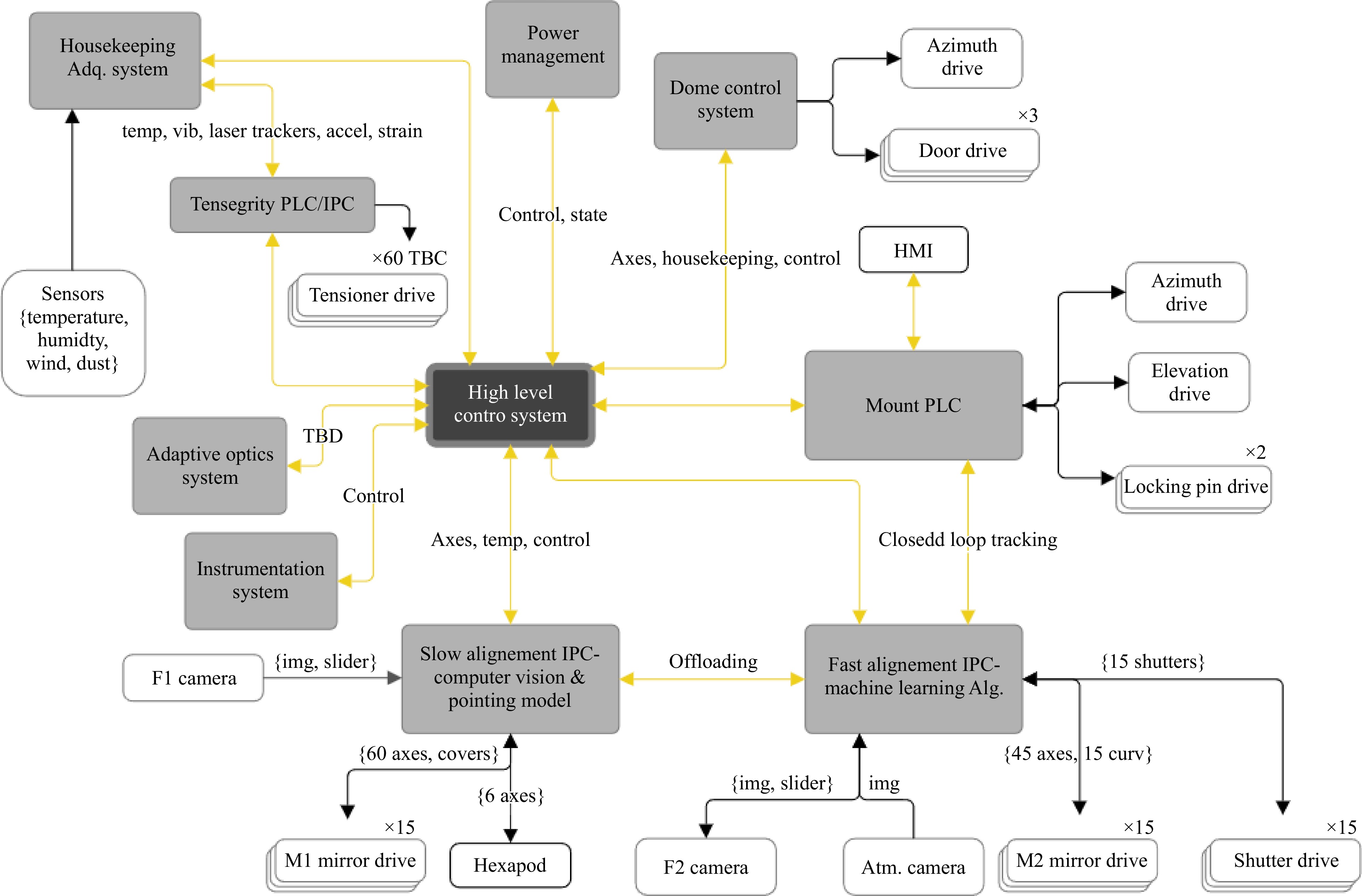
Fig. 18 Control System Layout of SELF.
-
A fascinating question, triggered by our rapidly expanding understanding that life- and water- bearing planets around other stars could be common, Ref. 53 is “Can we learn fundamentals about life on Earth by studying other planets?” Most astronomers have relegated this problem to NASA or ESA and future generations but this is a question that may sooner be tackled from the ground. It requires a large and dedicated telescope that uses emerging technologies like machine learning and additive manufacturing. The Fizeau interferometer we propose here will push our abilities to create large, stiff, low mass optical structures and to control these systems of many degrees of freedom rapidly to overcome the atmosphere. The SELF pathfinder telescope illustrated in Fig. 19 is now under construction and will provide confidence that this is feasible. We believe, as we argued here, that there are no fundamental reasons why we cannot build 50 m-scale telescopes on the ground that can reach sensitivity levels sufficient to find evidence of life on nearby exoplanets.
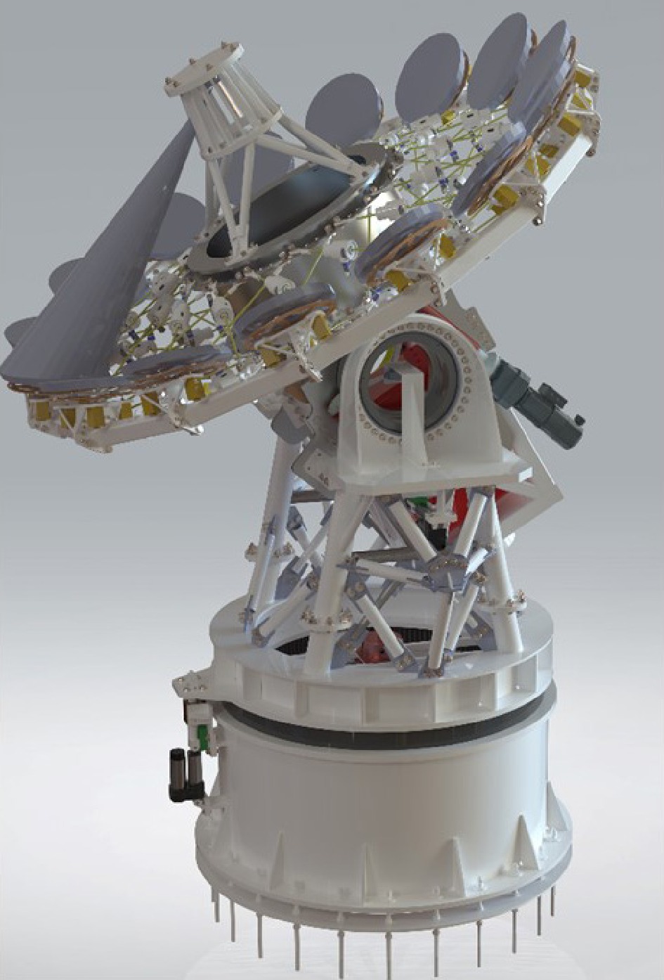
Fig. 19 The SELF telescope is under construction at Teide Observatory on Tenerife in the Canary Islands (Spain)
-
We’re grateful for the continued support of other members of the LIOM advisory committee: Andres Asencio-Ramos (IAC, Spain), Justin Fletcher (Odyssey Systems, USA), Pradip Gatkine (UCLA, USA), Stuart Jefferies (GSU, USA), Wolfgang Osten (ITO, Germany), Sudhakar Prasad (University of Minnesota, USA), S. Peter Worden (Breakthrough Foundation) and Ryan Swindle (Odyssey Systems, USA). Our LIOM internship students: Roxanna de Alba (Dallas College, USA), Jade Barrett (Institut d’Optique Université Paris-Saclay, FR), Théophile Boillot (Ecole Nationale Supérieure de Techniques Avancées, ENSTA Paris, FR), Savannah van Proosdij (Stichting Leidse instrumentmakers School, Leiden, NL), Manon Le Teuff (Université Paris Sciences et Lettres, FR) have each made important contributions to this research and engineering program. The authors acknowledge funding from the European Union, Project Ref.: 101087032. Views and opinions expressed are however those of the authors only and do not necessarily reflect those of the EU or the EU Research Executive Agency. Neither the European Union nor the granting authority can be held responsible for them. LIOM project’s R&D&i activities are also supported by the Cabildo Insular de Tenerife thanks to the “Apoyo a las actuaciones I+D+I en el espacio de cooperación IACTEC” collaboration agreement. NL acknowledges support from the Agencia Estatal de Investigación del Ministerio de Ciencia e Innovación (AEI-MCINN) under grants PID2019-109522GB-C53 and PID2022-137241NB-C41.
Creating ground-based telescopes for imaging interferometry: SELF and ELF
- Light: Advanced Manufacturing , Article number: (2025)
- Received: 29 September 2024
- Revised: 12 March 2025
- Accepted: 25 March 2025 Published online: 10 July 2025
doi: https://doi.org/10.37188/lam.2025.033
Abstract: The largest ground-based telescopes will be much larger than their space-based counterparts far into the future. Remote sensing problems that can take advantage of active and adaptive wavefront control that correct the incoming atmospherically distorted optical wavefront can benefit from very large ground-based telescopes that have other important advantages. For example, their much lower cost (typically one or two orders of magnitude less) and shorter time-to-completion can be compelling. For optical or IR problems that require high angular resolution and large photometric dynamic range we suggest that techniques that make use of photonics, machine learning, or additive manufacturing may even enable less expensive specialized telescopes that are larger than what astronomers are currently building. The Instituto de Astrofísica de Canarias (IAC) recently began a 5 year program with support from the European Union called the Laboratory for Innovation in Opto-mechanics. Its goal is to show how technology innovations can enable less costly and larger telescopes, in particular, aimed at the problem of finding extrasolar life within a few parsecs of the Sun.
Rights and permissions
Open Access This article is licensed under a Creative Commons Attribution 4.0 International License, which permits use, sharing, adaptation, distribution and reproduction in any medium or format, as long as you give appropriate credit to the original author(s) and the source, provide a link to the Creative Commons license, and indicate if changes were made. The images or other third party material in this article are included in the article′s Creative Commons license, unless indicated otherwise in a credit line to the material. If material is not included in the article′s Creative Commons license and your intended use is not permitted by statutory regulation or exceeds the permitted use, you will need to obtain permission directly from the copyright holder. To view a copy of this license, visit http://creativecommons.org/licenses/by/4.0/.

 DownLoad: