


-
KHxD2-xPO4 crystal optics with high manufacturing accuracy and laser damage resistance are the key to improving output energies of high-energy/power laser facilities (e.g. National Ignition Facility (NIF) in the United States, Laser Megajoule Facility in France1–4). The NIF, the most representative of these laser facilities, is equipped with 192 beamlines and could output a 1.8 MJ, 500 TW ultraviolet laser in a few nanoseconds, representing the greatest advancement thus far in laser-driven inertial confinement fusion. The NIF houses 7648 large-aperture (meter-sized) optics5. These optics, particularly the terminal KHxD2-xPO4 optics, would be exposed to ~10 kJ ultraviolet lasers. However, the manufacturing processes of KHxD2-xPO4 optics would introduce laser damage precursors, such as micro-scratches, cracks, and debris. These laser damage precursors would be detonated by the ultraviolet laser and spark off the laser-induced surface damages and damage growth, which have been the bottleneck problems of the high-energy/power laser facility. To guarantee the functions (frequency conversion, electro-optic switch, etc.) of KHxD2-xPO4 optics, the laser damage precursors need to be strictly controlled and limited under the nm-level geometric accuracies, as shown in Table 1. Additionally, it takes more than two years to grow one meter-sized KHxD2-xPO4 crystal boule via the traditional cooling method, and with its soft-brittle, easily deliquescent, anisotropic, and temperature-sensitive nature, KHxD2-xPO4 can be a difficult-to-cut material and yields great challenges for ultra-precision manufacturing6. The high-accuracy, low-defect manufacturing for regulating laser damage precursors in KHxD2-xPO4 optics could indicate the level of the optical manufacturing techniques required for this material owing to its difficult-to-cut nature.
Measured band Spatial scale length (mm) Spatial frequency (1/mm) Parameter Value b Band 1 400 to 33 2.5 × 10⁻³ to 3.0 × 10⁻² rms c gradient (nm/cm) 11 Band 2 (PSD-1) 1 33 to 2.5 3.0 × 10⁻² to 0.4 rms waviness (nm) 5 A (nm2/mm−1) 15 Band 3 (PSD-2) 2.5 to 0.12 0.4 to 8.3 rms waviness (nm) 2.6 pk (1.5 avg.) A (nm2/mm−1) 15 Band 4 0.12 to 0.01 8.3 to 100 rms roughness (nm) 2.5 pk (1.5 avg.) a: PSD = power spectral density. b: all values are for λ = 633 nm. pk: peak; avg.: average. c: rms = root mean square. Adapted with permission50. Copyright 2004, Society of Photo-Optical Instrumentation Engineers. Table 1. Manufacturing requirements for KHxD2-xPO4 optics.
As mentioned earlier, laser damage precursors, which would violently absorb the laser energy when irradiated by an intense laser pulse, in optics are the root cause of laser-induced surface damage and damage growth. Nevertheless, the ultraviolet photon energy of a triple frequency laser (with a wavelength of 351 nm) is only 3.53 eV, whereas the band gap of KHxD2-xPO4 is higher than 7.8 eV, and thus, the laser energy could be hardly absorbed7. However, in practice, the average laser-induced damage threshold (LIDT) of manufactured KHxD2-xPO4 optics is approximately 8.7 J/cm2 (351 nm, 3 ns), which is much lower than the theoretical value (147–200 J/cm2)8–10. KHxD2-xPO4 optics with high laser performance are beneficial for improving the output energies of the high-energy/power laser facilities. For example, the routine ultraviolet fluence of the NIF should be lower than 4 J/cm2 to avoid laser-induced surface damage and damage growth, and thus, to deliver higher energies, the ‘five loop’ strategy is proposed11. For this strategy to work, the key is to regulate the laser damage precursors (specifically, inhibiting the surface/subsurface defects (SSDs) and repairing laser-induced surface damage). With this strategy, the NIF could stably output ultraviolet laser energies greater more than 1.8 MJ, 500 TW. Thus far, the NIF has already generated 5.2 MJ fusion energy by delivering 2.2 MJ ultraviolet laser energy to a target, fulfilling its ignition goal, and thus, to achieve a new level of fusion ignition in the future, a higher ignition energy (3.0 MJ) is proposed12,13. To accomplish these targets, the development of optics without laser damage precursors (i.e. high laser damage resistance, LIDT > 10 J/cm2) is urgently pursued. At present, low LIDTs are a technical bottleneck that has limited the development of the high-energy/power laser facilities. It is vital to regulate laser damage precursors via advanced optical manufacturing techniques to avoid laser-induced surface damages and damage growth, as summarised in Fig. 1. These techniques could process the optical surface in a point-to-point manner to locally remove laser damage precursors. Besides, all the laser damage precursors could also be removed at once by removing a layer of the KHxD2-xPO4 substrate material. However, there are still some problems in the batch engineering application of these techniques, such as the meter-sized apertures of the optics and their soft-brittle, easy-deliquescent, anisotropic, and temperature-sensitive material properties. And the LIDTs of KHxD2-xPO4 optics are still much lower than the theoretical thresholds in practice, which indicates that there remain numerous residual laser damage precursors that could not be identified and removed. Each technique might also introduce new laser damage precursors, limiting the improvement of the laser damage resistance of the optics. The laboratory conditions are also different from working conditions, e.g. in terms of the sample size and beam size. Additionally, the stronger laser pulses pursued by high-energy/power laser facilities bring new challenges to the service performance of the optics. It is widely accepted that improving the LIDTs of KHxD2-xPO4 optics is an urgent engineering problem that remains to be solved. Nevertheless, current techniques for regulating the laser damage precursor in KHxD2-xPO4 optics have reached a technical bottleneck, preventing further improvement in optics’ LIDTs. A comprehensive review of underlying principles, challenges, viable solutions, and future development trends in these regulation techniques could provide valuable insights and guidance for further improving the LIDTs of KHxD2-xPO4 optics and achieving function-driven high-performance manufacturing.
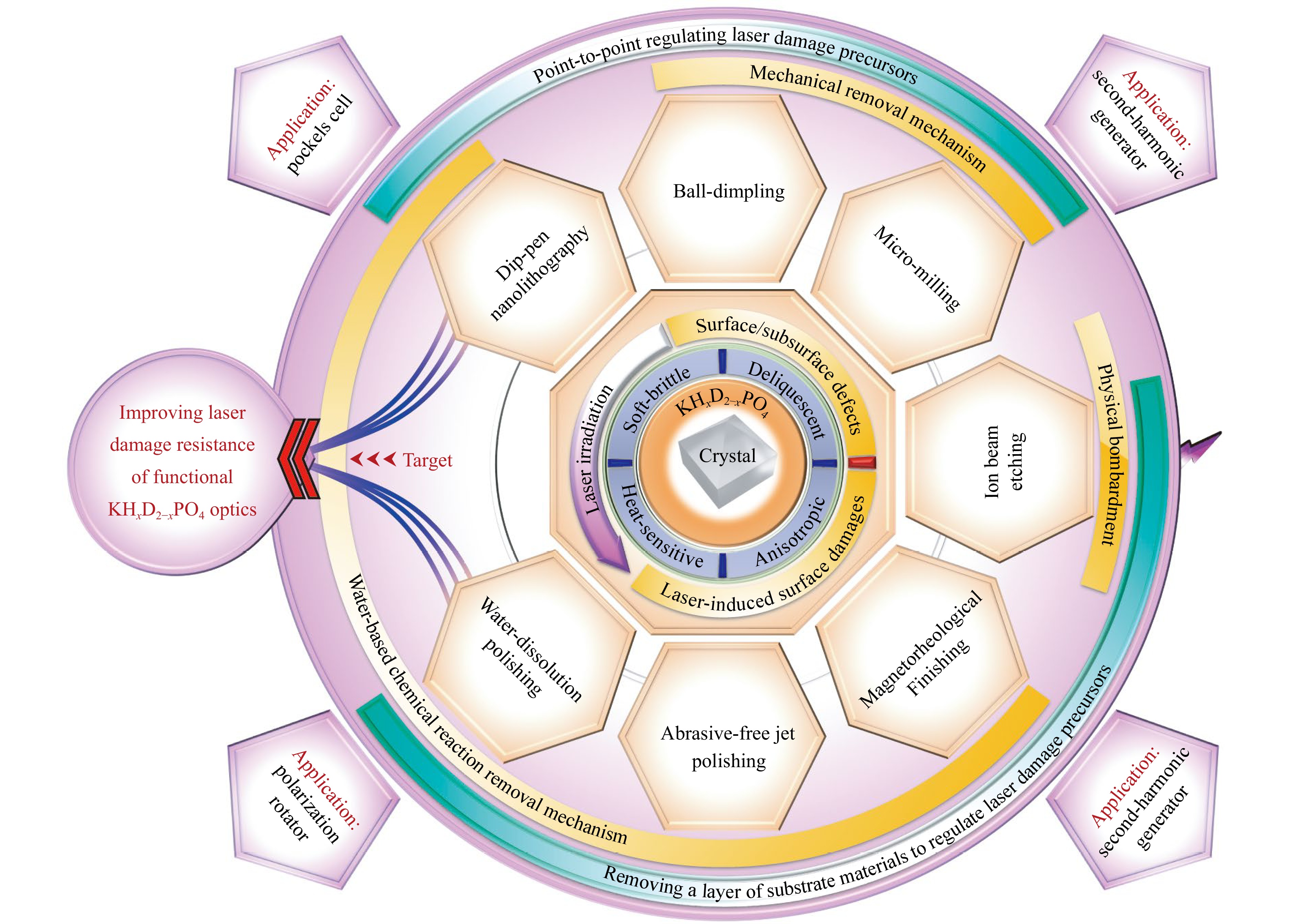
Fig. 1 Summary of the advanced manufacturing techniques used to regulate laser damage precursors (surface/subsurface defects (SSDs) and laser-induced surface damage) in KHxD2-xPO4 optics. The key material removal mechanisms of these techniques are also summarised together with the main material properties and applications of KHxD2-xPO4 crystals.
In this article, we first review the intrinsic physical mechanism of laser-induced surface damage initiation and growth and discuss hazards of laser damage precursors in optics. Then, the functions and manufacturing requirements of KHxD2-xPO4 optics are summarised. Afterwards, the current development statuses of the optical manufacturing techniques listed in Fig. 1 are reviewed, and the problems of the manufacturing processes and their corresponding solutions are systematically compared, analysed, and summarised. Finally, the future development trends and challenges regarding KHxD2-xPO4 optics are discussed in depth. This work could provide basis and guidance for improving the service performance of optics made from soft-brittle and deliquescent materials, advancing the development of high-energy/power laser facilities, and applying these optical manufacturing techniques in actual engineering practice.
-
Elucidating the intrinsic mechanism of laser-induced surface damage and damage growth is of great significance to regulating laser damage precursors in optics. First, it allows the relationship between laser damage precursors and laser damage to be mapped, thus providing basis and guidance for adopting appropriate manufacturing techniques and formulating corresponding regulation strategies. Second, it provides a criterion for evaluating the improvement effects on the laser damage resistance of optics. Moreover, rapid laser-induced surface damage growth would greatly reduce the service life of optics, and therefore, it is vital to determine appropriate repair times and formulate the best repair strategies for the optics.
-
Laser damage precursors (e.g. manufacturing-induced micro-cracks, scratches, and debris) are the root cause of laser-induced surface damage initiations, and therefore, the most hazardous of them must be effectively inhibited to improve the laser damage resistance of optics14–16. Essentially, laser-induced surface damages are the result of material modification caused by strong laser energy deposition, with peak temperatures that could reach or even exceed 12000 K when damage occurs17. Laser-induced damage mechanisms can be categorised into extrinsic and intrinsic mechanisms, as shown in Fig. 218–20. Extrinsic mechanisms, which are also known as inclusion-initiated thermal explosion mechanisms, are induced mainly by foreign absorptive impurities inside the optics21,22. The impurities would absorb laser energy and heat vicinal materials, resulting in high local temperatures. The elevated temperatures would induce local modifications and band gap collapse in the optical material, which further leads to sub-band gap intrinsic absorption of the incident laser. As the optical material’s absorption of the incident laser becomes uncontrollable, a high-temperature and high-pressure plasma ball would be formed inside the optics. Ultimately, this plasma ball would explode, causing material stripping and sputtering and mechanical impact damage. On the other hand, intrinsic damage mechanisms are induced by strong field ionization, which involves mainly the nonlinear excitation process of bound electrons apart from foreign absorptive impurities18,23. The intrinsic damage mechanisms could be divided into two stages, non-heat stage and thermal stage. First, at the non-heat stage, intense laser irradiation would induce electric dissociation and generate high-energy plasma. The free electron density in the optics would increase through the nonlinear photoelectric effects such as photoionisation and avalanche ionisation, forming plasma waves in the surface24. When the free electron density increases to a critical value, the dielectric material would have metal-like properties, and the plasma wave would resonate with the incident laser. Then, the laser energy would be absorbed violently through reverse bremsstrahlung, eventually leading to ablation damage25. Subsequently, at the thermal stage, thermal diffusion and heat melting in the ablation zone would lead to formation of craters and cracks on the optical surface, as well as particle ejection, shock wave propagation, and other dynamic behaviours, which would result in catastrophic laser damages to the optics26.
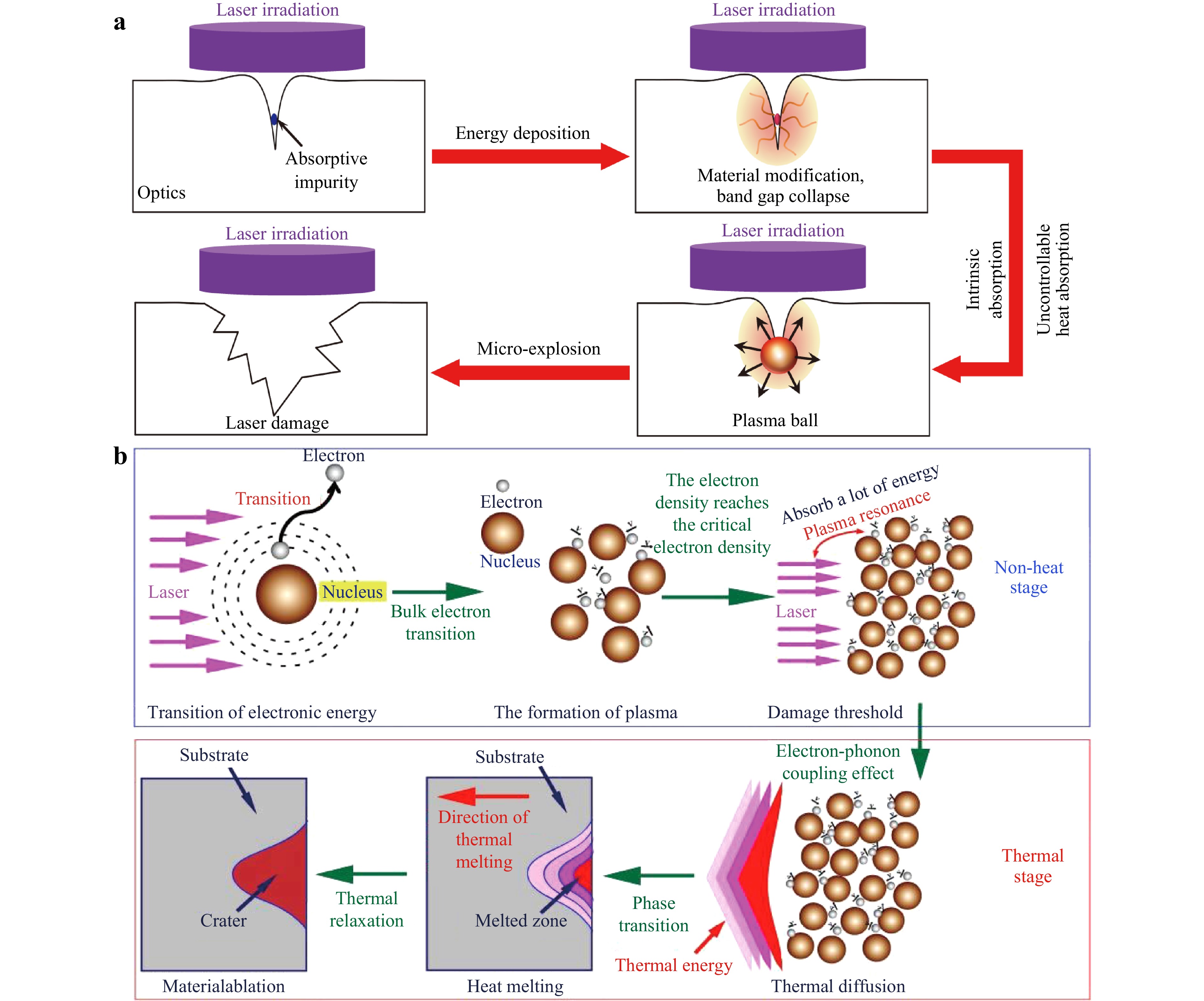
Fig. 2 a Schematic of extrinsic damage mechanism caused by absorptive impurity. b Schematic of intrinsic damage mechanism caused by strong field ionisation. Reproduced with permission20. Copyright 2021, Society of Photo-Optical Instrumentation Engineers.
Although the extrinsic and intrinsic damage mechanisms have different physical natures, in the early stage of laser irradiation, both mechanisms involve intense absorption of laser energy by the laser damage precursors and the excitation of plasma17. There are many types of laser damage precursors known to cause laser-induced surface damage, such as mechanical defects (micro-cracks, micro-pits, tool marks, etc.), impurities (Al, Ba, S, etc.), and chemical structural defects (O vacancy, H vacancy, etc.)15,27–32. Impurities would result in extrinsic damages, whereas chemical structural defects would lead to sub-band gap absorption of the incident laser. Mechanical defects would reduce laser damage resistance via the following mechanisms: (a) the incident laser is modulated, resulting in local field enhancement; (b) foreign impurities wrapped inside the defects absorb the laser energy; (c) the mechanical strength is reduced, making the optics more vulnerable under thermal stress; (d) the material is more likely to be ionised because of chemical structure defects that accompany the micro-fractures. Meanwhile, particle contaminants bound to the surface of the optics, particularly opaque particles on the front surface and transparent particles on the rear surface, would spark off laser-induced surface damage. These contaminants would cause catastrophic damage with an abundance of fracturing and a high ease of to growing into even more extensive damage33–35. It is very important to eliminate these laser damage precursors to avoid the initiation of laser-induced surface damage. In addition, the hazards of laser damage precursors are related to the laser irradiation conditions. With the improvement of the output laser energies of the high-energy/power laser facilities, laser damage precursors thought to be relatively harmless might lead to severe laser-induced surface damage when subjected to higher-fluence lasers. Identifying new laser damage precursors and removing them by developing corresponding optical manufacturing techniques is thus an ongoing process.
-
Although optics could be refinished to remove all laser-induced surface damage at once, it is not advisable in practice because this method is time-consuming and costly and may introduce new SSDs. Moreover, optics could be refinished only a few times to maintain its complete function, e.g. third-harmonic generator optics could be refinished only approximately 2 or 3 times for efficient frequency conversion36. A laser-friendly contour is preferred to locally replace laser-induced surface damages. Currently, in the ‘five loop’ strategy, laser-induced surface damages are monitored in situ and repaired when their sizes reach 20 to 300 μm7,37.
Numerous laser damage precursors (e.g. laser-induced material modification, explosion-induced micro-cracks) would be generated inside the laser-induced surface damage sites, which would violently absorb laser energy and should be accounted for as a primary cause of rapid damage growth38–40. Typical laser-induced damage growth behaviours on the optical surfaces are shown in Fig. 3. Fundamentally, the growth behaviours of laser-induced damage sites on the optical surfaces represent the re-damage processes driven by interactions between the laser damage precursors within the initial damage sites and the incident laser41. By absorbing laser energy, these laser damage precursors would generate plasmas that would be concentrated mainly in the core and edge of the laser-induced surface damage sites, as shown in Fig. 3. The edge of the initial laser-induced damage site exhibits a higher plasma generation threshold compared to the inner core region. As shown in Fig. 3b, c, some sporadic plasma initiation sites appear at the edge slightly later than those in the inner core region. However, these edge plasma initiation sites are closely associated with the lateral extension of the laser-induced damage morphology, as illustrated in Fig. 3c, d. In contrast, the inner core region, which contains a higher concentration of the laser damage precursors, would strongly absorb laser energy, leading to the formation of the high-density plasma initiation sites. The laser energy deposited in the inner core region ultimately determines the number and size of subsequent crack formations, as depicted in Fig. 3f, g. Even after the laser irradiation ceases, the crack formation and expansion could persist for tens of nanoseconds, culminating in an explosion that causes material sputtering lasting tens of microseconds. Notably, there are strong correlations between the circumferential cracks and the final contour of the laser-induced damage site. Higher amounts of energy would be deposited in the core during laser irradiations with longer pulse durations, consequently resulting in more serious crack formation and propagation. Therefore, laser-induced surface damage sites irradiated by longer-duration pulses grow faster than those irradiated by shorter-duration pulses. The transverse sizes of laser-induced surface damages on the front and rear surfaces of KHxD2-xPO4 optics both grow linearly, with growth rates that are approximately linear with the energy density of the incident laser42. Furthermore, the rear surfaces of optics are more susceptible to laser-induced surface damages compared to the front surfaces, and thus, current research studies have focused mainly on laser-induced surface damage growth on the rear surfaces of optics7,42. Laser-induced surface damage on a rear surface grows faster, and numerous micro-fractures exist on the edge and below these laser-induced surface damage sites. The propagation of micro-fractures is the main feature of rapid damage growth43. The laws governing laser-induced surface damage growth on KHxD2-xPO4 optics are complex, and an exponential growth mode has been observed7. If the remaining materials were large, strong, and firmly attached to the bottom of the laser-induced surface damage sites, the relaxation of their stress could result in cracking of the underlying KHxD2-xPO4 material, which also signifies that crack propagation is the root cause of the exponential growth law. The laws governing the growth in damage depth, especially the crack propagation depth, and the aspect ratios of the laser-induced surface damages are important for formulating strategies to avoid incomplete repair. Therefore, it is very important to eliminate these micro-cracks to avoid rapid laser-induced surface damage growth.
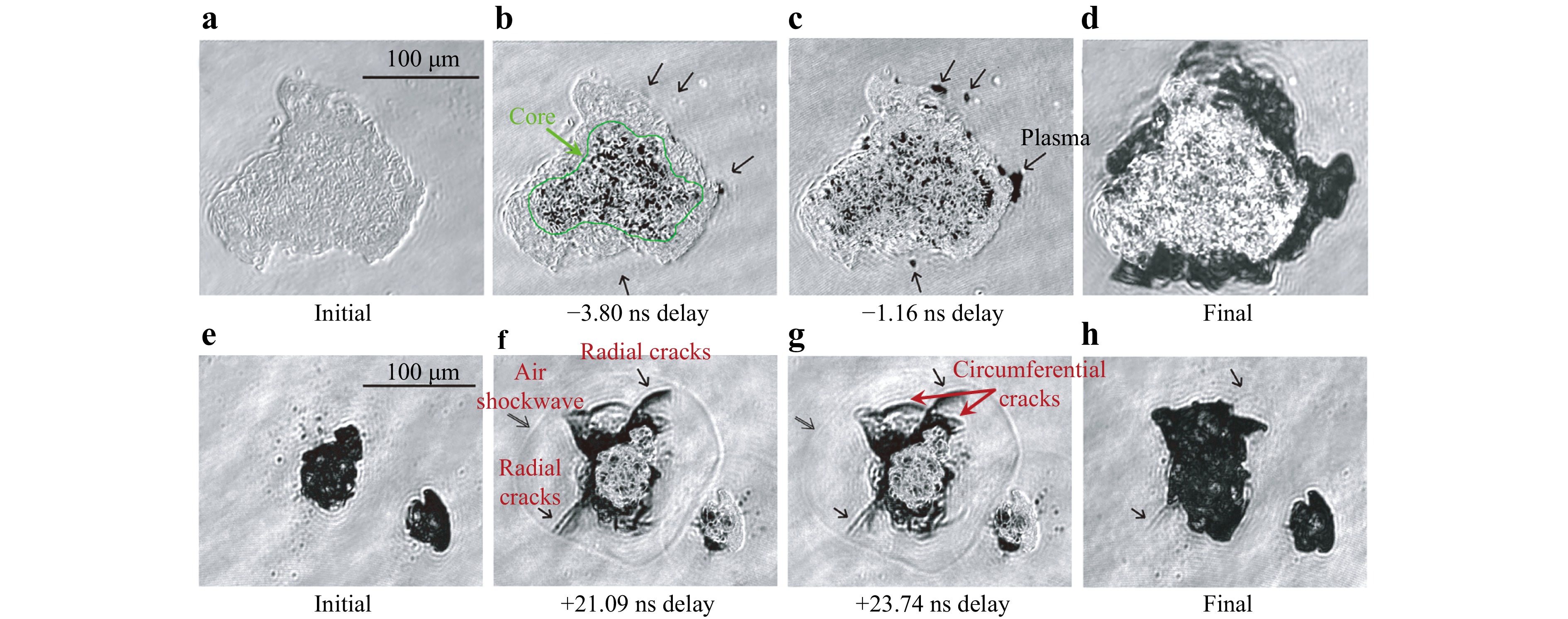
Fig. 3 Experimental observations of the growth processes of the typical laser-induced surface damage sites with −3.80 ns, −1.16 ns delay a-d, and +21.09 ns, +23.74 ns e-h. Adapted with permission44. Copyright 2013, Optical Society of America.
In summary, the initiation and growth of laser-induced surface damage are sparked off by the interaction between laser damage precursors and strong laser pulse. Eliminating the laser damage precursors through advanced optical manufacturing techniques is effective for improving the laser damage resistance of KHxD2-xPO4 optics.
-
The KHxD2-xPO4 crystal has excellent nonlinear optical and electro-optical properties and is transparent over a wide region of the optical spectrum. Furthermore, it could convert a 1ω infrared laser into a 2ω green laser and 3ω ultraviolet laser. In high-energy/power laser facilities, KHxD2-xPO4 crystals are used to fabricate the plasma electrode Pockels cell, polarisation rotators, second-harmonic generators, and third-harmonic generators, of which only the third-harmonic generator would be irradiated by ultraviolet lasers5,45.
The KHxD2-xPO4 crystal could grow to the large sizes (55 × 55 × 55 cm) required by high-energy/power laser facilities; however it is also well known among researchers around the world as a difficult-to-cut material owing to its soft-brittle properties, easy cracking, deliquescence, sensitivity to temperature changes, and strong anisotropy46,47. A comparison between the orientations of manufactured KHxD2-xPO4 optics and their parent single-crystal boule is shown in Fig. 4a5. The finishing quality required for the KHxD2-xPO4 optics is shown in Table 1, and the geometric accuracy needs to be maintained at under nm-level full-band spatial errors. In present engineering practice, single-point diamond turning is the main ultra-precision manufacturing method used for KHxD2-xPO4 crystals, as shown in Fig. 4b, c48. However, without sufficient optimisation, there might be some micro-cracks, micro-pits, nodules, scratches, tool marks, ripples, etc., on the surface and sub-surface of the optics after the single-point diamond turning, resulting in diffraction effects and stray light27,48,49. Fig. 4d illustrates the typical defects and textures in KHxD2-xPO4 optics. During laser irradiation, these SSDs would cause severe laser-induced surface damage, which would then grow in subsequent laser shots. The laser conditioning would also detonate any weak points in advance, resulting in an initial laser-induced surface damage, which should be repaired prior to installation. Another aspect to consider is that the growth rate of the KHxD2-xPO4 crystal when manufactured via the traditional cooling method is approximately 1.5 mm/day. However, to manufacture large-aperture optics, large-size single-crystal boules are required, as shown in Fig. 4a, which in turn increases the operating costs. To manufacture KHxD2-xPO4 crystal optics with high laser damage resistance, it is highly essential to inhibit the formation of SSDs and repair any laser-induced surface damages that had formed on the optics.
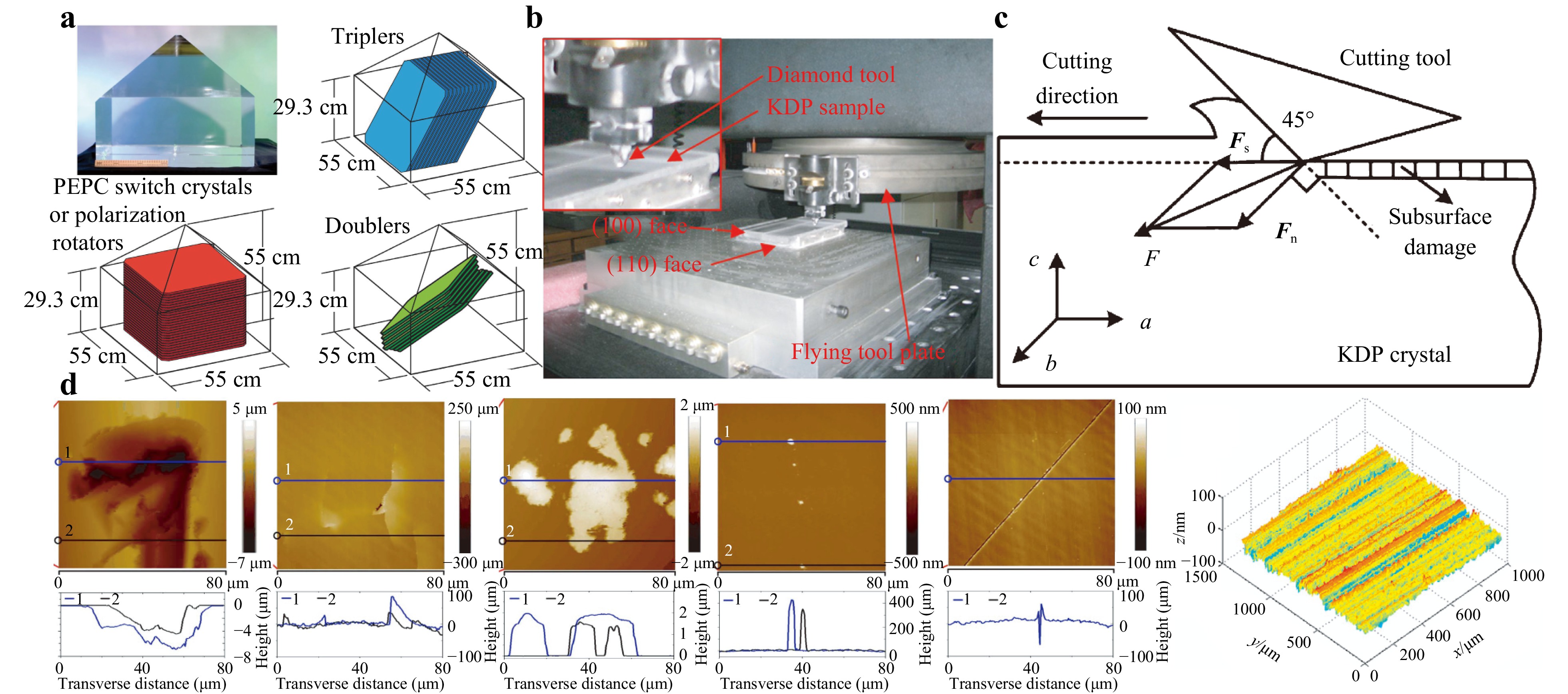
Fig. 4 a Relation between crystal optics and single-crystal boule. Reproduced with permission5. Copyright 2017, Taylor & Francis Group. b, c Single-point diamond turning process for KHxD2-xPO4 optic. Reproduced with permission48. Copyright 2013, Elsevier. Reproduced with permission46. Copyright 2019, Springer Nature. d Images of fracture pits, cracks, surface protuberances, convex scratches, plastic scratches, and surface texture (from left to right) on surfaces of KHxD2-xPO4 optics. Adapted with permission27. Copyright 2018, Optical Society of America. Adapted with permission48. Copyright 2013, Elsevier.
-
SSDs (e.g. scratches, cracks, pits, nodules) are the root cause of laser-induced surface damage. Therefore, in the manufacturing stage, prior to installation, ‘near-perfect’ KHxD2-xPO4 optics without SSDs are pursued via the use of appropriate optical manufacturing techniques. It is uneconomical and impractical to repair optics with many SSDs using point-to-point manufacturing techniques. At present, full-aperture optical manufacturing techniques, which involve weaker mechanical actions and are conducive to removing all SSDs at once, are being developed to regulate SSDs in KHxD2-xPO4 optics. These techniques mainly encompass water-dissolution polishing (WDP), abrasive-free jet polishing (AFJP), magnetorheological finishing (MRF), and ion beam etching (IBE).
-
The soft-brittle and deliquescent nature of KHxD2-xPO4 poses great challenges to the manufacturing process. At 25 °C, the solubility of KHxD2-xPO4 in water is as high as 33 g/100 g51. When processed by traditional chemical mechanical polishing, the surfaces of the KHxD2-xPO4 optics would be damaged by the water and abrasive particles in the polishing slurries. However, if the water were to be used as the abrasive particles and the deliquescence processes could be controlled, the ultra-precision polishing of KHxD2-xPO4 optics, i.e. WDP, could be achieved. WDP has two material removal mechanisms: dissolution removal by the water and mechanical scraping removal by a polishing pad under pressure, of which water-dissolution removal is the dominant mechanism. As shown in Fig. 5a, under centrifugal force, the slurry is evenly distributed on the polishing pad and forms a film between the pad and KHxD2-xPO4 optic, with which the optic could then be processed using the polishing pressure52.
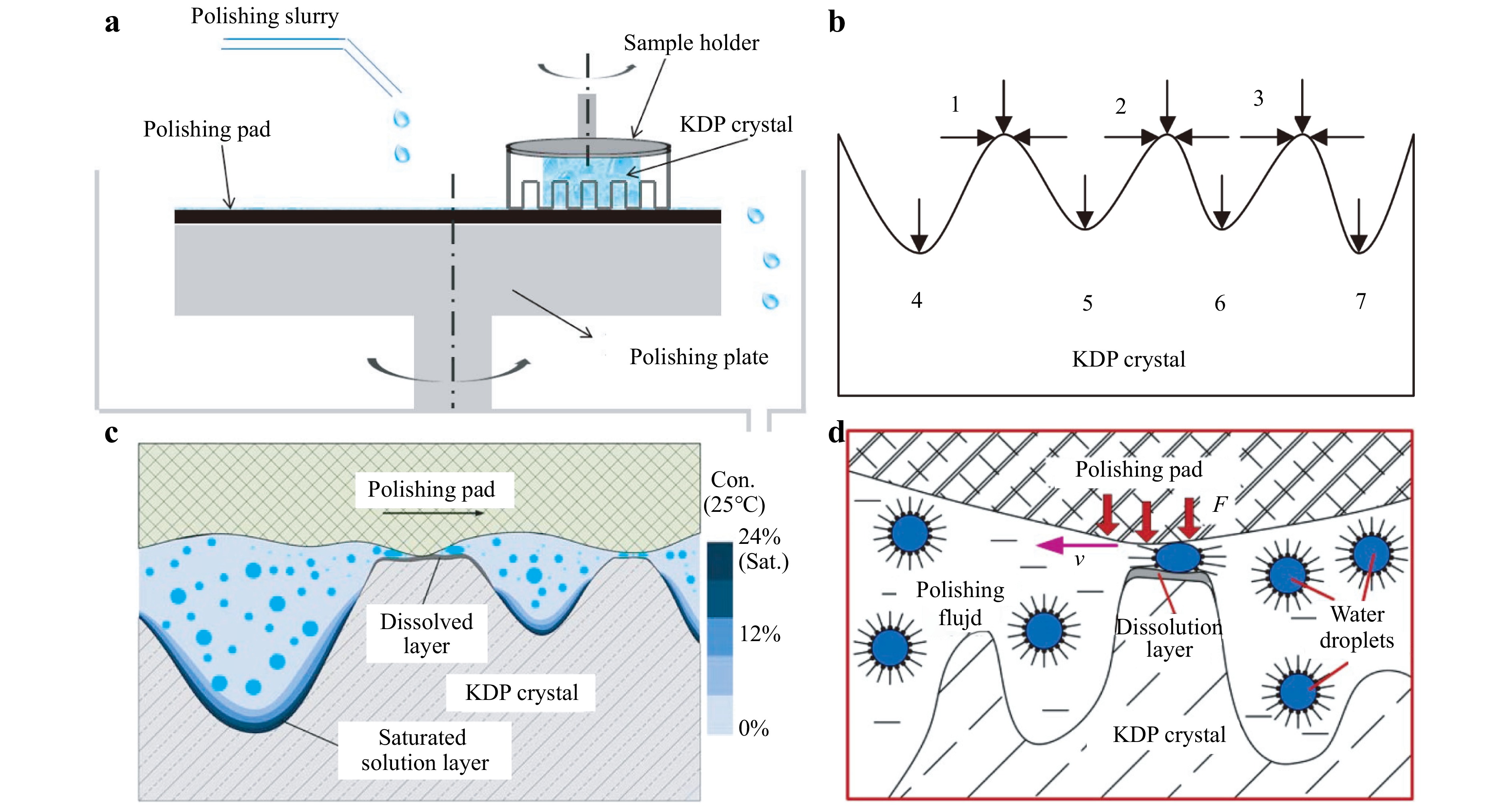
Fig. 5 a Schematic diagram of typical WDP process for the manufacture of KHxD2-xPO4 optics. Reproduced with permission52. Copyright 2017, MDPI. b–d Schematic of dissolution removal mechanisms of different polishing slurries: b water, alcohol, surfactant, Reproduced with permission54. Copyright 2009, Trans Tech Publications. c micro-water mist or unsaturated KHxD2-xPO4 solution, Reproduced with permission53. Copyright 2015, Inderscience Enterprises. d microemulsion, Reproduced with permission55. Copyright 2020, Elsevier.
The key to effective WDP is to design the slurries appropriately, as summarised in Table 2. When the slurry base is dehydrated ethanol, only the mechanical scraping removal mechanism exists; the material removal rate is low, and the surface quality is poor. Moreover, the polished surface would absorb moisture and form a saturated solution in the form of drops, resulting in numerous corrosion pits56. When the slurry base is deionised water, the processing efficiency is greatly improved because of the dissolution removal mechanism; however, the surface quality would still be unable to meet the requirements. Even if unsaturated KHxD2-xPO4 solution or micro-water mist were to be used as the slurry base to increase the control over the deliquescence process, it would still be difficult to obtain a high surface quality53,57,58. When the slurry base is composed of water, alcohol, and surfactant, a polished surface with arithmetical mean roughness (Ra) 2.950 nm could be obtained; however, the alcohol is volatile59. When the slurry base is a microemulsion, a high-quality surface with rms roughness lower than 2 nm could be obtained; however, to maintain the stability of the microemulsion, the water content should be strictly controlled, resulting in low processing efficiency51,60,61. The water content would also change the wetting characteristics of the microemulsion and have great influence on the surface quality62. Replacing the water in the microemulsion with a KHxD2-xPO4 solution could further improve surface roughness and prevent the formation of corrosion pits, but the efficiency would be reduced52. However, it should be noted that numerous organic contaminants would be left on the surface, which should be cleaned up using volatile-compatible organic solvent, e.g. toluene63. Overall, for KHxD2-xPO4 manufacturing via WDP, high efficiency and high surface quality are always contradictory. Nevertheless, a novel water dissolution combined continuous polishing technique has recently been proposed for high-efficiency, high-quality processing of KHxD2-xPO4 optics64. This technique comprises three key procedures: precision polishing using an aqueous solution, ultra-precision polishing with water-in-oil microemulsion, and final cleaning with anhydrous ethanol. And a 180 mm × 180 mm KHxD2-xPO4 optic with the PV of 1.938 wave and the rms of 0.264 wave could be obtained through this water dissolution combined continuous polishing technique.
Polishing slurry Composition Water-soluble Deionised water or dehydrated ethanol56 Water, alcohol, surfactant54,59 Micro-water mist53, 57, 58, 65 Unsaturated crystal growth solution66 Water-in-oil microemulsion Water, dodecanol, and Triton X-10051, 55, 60, 62, 63, 67−71 Decanol, Triton X-100, and crystal solution52 Cyclohexane, water, Triton X-100, and hexanol72,73 Methyltrioctylammonium chloride, water, n-octanol, and isopropanol74 Table 2. Summary of polishing slurry types for KHxD2-xPO4 optics
Although there are different types of slurries for WDP, it should be considered that the material removal rate differences between the surface micro-wave peaks and troughs are the root cause of SSD inhibition, which could generally be divided into three categories, as shown in Fig. 5b–d53–55. When the slurry base is composed of water, alcohol, and surfactant, the surfactant promotes the transfer of solvent and the dissolution products; thus, the micro-wave peaks (1, 2 and 3) have both horizontal and downward tendencies to dissolve, whereas the micro-wave troughs (4, 5, and 6) have only a downward tendency to dissolve, resulting in a higher dissolution rate at the micro-wave peaks, as shown in Fig. 5b. When the slurry base is unsaturated KHxD2-xPO4 solution or micro-water mist, a water film would be adsorbed near the surface, forming a KHxD2-xPO4 solution with a concentration gradient, as shown in Fig. 5c. The KHxD2-xPO4 solution adjacent to the surface is saturated, which could inhibit further dissolution. When the polishing pad and the crystal surface are in relative motion under pressure, the dissolved layer at the micro-wave peaks could be removed, and then a new surface is exposed to redissolve, whereas the saturated layer at the micro-wave troughs could inhibit the dissolution. When the slurry base is a microemulsion, numerous micro-water droplets (1–10 nm) are dispersed in the microemulsion and wrapped in the surfactant, as shown in Fig. 5d60. The surfactant forms a membrane layer, isolating contact between the water and the crystal surface. However, the water micelles at the micro-wave peaks would be destroyed under the action of external force; thus, the micro-water droplets are released, and nanoscale dissolution is realised. On the other hand, the water micelles at the micro-wave troughs would remain intact. Nanoscale dissolution ensures high surface quality, and thus, current research studies have focused mainly on WDP with microemulsion because of the resulting high surface quality. Additionally, KHxD2-xPO4 optics could be immersed in the microemulsion to etch the entire surface to improve laser damage resistance, allowing ultrasound-based etching processes to be used72,73. After 1 μm etching, the LIDT of the surface indentation increases from 2 J/cm2 to 4 J/cm2 with a laser wavelength of 355 nm and pulse duration of 7 ns73.
The changes in the surface morphology, surface roughness, and LIDT after WDP are shown in Fig. 651,69. WDP could remove surface scratches, micro-ripples, and subsurface defects; reduce spatial middle- and high-frequency errors, and improve surface roughness51,67,70. The LIDT increases from 2.30 J/cm2 to 3.21 J/cm2 (355 nm, 6.8 ns), and the stability of the LIDT increases by 72.1%. The laser-induced damage morphologies conform to the thermal explosion model69,70. To manufacture large-aperture KHxD2-xPO4 optics quickly, WDP could be combined with computer-controlled optical surfacing (CCOS); then, the effects of the processing parameters on the surface quality and material removal rate could be quantified using a tool influence function model established based on the Preston equation55,75. However, because the amount of material removal at the edge is less than that in the centre area, WDP would deteriorate the surface accuracy, which could nonetheless be effectively improved by installing protective blocks around the large-aperture KHxD2-xPO4 optics69.
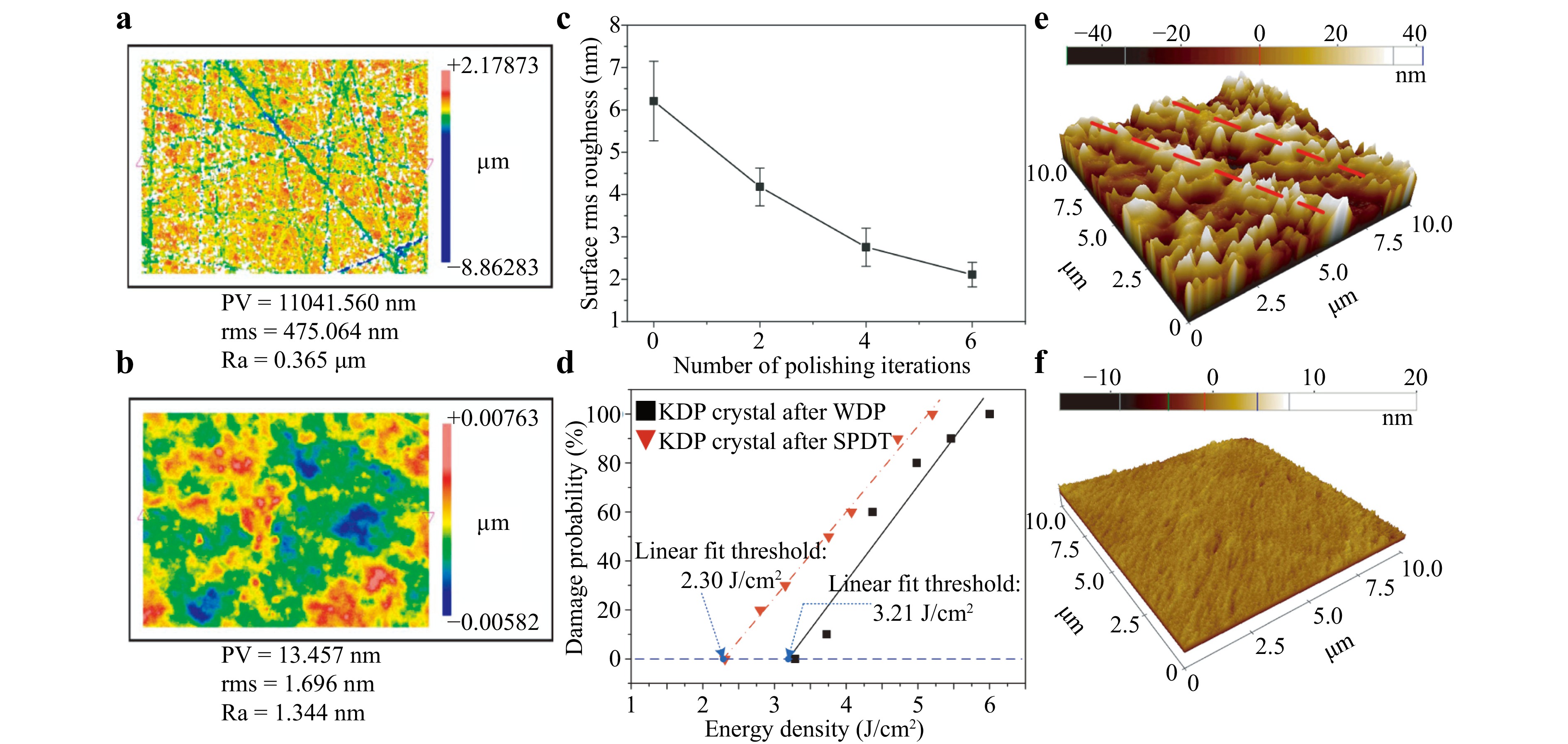
Fig. 6 a, b Surface morphologies of KHxD2-xPO4 crystal optic a before and b after WDP. These surface morphologies are obtained by Newview 5022, Zygo. The sizes of measurement area are 350 × 260 μm2. Reproduced with permission51. Copyright 2010, IOP Publishing. c Evolution of surface roughness with respect to number of polishing iterations. d LIDT after WDP and single-point diamond turning. e, f Atomic Force Microscope (AFM) images after e single-point diamond turning and f WDP, and their corresponding surface rms roughness is e 12.160 nm and f 0.842 nm, respectively. Adapted with permission69. Copyright 2015, Springer Nature.
In conclusion, manufacturing KHxD2-xPO4 optics via WDP with a microemulsion as the slurry base could yield high surface quality and inhibit the formation of SSDs, thus improving the laser damage resistance of the resulting optics; however, the efficiency of the process and surface quality of the resulting optics are contradictory. Nonetheless, the abrasive particle embedding problem does not occur, and the surface compositions of the KHxD2-xPO4 optics remain unchanged after WDP. Combining the CCOS and WDP could realise the rapid manufacture of large-aperture KHxD2-xPO4 optics. In addition, the microemulsion could be used as an etchant to etch the whole optic via ultrasonic-assisted control. However, the residual microemulsions need to be cleaned up through additional post-procedures. The contact between the polishing pad and the crystal surface might also cause mechanical defects. Lastly, protective blocks should be used to inhibit the edge effect to improve surface accuracy.
-
In WDP, the mechanical contact between the polishing pad and the optic could damage the soft-brittle surface of the KHxD2-xPO4 optic. By contrast, abrasive jet polishing is an ultra-precision manufacturing technique with advantages in terms of high precision, easy control, weak mechanical force, and no thermal deformation76–78. However, the abrasive particles might get embedded in the KHxD2-xPO4 optic because of its soft-brittle surface79. To avoid the potential damage caused by abrasive particles, abrasive-free jet polishing (AFJP) is proposed. This method employs an ionic liquid microemulsion (ILM), which contains a small amount of water instead of a traditional slurry. The KHxD2-xPO4 substrate materials are removed through nanoscale dissolution based on their deliquescence property. AFJP could be used to inhibit the formation of SSDs in KHxD2-xPO4 optics without embedding abrasive particles and introducing new residual stresses and subsurface defects80. The ILM, which is composed of bmimPF6, Triton X-100, and deionised water, exhibits thermodynamic and kinetic stability and could easily be cleaned up80–82. The Triton X-100 reduces interfacial tension, which is critical for the formation of nanoscale water droplets, whereas the water droplets are evenly dispersed in the non-aqueous carrier fluid. The water content is very important; a high water content would destroy the compatibility between ILM and KHxD2-xPO4 optic, resulting in corrosion pits82. The development of a stable, low-viscosity ILM is crucial to manufacturing KHxD2-xPO4 optics with high-quality surface, ultimately enhancing their laser damage resistance83,84.
As shown in Fig. 7a, under a free state, the water molecules in the ILM are wrapped by a long-chain surfactant, forming nanoscale water droplets that are isolated from the crystal surface. When the ILM collides with the surface, the long-chain surfactant barriers are broken, and the water droplets dissolve and remove the material. When water droplets that contain the KHxD2-xPO4 leave the surface, the surfactants form new molecular layers that wrap them again. The contact time between the water droplets and the surface is very short, and each water droplet dissolves a small amount of the KHxD2-xPO4 and then instantly moves away from the surface. Therefore, recrystallisation could be avoided. AFJP has two material removal modes: contact removal and slipping removal, as shown in Fig. 7b81. According to the normal impact velocity field, the processing area could be divided into the free jet region, impingement region, and wall jet region. In the impingement region, contact removal dominates, whereas in the wall jet region, slipping removal dominates. AFJP could remove the lattice misaligned structure and surface deformation layer, and reduce the area rms roughness (Sq) from 17.77 nm to 11.08 nm, as shown in Fig. 7d. In addition, AFJP does not change the surface composition nor leave surface residue, and no additional Raman characteristic peaks would be introduced, as shown in Fig. 7c80–82.
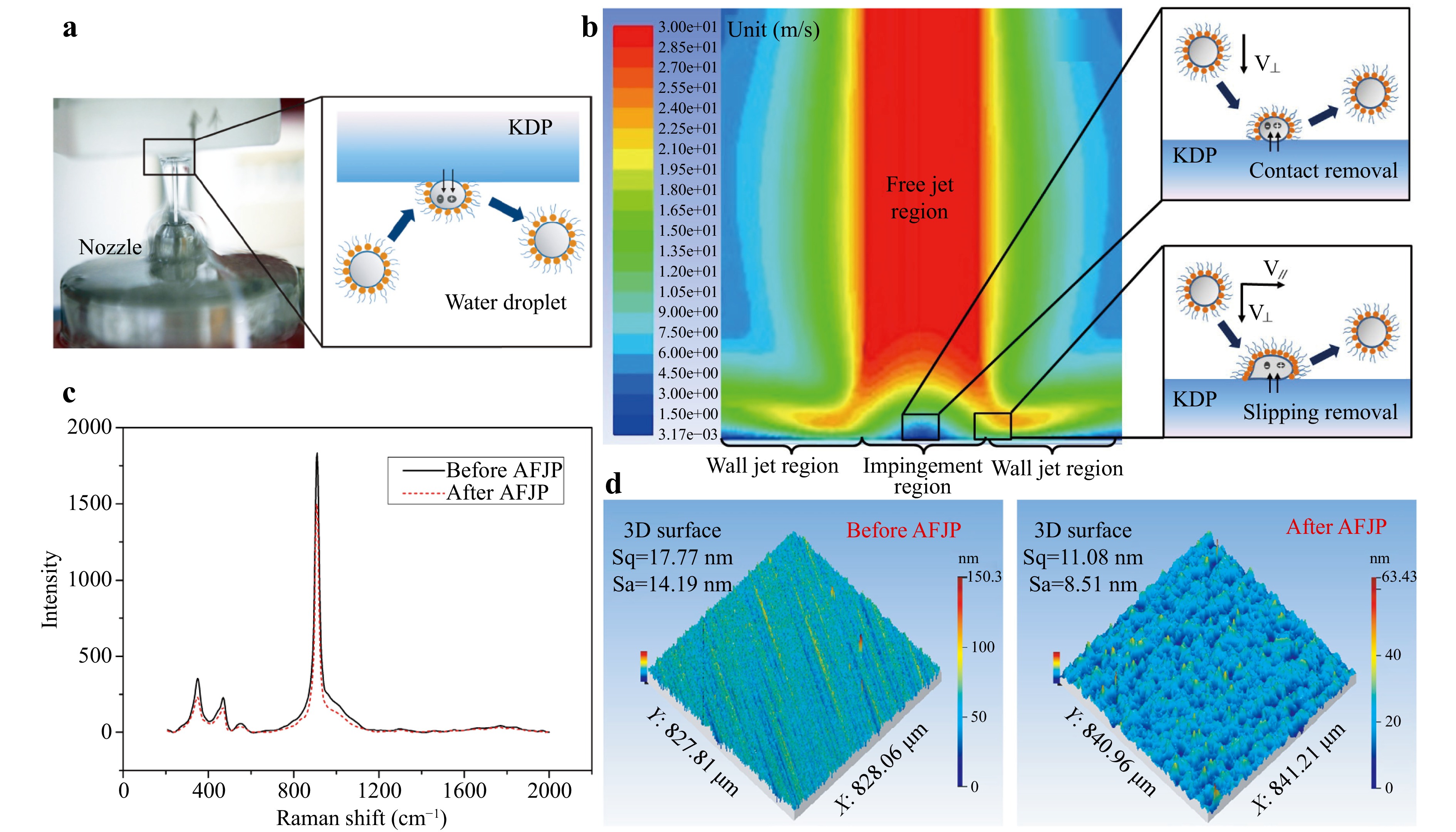
Fig. 7 a Processing principle and b removal mechanism of AFJP. c Raman spectrum and d surface roughness of KHxD2-xPO4 optics before and after manufacturing by AFJP. a Reproduced with permission80. Copyright 2018, Optical Society of America. b–d Reproduced with permission81. Copyright 2018, Optical Society of America.
In conclusion, AFJP could be used to inhibit the formation of SSDs in KHxD2-xPO4 optics through nanoscale dissolution. There is neither thermal effect nor mechanical contact from a polishing pad or abrasive particles; thus, AFJP would not introduce new mechanical defects. Moreover, the ILM could be cleaned up easily, and the surface compositions would not be changed. However, the LIDTs of KHxD2-xPO4 optics resulting from AFJP are unclear. It is insufficient to evaluate the improvement effects of AFJP only from the perspective of surface quality. It is necessary to conduct laser damage resistance tests or adopt other detection techniques to explore the changes in laser damage precursors that occur during AFJP. Lastly, the high viscosity of the ILM and the bubbles in the microemulsion recycling system create challenges for AFJP.
-
MRF is a flexible polishing technique that uses the rheological properties of magnetorheological (MR) fluid to process the optical surface with small positive pressure, as shown in Fig. 8a. First, the MR fluid is sprayed on a polishing wheel. Then, the polishing wheel carries the MR fluid through the gap between the polishing wheel and the optics, and a flexible polishing ribbon is formed under the action of a magnetic field. Finally, relative motion occurs between the polishing ribbon and the workpiece at the contact position, which removes the surface material. MRF is insensitive to machine tool vibration and accuracy, making it easy to be control, thus guaranteeing a high surface quality. However, conventional MRF faces great challenges when processing KHxD2-xPO4 optics because KHxD2-xPO4 is highly deliquescent and soft-brittle. The water in the conventional MR fluid would cause surface corrosion and fog, whereas the iron powders and abrasive particles can easily scratch and be embedded in the crystal surface85. The key to inhibiting formation of SSDs in KHxD2-xPO4 optics manufactured via MRF is to appropriately design the MR fluid, which should contain at least four components: non-aqueous carrier liquid, carbonyl iron particles (CIPs), stabiliser, and chemical buffer86. Owing to the CIPs, when a gradient magnetic field is applied to the MR fluid, its viscosity is significantly enhanced, and the rheological property changes, turning the MR fluid into a viscoplastic Bingham body. The non-aqueous carrier liquid is the heart of the MR fluid, and by increasing the amount of this liquid, the surface quality of KHxD2-xPO4 optics could be improved87,88. The LIDT of KHxD2-xPO4 optics could increase 2.0–4.9 and 1.6–2.1 times for infrared (1064 nm, 10 ns) and visible (532 nm, 7.5 ns) lasers when alkoxy alcohols are used for the non-aqueous carrier liquid86.
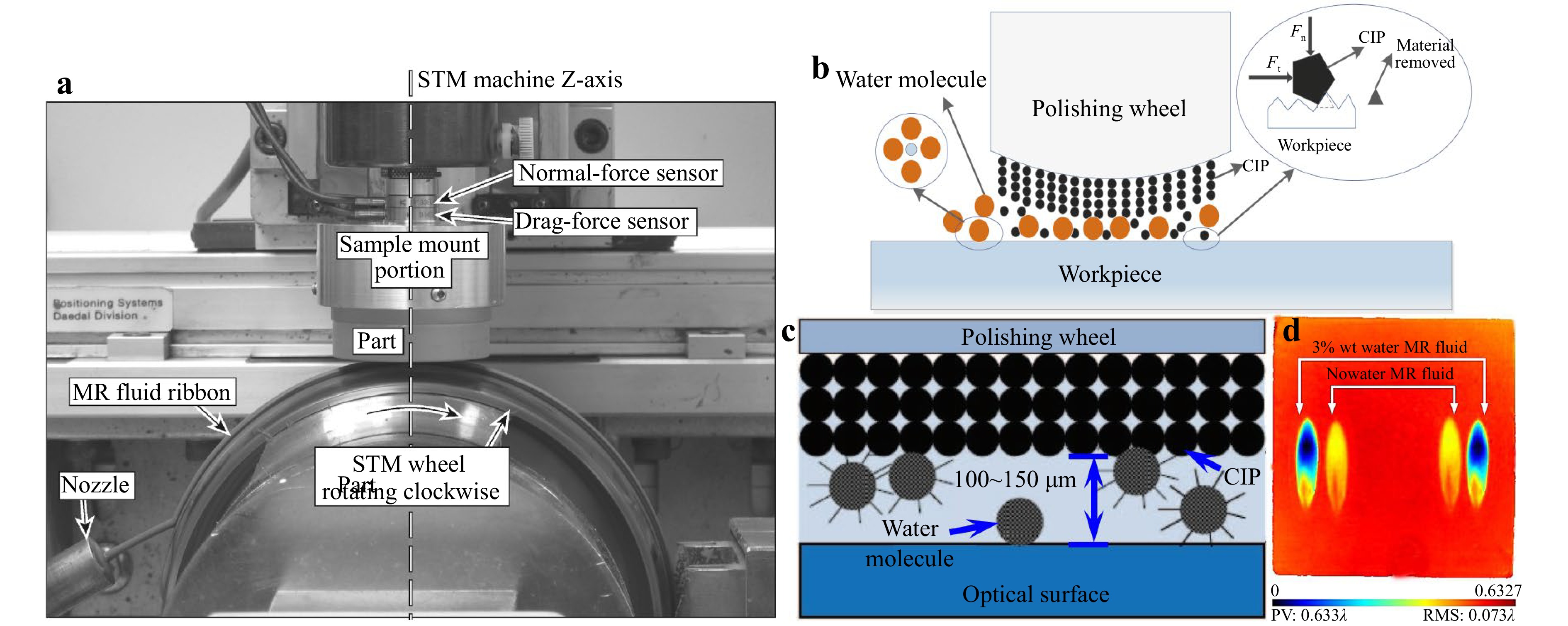
Fig. 8 a Manufacturing processes in MRF. Reproduced with permission91. Copyright 2009, Optical Society of America. b Schematic of material removal mechanism. Reproduced with permission89. Copyright 2018, Elsevier. c Mixed phase formed by water and non-aqueous carrier liquid. Adapted with permission90. Copyright 2011, Chinese Laser Press. d Comparison of removal spots with 0% and 3% wt water. Reproduced with permission89. Copyright 2018, Elsevier.
For non-aqueous MRF, the material removal depends mainly on mechanical action, resulting in low efficiency. Furthermore, the removed materials may be recrystallised, forming KHxD2-xPO4, K2HP, K3P, etc., on the surface of the optics86,92. Adding water to the MR fluid could not only inhibit the recrystallisation but also increase the material removal rate89,90,93. As shown in Fig. 8b, the surface materials are removed mainly through the water-solution effect, and very small amounts of material are mechanically removed by the CIPs. The water and the non-aqueous carrier liquid would form a mixed phase, as shown in Fig. 8c90. The water molecules are wrapped by the membrane and isolated from the surface; however, when the membrane is broken under external pressure, the surface materials are dissolved in the water. Therefore, adding a small amount of water would not cause surface corrosion or fog; however excessive amounts of water would lead to uncontrollable MRF removal and deteriorate the surface quality of the manufactured optics. For MR fluid with water, the water-dissolution removal plays a dominant role, as shown in Fig. 8d, and a small amount of water could dissolve large amounts of the KHxD2-xPO4 because of its high solubility in water, which ensures the stability of the MRF removal and is conducive to processing large-aperture KHxD2-xPO4 optics. However, for MRF with long dwell times, a supersaturated solution would be formed via the excessive dissolution of crystals into the MR fluid, resulting in the recrystallisation of K3PO4, K2HPO4, etc., on the surface94.
The surface micro-waviness in KHxD2-xPO4 optics introduced by single-point diamond turning is disadvantageous to laser damage resistance. MRF could reduce spatial middle- and low-frequency errors but has difficulty inhibiting spatial high-frequency errors89,90,95. For spiral-cutting surfaces, MRF could inhibit only the spatial low-frequency errors, whereas for fly-cutting surfaces, MRF could inhibit both the spatial middle- and low-frequency errors, as shown in Fig. 996. To remove the tool marks introduced by single-point diamond turning, the velocity direction of the polishing wheel should be perpendicular to the tool marks; however, a better surface roughness could be obtained when they are parallel. Furthermore, because of the anisotropy of the KHxD2-xPO4 crystal, better surface roughness could be obtained when both sides of the polishing direction possess the same structural features85.
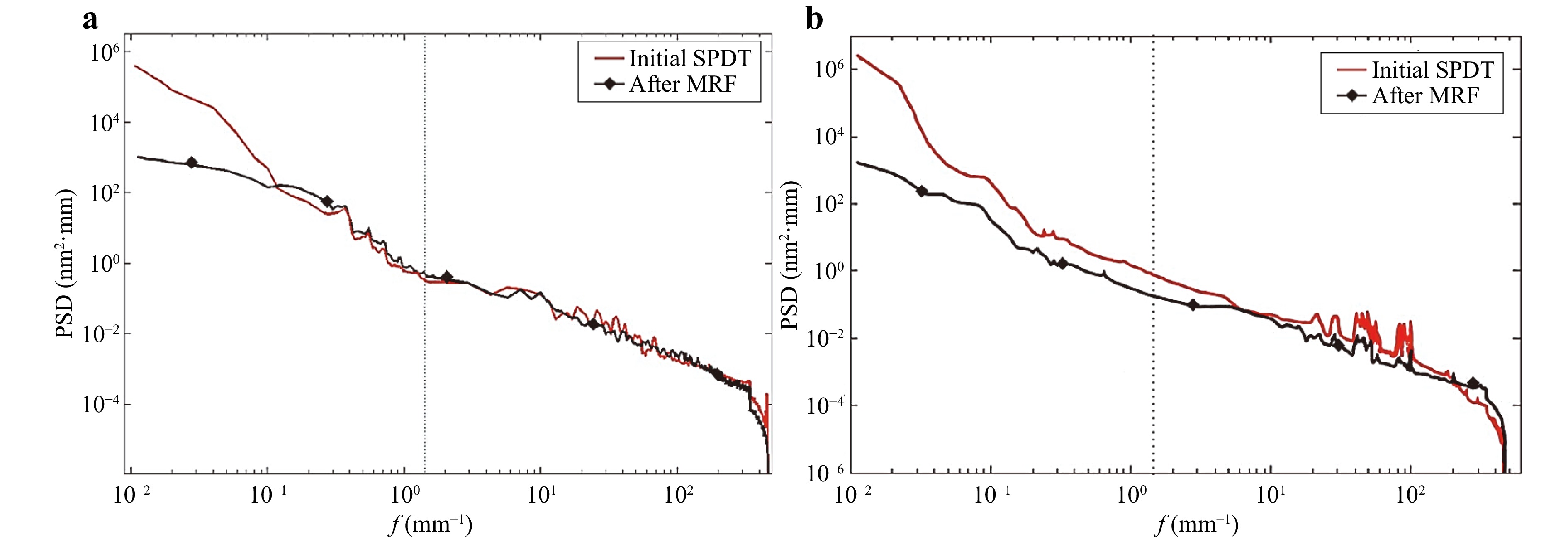
Fig. 9 PSD curve of a a spiral-cutting, b fly-cutting KHxD2-xPO4 crystal optic manufactured by MRF. Reproduced with permission96. Copyright 2016, Optical Society of America.
The low efficiency of MRF is a major challenge for manufacturing large-aperture KHxD2-xPO4 optics. Through the addition of nano-diamond powders, the efficiency of MRF could be improved, and the grooves caused by the MR fluid flow could be inhibited; however, the surface of the KHxD2-xPO4 optics may be damaged86,92. Another method is to adjust the temperature to change the solubility of the KHxD2-xPO4 in water to improve the efficiency of the manufacturing process. When the temperature of the MR fluid is increased from 294 K to 302 K, the volume removal rate increases by 49.1%97. However, when the temperature difference between the MR fluid and the crystal surface is exceedingly large, a halo region would appear in the MRF removal spots, thus decreasing the surface quality. If the KHxD2-xPO4 optics and the MR fluid were to be heated simultaneously, the humidity threshold for anti-deliquescence could be improved, and the efficiency of the MRF could be further increased98.
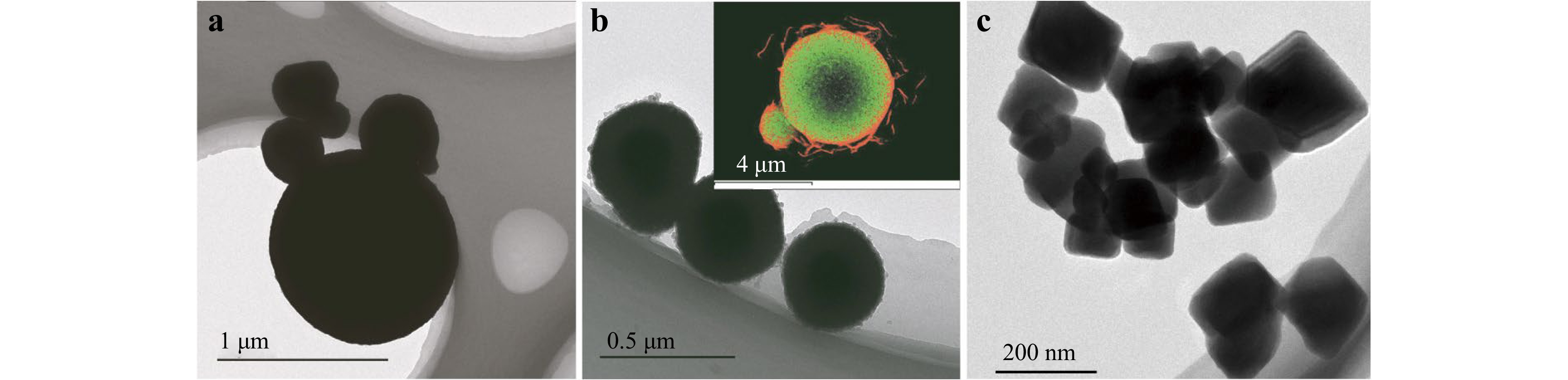
The soft-brittle surfaces of KHxD2-xPO4 optics can be easily damaged by CIPs and abrasive particles90,99,100. Although the CIPs would inevitably participate in the MRF processes, as shown in Fig. 8c, they would be tightly adsorbed on the polishing wheel. Furthermore, there is a region in the outermost layer of the polishing ribbon where the CIPs are barely present. Therefore, the mechanical actions of the CIPs could be avoided by optimising the MRF parameters accordingly. Additionally, surface modification could be performed to reduce the surface hardness of the CIPs using a methoxy-polyethylene-glycol (MPEG) coating to inhibit the mechanical defects caused by the CIPs, as shown in Fig. 10b95. The MPEG coating could reduce machining stress and enhance the compatibility of the CIPs with the KHxD2-xPO4 and the carrier liquid89,93,95. Another method is to use low-hardness cubic Fe3O4 nanoparticles instead of both CIPs and abrasive particles, as shown in Fig. 10c, which could yield a higher surface quality101. However, the small size (100–200 nm) and low saturation magnetisation of cubic Fe3O4 nanoparticles would lead to weak shear stress, resulting in low efficiency. Residual MR fluid could also pollute the KHxD2-xPO4 optics, which should be cleaned up via soaking cleaning with ultrasonics, IBE, etc.99,100,102. Combining MRF and IBE could improve the LIDT of the KHxD2-xPO4 optics from 4.98 J/cm2 to 9.2 J/cm2, 355 nm, 10 ns100. Additionally, a novel MR fluid, which utilizes amorphous SiO2 nanospheres as the abrasive particles, has recently been developed for manufacturing KHxD2-xPO4 optics103. And the amorphous SiO2 nanospheres, of which sizes are concentrated in the range of 40–60 nm, contribute to enhancing the surface uniformity of KHxD2-xPO4 optics.
In conclusion, MRF could be used to inhibit the formation of SSDs in the KHxD2-xPO4 optics and improve the surface spatial frequency errors and surface roughness. However, MRF may cause new defects such as surface contaminations, scratches, and embedded CIPs in the KHxD2-xPO4 optics, which should be inhibited by optimising the composition of the MR fluid or combining MRF with other post-processing techniques. In addition, MRF is inefficient and time-consuming, and the evaporation and hygroscopicity of the carrier liquid would lead to changes in the water content of the MR fluid after a long processing time, thus affecting the stability of the MRF removal, which brings great challenges to its use in the manufacture of large-aperture KHxD2-xPO4 optics. To be able to employ MRF in an effective manner, it is necessary to continue to develop more effective and stable MR fluids.
-
For KHxD2-xPO4 optics, water-dissolution techniques can be chemically corrosive or mechanically damaging to their surfaces. As a non-contact dry etching technique, IBE exhibits high resolution (atomic-scale), good anisotropy, and no material limitation, and is therefore ideal for inhibiting the formation of SSDs in KHxD2-xPO4 optics without causing corrosion, fogs, or mechanical defects. Moreover, its vacuum environment could prevent the introduction of additional impurities. The material removal mechanism of IBE is physical bombardment between the surface materials and a stable beam of accelerated particles, as shown in Fig. 11a104. Plasma is generated from inert gas inside a chamber, and then the ions are accelerated by an electric field to improve their kinetic energies. A high-energy gas ion beam would be focused on the surface, and atoms are sputtered out by the physical bombardment. Through IBE, the surface accuracy and laser damage resistance of the KHxD2-xPO4 optics could be improved105,106. However, KHxD2-xPO4 is sensitive to temperature changes, and an excessive temperature gradient would lead to the cracking of the optics. Therefore, the thermal effects caused by the ion bombardment energy deposition need to be carefully considered to reduce the thermal stresses to prevent the KHxD2-xPO4 optics from cracking, as shown in Fig. 11b107. The thermal stress concentration caused by the temperature gradient is the main reason behind the cracking. The maximum stress that KHxD2-xPO4 could withstand is 10 MPa; thus, the maximum temperature gradient should not exceed 6.601 °C/mm107,108.
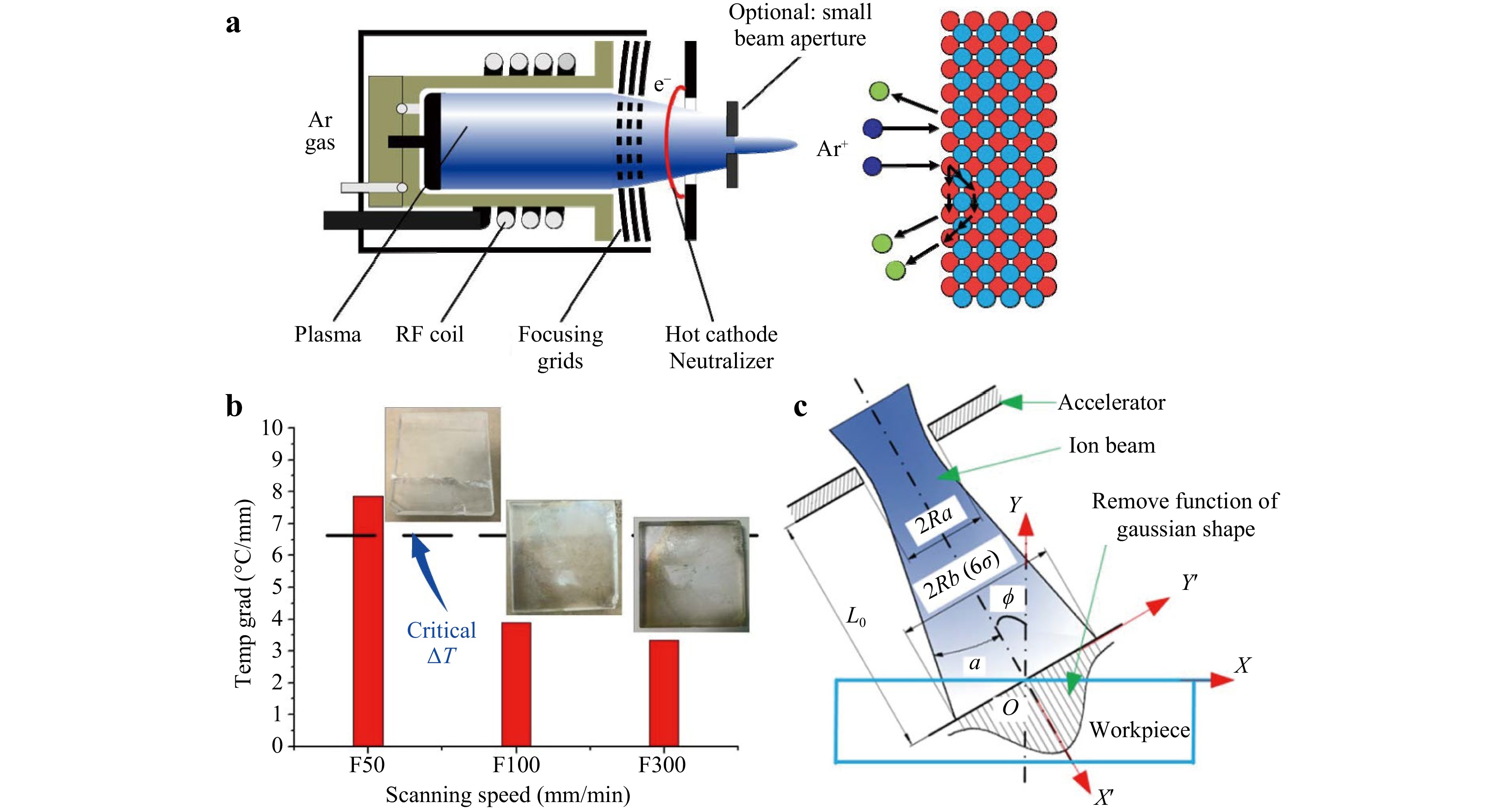
Fig. 11 a Material removal mechanism of IBE. Surface material is removed by argon ion bombardment. Reproduced with permission104. Copyright 2018, Society of Photo-Optical Instrumentation Engineers. b Cracking of KHxD2-xPO4 optic after IBE. Reproduced with permission107. Copyright 2016, Optical Society of America. c Schematic diagram of OI-IBE. Reproduced with permission108. Copyright 2017, Optical Society of America.
To prevent cracking, the IBE parameters should be strictly controlled to ensure a small temperature gradient inside the KHxD2-xPO4 optics. A faster scanning speed of the ion beam would induce a lower temperature field, whereas a lower scanning speed might result in the cracking of the optics, as shown in Fig. 11b. Another method is oblique-incidence IBE (OI-IBE), as shown in Fig. 11c108. OI-IBE exhibits less energy deposition, provides a higher material removal efficiency, and yields a better surface quality108,109. When the incidence angle is 60°, the peak and volume removal rates of OI-IBE are 1.84 and 2.59 times, respectively, higher than those of normal-incidence IBE. When the incidence angle is 45°, the surface peak-to-valley values (PV) decrease from 1.986 λ to 0.215 λ, whereas the surface rms roughness decreases from 2.385 nm to 1.474 nm. When the ion beam is obliquely incident, the sputtering removal rate of the micro-wave peak on the crystal surface becomes higher than that of the micro-wave trough, and the ion bombardment would cause the thermal flow of the surface atoms, resulting in a smooth surface102.
The surface temperature of the KHxD2-xPO4 optics could reach over 350 K during IBE105. This temperature is equivalent to that of thermal annealing, which could eliminate defects, reduce residual stress, and improve laser damage resistance. IBE could also be used to inhibit the formation of surface defects such as small-scale ripples, micro-pits, scratches, and cracks in the KHxD2-xPO4 optics, as shown in Fig. 12105,106. Additionally, the LIDT (355 nm, 10 ns) increases by 47.3%105. However, IBE would enhance the surface hydrophilicity, making the optics more likely to deliquesce, and thus, the storage environment should be strictly controlled. The LIDT decreases by 27.5% after deliquescence106. Nevertheless, as described earlier, IBE could be used to remove the residual impurities caused by MRF.
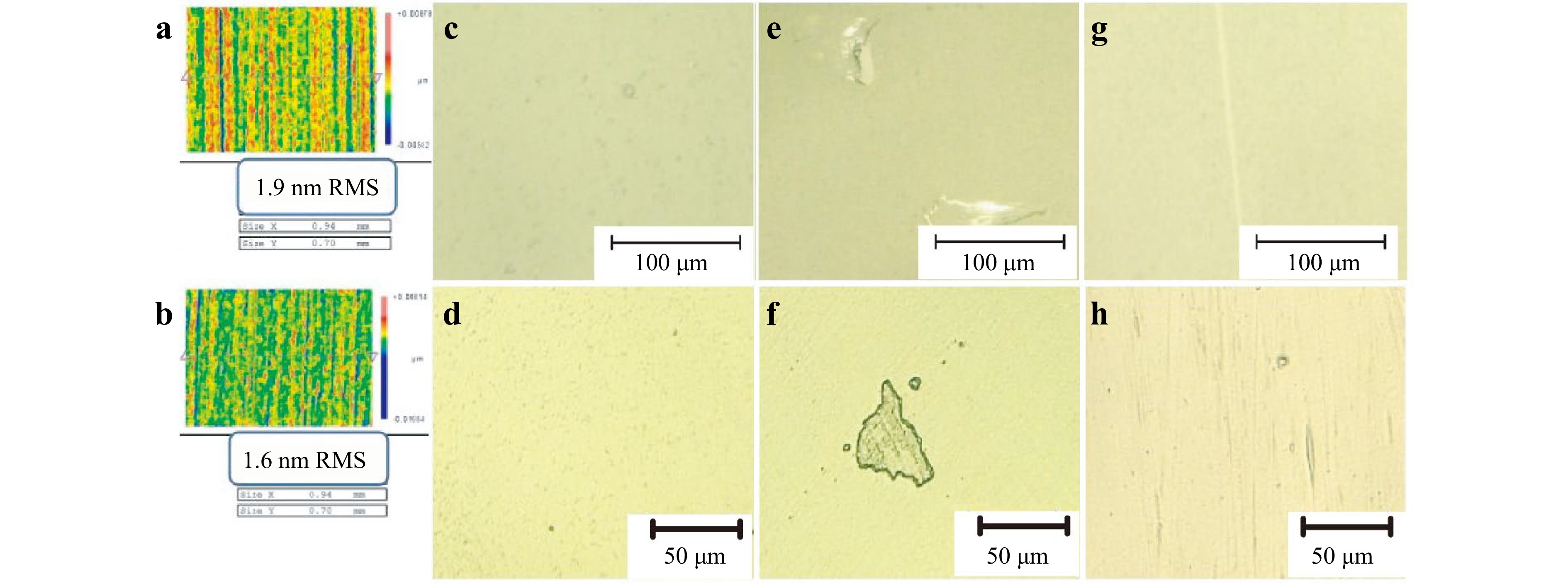
Fig. 12 a, b Surface rms roughness, c, d spot-shaped defects, e, f brittle structural defects, g, h scratches before and after IBE. Adapted with permission105. Copyright 2017, Society of Photo-Optical Instrumentation Engineers.
In conclusion, IBE could be used to inhibit the formation of SSDs to improve the laser damage resistance and surface quality of KHxD2-xPO4 optics. The thermal effect caused by IBE could anneal the KHxD2-xPO4 optics, however, a large temperature gradient would lead to the cracking of the optics. Moreover, the surface hydrophilicity of the KHxD2-xPO4 optics would be enhanced by IBE, thus bringing challenges for the storage and service environment. IBE is performed in vacuum to avoid foreign impurities and fogging; however, the vacuum equipment increases operation costs. In addition, the low efficiency of IBE limits its application for the manufacture of meter-sized large-aperture KHxD2-xPO4 optics.
-
Although all laser damage precursors could be removed at once by refinishing the KHxD2-xPO4 optics via the techniques described earlier, it is prudent to locally regulate these precursors, especially large-scale laser-induced surface damages and SSDs, via point-to-point manufacturing techniques to maintain the complete functionalities (e.g. frequency conversion) of the optics because only the local areas around the laser damage precursors are processed. Refinishing the entire optical surface is also time-consuming and costly and could introduce new SSDs. In addition, it is difficult to control the refinishing processes and formulate the strategies for processing the optics because laser-induced surface damages are complex and have different characteristics. At present, point-to-point manufacturing techniques for locally removing laser damage precursors in KHxD2-xPO4 optics mainly encompass micro-milling, ball dimpling, and dip-pen nanolithography (DPN).
-
Laser-induced surface damage in optics can be catastrophic owing to the tendency of such damage to grow. Micro-milling is the most preferred manufacturing technique for locally repairing KHxD2-xPO4 optics110,111. Micro-milling provides a controllable contour with high surface quality and good stability in eliminating laser-induced surface damage, resulting in repaired sites with laser damage resistance that could even exceed that of the undamaged surface. The Lawrence Livermore National Laboratory (LLNL) first attempted to repair laser-induced surface damage via ultra-precision turning112. The repaired sites remained unchanged after 600 shots of 12 J/cm2, 351 nm, 11 ns laser irradiation. The friction between the tool and the crystal surface would produce high local temperatures, which is conducive to forming a smooth repaired contour and improving the repair effect. Afterward, ball-end milling is used to reduce the size of the repaired site for laser-induced surface damages of the same size and produce repaired contours that are benign to the laser system113. No matter whether the crystal optics have anti-reflective (AR) coating or not, no damage would occur at the repaired sites after 200-300 shots of 12 J/cm2, 351 nm, 8 ns laser irradiation. The developments in micro-milling as a technology are summarised in Fig. 13112–115. The repair contours have developed from a dimple shape, to the rotation shape of an R–θ–Z configuration, and then to an arbitrary shape of X–Y–Z configuration.
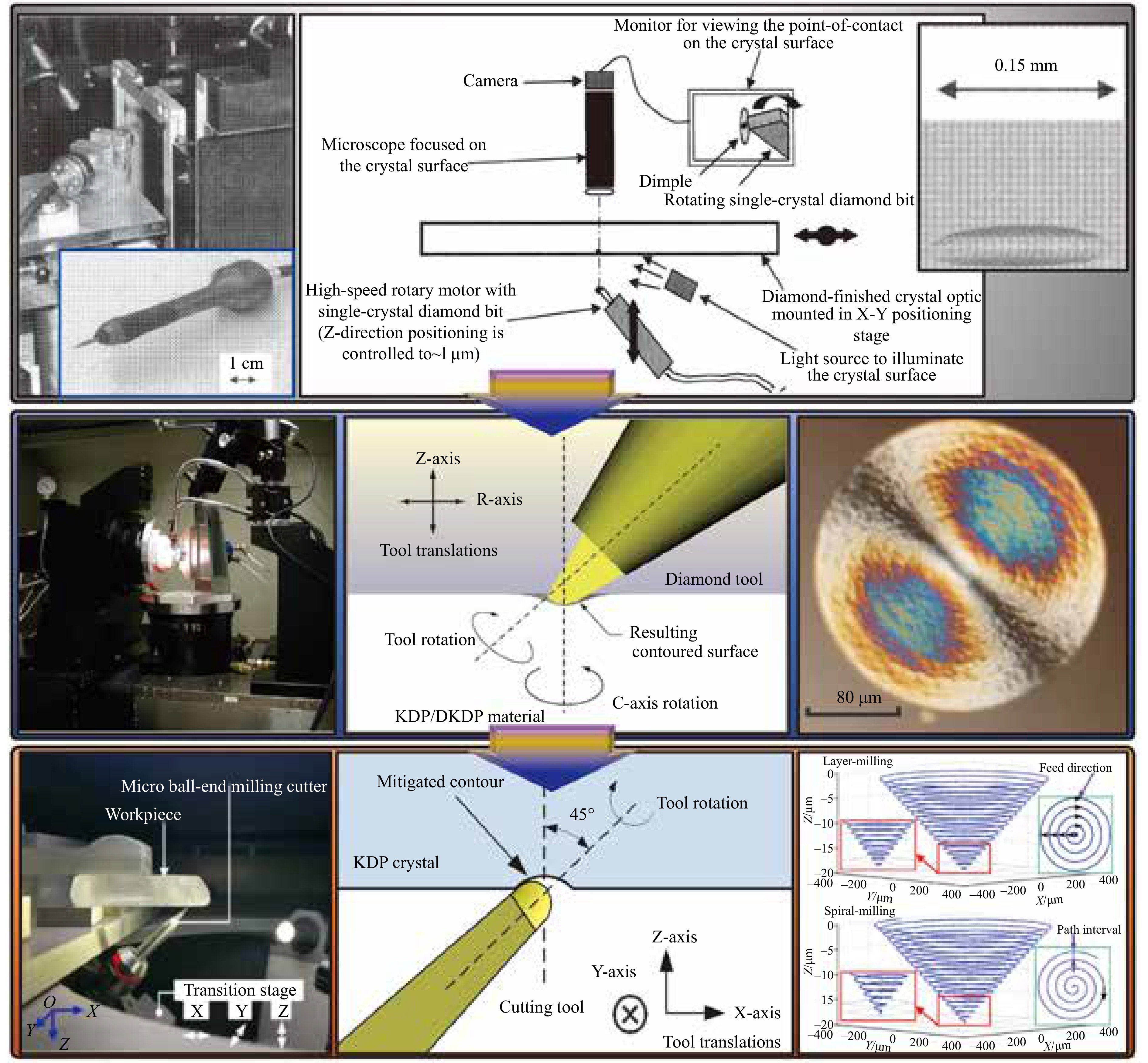
Fig. 13 Developments in micro-milling. Top: Micro-machining device initially adopted by the LLNL. The repair contour is a strip dimple. Adapted with permission112. Copyright 2004, Society of Photo-Optical Instrumentation Engineers. Middle: Typical micro-milling device with R–θ–Z configuration. The repair contour shown on the right is Gaussian. Adapted with permission113. Copyright 2007, Society of Photo-Optical Instrumentation Engineers. Bottom: Typical micro-milling device with X–Y–Z configuration. The repair contour shown on the right is conical. Adapted with permission114. Copyright 2019, Optical Society of America. Adapted with permission115. Copyright 2017, Society of Photo-Optical Instrumentation Engineers.
To avoid material crushing and fractures caused by the zero cutting velocity point, the tool spindle and the crystal surface should be arranged at a tilt angle, as shown in Fig. 13. Ensuring the ductile cutting of the soft-brittle KHxD2-xPO4 optics is very important for obtaining a high surface quality. Otherwise, brittle cutting would lead to numerous micro-cracks, micro-pits, etc., which should be avoided by optimising the tool structure and cutting parameters116–120. The minimum undeformed chip thickness (UCT) and size effect are closely related to the brittle–ductile transition. When the ratio of feed per tooth to cutting edge radius is 0.7, a repaired surface with almost no ploughing effect and brittle cutting could be achieved120. The cutting-mode transition that occurs as the UCT is increased can be derived by calculating the specific energy dissipation based on fracture mechanics49. Another challenge in micro-milling is the residual debris, which could become new damage precursors that could seriously reduce the laser damage resistance of the optics36. These debris could be removed by using a high-velocity air flow112,121.
The laser modulation caused by the repaired contour is a major challenge for micro-milling. The commonly used contours are spherical, Gaussian, and conical115,122. Their transmittances at 355 nm are 90.58%, 90.32%, and 90.59%, respectively, which would not cause large fluence loss. However, the repaired contour would modulate the incident laser, reducing the laser damage resistance of the KHxD2-xPO4 optics and threatening the safety of downstream optics123,124. The light intensification caused by the spherical and conical contours is weaker than that caused by the Gaussian contour, and their laser damage resistance is higher115,125. Therefore, the spherical and conical contours are recommended. For the repaired contour on the rear surface, the total internal reflections should be responsible for the largest light intensification inside the optics126. Increasing the width–depth ratio of the repaired contour is beneficial for reducing the light intensification, and for spherical and Gaussian contours, it is recommended that this ratio should be greater than 5.3 and 4.3, respectively125. However, excessively large contours would cause greater material and fluence losses, whereas the light intensification is almost unchanged when the width–depth ratio is increased to a certain value. Therefore, the width and depth of repaired contour should be optimised according to the laser-induced surface damage size and the desired transmission performance, especially the width–depth ratio effect.
As a contact manufacturing technique, micro-milling would inevitably cause tool marks. These tool marks have two possible sources: tool wear and tool path, as shown in Fig. 14114,126–128. The light intensity enhancement factors (LIEFs) caused by a repaired contour with tool marks generated by tool wear on the front and rear surfaces are 2.1 and 5.9 times that without any tool marks. And the LIDT of a repaired contour with tool marks is only 83.6% of an ideal repair contour without any tool marks127. It is therefore necessary to check for tool wear regularly to ensure the repair quality. On the other hand, tool marks generated by the tool path are periodic structures, and the resultant LIEF could reach 5.6 times that of the ideal repair contour122. These tool marks have two key characteristics: period and residual height. A period determines the modulation degree and light intensity distribution in the optics. A period away from the incident laser wavelength could reduce the laser modulation. However, an excessively long period would increase the surface roughness, whereas an excessively short period would decrease efficiency. The period also affects fluence loss; the transmittances at 1064 nm given a period of 1 μm and 20 μm are 87.3% and 87.9%122. The residual height could affect the laser modulation slightly, and as the residual height increases, the modulation degree also increases. A combination of layer milling and spiral milling could improve the repair efficiency and control the creation of periodic tool marks to ensure the quality of the optics surface114,115. The Gaussian pseudo-random trajectory generation method could reduce the laser modulation and spatial high-frequency errors by disrupting the periodicity of the tool marks. The machine tool vibration might also generate periodic tool marks along the tool path, which should be studied further.
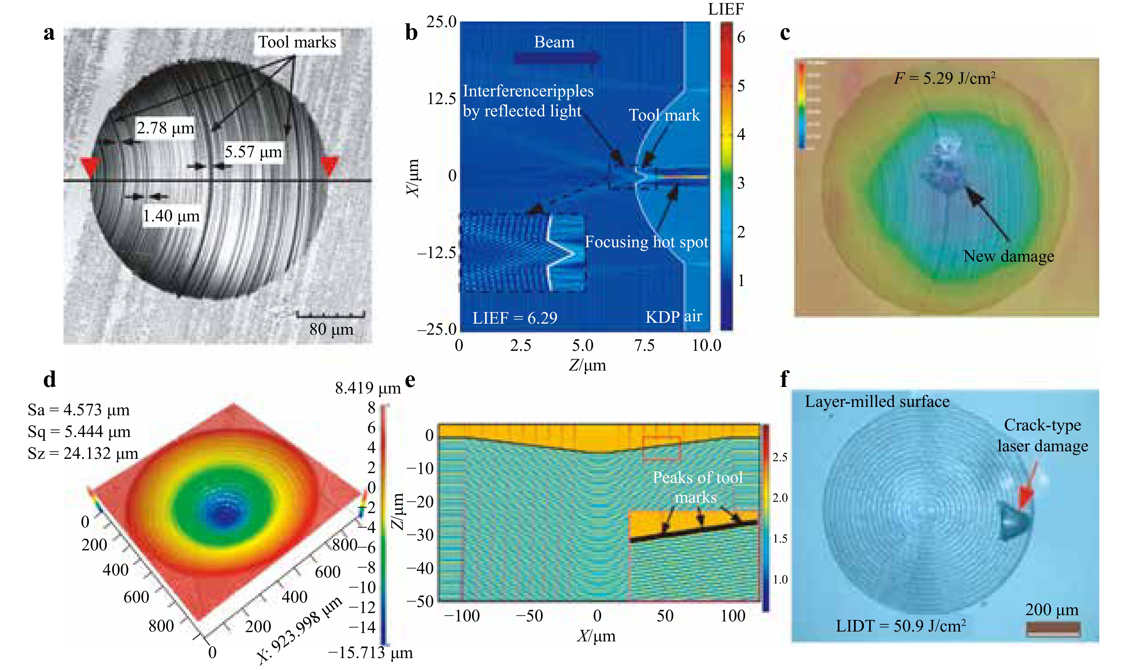
Fig. 14 a Tool marks generated by tool wear. b Laser modulation caused by spherical repair site with single tool mark generated by tool wear. c Laser damage resistance test result for repaired surface with tool marks generated by tool wear. Adapted with permission127. Copyright 2015, Springer Nature. d–f same as (a–c) but with tool marks generated by the tool path. Reproduced with permission114. Copyright 2019, Optical Society of America.
AR coatings on KHxD2-xPO4 optics bring new challenges for micro-milling. Repaired sites in AR-coated crystal optics without laser-induced surface damages could have high laser damage resistance113. However, it is difficult to remove solvent-persistent coating and burned-in coating without damaging the surface. Elhadj et al. developed a set of process flows to locally repair laser-induced surface damages with laser-damaged AR coating121. Apart from micro-milling, this process flow adopts solvent soaking and ultrasonication to remove the AR coating. The LIDT of the repaired site could reach 12 J/cm2, 351 nm, 5 ns. This method provides a potential scalable recycling loop for KHxD2-xPO4 optics. A more effective method for removing laser-induced surface damages with laser-damaged AR coating should be explored in the future. Besides, pre-existing micro-defects on KHxD2-xPO4 optical surface have a remarkable impact on the micro-milling repair process by affecting thermal load and UCT129. It is discovered that fracture pits and plastic scratches can reduce UCT and increase energy consumption, leading to a brittle to ductile transition and improving surface quality130. However, surface protuberances have opposite effect on the ductile removal ability and specific cutting energy during repair process. Although cracks and convex scratches increase uncut chip thickness, these two types of surface defects have no significant effect on the micro-milling repair process131.
In conclusion, micro-milling could effectively repair laser-induced surface damages in KHxD2-xPO4 optics to mitigate damage growth. Micro-milling is a promising local regulating technique that could provide a high-quality surface, controllable repair contour, and stable repair effect. Furthermore, its efficiency and operation accuracy could be improved with the aid of machine vision. However, micro-machining has the following disadvantages. The highly adherent machining debris could cause secondary damage, and the repaired contour would modulate the incident laser. Multiple repaired sites and tool marks would aggravate the laser modulation. The repaired sites usually have large sizes to remove the laser-induced surface damages completely and reduce the laser modulation, resulting in greater fluence losses. Laser-damage-affected coatings are also difficult to be removed solely by micro-milling. Ductile cutting should be ensured to obtain a high-quality surface, which would reduce the efficiency (to approximately 1 h/site). Currently, the applicability of the repair process is limited to laser-induced surface damages with sizes less than 350 μm. In the NIF, once laser-induced surface damages reach a critical size (approximately 0.5 mm and 1 mm for the front and rear surfaces, respectively), it is more economical to use a blocker. The optics would then be refinished when up to approximately 3–7 blockers have been accumulated. However, KHxD2-xPO4 optics could be refinished only 2–3 times, and new SSDs might be introduced. Therefore, it is necessary to optimize the micro-milling to improve its repair quality and economy.
-
In addition to micro-milling, a local polishing technique called the ball dimpling method could be adopted to repair laser-induced surface damages in KHxD2-xPO4 optics, as shown in Fig. 1542. The material is removed by abrading the optics with a high-speed rotating ball end, resulting in repaired dimples that are smooth and controllable. However, this method has a low efficiency, and the surface quality of the repaired site is not as good as that produced by micro-milling. Different abrasive media could be used for the ball dimpling method. Using Drakeol for the abrasive media and diamond grains with a size of 1 μm create a poor surface quality. The surface quality could be improved by adding Struers DP Suspension A, an alcohol-based fluid, into the abrasive media, but the deposition is difficult to clean up. Using Presi Mecaprex instead of an alcohol-based fluid is more efficient for surface cleanliness. Furthermore, the use of glass and basalt balls are preferred for this method. The dimples produced by different rotation axis tilts are shown in Fig. 15b. When the rotation axis tilt is 0°, the dimple edge is well defined without any chipping, the concentric polishing marks are significant, and residual contaminants can be observed at the dimple bottom. When the rotation axis tilt is 20°, the left side of the dimple corresponding to the acute angle between the surface and rotation axis shows irregularities and fractures at the bottom, whereas the right side corresponding to the obtuse angle is clean and regular, and no contaminant is observed at the bottom. Moreover, surface pollution is observed outside both dimples. Nonetheless, the ball dimpling method could also effectively mitigate laser-induced surface damage growth. After 20 J/cm2, 351 nm, 16 ns laser irradiation, laser-induced damage would occur only within the dimple. After 6000 shots of 18 J/cm2, 351 nm, 16 ns laser irradiation, laser-induced damage would no longer grow outside the dimple, indicating that the repaired site has good stability, as shown in Fig. 15c.
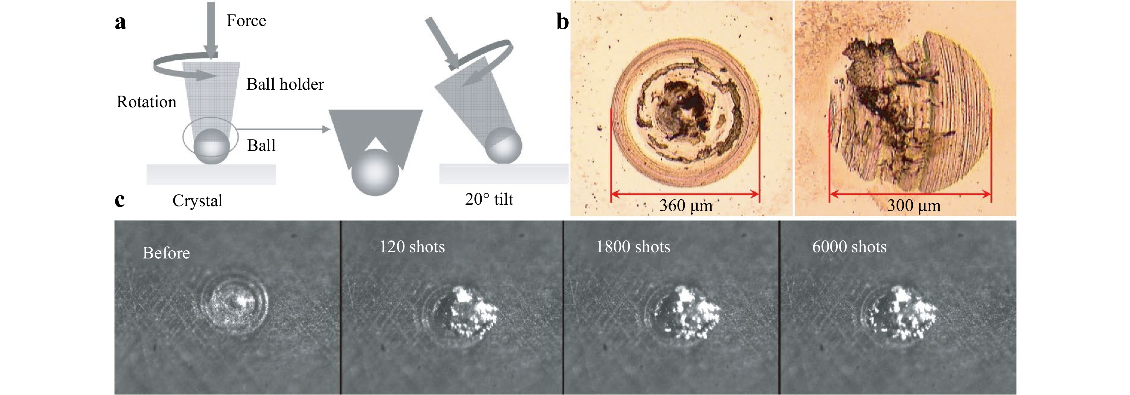
Fig. 15 a Ball dimpling method with different configurations (upright (left) and tilt (right)). b Dimples obtained by different configurations (upright (left) and tilt (right)). c Stability of the repaired dimple irradiated by 18 J/cm2, 351 nm, 16 ns laser. Reproduced with permission42. Copyright2007, Society of Photo-Optical Instrumentation Engineers.
In conclusion, although laser-induced surface damage growth in KHxD2-xPO4 optics could be effectively mitigated by the ball dimpling method, its repair results are not comparable to those of micro-milling. The laser modulation, fluence loss, tool marks, AR coating, brittle cutting, etc., problems that occur with micro-milling also occur for the ball dimpling method, bringing similarly great challenges to the process. In addition, the residual contaminants could also act as new laser damage precursors. To improve the ball dimpling method, its abrasive media may be replaced with the microemulsions used in the slurries for WDP and AFJP.
-
The number and size of surface defects in KHxD2-xPO4 optics have been greatly reduced with the improvement of optical manufacturing techniques. However, there remain numerous nanoscale laser damage precursors to be resolved. Recently, it has been suggested that a 3.0 MJ ultraviolet laser energy could pave the way for a new era of laser-driven inertial confinement fusion ignition. However, it is important to note that nanoscale laser damage precursors could cause significant laser-induced surface damages when exposed to such high-energy lasers. DPN is a promising local manufacturing technique for repairing the nanoscale laser damage precursors in KHxD2-xPO4 optics. DPN could imprint the nano-scale molecular patterns directly on the substrate and enable in situ imaging132,133. As shown in Fig. 16, DPN employs four key components: an atomic force microscopy (AFM) probe, ink, a meniscus, and a substrate134. Essentially, DPN is a material transport process that includes dissolution, diffusion, and self-assembly. First, ink molecules coating the AFM probe dissolve in the meniscus. Then, the ink molecules pass through the meniscus to the substrate. Finally, the ink molecules self-assemble to form a molecular layer on the substrate. The water meniscus is the material transport channel, which determines the material transfer rate and resolution. The key factors influencing the water meniscus are the relative humidity (RH), temperature, and surface hydrophilicity. KHxD2-xPO4 crystals are easily deliquescent and are categorised as a water-soluble material, which could be dissolved in the meniscus for transmission. Therefore, theoretically, DPN could be employed to process KHxD2-xPO4 optics in a local manner.
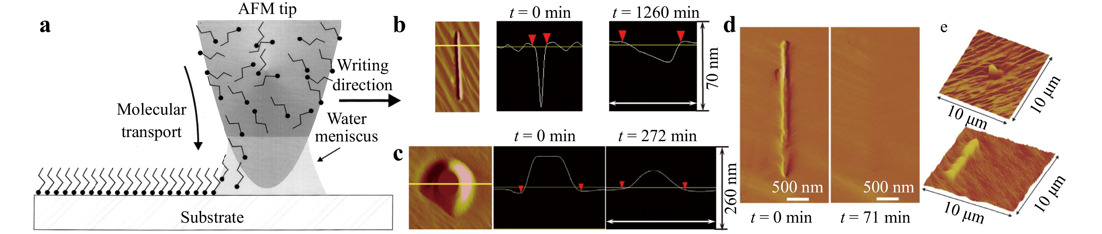
Fig. 16 a Schematic diagram of typical DPN process, which includes dissolution, diffusion, and self-assembly. Reproduced with permission134. Copyright1999, American Association for the Advancement of Science. b, c Evolution of the profiles of a (b) scratch and (c) mound on the KHxD2-xPO4 optic surface during DPN (RH = 85%). The scanning direction of the AFM probe and the scratch direction are perpendicular. Adapted with permission135. Copyright 2008, IOP Publishing. d Evolution of the profiles of a scratch when the scanning direction and scratch direction are parallel (RH = 85%). e Nano-dot and nano-wire fabricated by DPN. Reproduced with permission136. Copyright 2008, Wiley.
DPN was initially tested by the LLNL for the removal of nanoscale surface defects and fabrication of nano-structures in KHxD2-xPO4 optics135. In contrast to conventional DPN, the AFM probe does not carry any inks. The KHxD2-xPO4 would be dissolved in the water meniscus, and the dissolved materials would be redistributed as the AFM probe moves. The profile changes of the scratch and mound are shown in Fig. 16b, c135. The redistribution of the crystal materials is driven by the Gibbs–Thomson law, and the surface free energy decreases. Finally, the surface defects are inhibited, and the crystal surfaces are flattened. A surface scratch could also be removed by setting the scanning direction of the AFM probe to be the same as the scratch direction, as shown in Fig. 16d136. When the RH is35%, the thickness of the water film adsorbed on the crystal surface corresponds to a monolayer-to-submonolayer. Otherwise, when the RH is lower than 35%, surface reconstruction does not occur because the meniscus fails to form. Recently, a mathematical model has been developed by our research group to accurately predict the water meniscus condensed between the AFM probe and KHxD2-xPO4 optics137. Furthermore, dynamic behaviours of the water meniscus in response to the movement of the AFM probe has been further investigated in combination with computational fluid dynamics, demonstrating the stable existence of the water meniscus during DPN138. DPN could also be used to fabricate nano-dots and nano-wires on the crystal surface, as shown in Fig. 16e136. In our recent effort, AFM-probe-induced local heavy concentration of H2PO4− in a water meniscus was demonstrated to be a potential mechanism for nano-structure growth139. However, these nano-structures would gradually disappear when exposed to high humidity. The underlying mechanisms of this interesting phenomenon are still unclear, although they might be closely related to the increased surface free energy caused by the nano-structure.
In conclusion, DPN could be used to inhibit nanoscale surface defects in KHxD2-xPO4 optics. In contrast to the micro-milling and ball dimpling, there is no material loss during the DPN process, and thus, theoretically speaking, DPN could be manipulated infinitely. DPN could also be used to fabricate nano-structures on the surfaces of KHxD2-xPO4 optics. DPN has a unique application prospect because nanoscale laser damage precursors have attracted greatly increasing attention from researchers and operators with the increase in the laser performance requirements of high-energy/power laser facilities. Nonetheless, the following problems must be addressed to expand the application of DPN. First, its physical mechanism is unclear, and more theoretical studies are needed to investigate the changes undergone by the water meniscus and the material transport mechanism. Second, its processing efficiency is exceedingly low. It is therefore necessary to study methods to improve the efficiency, such as optimising the structure and improving the surface hydrophilicity of the AFM probe, and adding catalysts and external field assistance. Third, the crystal surfaces are covered with water films, which might cause surface modification. Therefore, the effects of the water films on the laser performance need to be explored. Fourth, it is insufficient to evaluate the improvement effect only from the perspective of surface planarisation. The chemical structure defects might also be inhibited. It is therefore necessary to test the laser damage resistance, transmittance, etc., of the crystal optics. Finally, the AFM probes carry no inks. The repair processes only redistribute the surface materials to remove the defects. If the AFM probes were to be coated with KHxD2-xPO4 as in traditional DPN, it could be a promising method to achieve the additive repair of nanoscale surface defects.
-
The service performance of nonlinear KHxD2-xPO4 crystal optics has been greatly improved by the development of advanced manufacturing techniques to regulate laser damage precursors (surface/subsurface defects and laser-induced surface damage), which has contributed greatly to the NIF achieving the first-ever fusion ignition in December 2022. As summarised in Table 3, each manufacturing technique offers its own advantages but is also beset by its own challenges, impeding the further improvement of the laser damage resistance of KHxD2-xPO4 optics.
Techniques Advantages Disadvantages and Challenges Main applications WDP ● Nanoscale dissolution.
● High efficiency.
● Abrasive-free.● Residual microemulsions.
● Surface fog/corrosion, edge effect.
● Defects caused by polishing pad.● Remove surface/subsurface defects.
● Mitigate laser-induced surface damage initiation.
● Precision polishing with water-soluble slurry (high efficiency, rms roughness: 5.0–40.0 nm).
● Ultra-precision polishing with water in oil microemulsion (rms roughness: 1.0–2.0 nm).
● Laser damage threshold: ~ 3.21 J/cm2,
355 nm, 6.8 ns, 1-on-1.AFJP ● Nanoscale dissolution.
● No mechanical contact.
● No thermal deformation.
● No recrystallisation.
● Abrasive-free.● Bubbles in ILM.
● High viscosity of ILM.
● Surface fog/corrosion.● Remove surface/subsurface defects.
● Mitigate laser-induced surface damage initiation.
● Rms roughness: ~ 10.0 nm.
● Laser damage threshold: 7.9–9.0 J/cm2,
351 nm, 1 ns, 1-on-1.MRF ● Nanoscale dissolution.
● Small positive pressure.
● Small residual stress.● Residual MR fluid.
● Grooves caused by MR fluid flow.
● Recrystallisation particles.
● Surface fog/corrosion.
● Defects caused by CIPs/abrasive particles.
● Stability of removal function.
● Low efficiency.● Remove surface/subsurface defects.
● Mitigate laser-induced surface damage initiation.
● Rms roughness: 0.6–2.0 nm.
● Laser damage threshold: ~ 6.8 J/cm2,
355 nm, 10 ns, 1-on-1.IBE ● Atomic-scale machining.
● No surface fog/corrosion.
● Annealing caused by thermal effect.
● Non-contact dry etching.
● High certainty & stability.
● No mechanical defects.
● No additional impurities.
● High surface quality.● High vacuum equipment costs.
● Low efficiency.
● Enhance surface activity.
● Surface nano-structuring behaviours.
● Sputtering damage.
● Cracks caused by thermal effect.● Remove surface/subsurface defects.
● Mitigate laser-induced surface damage initiation.
● Rms roughness: 1.2–2.0 nm.
● Laser damage threshold: ~ 7.4 J/cm2,
355 nm, 10 ns, 1-on-1.Micro-milling ● Controllable repair contours.
● Stable repair effect.
● Automate & batch repair.● Low efficiency, brittle cutting.
● Machining debris.
● Modulation, fluence loss, tool marks.
● Milli-scale repair contour.
● Laser-damage-affected coating.● Replace laser-induced surface damage site with controllable repair contours.
● Mitigate laser-induced surface damage growth.
● Size limitation: 20–350 μm.
● Rms roughness: 30.0–50.0 nm.
● Laser damage threshold: > 12.0 J/cm2,
351 nm, 8 ns, R-on-1.Ball dimpling ● Controllable repair contours.
● Stable repair effect.● Low efficiency, brittle cutting.
● Surface contaminant.
● Modulation, fluence loss, tool marks.
● Milli-scale repair contour.
● Laser-damage-affected coating.● Replace laser-induced surface damage site with controllable repair contours.
● Mitigate laser-induced surface damage growth.
● Size limitation: Not reported.
● Laser damage threshold: ~ 16.0 J/cm2,
351 nm, 16 ns, R-on-1.DPN ● Inhibiting nanoscale laser damage precursors.
● Nanoscale dissolution.
● High resolution, in situ imaging.
● No material loss.● Low efficiency.
● Deliquescence.
● Surface fog/corrosion.● Heal surface geometry defects.
● Regulate chemical structure defects.
● Mitigate laser-induced surface damage initiation.
● Size limitation: less than several micrometres.
● Laser damage threshold: Not reported.Table 3. Advantages and challenges of different optical manufacturing techniques
KHxD2-xPO4 is soft-brittle, easy to crack, deliquescent, sensitive to temperature change, and strongly anisotropic, bringing great challenges to regulating laser damage precursors in its optics. Water-dissolution polishing (WDP), abrasive-free jet polishing (AFJP), magnetorheological finishing (MRF), and dip-pen nanolithography (DPN) are all used to remove surface/subsurface defects (SSDs) using the deliquescence characteristic of the KHxD2-xPO4 material. The key to developing WDP, AFJP, and MRF is to continuously improve the performance of the polishing slurries. WDP is an abrasive-free manufacturing technique, and the only mechanical action induced is by the polishing pad under pressure. Different slurries have been developed for WDP, and of these slurries, microemulsions could achieve effective results in inhibiting SSDs to produce high laser damage resistance, although a post-cleaning procedure is needed to remove the residual contaminants. Compared with other water-soluble slurries, microemulsions are inefficient, but a good surface quality could be obtained because the dissolution is achieved by nanoscale water droplets. Combining WDP and computer-controlled optical surfacing (CCOS) could achieve the rapid processing of large-aperture KHxD2-xPO4 optics. AFJP is a promising surface processing technique developed in recent years and is another abrasive-free manufacturing technique based on nanoscale dissolution. AFJP does not involve any direct mechanical contact and does not introduce new residual stress and subsurface defects. Moreover, it does not yield abrasive particles that could be embedded in the surface. However, the high viscosity of the ionic liquid microemulsion (ILM) and the bubbles in the ILM recycling system bring challenges for AFJP. More research studies are needed to evaluate the effectiveness of AFJP in improving laser damage resistance in optics and to explore the changes it creates on laser damage precursors. MRF relies on the use of an MR fluid, of which magnetic particles are essential components, which would inevitably participate in the MRF process and damage the crystal surface. Therefore, the residual MR fluid on the surface needs to be cleaned up by an additional post-cleaning procedure. MRF is time-consuming, and the stability of the MR fluid would affect the stability of the removal function after a long processing time. Ion beam etching (IBE) is a non-contact dry etching technique, which is beneficial in view of the soft-brittle and deliquescent nature of the crystal and could achieve atomic-scale ultra-precision machining. The thermal effect caused by IBE could anneal the optics, whereas a large temperature gradient would lead to cracking. Additionally, the enhanced surface hydrophilicity makes the KHxD2-xPO4 optics more likely to deliquesce, bringing great challenges for the storage and service environment. Overall, WDP using water-soluble slurry is preferred for rapidly removing surface and subsurface laser damage precursors in the full-aperture KHxD2-xPO4 optics, thereby enhancing their laser damage resistance. Subsequently, iterative processing could be achieved through WDP with water-in-oil microemulsion slurry, MRF, IBE, or a combination of these techniques, which enables ultra-precision figuring of KHxD2-xPO4 optics, ensuring high laser damage resistance and surface profile quality. Furthermore, due to its advantages of non-contact processing, absence of mechanical damage, and pollution-free operation, IBE is often preferred as the final step in ultra-precision machining.
Dip-pen nanolithography (DPN) possesses the advantage of being able to locally remove nanoscale surface defects and leads to no material losses. Theoretically, this technique could be manipulated infinitely. DPN is also expected to achieve additive repair for nanoscale surface defects using a KHxD2-xPO4-coated AFM probe. Although the physical mechanism is unclear and the efficiency is low, DPN is worth focusing on in the future. On one hand, with the improvement of manufacturing techniques, the number and size of surface defects decrease significantly, providing the possibility for locally removing surface defects via DPN. On the other hand, with the increase in the laser performance requirements of high-energy/power laser facilities, removing nanoscale laser damage precursors becomes increasingly important. The effects of DPN on the laser performance of KHxD2-xPO4 optics need to be further explored.
Micro-milling is a promising manufacturing technique for locally repairing laser-induced surface damages in KHxD2-xPO4 optics to mitigate damage growth. This technique could provide a high-quality surface, controllable repair contour, and stable repair effect. However, it is difficult to remove laser-damage-affected coatings, if any, around laser-induced surface damage sites, for which it is more economical to use a blocker. Furthermore, the machining debris, tool marks, laser modulation, and fluence loss would affect the stability of laser beams used with optics. It is therefore necessary to optimise the micro-milling process to improve its repair quality and economy. Moreover, micro-milling could only be used to repair damage sites ranging from tens to hundreds of microns in size, and could not deal with nanoscale surface defects, unlike DPN. Ball dimpling is a local polishing technique that also faces the same challenges as those for micro-milling. Moreover, its residual polishing slurries might act as new laser damage precursors. In addition, although surface quality of the laser-induced surface damage sites repaired by ball-dimpling is inferior to that achieved via micro-milling, and significant surface contamination remains, the repaired sites still exhibit a high laser-induced damage growth threshold. Currently, the use of controlled contours to replace laser-induced surface damage remains the primary approach for inhibiting damage growth. To improve this technique, the microemulsions or ILMs used in WDP and AFJP may be used.
-
At present, with the improvement of manufacturing techniques, laser damage precursors in KHxD2-xPO4 optics have been regulated, contributing to significant improvements in the laser damage resistance of the optics. However, the actual LIDTs in service are far below the intrinsic thresholds of KHxD2-xPO4, which signifies that there remain numerous laser damage precursors inside the optics. The LIDTs still have great potentials for improvement by eliminating laser damage precursors as much as possible. It is an ongoing process to improve the laser damage resistance of KHxD2-xPO4 optics to advance the development of the high-energy/power laser facilities. For this purpose, it is essential to optimise and combine different manufacturing techniques to eliminate laser damage precursors. Moreover, the laser damage precursors associated with the high-fluence laser damage need to be identified to provide guidance for the further development and improvement of the manufacturing processes. A multi-mode and high-confidence characterisation method could provide feedback for high-performance fabrication. In addition, the laser damage test errors caused by the aperture effect need to be deeply explored to be able fabricate large-aperture optics with high performance. There are four aspects to these improvements, which are discussed in details as follows:
(1) Optimising and combining of different techniques could encompass the scopes of their respective potentials to improve the laser performance of the optics. Nanoscale water-dissolution techniques are preferred because of their weaker mechanical action. However, a stabler microemulsion should be developed to enhance the stability of the manufacturing process for large-aperture KHxD2-xPO4 optics; this microemulsion might be used as a polishing slurry or cutting fluid for ball dimpling or micro-milling to inhibit the adhesion of machining debris and improve their repair effects. In any case, it is almost impossible to eliminate all laser damage precursors via a single manufacturing technique, and new laser damage precursors might be introduced. Combining different techniques is recommended in conjunction with optimising every single optical manufacturing technique involved, e.g. full-aperture regulating techniques could be used to eliminate most SSDs, and then DPN could be adopted to locally repair surface defects. Afterwards, pre-irradiation could detonate any weak points in the optics. Finally, micro-milling could be used to locally repair laser-induced surface damages prior to installation. This method provides a potential scalable procedure for manufacturing the KHxD2-xPO4 optics with high performance and high efficiency.
(2) It is an ongoing process to identify higher-fluence laser damage precursors, which could provide basis and guidance for establishing a multi-mode and high-confidence characterisation method and for manufacturing optics with higher laser performance. The laser performance requirement for high-energy/power laser facilities is constantly increasing. The latest report indicates that a single beam of the NIF could output 13.5 kJ ultraviolet laser energy, and the equivalent fluence of its 192 laser beams could reach 2.6 MJ, or even more than 3.0 MJ. In the future, a higher laser fluence might be pursued to generate the extreme conditions necessary to break the scientific bottleneck. It is vital to deeply reveal the physical mechanisms of laser damage initiation and growth to identify the most hazardous laser damage precursors that should be accounted for as the primary cause of higher-fluence laser damage in KHxD2-xPO4 optics, which could provide guidance for the high-performance manufacturing of these optics. Given that the high-fluence laser damage precursors are typically of small size, super-resolution microscopic imaging technique is essential for accurately identifying these damage precursors.
(3) A multi-mode and high-confidence characterisation method needs to be developed to identify and monitor hazardous laser damage precursors during the manufacturing processes to provide feedback for high-performance fabrication. Although laser damage testing is the most accurate method for determining these precursors, it is destructive and could only be used to evaluate small-aperture optics in laboratory research. At present, many non-destructive techniques are being developed to detect laser damage precursors. For example, the absorptive impurities could be analysed via time-of-flight secondary ion mass spectrometry, whereas the chemical structure defects could be revealed by fluorescence spectra. Then, the relationship between the laser damage precursors and laser damage resistance could be established. However, different laser damage precursors have different impacts on the laser damage resistance, and their comprehensive actions are complex. Moreover, some laser damage precursors have not yet been discovered because of the limitations of current detection methods. New detection techniques such as polarized laser confocal should be developed to identify possible laser damage precursors. Currently, characterization methods are limited to establishing only a qualitative relationship between laser damage resistance and laser damage precursors in optics. It is therefore of great significance to establish a multi-mode and high-confidence characterisation method to evaluate the quantitative relationship between laser damage precursors and the laser performance of optics. To address this, theoretical methods such as quantum mechanics and particle-in-cell simulations are required to elucidate the stimulated radiation mechanisms of laser damage precursors during the detection processes, and the interaction mechanisms between these precursors and incident laser.
(4) The aperture effect needs to be deeply explored to avoid laser damage test errors to be able to fabricate large-aperture optics with high performance. The aperture effect refers to the close relationship between laser-induced damage and the diameter of the laser spot. The LIDT would increase with decreases in the laser beam aperture. At present, the usual practice for laser damage testing is to perform these tests on small-aperture samples, with which it is difficult to accurately reflect the LIDTs of large-aperture optics. However, large-aperture testing is exceedingly costly to be used in laboratory research. The distribution of laser damage precursors on optical surfaces is inherently random. The small-aperture laser damage test error fundamentally stems from a sampling issue. It is therefore of great significance to study the LIDT errors caused by the aperture effect based on principle of statistics to be able to evaluate real laser damage resistance of large-aperture optics. Furthermore, the laser pulse duration, pulse shape, etc., need to be converted to actual laser irradiation parameters. Compensating for laser damage test errors is very important for the manufacture of large-aperture optics with high laser performance.
Overall, primary focus of full-aperture optical manufacturing techniques lies in ongoing development of new polishing slurries that exhibit enhanced compatibility with KHxD2-xPO4 crystals. Simultaneously, flexible manufacturing techniques, such as shear-thickening polishing method, could be explored for potential applications in processing KHxD2-xPO4 crystals. However, the development of compatible polishing slurries remains a prerequisite for implementing these new technologies. Furthermore, point-to-point manufacturing techniques could also benefit from the adoption of these polishing slurries. For instance, in micro-milling and ball dimpling methods, the use of such slurries may effectively inhibit the adhesion of machining debris. DPN is still a promising local manufacturing technique to repair nanoscale laser damage precursors in KHxD2-xPO4 optics. This technique could be potentially improved by adopting KHxD2-xPO4-coated probe or thermal probe. Additionally, because of the polar groups within KHxD2-xPO4 molecule, our research group recently discovered that KHxD2-xPO4 crystals exhibit strong microwave absorption. This finding suggests that microwave processing could emerge as a promising non-contact technique for the KHxD2-xPO4 optics, potentially complementing existing optical manufacturing methods and further enhancing their laser damage resistance. In order to provide guidance and feedback for high performance fabrication of large-aperture KHxD2-xPO4 optics, the adoption of advanced detection techniques, such as super-resolution fluorescence microscopy and polarized laser confocal, will be essential to identify possible laser damage precursors. And the stimulated radiation mechanisms of laser damage precursors during detection processes and the interaction mechanisms between these precursors and incident laser should be thoroughly investigated using theoretical methods such as quantum mechanics and particle-in-cell simulations. Furthermore, machine learning is poised to become an indispensable tool for accurately identifying high-fluence laser damage precursors and predicting the laser-induced damage threshold of large-aperture KHxD2-xPO4 optics.
-
This work reviews the manufacturing techniques applied in regulating laser damage precursors in the nonlinear KHxD2-xPO4 crystal optics employed in high- energy/power laser facilities to improve the laser damage resistance of these optics. KHxD2-xPO4 is difficult to cut, bringing great challenges for the manufacture of large-aperture optics with few defects and high laser damage resistance. Laser damage precursors, which would interact with the incident laser, are the root cause of laser-induced surface damages and damage growth, which have become the technical bottleneck faced by high-energy/power laser facilities, and these precursors need to be controlled and limited to under nm-level full-band spatial errors for laser transmission. A variety of optical manufacturing techniques have been developed to regulate laser damage precursors, including water-dissolution polishing (WDP), abrasive-free jet polishing (AFJP), magnetorheological finishing (MRF), ion beam etching (IBE), micro-milling, ball dimpling, and dip-pen nanolithography (DPN). The processing principles of these techniques and their improvement effects on the laser damage resistance of KHxD2-xPO4 optics are comprehensively summarised in this paper. Most of these techniques (except for micro-milling and ball dimpling) involve weak mechanical actions, which would not cause serious mechanical defects, and utilise nanoscale water-dissolution as their primary processing principle. By now, the initiation and growth of laser damage precursors in KHxD2-xPO4 optics have been effectively mitigated, contributing to the steady operation (1.8 MJ, 500 TW) of the NIF. However, laser damage precursors are difficult to eliminate completely, and new laser damage precursors would be introduced by these techniques, limiting further improvements on the laser damage resistance of KHxD2-xPO4 optics. Then, the challenges of these regulating techniques and their solutions are comprehensively reviewed. The main challenges faced by full-aperture regulating techniques are surface corrosions, surface accuracies, contaminants, recrystallisation, processing efficiencies, etc., whereas those faced by local regulating techniques are laser modulations, fluence losses, tool marks, machining debris, laser-damage-affected coatings, etc. Up until now, the laser-induced damage thresholds of the optics are still much lower than the intrinsic thresholds of KHxD2-xPO4, and the output energies of the high-energy/power laser facilities have great potentials for improvement. This work proposes that future research studies focus on the goal of manufacturing KHxD2-xPO4 optics with higher laser performance. Optimising and combining different manufacturing techniques could encompass the scopes of their respective potentials and suppress their disadvantages on regulating laser damage precursors. Additionally, laser damage precursors associated with high-fluence laser damage need to be identified to provide guidance for establishing a characterisation method and for manufacturing optics with higher laser damage resistance. A multi-mode and high-confidence characterization method could identify and monitor hazardous laser damage precursors to provide feedback for high-performance manufacturing processes. In addition, laser damage test errors caused by the aperture effect need to be deeply explored to be able to evaluate laser performance of large-aperture optics. It is an ongoing process to improve the service performance of optics, and this work contributes to providing systematic references for other types of optics made from the soft-brittle or deliquescent materials. Functional optics with high service performance would advance the fields of inertial confinement fusion, high energy density science, etc., to a new era.
-
This work was supported by a Key project of the National Natural Science Foundation of China (No. 52235010); National Natural Science Foundation of China (No. 52175389); Major project of the National Natural Science Foundation of China (No. 52293403); and Self-Planned Task Foundation of the State Key Laboratory of Robotics and System (HIT) of China (Nos. SKLRS201718A, SKLRS201803B).
Overview of advanced optical manufacturing techniques applied in regulating laser damage precursors in nonlinear functional KHxD2-xPO4 crystal
- Light: Advanced Manufacturing , Article number: (2025)
- Received: 14 January 2025
- Revised: 28 May 2025
- Accepted: 29 May 2025 Published online: 30 July 2025
doi: https://doi.org/10.37188/lam.2025.048
Abstract: Nonlinear KHxD2-xPO4 crystal optics, e.g. second/third-harmonic generators, are components of high-energy/power laser facilities, which deliver and convert 1ω, 2ω, and 3ω lasers to obtain extreme fusion ignition conditions (high pressures, high temperatures, etc.). A laser facility requires extremely high-precision and defect-free KHxD2-xPO4 optics with meter-sized apertures to control laser beams temporally, spatially, and spectrally, yielding great ultra-precision manufacturing challenges. Meanwhile, when irradiated by intense laser pulses, laser damage precursors (e.g. manufacturing-induced micro-cracks, scratches, and debris) in the optics would spark off laser-induced surface damage and damage growth, which have been the bottleneck problems preventing the promotion of the output energies of these laser facilities. Under this circumstance, a variety of advanced optical manufacturing techniques have been developed to regulate these precursors to improve the laser damage resistance of the optics. However, the damage thresholds (8–9 J/cm2) of these optics are still far below the intrinsic threshold of the KHxD2-xPO4 (147–200 J/cm2). Furthermore, the batch engineering applications of these techniques remains challenged by the meter-sized apertures of the optics and their soft-brittle, easily deliquescent, anisotropic, and temperature-sensitive material properties, among others. This work summarises the development of state-of-the-art advanced manufacturing techniques and their problems applied in regulating laser damage precursors in the functional KHxD2-xPO4 optics. Because of their soft-brittle, deliquescent, anisotropic nature, etc., these crystal optics are difficult to cut, and new damage precursors (i.e. corrosion, debris, tool marks) could be introduced in the manufacturing processes. The challenges and their solutions are emphatically discussed and analysed in this paper. The latest development trends for the manufacture of high-performance KHxD2-xPO4 optics with high laser damage resistance are also explored. This work could provide basis and guidance for the function-oriented high-performance manufacturing of KHxD2-xPO4 optics and other functional optics with similar material properties, advancing the development of high-energy/power laser facilities.
Research Summary
KHxD2-xPO4 crystal: Non-linear functional optics in strong laser system
Nonlinear KHxD2-xPO4 crystals are key components in high energy/power laser systems, enabling frequency conversion and delivery of 1ω, 2ω, and 3ω lasers to achieve extreme fusion conditions. These systems demand ultra-precision, defect-free optics with meter-scale apertures to precisely control laser beams in time, space, and spectrum—posing significant manufacturing challenges. However, laser-induced damage initiated by micro-cracks, scratches, and debris from fabrication processes remains a bottleneck limiting energy output. To address this, advanced optical manufacturing techniques have been developed to suppress damage precursors and enhance laser resistance. Mingjun Chen and colleagues at Harbin Institute of Technology report state-of-the-art progress in regulating these precursors, discussing current challenges and practical solutions. This work provides valuable insights into performance-driven fabrication of KHxD2-xPO4 optics and similar functional materials, supporting the advancement of high energy/power laser systems.
Rights and permissions
Open Access This article is licensed under a Creative Commons Attribution 4.0 International License, which permits use, sharing, adaptation, distribution and reproduction in any medium or format, as long as you give appropriate credit to the original author(s) and the source, provide a link to the Creative Commons license, and indicate if changes were made. The images or other third party material in this article are included in the article′s Creative Commons license, unless indicated otherwise in a credit line to the material. If material is not included in the article′s Creative Commons license and your intended use is not permitted by statutory regulation or exceeds the permitted use, you will need to obtain permission directly from the copyright holder. To view a copy of this license, visit http://creativecommons.org/licenses/by/4.0/.

 DownLoad: