


-
Freeform optical surfaces have no axis of rotational invariance, thus providing more design degrees of freedom (DoFs) than conics and aspheres1,2. The additional DoFs can be used for aberration correction in compact folded imaging systems3–6 and for increasing efficiency and irradiance uniformity in illumination systems7–9. However, given their surface form complexity, freeform optics remain challenging to manufacture, test, and assemble1,9. Reference structures (RS) – physical features designed and fabricated in addition to the optical surfaces – are required to define a common coordinate system (CS) during the manufacturing process chain10–13. We present the conclusions of a literature and industry survey on the effective implementation of RS. We then demonstrate the benefits of an automated tool for generating CAD models with accurate NURBS freeform surfaces and effective RS to for use in manufacturing and metrology. We conclude with the design of a test framework for further evaluation and comparison of the effectiveness of various types of RS.
To better understand the state of the art, we first discuss the unique challenges of freeform manufacturing and present the best practices from literature and industry for tackling these challenges. Let us consider wedge and center thickness – two parameters typically used to control the position and orientation of rotationally symmetric surfaces. For a rotationally symmetric lens, wedge and center thickness are defined relative to two axes − the mechanical axis and the axis formed by the centers of curvatures of the spherical surfaces. For freeform surfaces, the latter cannot be defined unambiguously making wedge and center thickness ill-defined too11. Furthermore, to specify the local CS for a rotationally symmetric surface, we require, less RS as we do not need a RS to constrain the clocking of the surface (i.e., the rotation about the optical axis). However, for a freeform surface, this redundancy cannot be leveraged.
When measuring a conventional spherical surface with an interferometer, subtracting the power and the tilt terms during analysis can effectively correct the misalignment in the measurement setup. However, a study by Gronle et al.14 has shown analytically that simply removing power and tilt in an interferometric measurement of a freeform surface is insufficient. A substantial residual misalignment error remains and could be misinterpreted as surface-form errors in practice. Similar ambiguity can be observed when using rigid body-based fitting algorithms, where the surface form error is typically calculated by minimizing the root-mean-square (RMS) error between the ideal and the misaligned surface. While these algorithms can provide repeatable results for simple shapes such as planes, spheres, and cylinders, they don’t necessarily converge for an arbitrary freeform surface10. Furthermore, without a global physical reference, there is no way to provide consistent alignment during different manufacturing correction cycles.
Therefore, a general process chain for manufacturing freeform optics should include alignment procedures reliant on the effective implementation and registration of RS. Here, registration is the process of establishing (physically or analytically) the relationship between the internal CS of an optical surface or component and an external CS (e.g., the CS of a machine or the CS of the system assembly). Physical registration examples include optical probe touch-off, indicator read-out, mechanical coupling, and interferometry, while analytical registration is typically referred to as rigid-body registration (RBR).
To lay the groundwork for an RS-driven process chain, we reviewed over twenty literature studies1,3,10–31. A selection of the studies that specifically addressed the use of RS to manufacture a component or system is shown in Fig. 1, with some of the RS highlighted in the images when visible. Metrology is a key bottleneck to the wider adoption of high precision freeform optics, and RS play an important role in how successful a measurement of a freeform optics component can be. We list the specific metrology equipment used in each study in Table 1. It should be noted that some of these studies use off-axis aspheres. While off-axis aspheres are not freeform in the strictest definition of the term1, they still lack rotational symmetry over the clear aperture and therefore the same RS can often be used for both off-axis aspheres and freeform optics.
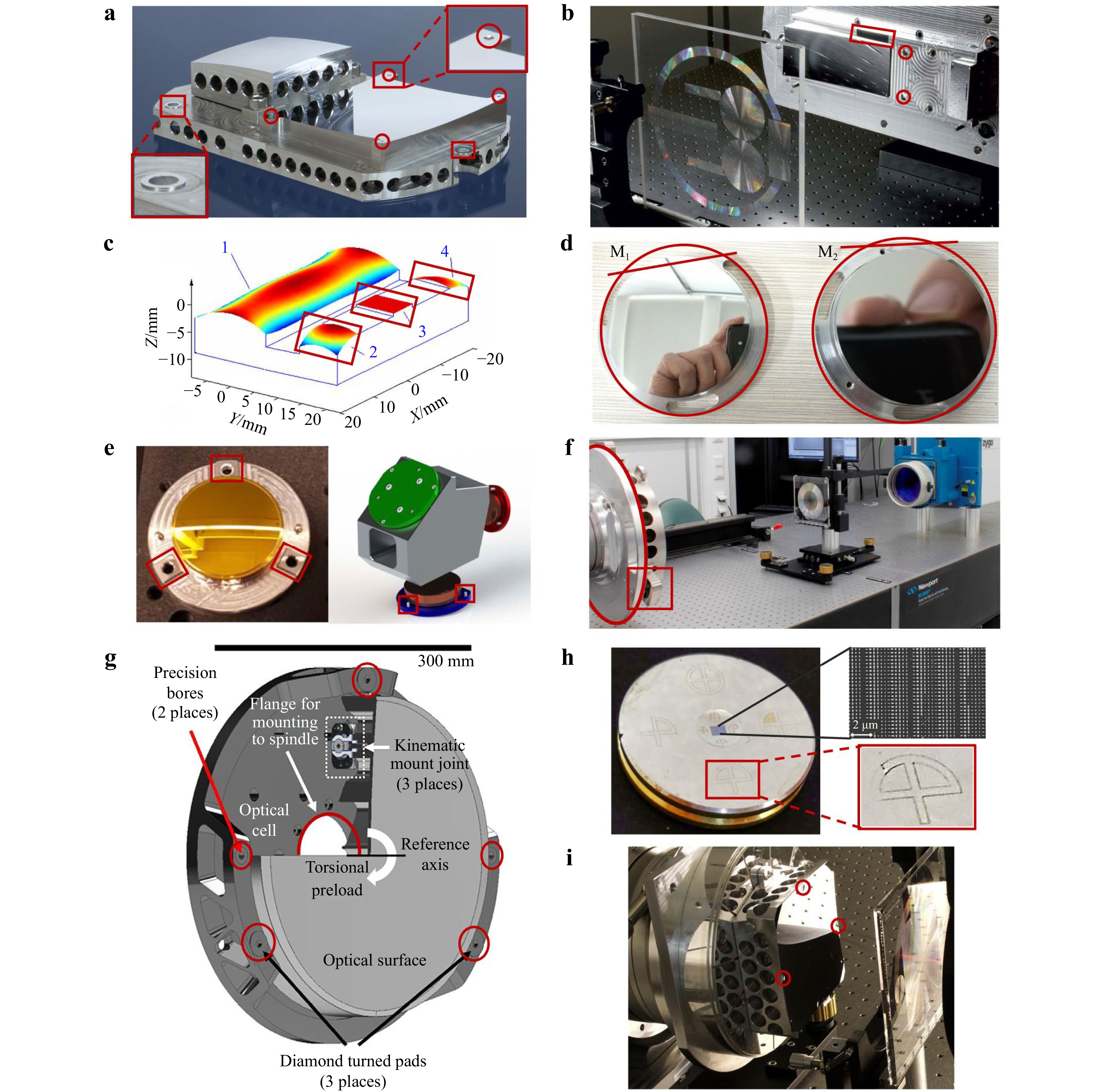
Fig. 1 Examples of freeform optical systems using various types of reference structures (RS). The RS visible on the images are highlighted with red boxes and circles. a Folded Korsch telescope with spheres and coupling interfaces for RS10. b Four-mirror afocal telescope with concave spheres and flats for RS25. c F-theta laser scanner lens with two spheres and a flat RS20. d Two-mirror freeform imaging telescope with clocking flat and concentric ring RS32. e LWIR freeform imager using raised flat pads with slots and dowel pins as coupling interface RS3. f 300 mm diameter off-axis aspheric mirror using a concentric groove and coupling interface RS on a mounting plate22. g Snap-together kinematic freeform mirror mount using a variety of RS types including precision bores, raised pads, and a flange28. h A metaform imager using scribe line RS for the alignment of a conformal metasurface and a toroidal freeform substrate31. i 108 mm diameter freeform mirror with concave spheres as RS23.
System/Application Metrology Type Source Folded Korsch telescope Panasonic UA35-5 CMM Ref. 10 Four-mirror afocal telescope Panasonic UA35-5 CMM Ref. 25 F-theta laser scanner lens Form Talysurf PGI 1240 CMM Ref. 20 Two mirror freeform imaging telescope Custom CGH Ref. 32 LWIR freeform imager Interferometric near-null test Ref. 3 300 mm diam. off-axis aspheric mirror Custom CGH Ref. 22 Kinematic freeform mirror mount N/A Ref. 28 Toroid metaform mirror UltraSurf 5x 400 CMM Ref. 31 108 mm diameter freeform mirror Panasonic UA35-5 and CGH Ref. 23 Table 1. The metrology types used for the systems shown in Fig. 1.
The studies from the literature provided insights into how RS are used in research and low-volume freeform manufacturing. To complement the literature survey and gain an understanding of the industry perspective on the problem, we developed and distributed a questionnaire on RS. The full list of questions is provided in the Supplementary Materials for reference. We collected feedback from five optics companies with specializations spanning optical fabrication, metrology, design software, tool development, and system integration. Based on the compiled information from both surveys, we developed a list of qualitative requirements that RS should satisfy.
Primarily, the set of RS used in the registration process of an optical component will define a complete CS by constraining the component in all six DoFs. Each RS must have assigned registration methods for the various steps in the process chain. Furthermore, it is important to make each RS large enough and accessible by its assigned registration method. The aim is to use each RS for registration in all steps of the manufacturing process. If this is not possible, multiple sets of RS can be used, but one set must be chosen as the parent RS set, and the location of each other RS must be clearly defined in the CS of the parent set. Finally, the RS must be manufacturable and measurable within predefined tolerances, preferably by the same methods used for the optical surfaces and ideally in the same setup and fabrication/measurement cycle.
The manufacturing tolerances of the RS are best defined via a full system misalignment error budget to ensure that each optical component can be properly aligned (within the system tolerances provided by the optical and mechanical designers) via the chosen registration methods. The surface form tolerances of each RS are the most critical, as indicated by multiple industry survey participants. This is because form errors in the RS can result in an unpredictable component misalignment. A rule of thumb is to have all the surface form tolerances of RS equal to or smaller than the component misalignment tolerances. However, in general, the relative physical extent of the RS in respect to the freeform surfaces should also be considered as form errors for smaller, more localized RS can have lower impact on the total component misalignment.
The position and orientation tolerances of the RS are next in order of importance. Errors in the relative position and orientation of the RS will result in deterministic component misalignment. For example, if a given RS is used to constrain the position of a component along a given axis, then the position misalignment of the RS along that axis will result in an equivalent misalignment for the optical component. Therefore, the misalignment of the RS can be identified during the RS metrology and compensated for at any subsequent component registration. Finally, the surface roughness of the RS has the lowest impact on the component misalignment. If a RS has a sufficiently large area, then the surface roughness can be compensated for by collecting more surface data during the registration of the RS.
It is critical to develop a plan early in the manufacturing process to guarantee that the RS of the freeform optical components in a system satisfy the qualitative requirements above. We refer to this onward as the “RS plan” as we discuss the tools and methodologies we have developed towards an RS-enabled freeform manufacturing. Establishing the RS plan requires concurrent engineering between the design, fabrication, metrology, and assembly teams. This can be challenging, especially in scenarios where these teams are not collocated, potentially resulting in inconsistencies in the final plan due to human error and miscommunication. To address these challenges, we have implemented an automated tool that can assist in the building and execution of the RS plan. The main function of the tool is the automatic generation of high-definition CAD models, in standard formats such as STEP or IGES, of freeform components directly from an optical design file. These CAD models contain both the freeform optical surfaces and any required RS. As most optical manufacturing and metrology machines can import STEPS and IGES files natively, the CAD models can provide a common CS defined by the RS throughout the entire manufacturing process chain.
The current implementation of the tool is written in Python and uses the Python API of FreeCAD – an open-source general-purpose parametric 3D CAD modeler. The overall CAD tool workflow is shown in Fig. 2. The tool converts freeform surfaces defined in an optical design software to NURBS with arbitrary precision. A higher precision is achieved by increasing the number of splines used. In most freeform parts considered to date, the splines have been distributed uniformly over the aperture of the freeform surfaces. However, the number of total splines, and hence the overall model size, can be decreased by leveraging a non-uniform distribution of the splines based on local slope and curvature33. Additionally, the software can generate various RS including flats, cylinder outside diameter (OD), and hemispheres. The types and specifications of RS are provided via user-defined custom parameters, but some defaults are also implemented as a starting point. Additional details about the software features and the workflow are described in the Methods Section.
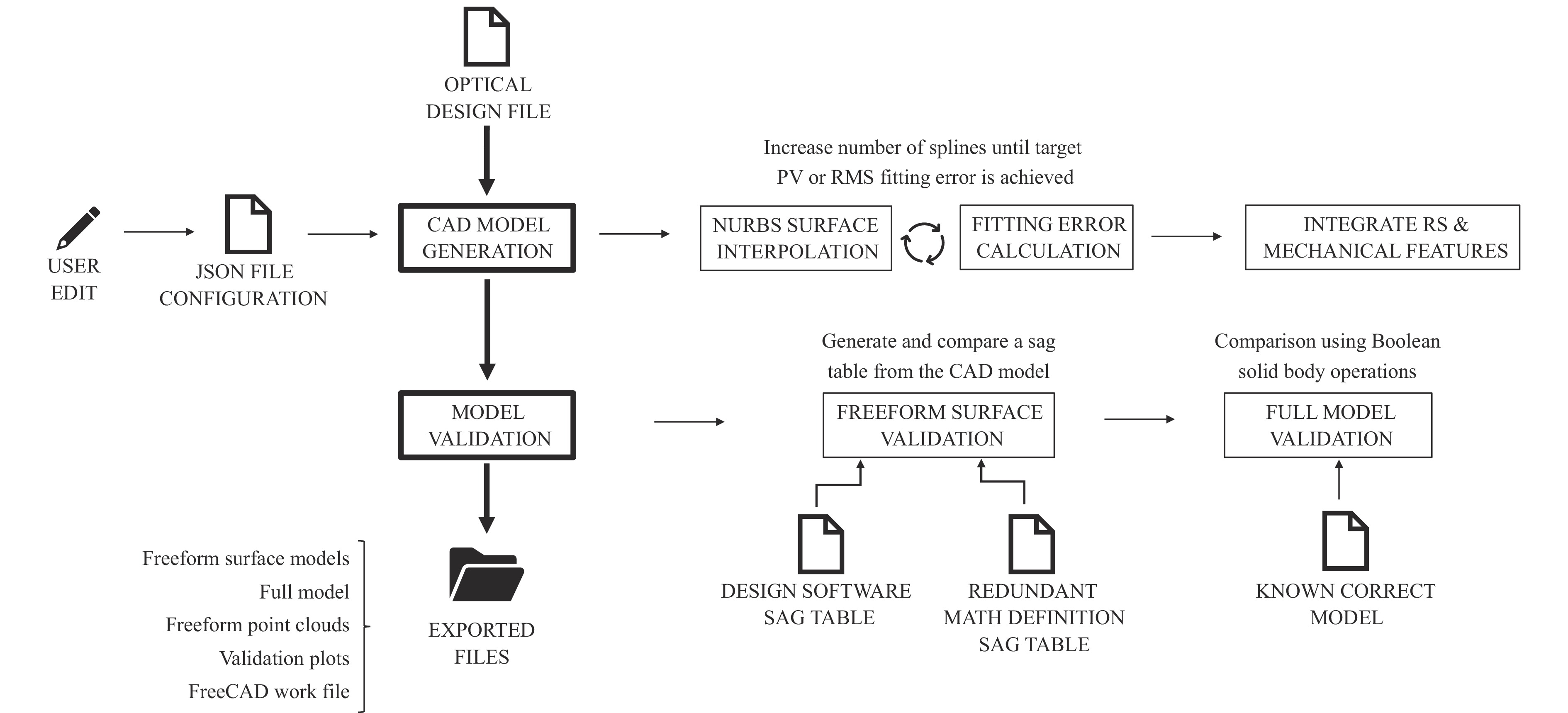
Fig. 2 CAD tool general workflow and features.
We experimentally validated the CAD tool by generating a model of a toroidal freeform mirror (Fig. 3a) and using it to fabricate and measure the mirror shown in Fig. 3b. The measurements were performed by registering the part in the metrology machine (UltraSurf 5x 400 CMM) using the sag flat, the X clocking flat, and the OD as RS. The surface form error averaged over three measurements and the per point range deviation between measurements are evaluated in the CS defined by these RS and the results are shown in Fig. 3c. The peak-to-valley (PV) surface form error is 350 nm or ~λ/2 at 633 nm. The per point range deviation is close to zero around x = 0 but increases along the positive and negative X direction, indicating the difference between the individual measurements can be accounted for by a varying amount of tilt. An additional analysis of this tilt is presented in the Supplementary Materials. As discussed earlier, a good rule of thumb we derived from the industry survey is that the surface form of the RS will limit the alignment precision of the optical component. Thus, the varying amount of tilt between the three measurements can be explained by the residual form error in the RS which was measured to be ~500 nm PV. Notably, this PV also matches well with the maximum per point range deviation shown in Fig. 3c further indicating that the uncertainty in the relative orientation/position of the freeform optics in respect to the RS is limited by the surface quality of the RS.
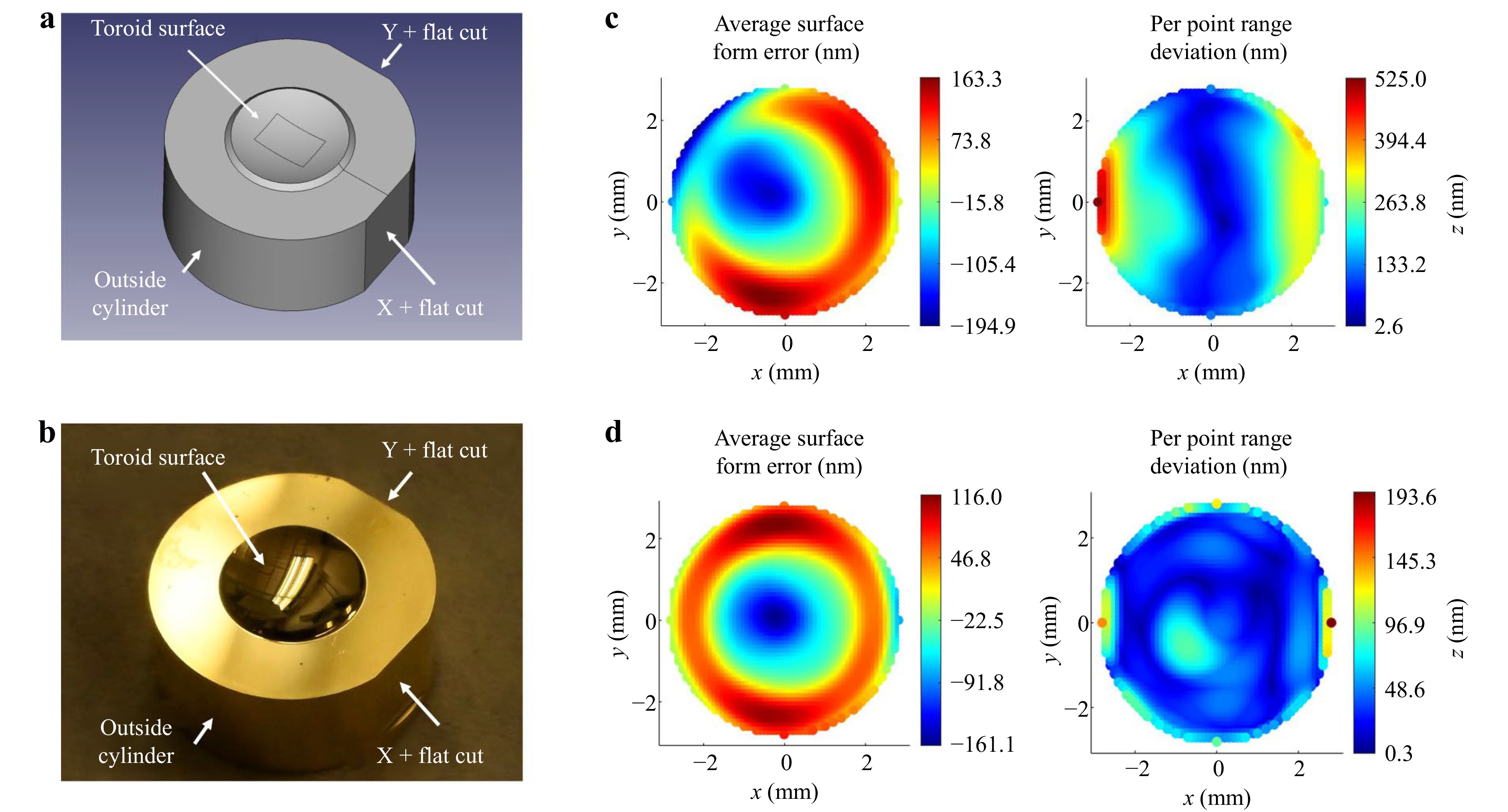
Fig. 3 Manufacturing and testing a toroidal mirror using an automatically generated CAD model. a A labeled model of the freeform component generated by the CAD tool. The model includes the toroidal freeform surface, three orthogonal flat datums (the X and Y clocking flats and the top sag flat), and a cylindrical OD as RS. The rectangular area in the toroid’s center corresponds to the optical component’s clear aperture31. b A labeled photo of the manufactured toroid mirror matching the CAD model. c, d The measured surface form error averaged over three measurements and the per point range deviation between measurements (in nm) in respect to the RS CS (c) and the local nominal surface CS (d).
To decouple the form error of the freeform surface from the alignment and positional errors in respect to the RS we also performed RBR to the nominal surface description. The resulting average surface form error in respect to the local freeform surface CS and the corresponding per point range deviation are shown in Fig. 3d. The PV of the form error was reduced to 280 nm, with the majority of the residual error being power. The per point range deviation was also reduced, with the highest values of up to ~200 nm at the far edges of the part. Over most of the clear aperture the range deviation is less than 80 nm. It should also be noted that the expected uncertainty of the used metrology platform is ~200 nm which is on the same magnitude as the residual form error making repeatability between measurements more challenging.
This experiment validates the use of the CAD tool in a complete design to manufacturing process chain. It also highlights the need for further understanding of the relationship between the quality of the RS and the alignment tolerances of the freeform optical components. For a full optical system, it is therefore essential to perform a misalignment error budget to determine the quantitative tolerances of the RS. This error budget will ideally be automatically performed simultaneously with the model generation based on the system tolerances in the optical design file. However, the industry and literature surveys we conducted did not quantify the misalignment expected when using various combinations of RS and registration methods – information that is essential for the error budget.
We have thus developed an experimental framework for evaluating these metrics using the freeform test component and matching mounting base shown in Fig. 4. The test component has an OD of 36 mm and clear aperture of 16 mm. The freeform surface is an anamorphic asphere with a maximum freeform departure from a best-fit sphere of ~70 μm. The component geometry includes various subsets of RS that each define a CS. The included RS are flats, cylinders, and spheres – the RS types most commonly used in the literature and industry survey. Additional details for the component features and the full freeform surface description for this component are described in the Methods Section. A technical drawing using geometric dimensioning and tolerancing (GD&T) is also provided in the Supplementary Materials.
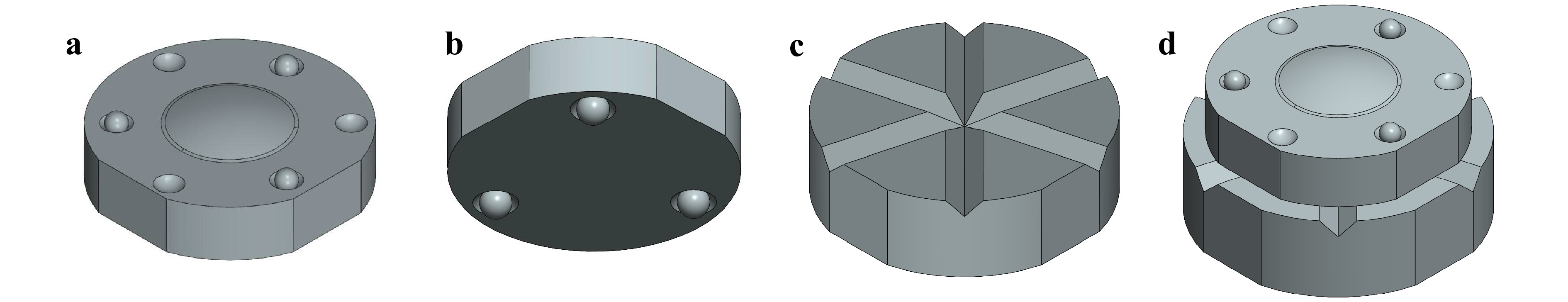
Fig. 4 Freeform test component and matching mounting base for use in the developed experimental framework. a, b top and bottom isometric view of the test component consisting of (a) an anamorphic asphere with three flat RS, a cylindrical OD RS, a set of three concave spherical RS, a set of three convex spherical RS, and (b) a set of three convex mounting spheres. c A mounting base with three V-groove interfaces matching the three mounting spheres on the test component. d The test component and the mounting base coupled together.
The proposed experimental procedure shown in Fig. 5 has three distinct phases evaluating 1) the repeatability and intermediate precision of the registration using each subset of RS, 2) the as-built misalignment between the freeform surfaces and the RS, and 3) the mounting intermediate precision enabled by the sphere and V-groove coupling interfaces. In Phase 1, the repeatability is measured by registering the test RS in the CS of the parent RS a total of N times during a single mounting of the test component. The intermediate precision is measured by remounting the test component M times and performing N registrations for each mounting. In Phase 2, the misalignment between the freeform surface and the RS is evaluated by independently registering the freeform surface and the test set of RS to the CS of the parent RS. In Phase 3, to evaluate the intermediate precision of the component alignment, the concave sphere coupling interfaces on the test component are first measured in the CS of the parent RS, then the grooves are measured in the CS of a set of three flat RS on the mount, and finally the flat RS on the mount are measured in the CS of the parent RS.
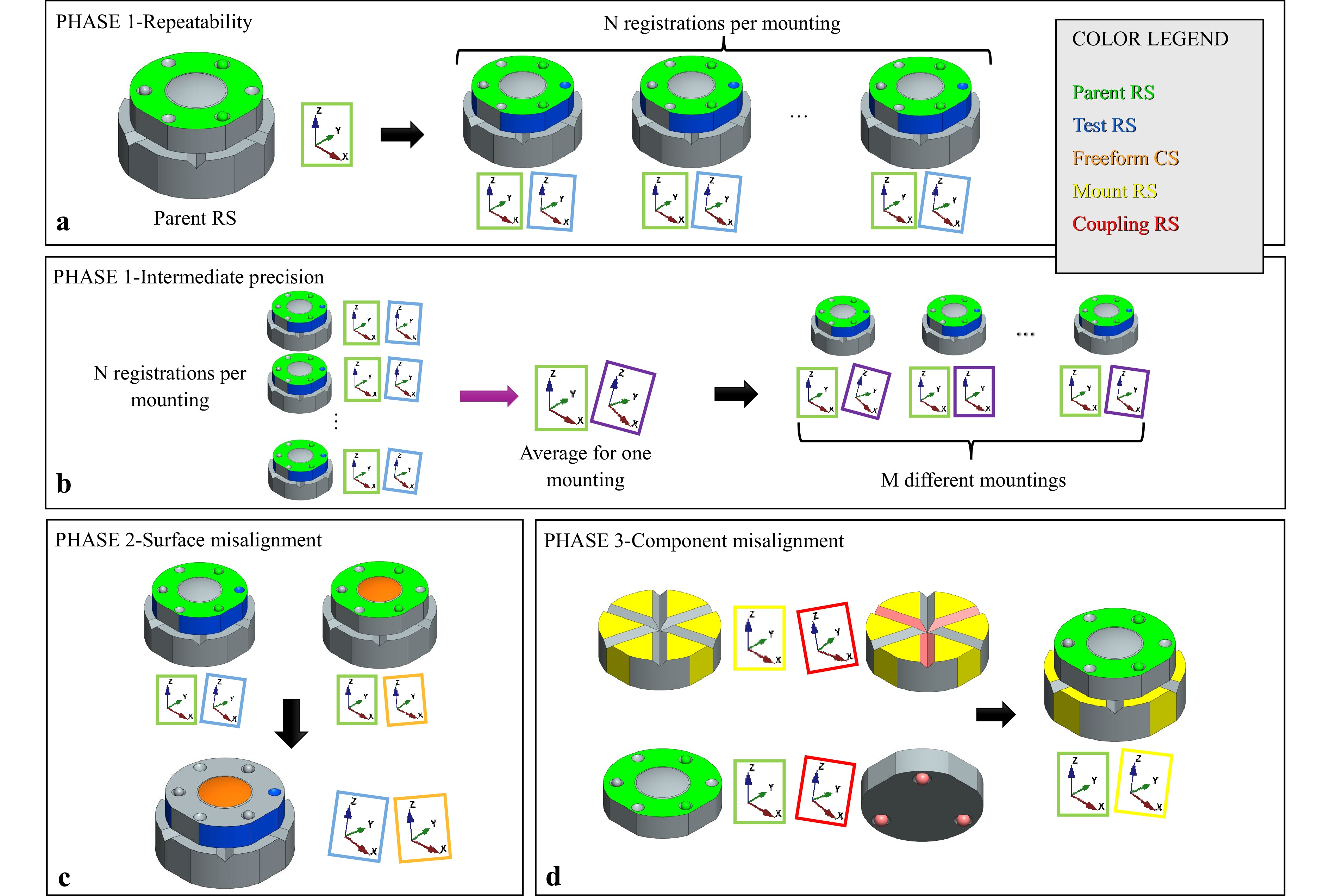
Fig. 5 An illustration of the three-phase experiment framework. a, b Phase 1 of the experiment evaluating (a) the repeatability and (b) the intermediate precision of the component registration using various sets of test RS. The parent RS shown in green are the top flat and two of the convex spheres on the top surface. An example test set of RS is shown in blue − a concave sphere, the side flat, and the cylindrical OD. c Phase 2 of the experiment evaluating the misalignment between the as-built freeform surface (shown in orange) and the chosen test set of RS. d Phase 3 of the experiment evaluating the surface form of the coupling interfaces (shown in red) and the alignment intermediate precision of the mounting process. The xyz insets in all phases illustrate CSs defined by different RS subsets and in different registration cycles. All but the purple-framed insets are color-matched to their corresponding RS subsets as shown in the legend. The purple-framed insets correspond to CSs that are averages of the blue-framed insets for a particular remounting of the test component. Two insets with different frame colors next to each other imply that the second coordinate system is registered to the first one.
Here, for the intermediate precision condition34, we focus on the variability between different component mountings. However, the experiment framework can also be used for other intermediate conditions such as change of operator or change of machine. If measuring the component on different metrology machines in different laboratories, the developed framework can also provide reproducibility. Furthermore, this experiment is agnostic of the choice of a metrology platform. The only requirements are that the metrology platform must be capable of registering the component in the machine using the parent RS and both the freeform surface and the test RS must be measurable. Finally, while Fig. 5 illustrates the experimental framework using the anamorphic asphere test component from Fig. 4, the experiment design is general and can be adapted to other types of freeform surfaces. Thus, in the most general case this experimental framework can provide quantitative data for the alignment reproducibility enabled by a given type of RS for any combination of a freeform optical component and a metrology platform.
In conclusion, we have identified a path towards more efficient freeform optics manufacturing reliant on automation and efficient use of RS. By combining knowledge from both literature and industry, we have established a set of qualitative requirements for effective RS. We have developed and experimentally validated an automated CAD tool and have designed a general experimental framework to evaluate the quantitative requirements for effective RS. We also used the validated CAD tool to design and prepare models and technical drawings for a freeform test component with the RS types most used in literature and industry. Next, manufacturing the proposed test component and performing the three-phase experiment will provide the data required to implement an automated error budget evaluation into the CAD tool. We also anticipate that in general the choice of effective RS may be dependent on the shape of the specific freeform surfaces and other optomechanical design constraints. Therefore, it is not possible to use a single process chain for all applications. However, the tools and methodologies we have developed here are general and can be adapted to test other scenarios and types of freeform surfaces in the future. Ultimately, we are establishing the best practices for scalable, automated, and application specific freeform manufacturing process chains – not unlike the ones standard in other challenging domains such as silicon chip manufacturing.
-
The main input for model generation using the CAD tool is the optical design file and the component number. The component number is typically defined by the user by providing the index of a surface from the optical design file. The software parses the optical design file and smartly identifies if the indicated surface is a mirror or part of a larger refractive component with multiple surfaces. The software then generates a configuration file in a JavaScript Object Notation (JSON) format. The JSON lists key parameters extracted from the optical design file including the clear aperture, the outside edge aperture (if it is defined), and the shape of the apertures (circular or rectangular). The JSON also includes some sensible defaults for the RS and other mechanical features. This includes the thickness of the component if it is a mirror, the position of the sag flats, and the position of an X and a Y flat if the edge aperture is circular. The user can modify this file at time of generation or provide it in advance together with the optical design file. All values extracted from the optical design file and the additional default parameters for the RS can be overwritten by the user. The user can additionally specify the relative positions and the dimensions of spherical RS (concave or convex) positioned on either of the sag flats. The radius of a transition area between the freeform surfaces and the sag flats can also be specified. Finally, the user can specify the maximum allowable NURBS fitting error for the optical surfaces as an RMS or a PV. The default is 2 nm RMS.
The freeform surface models are generated by performing a NURBS global interpolation35 to generate a 2D spline surface that is fitted to the nominal surface descriptions extracted from the optical design file. We are using cubic B-splines for the NURBS surfaces. Once each NURBS is generated, a point cloud sampling the NURBS surface is used to evaluate the fitting error. If the resulting error is higher than the maximum specified in the JSON configuration file, the number of splines is increased, and the fitting is performed again. This process is repeated until the target fitting error is achieved. Each freeform NURBS surface is then saved as an IGES file. All of this is done in Python and the IGES files are written manually to guarantee the proper storing of the NURBS control points, knots, and weights in double-precision.
Once the freeform surfaces are generated, they are imported in FreeCAD using the FreeCAD Python API. The full model with the RS is then generated as a solid using the API and the parameters specified in the JSON configuration file. The final model is then saved and exported as both an IGES and STEP file using FreeCAD. It should be noted that we verified that the initial freeform NURBS specified in the manually written IGES files are preserved when the final model is exported by FreeCAD. All the control points, knots, and weights are saved with the same number of significant digits as in the original IGES files. That being said, from our industry survey we have anecdotally confirmed that some precision in the NURBS surfaces can be lost when importing and exporting IGES and STEP files between different software. To provide an added level of confidence in the models generated by the CAD tool we can also perform some redundant validation. We have implemented two types of redundant validation – point cloud-based validation of the individual freeform surfaces and comparison against a known correct model using Boolean operations between solids.
For the former validation, we first generate a point cloud for each freeform surface by finding the intersection points of an array of parallel lines with the corresponding NURBS surface. This is done using the FreeCAD API. We then generate a point cloud sharing the same XY coordinates using a redundant source. This source can be either the optical design software or an independent Python script with the nominal mathematical formula for the freeform surface being tested. The point cloud generated from the CAD model is then compared with the point clouds generated from each of the redundant sources and the final error is saved and exported as a 2D surface plot for later use.
For validating the full models with the RS and mechanical features we have implemented the ability to compare a generated model (A) with another model provided with the user (B). This comparison is done by performing Boolean subtraction between the two solids. We perform both A-B and B-A subtraction and evaluate the volume of each difference. If both differences are zero, then the models are considered identical. If they are not, we save their differences as a new body in a FreeCAD file that can be inspected manually. While this comparison does not directly verify the surface properties of each of the RS when generating a brand-new model (as a preexisting “correct” model is needed), it does provide useful validation in few scenarios. One scenario is importing a generated model in another third-party CAD software, making modifications to it and then exporting it. The modified model can then be compared with the originally generated model to confirm if the differences can be fully accounted for by the intended changes performed in the third-party software. This scenario is useful when additional features not available in the CAD tool need to be added to a model for mechanical or manufacturing reasons while still maintaining the same accuracy and relative position of the freeform surfaces. Another scenario is for test-driven development of the CAD tool. We have created a library of example scenarios where each scenario has a predefined optical design file, a JSON configuration file, and a CAD model that we have manually verified to be correct. When adding new features to the CAD tool we periodically run all the scenarios and test that the models generated using the new software version match the previously generated models.
-
To validate the developed CAD tool, we generated a model of a toroid used as a freeform substrate in the manufacturing of a metaform imager31. The toroid surface sag is defined as
$$ {\mathrm{z}}_{toroid}(x,y)=\sqrt{{\left({R}_{y}-{R}_{x}-\sqrt{{R}_{x}^{2}-{x}^{2}}\right)}^{2}-{y}^{2}}+{R}_{y} $$ (1) where Rx = −8.24 mm and Ry = −7.78 mm are the two radii of curvature of the toroid.
The model shown in Fig. 3a was generated automatically from the optical design of the metaform imager and a set of user-defined parameters for the three orthogonal flats and the cylindrical OD RS. The toroid clear aperture diameter is 6 mm. The OD cylinder diameter is 12.6 mm. The height of the part measured as the distance from the back flat to the top flat is 5 mm. The X and Y clocking flats are cut at 300 µm from the edge of the OD. For this specific example, the surface description, the OD diameter, and the preliminary rectangular clear aperture of 2 mm × 1.5 mm are loaded directly from the optical design file at model generation time. The preliminary aperture size and shape are then overwritten by the final 6 mm circular aperture using a configuration JSON file that can be created by the user in advance or modified at the beginning of model generation. Other parameters not defined in the optical design file such as the height and the cut depths for the X and Y clocking flat are also specified by the user via the JSON configuration file. The generated CAD model was then used to fabricate and measure the component.
-
The part was fabricated using a four-axis Moore Nanotech 250 UPLv2 diamond turning lathe. The CAD model imported as a STEP file was directly compatible with NanoCam − the diamond turning machine software. The used diamond lathe is a three-axis (X, C, and Z) slow tool servo. The freeform surface and all the RS were manufactured together to preserve the same CS to best effort. The brass blank was first mounted in the machine with its back surface laying on a diamond turned vacuum chuck that is perpendicular to the machine Z axis. The OD and the X and Y flats were then cut using the X and C axes. Finally, the top flat and the freeform were cut using the Z and C axes.
-
The manufactured toroid was measured on an UltraSurf 5x 400 − a 5-axis non-contact coordinate measuring machine (CMM). The CAD model as a STEP file was imported directly into the UltraSurf software. We performed three measurements with the part remounted and reregistered before each measurement. The registration was done using the top flat, one of the side flats (labeled as X flat in Fig. 3a, b, and the OD as RS. The used RS were measured together with the freeform optics at each reregistration. Due to the orientation that the X and Y flats were cut at, they have a residual form error of ~500 nm PV. This can be improved in the future by using a diamond lathe with an additional Y axis and a dedicated milling lathe sharing the same machine CS as the diamond lathe. The Y flat was manufactured to provide another possible CS using the three flats. That CS was not used during the presented measurements as the CS formed by the top flat, the X flat, and the OD provided repeatability between measurements within the uncertainty of the UltraSurf CMM.
-
The freeform test component is a one-inch diameter anamorphic asphere (shown in Fig. 4a). The anamorphic asphere is defined as
$$ {\mathrm{z}}_{aa}\left(x,y\right)=\frac{{{c}}_{{x}}{x}^{2}+{c}_{y}{y}^{2}}{1+\sqrt{1-{c}_{x}^{2}{x}^{2}-{{c}_{y}^{2}y}^{2}}}+A{\left({x}^{2}+{y}^{2}\right)}^{2} $$ (2) where $ {{c}}_{{x}}=1/{R}_{x} $ and $ {{c}}_{{x}}=1/{R}_{x} $ are the curvature of the surface in x and y, Rx = 18.5 mm and Ry = 19.0 mm are the corresponding radii of curvature, and A = −0.00005 is an aspheric coefficient. The radii of curvature and the aspheric terms were chosen to achieve a moderately high PV freeform departure from the best-fit sphere (~100 μm over the clear aperture), thus providing a more challenging scenario for manufacturing and metrology. This surface description shares similarity with a toroid with an added aspheric term.
A toroid such as the one shown in Fig. 3 is a surface of revolution and thus has an intrinsic rotational invariance. Since the axis of rotational invariance is not along the axis perpendicular to the sag face, a toroid is often considered a freeform depending on the application and the metrology and manufacturing methods. However, in the strictest definition, a freeform optical surface is defined as a surface with no axis of rotational invariance within or beyond the part1. By using an anamorphic asphere we satisfy this stricter definition, making the test component more representative of a general freeform surface. This decision was also informed by the feedback from the industry survey.
The test component shown in Fig. 4 is designed to be manufactured from nickel-phosphorus using diamond turning. The clear aperture of the component is 16 mm in diameter, and the edge aperture is 28 mm in diameter. The two clocking flats are cut 1 mm from the edge of the OD. The opening of the concave spherical RS lay on a 30 mm diameter circle concentric to the optical surface clear aperture. The geometry of the top face is designed with three truncated conic pockets laying on another concentric circle with a diameter of 28mm. A set of three 1.5 mm grade 10 silicon carbide balls must be glued to serve as the convex sphere RS.
As shown in Fig. 4c the component can be mounted using a set of three spheres as coupling interfaces and a mounting base with three matching V-grooves (Fig. 4b). The sphere coupling interfaces will be 2 mm grade 10 silicon carbide balls glued into truncated conic pockets. We will use the top flat and two of the convex spheres on the top surfaces as the parent set of RS during fabrication and metrology. The selected RS provide an unambiguous CS. A set of RS defines a unique CS if they unambiguously define a plane, a line (parallel to the plane), and a point. The top flat is a plane, the centers of curvature of the chosen convex spheres form a line, and one of the two centers can be chosen as the point. The use of two of the convex spheres as parent RS is why we decided to glue high-precision silicon carbide balls instead of diamond turning the convex spheres as part of a monolith geometry. We expect the silicon carbide balls to provide better surface form quality, which is essential for parent RS. When using the CAD tool the model for this component was generated with both the top and bottom set of convex spheres as part of a monolith geometry. The geometry was then manually modified in another third-party CAD software to integrate the truncated conic pockets and individual balls. The final exported model was then validated against the original monolith geometry exported by the CAD tool to verify that the only change was the convex sphere RS.
-
The planned experimental procedure has three distinct phases evaluating various factors that contribute to the overall freeform surface and component alignment using the provided sets of RS for registration. In the first phase, we evaluate the repeatability of the registration using each subset of RS by mounting the test piece in the metrology machine and measuring each RS in the CS of the parent RS multiple times. We then evaluate the intermediate precision of the registration process by removing the test piece, remounting it, and measuring it again multiple times as illustrated in Fig. 5. While this phase focuses on the registration of the RS in each measurement cycle, we also measure the freeform surface itself. We then use this data in the second phase of the experiment, where we evaluate the as-built misalignment of the freeform surface with respect to the various subsets of RS by performing RBR of the measured freeform data to the nominal toroid description. This provides us with the internal CS of the freeform surface, which we can then compare to the CS of the parent RS. In the final third stage of the experiment, we evaluate the intermediate precision of the alignment between the test piece and the mounting base. We first measure the V-grooves in the CS defined by three plane RS on the mount and the mounting spheres in the CS of parent RS as illustrated in Fig. 5d. We then mount the test piece on the mounting base multiple times and, each time, measure the three flat RS on the mount in the CS of the parent RS. The final step of the planned experiment is to draw a correlation between the surface form quality of the coupling interfaces and the alignment repeatability of the mounting process using those coupling interfaces.
-
This research was supported by the industry members of the Center for Freeform Optics (CeFO) and the National Science Foundation (IIP-1822049 and IIP-1822026, EEC-2310640, EEC-2310681). We thank Mike Pomerantz and Monroe Community College (MCC) for fabricating the toroid test piece used to validate the CAD tool, and Anjeli Estrada Alvarez for assisting with the technical drawings for the anamorphic asphere test component.
Towards automated manufacturing process chains for freeform optics with effective reference structures
- Light: Advanced Manufacturing , Article number: (2025)
- Received: 06 December 2024
- Revised: 26 July 2025
- Accepted: 30 July 2025 Published online: 29 September 2025
doi: https://doi.org/10.37188/lam.2025.061
Research Summary
Relational freeform manufacturing: Geometric landmarks enable making complex optics
Advanced geometric features can be used to locate freeform optical elements in 3D space during system manufacturing, testing, and assembly, enabling the production of compact imagers and brighter and more uniform illuminators. Freeform optics have no axis of rotational invariance, allowing them to serve more functions in imaging and illumination systems at the cost of higher manufacturing complexity. Daniel K. Nikolov from the University of Rochester and collaborators report developments towards scalable, automated, and application specific freeform manufacturing using reference structures – advanced geometric features providing a common relative position for the freeform optical elements. The team establishes the best practices for the effective use of reference structures at every stage of the freeform manufacturing process and demonstrates an automated CAD tool and an experimental framework for application specific implementation of these practices.
Rights and permissions
Open Access This article is licensed under a Creative Commons Attribution 4.0 International License, which permits use, sharing, adaptation, distribution and reproduction in any medium or format, as long as you give appropriate credit to the original author(s) and the source, provide a link to the Creative Commons license, and indicate if changes were made. The images or other third party material in this article are included in the article′s Creative Commons license, unless indicated otherwise in a credit line to the material. If material is not included in the article′s Creative Commons license and your intended use is not permitted by statutory regulation or exceeds the permitted use, you will need to obtain permission directly from the copyright holder. To view a copy of this license, visit http://creativecommons.org/licenses/by/4.0/.

 DownLoad: