


-
The emergence of Additive Manufacturing (AM), commonly known as 3D Printing, represented a breakthrough in the field of product development1,2. Although AM offers numerous advantages, current techniques still face several challenges. One of these is the process of transforming digital data into printable segments, usually in the form of cross-sectional layers, which can affect both the surface quality and the mechanical properties of the final printed part3. Compared to other AM techniques, such as fused deposition modeling (FDM), direct ink writing (DIW), and selective laser sintering (SLS), vat photopolymerization (VPP) stands out as a relatively fast fabrication method known for its excellent resolution4,5. It operates by selectively exposing specific points in 3D space within a material to light, initiating photochemical reactions that create physical objects6. Current research in VPP focuses on addressing limitations such as layer stair-step effects and anisotropic mechanical properties while striving to achieve fabrication speeds comparable to injection molding7. Consequently, VPP has emerged as one of the most promising technologies for producing parts through a single, unified process, offering superior structural integrity and surface quality8–12. Moreover, Photopolymerization-based 3D printing methods have been extensively explored for applications in biomedical engineering, aerospace, and high-performance manufacturing. Recent reviews have highlighted their use in controlled drug delivery systems13, also in advanced functional materials for aerospace and soft robotics14. To accelerate production speed, two primary approaches have been proposed: continuous VPP methods and volumetric printing techniques15–17.
In continuous VPP technologies, the build platform moves continuously during the photopolymerization process, which occurs in the space between the cured structure and the bottom of the resin vat18,19. A prominent example of this approach is continuous liquid interface production (CLIP), which utilizes an oxygen-permeable window to create a “dead zone” due to the oxygen’s inhibitory effect on free-radical photopolymerization20,21. For instance, Mirkin’s group developed the High-Area Rapid Printing (HARP) method, where an immiscible fluorinated oil flows at the vat’s bottom22. Photopolymerization occurs continuously above the flowing oil, which dissipates heat efficiently, preventing overheating in the curing area. However, CLIP struggles with scalability due to increased resin refill time for larger cross-sections. Another example is mask video projection-based stereolithography (MVP-SL), which combines continuous lateral motion between the build platform and a resin tank coated with polydimethylsiloxane (PDMS). This motion generates a dead zone and actively feeds resin into the light exposure area23. Despite these advancements, the core principle of continuous VPP processes remains the sequential stacking of 2D patterns, which fundamentally limits the production speed and scalability of VPP techniques.
Unlike continuous VPP methods, volumetric AM (VAM) printing techniques directly and swiftly cure structures within the resin vat without the need for a building platform, eliminating the necessity for resin refilling during the printing process24,25. For instance, computed axial lithography (CAL), proposed by Brett K. et al., transmits optical energy to the material volume by projecting a series of 2D pictures from various angles26. The light energy of each projection emanates from a specific angle, and the superposition of exposures from several angles produces adequate energy dosages at targeted voxels, therefore solidifying materials into intended structures. This process is inherently capable of large volume fabrication, but the resolution is limited to submillimeter features. Furthermore, holographic VAM employs three orthogonal beams that intersect within the liquid photopolymer, with the threshold for photopolymerization being met solely through the combination of these three laser beams27,28. In this method, the curing of the structure is accomplished simultaneously within 1 to 25 secs exposure with 10 to 100 µm resolutions. Nonetheless, the complexity of the geometry of printed products is constrained, as all three orthogonal beams are derived from the deflection of a single holographically generated image29. Moreover, the fabrication capacity of this approach is limited because of the attenuation effect along the optical path as the beam traverses the liquid photopolymer without inducing cure. Comparably, Xolography represents a distinct VAM technique that employs the intersection of beams during its fabrication process, which utilizes two orthogonal beams of varying wavelengths due to the application of a dual color PI in the resin preparation process30,31. Free radical photopolymerization is initiated solely upon exposure to light at a wavelength of 375 nm and visible light within the range of 450 nm to 700 nm. The printing process involves focusing a diverging 375 nm laser line into the center of the print volume to create a light sheet. Also, a digital light projector is then employed to project patterns onto this light sheet, facilitating photopolymerization and enabling volumetric printing in a linear manner32. Although the existing VAM techniques have significantly enhanced the fabrication speed of VPP methods, there remain limitations and challenges in the current approaches which need to be resolved.
To achieve faster fabrication speeds and enable multi-scale 3D printing in a single process, this study introduces a novel linear volumetric printing technology called Light-Initiated Direct Growth (LIDG). LIDG controls the distribution of optical energy within a 3D space to initiate volumetric photopolymerization by dynamically adjusting the focus position and projected light. Drawing inspiration from natural growth processes, such as crystal formation and growth within liquids, LIDG utilizes light energy to trigger photopolymerization at the outer surface of pre-solidified regions, causing the polymerized resin to expand around the preprinted objects. This process culminates in the formation of complex 3D geometries directly within a translucent photocurable liquid polymer. To realize this innovative approach, a dynamic linear light projection strategy was developed to ensure the resin receives sufficient energy to form 3D geometries without overcuring. A detailed mathematical model was constructed to predict the printing speed, which was validated and refined through experiments. The maximum achievable fabrication capability was determined using the model, establishing the threshold light intensity required for photopolymerization. Since resin viscosity significantly influences the printing quality in the LIDG process, this study also investigated the effects of viscosity experimentally. Additionally, a model describing the distribution of optical energy in 3D space to initiate the crosslink for 3D object fabrication was developed, accounting for the optical differences between the solidified and liquid polymer phases. This enhanced the accuracy and efficiency of the LIDG process. Finally, the LIDG technique was demonstrated by fabricating structures with intricate micro-scale features and substantial macro-scale components at unprecedented speeds. This study showcases how LIDG addresses key limitations of traditional VPP methods, providing a versatile and efficient solution for producing complex objects across multiple scales in a matter of seconds.
-
This study utilized bisphenol A glycerolate (1 glycerol/phenol) diacrylate (BPAGDA, molecular weight 484.54 g/mol) and poly (ethylene glycol) diacrylate (PEGDA 700, average molecular weight 700 g/mol) sourced from Sigma-Aldrich (UK), with the Omnirad 819 photoinitiator (PI) acquired from IGM Resins (USA). BPAGDA was selected due to its high viscosity, which enhances the mechanical stability of printed structures, whereas PEGDA 700 was chosen for its effective crosslinking properties and photo-reactivity33. All materials were utilized without additional purification, and deionized water and ethanol served as cleaning agents for the post-processing of printed components. The experiments were performed in controlled laboratory conditions to maintain consistency across trials. Specifically, in a temperature-controlled environment maintained at 22 ± 1°C, with stable humidity levels of approximately 40%−50%, to minimize variations in resin viscosity and photopolymerization kinetics. Additionally, all printing processes were performed in an enclosed setup to prevent unintended curing due to ambient light exposure. Seven unique photopolymer resin formulations were developed initial investigation and previous literature and optimized for LIDG printing. Resin formulations were created by combining 40 g of resin with different weight ratios of BPAGDA to PEGDA 700 (1:2, 1:1, 5:4, 3:2, 7:4, 2:1, 3:1, and 7:1) to investigate the influence of composition on LIDG printing performance. The resin mixtures were heated to 60°C and subjected to magnetic stirring at 500 rpm for 2 hours to decrease viscosity and achieve homogeneity. The PI was omitted in material preparation for rheological assessments, and for printing trials, 0.1 wt.% of Omnirad 819 was incorporated into each formulation to enable photopolymerization. All resin mixtures were maintained in sealed containers to ensure consistency and prevent contamination during the study.
-
To investigate the impact of resin viscosity on the LIDG printing process, a comprehensive series of rheological tests were performed on the prepared resin mixtures, each with varying weight ratios of BPAGDA and PEGDA. The rheological behavior of the printing formulations was characterized using a Discovery Hybrid Rheometer HR 30 (TA Instruments) to assess the viscosity across a range of shear rates. Based on our experiments, the optimal viscosity range for achieving high-quality LIDG printing was determined to be 0.5−3.0 Pa·s at a shear rate of 10 s−1. This range ensures a balance between sufficient resin flowability for uniform material distribution and adequate mechanical stability for precise feature formation during photopolymerization, particularly for complex, multi-scale geometries.
-
Accurate mathematical models for optical energy distribution inside the resin tank particular the fabrication area require an evaluation of the attenuation and refractive properties of the printing resin. A solid polymer part with a thickness of 12.5 mm was fabricated using photopolymer resin for the measurement of the attenuation coefficient, while the liquid resin was contained in a polystyrene spectrophotometer cuvette (LAB4US). The projector PDC04-35, produced by XIAMEN ZHISEN ELECTROMECHANICAL EQUIPMENT CO., LTD, accurately simulated real printing conditions by directing a small square of light through the cuvette, thereby ensuring unobstructed passage through the liquid resin without dispersion. A digital light meter (LX1330B, Dr. Meter) was employed to quantify light intensity at different depths. The attenuation coefficients for the solidified and liquid resin were determined using the Beer-Lambert law34 (Eq. 1), offering insights into light propagation and reduction within the material. The intensity of light travelling into the printing resin can be calculated by the attenuation coefficient $ \mu $ and the depth $ z $:
$$ I\left(z\right)={I}_{0}{e}^{-\mu z} $$ (1) Furthermore, the refractive coefficient was quantified to develop an analytical model for the distribution of optical energy in photocurable resins. A custom container featuring a reflective mirror at the base was developed to accommodate both liquid and solid photopolymers. A focused beam of curing light was directed at the polymer at a 60° angle, resulting in refraction at the air-polymer interface. The reflection from the mirror, the material at a different position, excelled at a different position. The distance between the entry and exit points of the light beam, as well as the thickness of the material, was quantified. The refraction angle was derived from these measurements, and Snell’s Law35 (Eq. 2) was utilized to compute the refractive indices of the liquid and solid polymers. Where n1 and n2 are the refractive indices of the two media involved in light transmission and refraction.
$$ \frac{sin{\theta }_{1}}{sin{\theta }_{2}}=\frac{{n}_{2}}{{n}_{1}} $$ (2) -
To facilitate the ongoing functionality of the LIDG process, the resin vat was affixed to a linear stage (404XR, Parker) featuring a travel range of 150 mm, where a digital light processing (DLP) projector served as the light source. The light emitted from the projector PDC04-35 was directed through a convex lens with a 150 mm focal length (Thorlabs LA1509), specifically chosen to concentrate the projected beam and ensure uniform energy distribution at the curing interface, and the optical path was redirected from horizontal to vertical through the use of aluminum-coated mirror (50 mm × 50 mm, 3 mm thickness, 94% reflectivity at 405 nm), which ensures efficient light reflection without secondary ghost images. This optical arrangement is critical for maintaining precise light exposure, optimizing photopolymerization, and achieving high-quality prints in the LIDG process. Moreover, the light beam subsequently infiltrated the printing session that had been cured earlier, concentrating accurately on the active cured cross-section, thereby guaranteeing precise and regulated polymerization during the printing process. This configuration enables ongoing layer development while ensuring uniform energy distribution throughout the build volume.
-
There are two distinct printing strategies for the LIDG process: one without focus adjustment and another with focus light adjustment. In the no-focus light adjustment method, the resin tank remains stationary throughout the printing process, with the projection light always focused on the bottom surface of the vat. However, this approach poses challenges in controlling the growth of the cured photopolymer, leading to inaccuracies in the printed results. These issues arise because the liquid and solid photopolymer exhibit different optical properties, particularly their effective absorption coefficients, which significantly affect the optical energy distribution along the Z-axis (the direction of light transmission) (see Supporting Information Video S1). To enhance printing quality, the focus adjustment strategy was introduced. In this approach, the resin tank is continuously lowered during printing, ensuring that the projection light remains precisely focused on the interface where photopolymerization occurs, as illustrated in Fig. 1a. Unlike traditional SLA or DLP techniques, where the projection light solidifies resin only between the preprinted layer and the Teflon film, the LIDG process enables the light to penetrate through the preprinted section. This allows continuous crosslinking, facilitating the formation of complex 3D solid structures along a linear motion in the Z direction, as illustrated in Fig. 1b. In the LIDG process, the resin tank moves downward during printing, allowing the light to pass through the already solidified, transparent sections of the printed part and initiate polymerization of the resin at the growing surface. This creates the appearance of continuous structural growth driven by the projected light. Additionally, the LIDG process eliminates the need for resin refilling, significantly reducing printing time, particularly for solid structures with large cross-sectional areas (Fig. 1c).
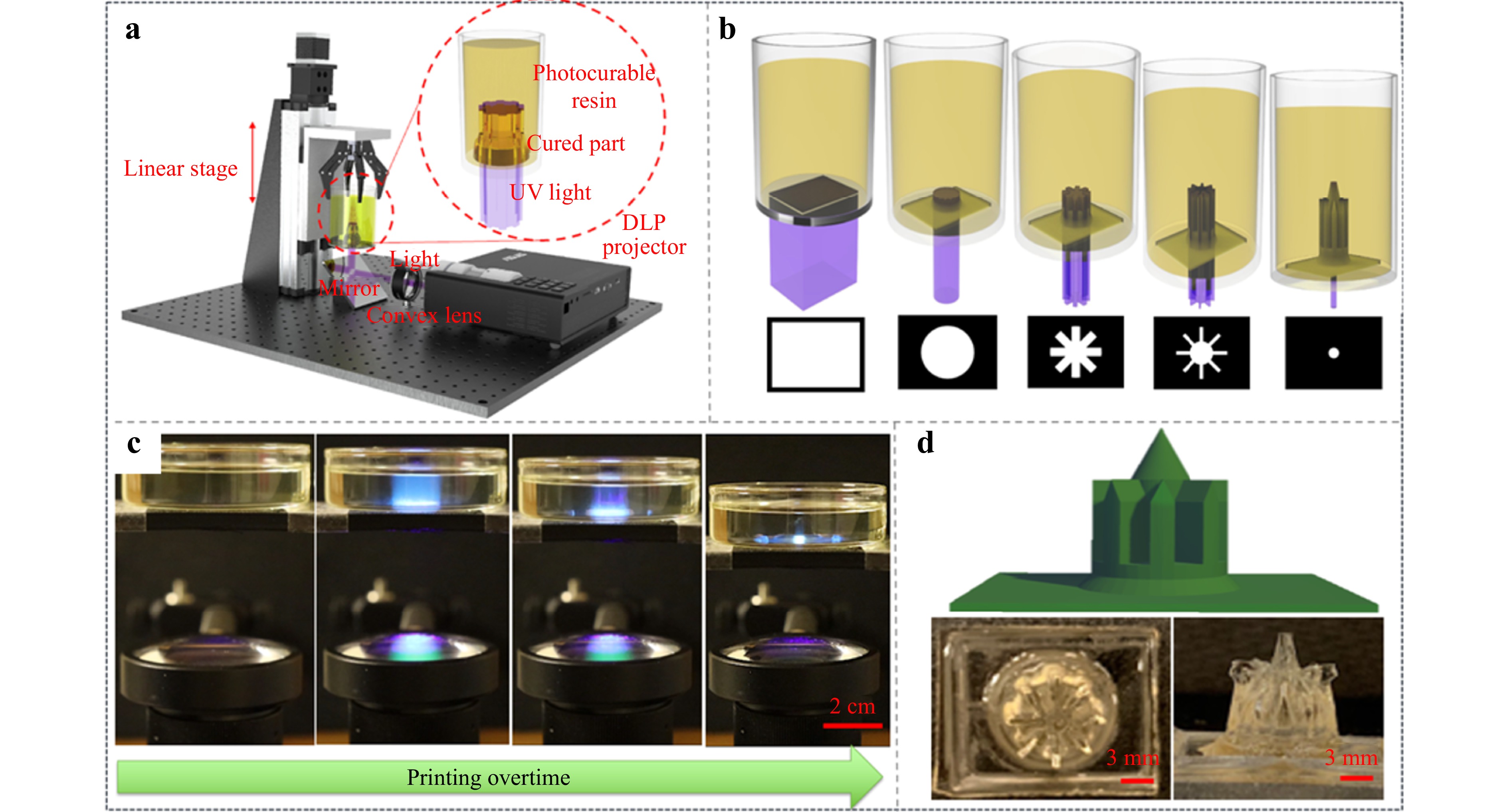
Fig. 1 Schematic illustrations of a LIDG prototype setup, b the printing process of the 3D object via the continuous projection light using a series of mask images, c physical record of the building process of LIDG with continuous projection and d printing of complex structure.
Multiple demonstration components were produced to illustrate the capabilities of this printing technique. For example, a mesoscale tower with 25 mm height was printed using LIDG process (Fig. 1c, d and supporting information video S2). To evaluate the printing speed, a cylinder measuring 20 mm in length and 10 mm in diameter was produced via LIDG in 15 seconds, whereas a cylinder with a length of 10 mm and a diameter of 500 μm took 60 seconds to complete. The difference in printing speeds between macro and micro features results from the considerably reduced light energy concentration at the micro scale, which causes slower polymerization. In the LIDG process, the movement speed of the resin container is coordinated with the growth speed of the part to ensure optimal light projection-initiated polymerization occurs at the curing site (Fig. 1c). The projected light maintains focus on the active curing region during the entire printing process, which is essential. Experimental results indicate that the maximum fabrication speed attained is 2 mm s−1, representing a speed increase of 7.2 times compared to the CLIP method20,21. The LIDG process effectively fabricates parts with large cross-sectional areas at high speeds, addressing a significant limitation of CLIP, where larger areas impede the process due to extended resin refilling times36.
-
Despite the advantage of speed, the printing accuracy of the LIDG process necessitates further optimization. Effects of distortion, attenuation, and energy accumulation were noted as light traversed the solidified region, leading to discrepancies in the intended print geometry. An analytical model was developed to examine the distribution of light energy in both solid and liquid photopolymers. This model integrates material properties, including refractive index and effective absorbance coefficient, alongside light characteristics such as half-divergence angle and beam waist diameter. Furthermore, an optimized set of projected images was generated by reducing the discrepancy between the desired and calculated energy distributions for curing specific geometries. The images were compiled into a video sequence utilized for the continuous printing of complex structures, exemplified by a cathedral tower (Fig. 1d).
To evaluate the printing resolution, a series of squares were printed and analyzed. Nine sets of squares, with length ranging from 20 mm to 300 µm, were designed and fabricated to figure our resolution limits of the system. The physical printing resolution of the proposed LIDG is 20 μm pixel−1, which is determined by the resolution of projector37. It was observed that all printed squares exhibited rounded corners instead of sharp edges (supporting information Fig. S1). This rounding effect is a result of pixel blending during projection38. Neighboring pixels contribute to higher energy levels in the center regions of the square, while corners, lacking adjacent pixels, receive less energy and thus do not fully polymerize to the same extent. According to the previous works, the energy distribution of a pixel adheres to a Gaussian function (Eq. 3):
$$ f\left(x,y\right)=A\times {e}^{-\big[\frac{{\left(x-{x}_{0}\right)}^{2}}{2{\sigma }_{x}^{2}}+\frac{{\left(y-{y}_{0}\right)}^{2}}{2{\sigma }_{y}^{2}}\big]} $$ (3) The parameters x0 and y0 denote the position of the projection beam on the coordinate plane. The variable A denotes the peak value of the light intensity, whereas x and y represent the distribution of light across the horizontal and vertical axes, respectively. An experiment was conducted to gain deeper insight into the light energy distribution along the printing direction, specifically regarding the manipulation of optical field energy distribution in liquid resin. Grayscale images were captured and processed using MATLAB, enabling the generation of matrices that represent light intensity distribution in the XY plane for each grayscale level. Subsequently, we fitted these matrices to a standard Gaussian function, constructing analytical light distribution models for different grayscale. The findings demonstrated that maximum intensity A decreases with a reduction in grayscale value, exhibiting a nonlinear relationship. It was observed that a decrease in grayscale corresponds with an increase in light dispersion along both the x and y axes, as illustrated in Fig. 2a39. Ideally, the energy distribution of a pixel should be uniform inside the pixel and no energy exists outside the pixel area which makes the distribution model a square function40. However, energy distribution of each pixel fits gaussian functions in the LIDG and the light beam of a pixel spreads to its neighboring pixels. Therefore, the light intensity at any point inside the projection image is the sum of all light intensity from neighboring pixels, which is called ‘pixel blending’ (refer to Fig. 2b). Hence, during a curing process the energy distribution is accumulated over time, which can be acquired by the following Eq. 4.
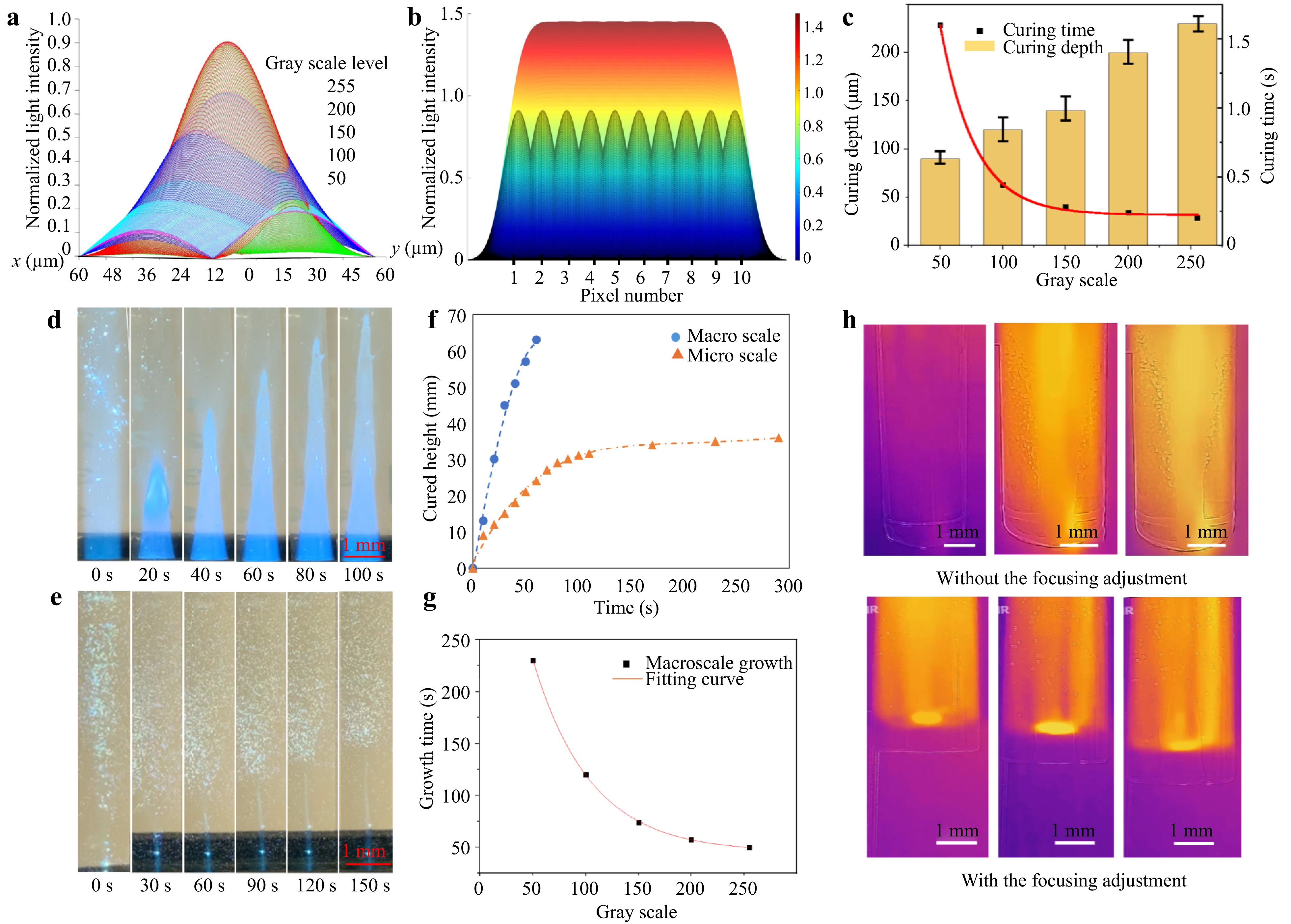
Fig. 2 a Gaussian function models of light intensity distribution of single pixel of different gray scale levels, b pixel blending effect, c curing characteristics in accordance with different gray scale levels, d macro-scale cylinder printing and e micro-scale cylinder printing via LIDG without focusing adjustment, f cured height at different time under macro and micro-scale projection without focusing adjustment, g the relationship between the grayscale levels and growth time, and h IR images of the printing tank with and without adaptive focusing adjustment.
$$ E\left(x,y\right)=I(x,y)\times \Delta t $$ (4) Where Δt is consistent with each pixel in the projection light. When the accumulated energy rises above the curing threshold δ, resin will transfer from liquid to solid state. The thickness of the cured cross-section is determined by the light penetration depth and light exposure energy. The relationship function is defined by Jacob’s equation (Eq. 5):
$$ {C}_{d}={D}_{p}ln\left(\frac{{E}_{max}}{{E}_{c}}\right) $$ (5) Where $ {C}_{d} $ is curing depth, $ {D}_{p} $ is light penetration depth, $ {E}_{max} $ is energy input and $ {E}_{c} $ is critical energy density. Light penetration depth $ {D}_{p} $ is related to the light intensity and resin transparency but critical energy density $ {E}_{c} $, also referred to as minimum energy for resin to be solidified, is determined by material itself. As shown in Fig. 2c, by incorporating the simulated light intensity results of different gray scales, the accumulated energy input $ {E}_{max} $ of the light projected by using the mask image with different grayscale can be identical. The curing time is influenced by light intensity, as increased light intensity ensures a larger rapid photopolymerization reaction rate. Consequently, an increase in grayscale level results in a reduction in curing time. However, the reaction rate of photopolymerization is constrained by the concentration of photo initiators, resulting in diminished changes in curing time when the grayscale level exceeds 150.
In the no-focus adjustment method, energy initially accumulates at the bottom of the resin vat and gradually transfers upward as printing progresses. The printing speeds of both macro- and microscale cylinders were studied (Fig. 2d, e, and the supplementary video SV2). Specifically, a 10 mm diameter circular light pattern was projected and focused on the bottom of the resin vat. Due to the translucent nature of the photopolymer, light penetrates through the entire resin, although its intensity diminishes along the optical path. At the start of the printing process, photopolymerization occurs rapidly, resulting in a solidified structure matching the projected circle’s diameter. As the cylinder grows, the polymerization rate slows, and the fabricated structure’s diameter decreases (Fig. 2f). This decline is attributed to two key factors. First, optical energy diverges from the beam waist, reducing energy distribution to voxels further from the vat bottom. Second, the solidified structure absorbs light energy, further diminishing light penetration to subsequent printing. Prolonged exposure also leads to horizontal growth due to scattered light initiating polymerization along the structure’s sides and bottom surface. Experiments using projected light patterns with varying grayscale levels revealed an exponential increase in printing time as light intensity decreased, demonstrating the nonlinear relationship between energy input and growth speed (Fig. 2g). Microscale cylinders require longer exposure times and have reduced penetration depths. A 50 μm diameter cylinder, for example, reached only one-third the height of a macroscale cylinder within 30 seconds of printing (Fig. 2e). Growth was found to halt at 34 mm due to insufficient optical energy. As the cylinder grows, light attenuation and unconcentrated energy distribution prevent sufficient free radical generation to overcome consumption rates. Consequently, photopolymerization ceases beyond this height (Fig. 2f). The increased light power or more efficient focusing could significantly improve microscale cylinder fabrication heights. To evaluate the LIDG printing process, a thermal camera was used to monitor the printing area. The thermal imaging results for printing with and without focus adjustment are shown in Fig. 2h. The heat is concentrated at the light’s focal plane and gradually dissipates over time.
-
To achieve more accurate and controllable fabrication, the energy model of LIDG with focus adjustment was investigated. The refractive indexes of the liquid and solidified resin were measured as 1.055 and 1.193, respectively. The refractive index at the solid-liquid interface was calculated to be 0.8843, providing critical insights for precise modeling of light transmission during the printing process. In the LIDG process, light penetrated the precured section before reaching the curing region. During this penetration, optical energy is attenuated, making it essential to evaluate the attenuation properties of the solidified polymer. Additionally, since optical energy also passes through the liquid resin, its attenuation characteristics must be accounted for, as photopolymerization occurs only when the accumulated energy exceeds the threshold. Using the Beer-Lambert Law, the attenuation coefficients μ for the solidified polymer and liquid resin were calculated as μL = 0.1489 W mm−1 and μs = 0.0396 W mm−1, respectively. Based on that, the attenuation and accumulation effects of optical energy within the solidified and liquid regions can be accurately modeled, enabling a comprehensive understanding and precise control of the LIDG process.
In the LIDG process, the digital model of the print is sliced into discrete cross-sections. The optical energy in the resin tank accumulates with each successive light projection, which is crucial for determining the curing duration for each cross-section. The growth rate of each cross-section is influenced by the attenuation effect, described by Eq. 6:
$$ \frac{{v}_{n+1}}{{v}_{n}}=exp(-{\mu }_{s}\cdot \Delta T) $$ (6) Where vn represents the growth rate of the nth cross-section and ΔT denotes the cross-section thickness. This energy model enables precise predictions of the growth rate and energy requirements for curing each cross-section, allowing for enhanced control of the LIDG process and improving fabrication quality and efficiency. Achieving intricate geometries with high resolution via LIDG requires a deep understanding of light transmission through both cured and uncured resin. A mathematical framework based on Walter Koechner’s model was developed to model the distribution of optical energy within the resin as shown in Eq. 741. This model is used to create a relatively light intensity field that emphasizes uniform energy distribution in targeted curative regions while reducing energy in non-targeted parts.
$$ {I}_{P}\left(x,y,z\right)=\frac{{C}_{0}}{{\pi \omega }_{P}^{2}\left(z\right)}exp\left[\frac{{-2\left(\sqrt{{x}^{2}+{y}^{2}}\right)}^{N}}{{\omega }_{P}^{2}\left(z\right)}-{\alpha }_{eff}z\right] $$ (7) Where ωP(Z) indicates the diameter of the projected light spot at position z, αeff is the effective absorption coefficient of the resin to the projection light and it can be calculated by $ {\alpha }_{eff}=\dfrac{2.303\times \left(\dfrac{{I}_{0}}{I}\right)}{layer\;thickness} $, N indicates the order of the light (N=2 for gaussian beam), C0 is a constant and can be calculated by the following equation:
$$ {C}_{0}=\frac{{P}_{0}}{\underset{Z=0}{\iint }\dfrac{1}{{\pi \omega }_{P}^{2}\left(z\right)}\mathit{exp}\left[\dfrac{{-2\left(\sqrt{{x}^{2}+{y}^{2}}\right)}^{N}}{{\omega }_{P}^{2}\left(z\right)}-{\alpha }_{eff}z\right]dxdy} $$ (8) where $ {P}_{0} $ is the light power and the expression of $ {\omega }_{P}\left(z\right) $ shows below,
$$ {\omega }_{P}\left(z\right)={\omega }_{Po}\sqrt{1+{\left[\frac{{\theta }_{P}\left(z-{z}_{0}\right)n}{{\omega }_{P0}}\right]}^{2}} $$ (9) where $ {\theta }_{P} $ is divergence half-angle of the projection light, $ {z}_{0} $ is the focusing position, $ {\omega }_{P0} $ is the radius of focused light beam and n is refractive index. To adapt the effective absorption coefficient model from laser-based systems to our projection-based light energy system, we incorporated modifications accounting for beam divergence, spectral absorption variations, and material-specific calibration. Unlike laser systems, which use collimated monochromatic light, our projection-based system involves a broader wavelength range and divergent paths, necessitating adjustments in absorption modeling.
The UV-Vis spectrometer was employed to assess the resin’s transparency at various wavelengths. Assuming each pixel functions as a Gaussian light, the light intensity distribution of the projection light inside the resin tank was simulated for both macro- and micro-scale fabrications in three-dimensional space (Fig. 3a, b). Simulations indicated that for larger exposure regions (200 pixels or more), the maximum light intensity remained stable, while for smaller areas (fewer than 50 pixels), pixel mixing resulted in considerable intensity fluctuations. The simulation corroborated experimental finding, affirming the proposed mathematical model. The light transmission patterns varied markedly between air and resin due to the effective absorption coefficient, with resin absorbing considerable light energy during photopolymerization. The LIDG approach facilitates production at both micro and macro scales by regulating energy accumulation during the continuous printing process.
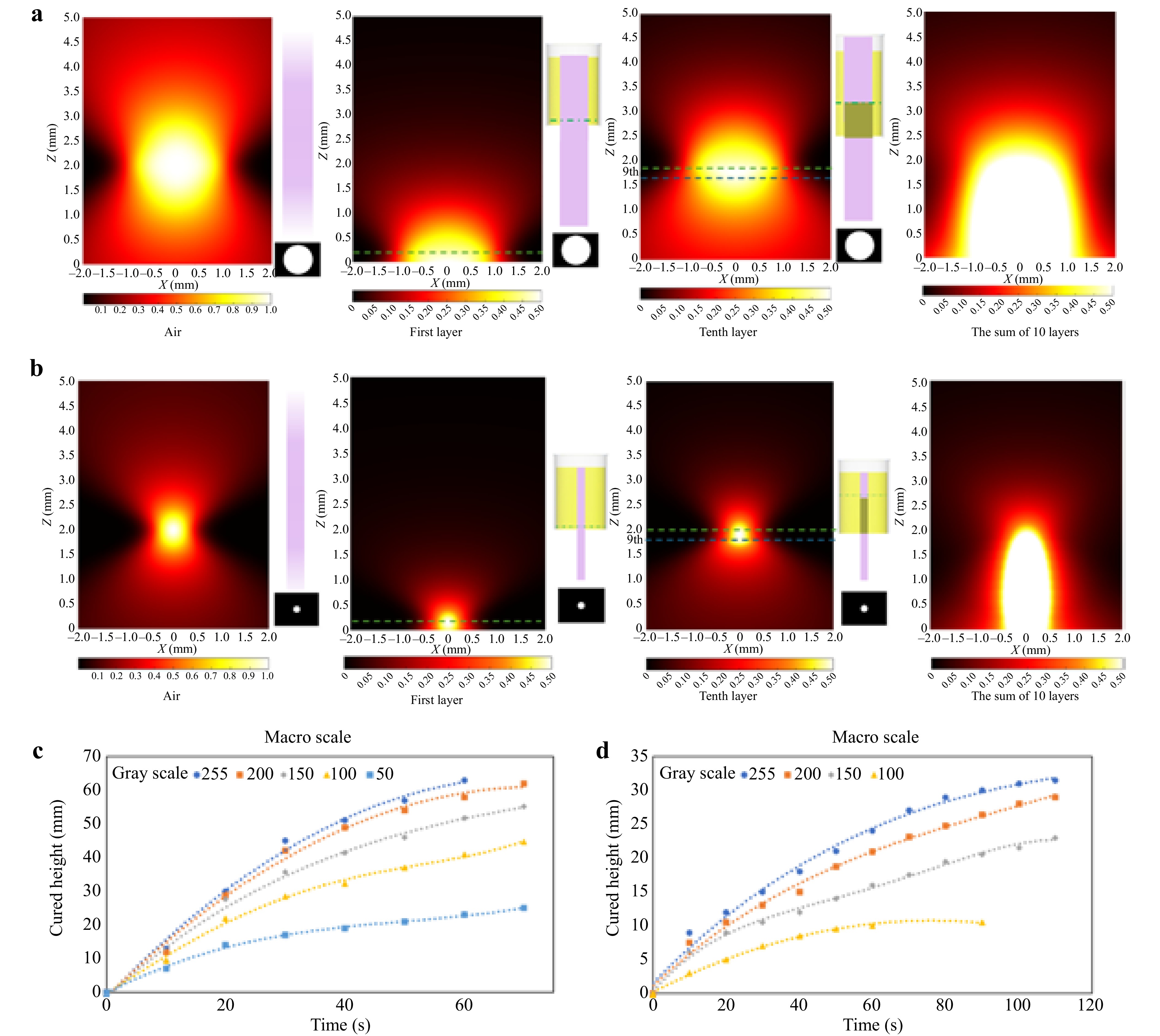
Fig. 3 Simulation of optical energy distribution inside the resin tank: a macroscale fabrication; b microscale fabrication. Relationship between curing height and time for c macro-structures at different gray scales; d micro-structures at different gray scales.
In micro-scale LIDG printing, energy dispersion from the projection light amalgamates over adjacent pixels, resulting in a threshold of 50 pixels. Beyond this point, the energy level remains steady, and the cure duration remains unchanged. Curing time for projections under 50 pixels fluctuates based on pixel count due to variations in energy accumulation. The pixel-dependent energy distribution necessitates an understanding of the specialized curing characteristics for micro-scale projections to attain precise micro-scale production. The growth rate for micro-scale printing was examined by projecting the same micro-scale mask image onto a resin-filled tank. Decreased grayscale levels led to reduced curing speeds, and when grayscale levels dropped below 50, photocuring ceased due to inadequate light intensity. The average printing speed decreased from 400 μm s−1 with full light projection to 167 μm s−1 when using a 100-grayscale mask image. (Fig. 3c) Additionally, a constraint on the maximum curing height was noted for micro-scale structures, attributed to the attenuation of optical radiation as it traverses previously cured areas. A mathematical correlation (Eq. 10) between grayscale level and printing speed was established, demonstrating the relationship between energy input and growth rate at various grayscale levels in the LIDG process.
$$ V=0.2529ln\left(g\right)-0.9977\;\;for\;\;g\ge 100 $$ (10) To further improve the printing quality of micro-scale fabrication, reducing light penetration depth was critical. This was accomplished by incorporating non-reactive dye (Oil Red O) into the resin, thereby diminishing light penetration through an increase in the resin’s absorption coefficient. Increasing the Oil Red concentration decreases the characteristic penetration depth $ {h}_{a} $ and the functional relationship between characteristic penetration depth $ {h}_{a} $ and dye concentration C is given by $ {h}_{a}=1/\left(\epsilon C\right) $, where ɛ is absorptivity related index. We conducted a series of experiments to explore the curing characteristics of resin with different dye concentrations and then fit the model with the experiment results. Experiments revealed that adding dye significantly reduced the growth rate and maximum curing height (Supporting Information, Fig. S3a, S3b). At dye concentrations exceeding 0.025%, the process halted after 120 seconds because the light energy reaching the precured region was insufficient to meet the threshold required for photopolymerization. The mathematical model was validated through linear correlations between penetration depth and exposure time, establishing a predictable relationship between dye concentration C and penetration depth $ {h}_{a} $ (Supporting Information, Fig. S3c). Additionally, the impact of grayscale levels on maximum cured height in microscale printing was examined (Fig. S3d). With the addition of 0.4% dye, the maximum curing height dropped from 6 mm to 150 μm.
-
For macro-scale LIDG fabrication, the control of polymer growth under the light exposure will be crucial because the curing speed will be in mm s−1 scale for macro scale structures which means the loss of focus is more severe if growth speed does not match the move speed of resin vat. Different gray scale levels of macro scale circles were projected with focus adjustments and the whole growth processes were recorded using CDC camera. As shown in Fig. 3c, depicting macro-scale cure, elevated grayscale levels (e.g., 255 and 200) lead to accelerated growth rates and increased structure height within a reduced timeframe. Higher grayscale values correlate with increased light intensity, expediting the curing process and enabling the structure to attain greater heights more rapidly. The growth curves demonstrate that, although beginning development is swift, the pace diminishes with time as the structure ascends, corresponding with the reduction of light through hardened resin parts. This slowing is anticipated owing to the heightened absorption and dispersion of light in denser resin segments. Specifically, the beginning printing speed of cylinder with 10 mm diameter was 1.3 mm s−1 and it turned to be smaller which is 600 μm s−1 after 1 min’s print using full scale light projection. For micro-scale growth rates are often slower, exhibiting diminished heights relative to the macro-scale graph (Fig. 3d). The reduced growth rate is attributable to the diminished energy penetration necessary for precision in micro-scale structures. Increased grayscale levels promote accelerated growth; yet, the rate is regulated to avert over-curing, which is essential for attaining micro-level details. At lower grayscale levels (e.g., 100 and 150), the cured height attains a plateau more rapidly, signifying restricted energy penetration and highlighting the necessity for meticulous intensity modifications to reconcile speed and resolution at micro sizes.
In macroscale printing, both light exposure and photopolymerization generate heat, leading to localized temperature variations and differences in liquid density. These density variations are particularly pronounced in low-viscosity materials, causing the curing gel to move along with part growth, which can result in defects on the top surface of the prints (see Supporting Information Fig. S4a). To investigate the influence of exposure on liquid flow within the resin tank across different viscosities, a series of photopolymer resins with varying weight ratios of BPAGDA and PEGDA were tested to achieve accurate printing (see Supporting Information Fig. S4b). The rheological behaviors of these resins were also studied (see Supporting Information Fig. S4c). Various structures were printed using BPAGDA/PEGDA resins to determine the critical viscosity thresholds necessary for printing macroscale parts without gel movement (see Supporting Information Fig. S4b, S4d). The critical viscosity was found to be 5 Pa·s, at which macroscale structures could be successfully printed under static conditions. The corresponding optimal weight ratio of BPAGDA to PEGDA was determined to be 1.75.
To evaluate the printing capability, the LIDG process was employed to fabricate micro- and macro-scale structures. Various structures, such as a microlens array, bioinspired hydrophobic structures, and macroscale ASU logos and QR code, were printed. Specifically, the lens array, produced from transparent resin within 3-second (supporting information, video SV4), demonstrated high fidelity, and each individual lens conforms precisely to the design specifications (Fig. 4a). Where, Fig. 4b illustrates macro-scale fabrications employing the LIDG technique, with an ASU logo and a QR code. The ASU logo was printed with resin at a dye concentration of 0.01 wt.% for precise curing, whilst the QR code, featuring both macro and micro-scale elements, was printed at a higher dye concentration of 0.025 wt.% to attain intricate patterns. The manufacture of QR code exemplifies the process’s capacity to manage multi-scale components inside a singular structure, which is beneficial for applications necessitating embedded micro-details in bigger products. These results demonstrate LIDG’s capacity to generate high-resolution structures with complex designs, integrating both large and small components. Furthermore, two biomimetic interfacial structures were fabricated via LIDG, drawing inspiration from naturally occurring hydrophobic structures, including the hierarchical structures observed in springtails and the triangular arrays present in daisies. The micro-scale structures exhibited significant hydrophobic properties in contrast to flat surface, which is hydrophilic. A water droplet on the LIDG printed bioinspired triangle array surface exhibited a larger contact angle of 135 degrees, signifying improved hydrophobicity (Fig. 4c, d). This demonstrates that LIDG is capable of effectively replicating functional biomimetic hierarchical structures with features ranging from microscale to macroscale. By modifying resin curing characteristics, such as pigment concentration, the LIDG technique attains precise control over curing height, speed, and detail resolution, facilitating multi-scale production within a singular workflow. These findings validate the LIDG process as a flexible and expeditious fabrication technique appropriate for use in optics, biomimetic engineering, and functional interfacial surfaces.
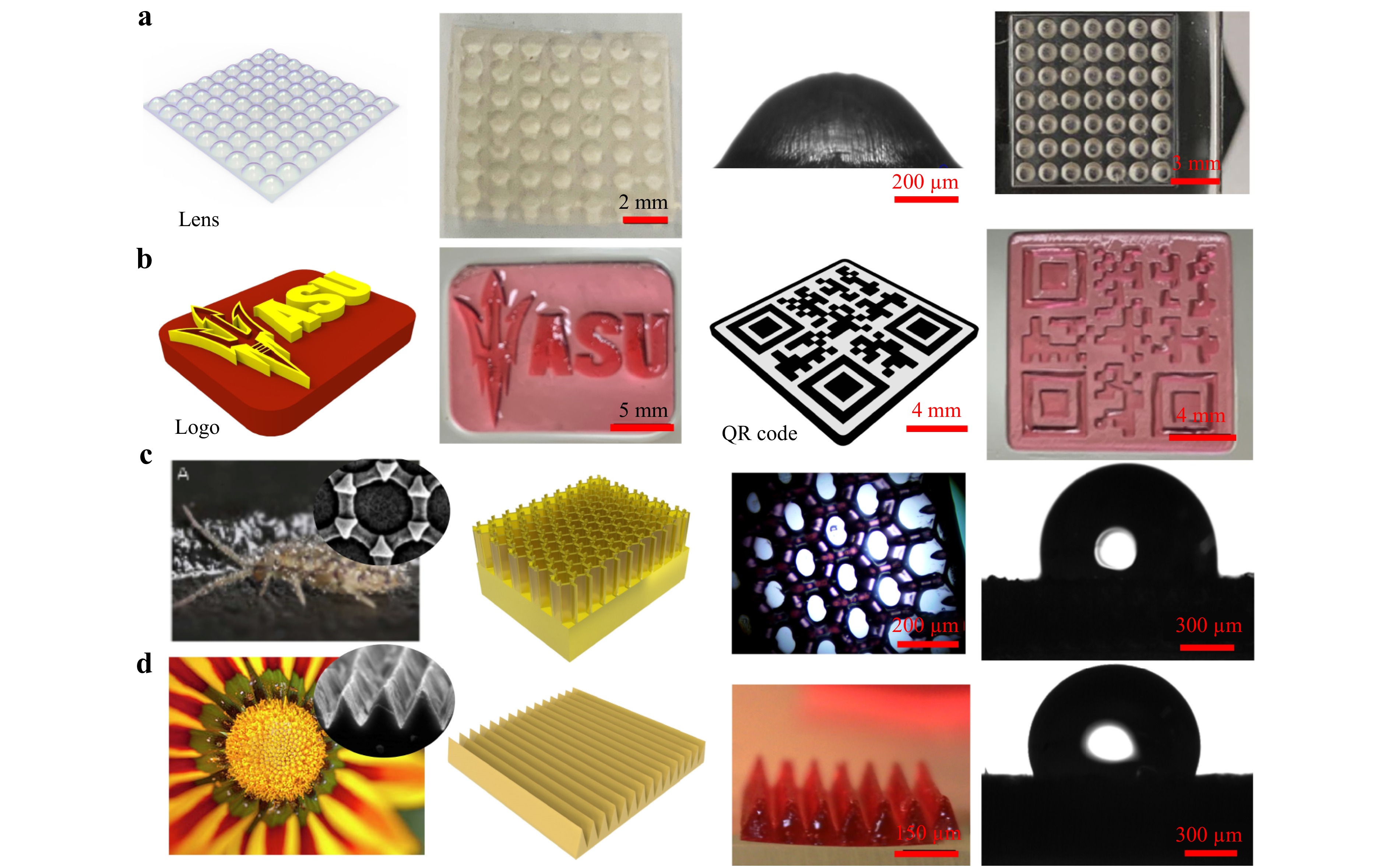
Fig. 4 Macro and Micro-scale fabrication results a Designed CAD model, printing results and side view microscope image and demo test of transparent lens array; b CAD model and fabrication results of ASU logo and QR code; c Hierarchical surface structure of springtails (Collembola), CAD model of biomimetic structure, microscope image of fabrication results and contact angle test results; and d Triangle array surface structure of daisy, CAD model of biomimetic structure, microscope image of fabrication results and contact angle test results.
-
Ultimately, a critical insight regarding the printing speed, energy distribution, and resolution of the LIDG process are also examined and demonstrate its performance across various light intensity and dye concentrations, alongside its competitive position relative to other AM techniques. The experiments were conducted to figure out the relationship between light intensity and average printing speed. As the light intensity rises, indicating a greater optical energy output, the average printing speed markedly increases (Fig. 5a). This is attributable to the fact that elevated the strong light intensity expediting the rate of photopolymerization and hence improving the curing speed. Notably, when the mask image grayscale values exceed 150, the curing speed acceleration begins to decline, suggesting a saturation threshold where additional energy input yields diminishing returns. This tendency corresponds with the constraints of PI concentration, as excessively high intensities may not further augment the healing rate. Conversely, Fig. 5b illustrates the inverse relationship between dye concentration and printing speed, highlighting the trade-offs inherent in optimizing the micro-precision process. As the dye content in the resin escalates, the average printing speed diminishes significantly. The dye absorbs more light, diminishing the energy available to penetrate resin at higher position and commence curing. Increased dye concentrations lead to diminished cure height and lowered growth rate, which can be beneficial for attaining fine control along the z-axis, especially in micro-scale fabrications. In applications necessitating complex micro-scale details, the introduction of a regulated quantity of dye facilitates the preservation of high resolution in the z-direction, albeit at the expense of overall growth rate. However, increasing dye concentration beyond approximately 0.025 wt.% substantially reduces printing speeds, making it impractical for high-speed applications. Consequently, it is imperative to equilibrate dye concentration and grayscale level to enhance both velocity and precision.
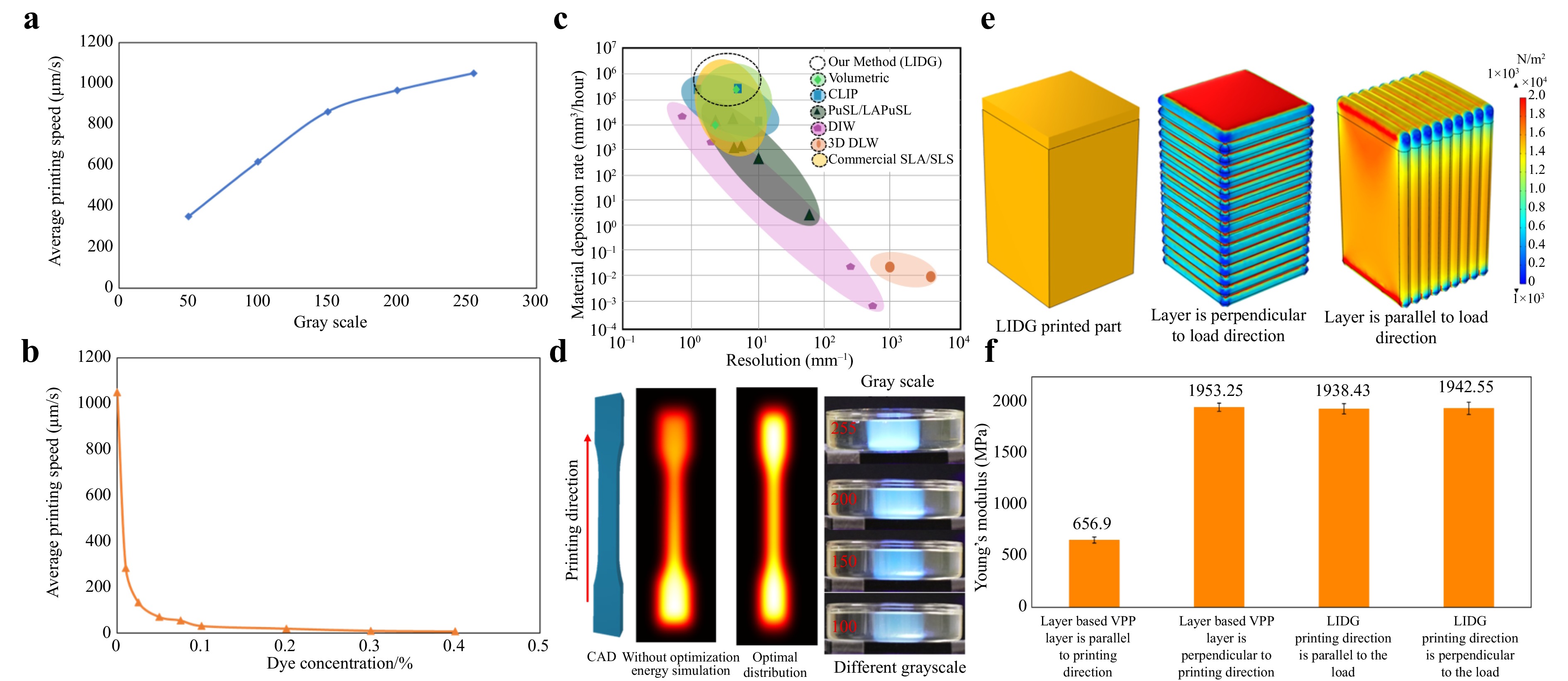
Fig. 5 Effects of a light intensity on the printing speed and b dye concentration; c compassion on resolution on printing speed and material deposition rate; d Illustration of optimal energy distribution and the printing images under different light intensity; e FEA simulation and f the young’s modulus of the tensile test of the samples printed via layer based VPP and LIDG.
The material deposition rate and resolution of the proposed LIDG process were compared with several AM techniques, including volumetric printing4, PμSL/LAPμSL42–45, CLIP21, DIW46–48, and commercial SLA/SLS49. The LIDG process achieves a high material deposition rate while maintaining fine resolution, offering a significant advantage over traditional AM methods such as commercial VPP and DIW, which often require a trade-off between resolution and speed. The LIDG technique attains manufacturing speeds comparable to other volumetric printing approaches, with a resolution suitable for both macro-scale and micro-scale applications (Fig. 5c). LIDG demonstrates its versatility as an AM technology by delivering both high speed and high resolution, accommodating diverse fabrication needs ranging from intricate microstructures to larger substrates. Additionally, experiments were conducted to examine the relationship between grayscale levels and the mechanical properties of LIDG-printed samples (Fig. 5d). The optical energy distribution was optimized to ensure uniform crosslinking rates, preventing anisotropic mechanical performance in the printed parts. Tensile test results showed a positive correlation between light intensity and key mechanical properties, such as Young’s modulus and maximum stress (see supporting information, Fig. S5). This tunability allows for the fabrication of structural components with tailored mechanical characteristics. Furthermore, the LIDG process volumetrically prints parts, ensuring homogeneous energy distribution compared to conventional layer-based VPP processes. This capability eliminates issues associated with uneven energy exposure, resulting in homogeneous mechanical performance and consistent quality across the entire printed structure (Figs. 5e, f, and supporting information, Fig. S6).
-
The Light-Initiated Direct Growth (LIDG) process represents a new linear volumetric printing strategy, addressing the limitations of traditional layer-based AM by enabling continuous, rapid production of intricate, multi-scale structures. By controlling optical energy distribution, LIDG initiates photopolymerization along Z direction within a liquid resin vat, drawing inspiration from natural growth processes. Eliminating the need for layer-by-layer construction, LIDG overcomes challenges such as layer separation and resin refilling, allowing for the seamless curing of complex geometries. This study optimized the LIDG process for both micro- and macro-scale fabrication. Experiments in micro-scale printing revealed that the light intensity directly impact curing speed, with lower levels reducing growth rates. The addition of non-reactive dyes, such as Oil Red O, effectively reduced the maximum printing height, enhancing resolution and precision. For macro-scale printing, challenges like optical energy attenuation and resin movement during exposure were addressed through resin viscosity optimization, minimizing undesired features and improving accuracy and stability. The LIDG process was further refined using mathematical modeling and experimental validation, achieving high-speed printing without compromising resolution across scales. Demonstrations of biomimetic surfaces and complex macro-scale models, including ASU logo and QR codes, showcased the versatility and potential of LIDG for producing precise, functional components with customizable material properties. The mechanical properties of LIDG-printed samples, including Young’s modulus and maximum stress, were shown to correlate positively with light intensity, enabling precise tailoring of material performance for specific applications. The LIDG process ensures isotropic mechanical performance by volumetrically curing the resin, avoiding the anisotropic properties typically associated with layer-based AM methods.
Despite these advances, challenges remain in balancing printing speed and fidelity across different scales. Techniques such as graded exposure and dynamic grayscale adjustment can be employed to more precisely modulate optical energy input, mitigating undercuring in microscale regions and overcuring in larger features. Additionally, the current maximum achievable height of 34 mm is constrained by optical attenuation through cured resin; this may be addressed by integrating optical system enhancements and dynamic focal plane modulation to maintain energy delivery efficiency. Looking ahead, future research will focus on expanding the accuracy and adaptability of the optical energy distribution model. While the current model has been developed through experimental testing, its ability to capture complex optical phenomena—such as scattering and refractive index changes at non-planar interfaces during photopolymerization—remains limited. To address this, we will work on developing 3D simulation frameworks combined with machine learning-assisted mask image and exposure optimization strategies for volumetric printing planning. These tools will enable optimal adjustment of local light intensity and grayscale levels to enhance resolution, printing stability, and reproducibility, particularly in macroscale fabrication. Furthermore, refinements to resin formulation—including improved dye systems and photoinitiator chemistry—will be pursued to better control light absorption and polymerization kinetics across scales. Additionally, the current disparity between microscale and macroscale fabrication speeds presents a critical challenge for volumetric printing, as it requires balancing high resolution in multiscale printing with efficient throughput. Potential strategies—such as dynamic grayscale adjustment—have been explored by others in the traditional VPP process50–53 and offer promising solutions. These techniques enable spatial modulation of optical energy distribution, enhancing microscale resolution in macroscale regions while maintaining printing efficiency at larger scales.
In summary, the LIDG process represents a significant advancement in 3D printing technology, offering a scalable and high-speed approach for fabricating multi-scale structures with minimal material constraints. Its ability to regulate optical energy and tailor material properties unlocks new possibilities for applications in sectors such as biomedical devices, optics, and mold manufacturing. Future work will focus on enhancing the optical energy distribution model based on machine learning and refining resin formulations to further expand the capabilities and applications of this innovative volumetric printing technique.
-
The authors acknowledge ASU Startup Funding, ASU NEI-STC-MADE grant, National Science Foundation (NSF grants No. CMMI-2114119, CMMI-2338752).
Linear volumetric additive manufacturing of polymer structures via light initiated direct growth
- Light: Advanced Manufacturing , (2025)
- Received: 21 December 2024
- Revised: 02 August 2025
- Accepted: 04 August 2025 Published online: 21 October 2025
doi: https://doi.org/10.37188/lam.2025.063
Abstract: Additive manufacturing (AM) encompasses a variety of techniques for creating three-dimensional (3D) structures with intricate geometries, including droplet-based and layer-based methods. Among these, vat photopolymerization (VPP), a layer-based AM technology, stands out for its ability to achieve high resolution and relatively low cost. However, traditional VPP techniques face inherent challenges such as the stair-step effect and limited fabrication speed, which constrain their application for seamless, high-throughput manufacturing. To address these limitations, continuous and volumetric photopolymerization approaches have emerged, offering enhanced precision and faster production capabilities. This study introduces a novel linear volumetric printing technique, Light-Initiated Direct Growth (LIDG), which precisely controls light energy distribution in 3D space within a liquid resin. Unlike other methods, LIDG enables curing light to penetrate pre-printed regions, achieving continuous polymerization along the Z-direction. By leveraging controlled light projection, optical energy is manipulated to initiate photopolymerization at targeted voxels, facilitating the rapid and uninterrupted construction of 3D polymer structures. A detailed optical energy distribution model is developed for LIDG, accounting for light absorption and attenuation characteristics within photopolymer resins. Additionally, the effect of resin viscosity on printing quality is systematically analyzed. Demonstrations of LIDG’s capability to fabricate large macro-scale structures with fine micro-scale features underscore its potential for advancing applications, including biomedical devices, optical systems, and soft robotics.
Research Summary
Volumetric 3D Printing: Linear growth enables high-speed, multi-scale fabrication
A new linear volumetric printing method enables ultra-fast fabrication of micro- and macro-scale 3D structures. Inspired by natural growth mechanisms, the Light-Initiated Direct Growth (LIDG) technique optimizes optical energy to drive polymerization along a linear path through transparent resin. The process bypasses conventional layering, eliminating resin refill delays and enabling volumetric production. Through modeling and experiments, the authors studied light distribution and modulation and resin polymerization to achieve high fidelity, multi-scale structures fabrication with isotropic properties. Applications include biomedical devices, optical systems, and bioinspired interfaces.
Rights and permissions
Open Access This article is licensed under a Creative Commons Attribution 4.0 International License, which permits use, sharing, adaptation, distribution and reproduction in any medium or format, as long as you give appropriate credit to the original author(s) and the source, provide a link to the Creative Commons license, and indicate if changes were made. The images or other third party material in this article are included in the article′s Creative Commons license, unless indicated otherwise in a credit line to the material. If material is not included in the article′s Creative Commons license and your intended use is not permitted by statutory regulation or exceeds the permitted use, you will need to obtain permission directly from the copyright holder. To view a copy of this license, visit http://creativecommons.org/licenses/by/4.0/.

 DownLoad: