





-
Chronic wounds represent a significant clinical challenge and are characterised by prolonged healing processes and high susceptibility to complications such as infection and bleeding1,2. Although traditional wound dressings such as gauze and hydrogels are widely used clinically, they typically exhibit poor skin penetration3,4. Additionally, these conventional dressings lack real-time feedback functionality, which makes implementing precise interventions in response to dynamic changes in the wound microenvironment difficult. Therefore, transdermal delivery and monitoring platforms must be developed. Such platforms should overcome the stratum corneum barrier, achieve controlled drug release, and enable continuous monitoring of the wound status5–8.
Microneedle technology achieves skin penetration without damaging nerves and blood vessels9,10. This enables minimally invasive drug delivery and has great potential for treating chronic wounds. The effective treatment of different wounds with microneedle patches depends on precise dimensional control to match various wound morphologies and depths11. Superficial wounds require shorter microneedles (200–400 μm), whereas deep diabetic ulcers demand longer penetration depths (600–900 μm). An insufficient penetration depth can result in therapeutic failure, whereas excessive penetration causes pain and tissue damage. Additionally, tip sharpness directly affects insertion comfort and success rate. For irregular wounds, achieving uniform drug distribution requires precisely customized microneedle geometries12. Existing microneedle manufacturing techniques, including photolithography13, 3D printing14, and etching15, each offer distinct advantages. Nevertheless, they have common challenges such as difficulty in balancing high precision with rapid customisation, high costs, limited material selection, and low geometric design freedom. These challenges hinder the simultaneous achievement of wound management with high precision, high speed, cost-effectiveness, and material compatibility.
A reliable wound treatment requires microneedle platforms with active therapeutic interventions. Among the various therapeutic modalities, electrical stimulation (ES) has emerged as a promising approach that promotes cellular migration and tissue regeneration while enabling dynamic drug delivery control through the electrochemical modulation of hydrogel permeability16. However, most ES systems rely on external power sources, which increase the device complexity and wear burden. Beyond therapy, continuous wound assessment is critical, as microenvironmental parameters such as pH and temperature reflect the healing progress and potential complications17. Convenient and continuous monitoring of these parameters is essential for effective wound care. Current wound-monitoring approaches rely on intermittent clinical assessments or complex electrochemical sensors that require external power supplies, limiting their practical application in continuous care. Therefore, integrating precision manufacturing with self-powered therapeutic intervention and monitoring into a single microneedle platform presents a challenge in wound management.
In this study, we developed a rapid and high-precision microneedle mould-fabrication method based on CO2 laser defocusing. By adjusting the defocusing conditions and laser parameters, we achieved multi-scale control of the microhole morphology through plasma-shielding effects and controlled energy density. This approach enables the fabrication of microneedle templates with tip diameters as small as 2.2 μm. A self-powered microneedle patch (SPMNP) was developed using these precisely fabricated templates. The SPMNP integrates triboelectric nanogenerator (TENG)-based ES for controlled drug release and colorimetric sensors for real-time pH and temperature monitoring. Harnessing bioelectrical signals generated from body movements modulates hydrogel permeability, enabling stimulation-responsive delivery of anti-inflammatory therapeutics directly to chronic wound sites. Simultaneously, the embedded cholesterol liquid crystal and phenol red colorimetric modules provide continuous monitoring of the wound status through colour changes. Based on the developed manufacturing technology, this multifunctional patch offers a personalised solution for chronic wound management.
-
Laser processing is a highly controllable and flexible manufacturing method18,19. The ablation effects caused by focused and divergent beams can be tuned by adjusting the focal position. In this study, a laser defocusing strategy was developed for controllable microneedle mould fabrication by utilising the synergy between the energy density gradients and plasma shielding effects. The CO2 laser system employed different defocusing conditions, directing the beam to converge at various heights relative to the material surface. Varying the focal point position controlled these synergistic effects, thereby enabling the fabrication of dimensionally tuneable inverted conical microhole templates. These templates were filled with hybrid conductive hydrogels to form upright conical microneedles. An SPMNP is fabricated using this approach (Figs. 1a and S1). The SPMNP achieves self-powered ES based on TENG principles, enabling controlled drug release without external power supplies. Integrated colorimetric sensors enable wire-free real-time wound monitoring. Customisable microneedle geometries enable personalised treatment of on-demand wound types (Fig. S2).
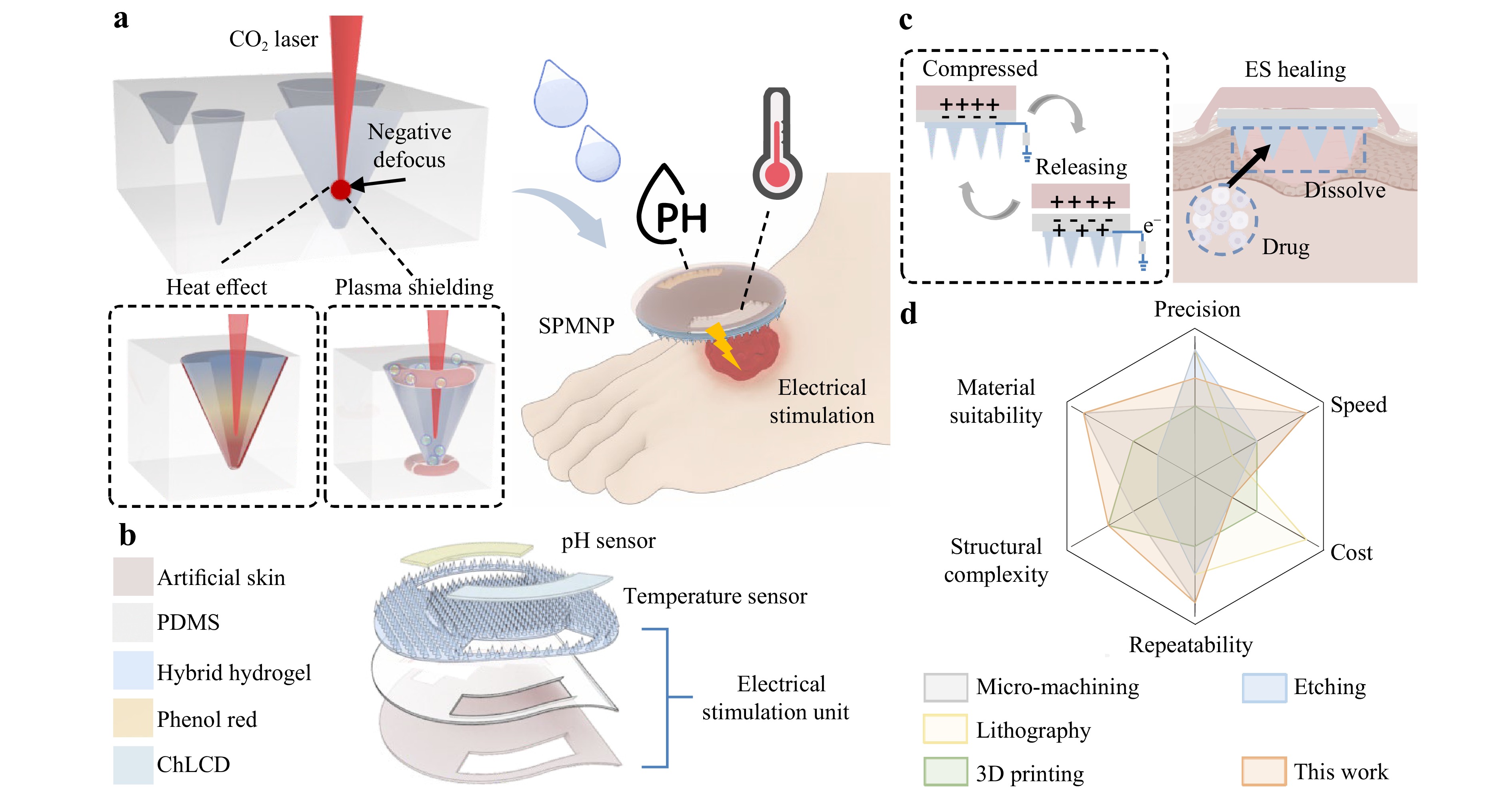
Fig. 1 Concept of laser-engraved SPMNP for drug delivery and wound monitoring. a Defocusing manufacturing strategy via CO2 laser for creating controllable microneedle moulds. The templates are filled with hybrid materials and colorimetric indicators to produce the SPMNP. b Schematic view of the SPMNP. c Triboelectric mechanism of the SPMNP for enhanced drug delivery. Body movements generate electrical output for drug release and wound healing. d Radar chart evaluating the technique of defocused laser processing with other microneedle manufacturing methods including six key parameters: precision, speed, cost, repeatability, structural complexity, and material suitability.
Fig. 1b shows the exploded structure of the SPMNP, which is primarily divided into two parts: an ES unit based on the TENG for drug release and a colorimetric sensing unit. The ES unit consists of triboelectric, dielectric, and electrode layers. Specifically, artificial skin serves as the triboelectric layer, polydimethylsiloxane (PDMS) functions as the dielectric layer, and conductive drug-loaded hybrid hydrogel microneedles act as the electrodes. The colorimetric sensing unit incorporates two sensing materials. Phenol red serves as a pH sensor, with colorimetric changes in response to variations in the wound pH, thereby indicating the infection status or healing progression. In addition, cholesterol liquid crystal (ChLCD) functions as a temperature sensor with thermochromic properties, providing temperature feedback that corresponds to wound inflammatory responses.
Based on the overall design described above, the SPMNP achieves wound treatment via a TENG-based mechanism that enables ES for controlled drug release (Fig. 1c). Specifically, spontaneous body movements, such as breathing and routine motion, induce compression and release cycles in the patch, thereby achieving charge transfer and current output. The TENG-based ES generates a current that facilitates controlled drug release from the microneedle matrix. ES promotes wound healing by enhancing cellular regeneration and tissue repair processes through bioelectrical effects. Regarding the fabrication approach, the defocused laser processing technique developed in this study was compared with other representative processes used for microneedle manufacturing (Fig. 1d). The scoring of the established methods was based on data from the corresponding literature, whereas the laser defocusing method was scored from the measurements in this study20–24. A six-indicator evaluation demonstrated well-rounded performance across all parameters, indicating that the technique is suitable for scalable microneedle manufacturing.
-
To investigate the effects of the laser parameters on the shape and dimensions of the ablated inverted conical microholes, we first analysed the laser-interaction processes. The CO2 laser beam propagates as a Gaussian beam, converging to a minimum waist radius w0 at the focal point25,26 (Fig. S3a). Because it propagates as a Gaussian beam, the laser beam spreads as it propagates away from the focus27,28. Accordingly, the intensity distribution of a Gaussian beam varies with spot size (Fig. S3b), with the peak intensity occurring at the minimum spot radius and decreasing as the spot radius increases. Owing to this variation, the focal position of the laser beam relative to the upper surface of the sample is critical during laser processing. Three focal conditions were defined: positive defocus, zero defocus (in-focus), and negative defocus29. As shown in Fig. S4, positive defocus occurs when the focal point lies above the sample, zero defocus occurs when it is positioned at the sample surface, and negative defocus occurs when it is located within the workpiece.
The three focusing conditions resulted in distinct energy distributions and ablation effects (Fig. 2). The blue dashed line represents the energy density generated by the laser at the focal point, and the yellow dashed line indicates the intrinsic ablation threshold of the material. Under positive defocus, the laser focal point (w0) is positioned above the material surface in air, where maximum energy density occurs. In this configuration, as the beam propagates and diverges from the focal point, the energy density gradually attenuates according to a Gaussian distribution. Fig. 2a shows that upon reaching the material surface, the energy density decreases from its focal point maximum owing to divergence. Consequently, the beam spot radius at the material surface (wp) is larger than the focal spot radius. As the laser beam penetrates the material, continued divergence and attenuation further reduce the energy density with increasing depth. Material removal occurs only when the local energy density exceeds the ablation threshold. As the energy continuously attenuates with depth, the beam energy eventually falls below the ablation threshold, thereby terminating the ablation process. This produces relatively shallow ablation depths compared with the other focusing conditions. At this terminal depth, where the energy density equals the ablation threshold, the beam spot radius (wp') is considerably larger than the focal point and the material surface.
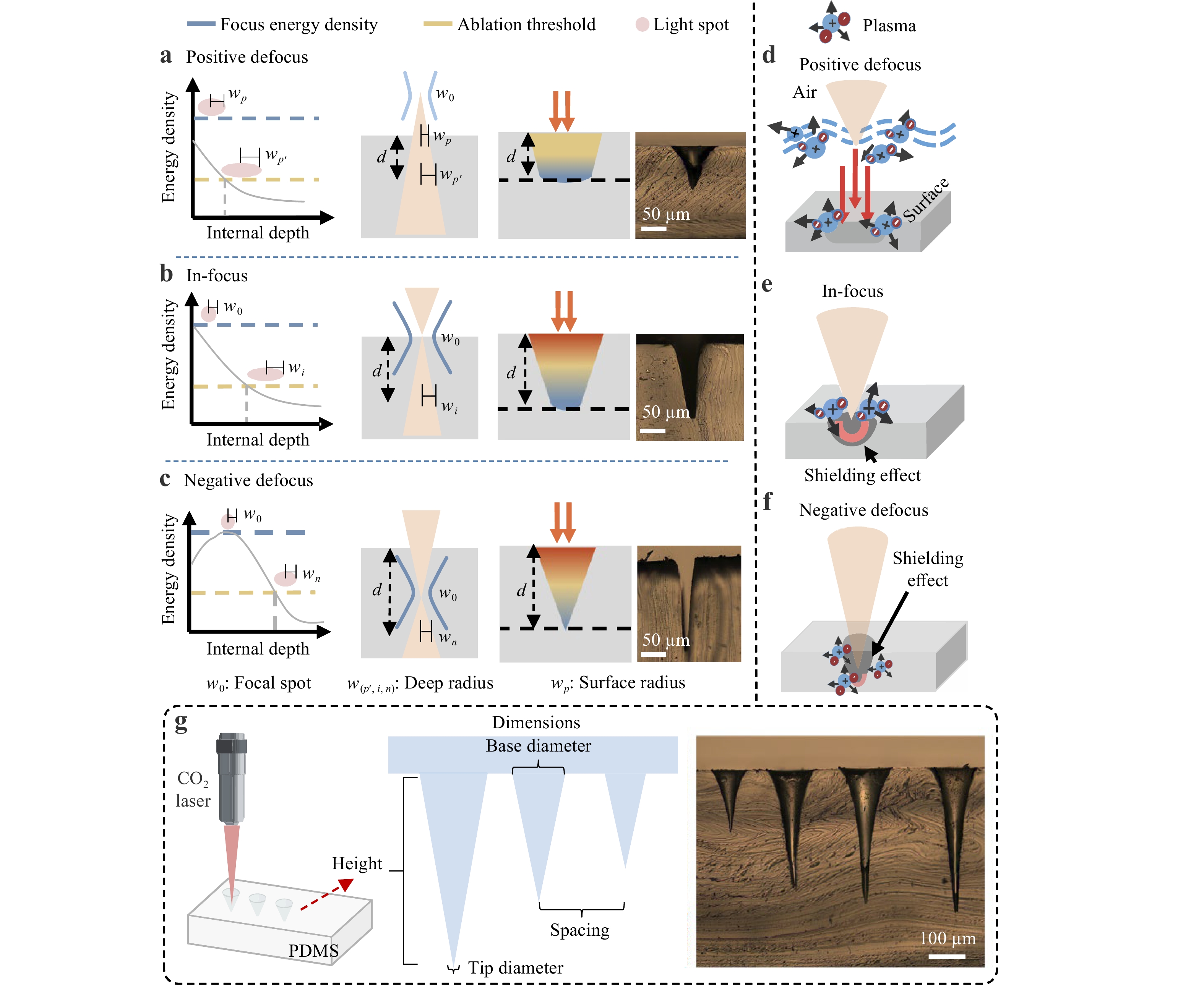
Fig. 2 Analysis of laser ablations and plasma effects under different focal distances. Energy distribution profiles and ablation characteristics under a positive defocus, b in-focus, and c negative defocus conditions. Energy density curves and ablation thresholds illustrate the relationship between focal position and material removal efficiency. Plasma effects under different focusing conditions. d Air plasma formation at positive defocus. e Confined material plasma at in-focus. f Dual plasma effects at negative defocus. g Structural parameters of CO2 laser ablation for PDMS microneedle mould fabrication. Microscopic images show controllable conical microhole structures.
Fig. 2b shows that under in-focus conditions, the maximum energy density occurs at the material surface, where the beam spot radius is the smallest. As the laser beam penetrates the material, beam divergence results in a gradual increase in the spot radius. Thus, the energy density decreases with increasing depth. As the energy density reaches its highest value at the surface, ablation is initiated most effectively at this location. The energy density remains above the ablation threshold for a greater penetration depth compared with the positive defocus condition. Ablation continues until the energy reaches the threshold level at depth d, where the beam spot radius reaches wi. This produces deeper penetration than a positive defocus, yielding a pronounced conical geometry with a narrow entrance and a relatively high aspect ratio. Microscopic imaging revealed a high-aspect-ratio conical structure with a well-defined profile.
Under negative defocus, the incident beam enters the material with a large spot radius and converges to its focal point beneath the surface (Fig. 2c). Energy density progressively increases from the surface, reaching its maximum at the focal point (w0), before decreasing at a greater depth owing to beam divergence. Consequently, the maximum energy density occurs internally rather than at the surface. This configuration enables the energy to exceed the ablation threshold (yellow dashed line) over an extended depth range, thereby enabling deep penetration of the material. The energy concentration at the buried focus enables efficient material removal at depth d, whereas the beam spot radius at this location (wn) remains relatively small, promoting precise ablation. The resulting ablation profile exhibits the deepest penetration and smallest tip among the three focusing conditions. This geometry is particularly evident in microscopic images. To complement the theoretical analysis, we used COMSOL 5.0 simulations to examine the ablation behaviour under different focal conditions (Fig. S5).
Beyond energy distribution, plasma formation is another critical factor influencing the outcomes of laser ablation. In the positive defocus mode, the focal point resides above the material surface, triggering plasma formation in the air30,31 (Fig. 2d). As the high-intensity laser beam propagates through air toward the material, it generates air plasma in the region between the focal point and the surface. This air plasma acts as an energy absorption and scattering medium, significantly modifying the characteristics of the laser beam before it reaches the surface of the material. Air plasma formation introduces a shielding effect on the ablation process. The plasma-absorbed partial laser energy reduces the effective energy density reaching the material surface. In addition, plasma-induced beam scattering and defocusing can alter the spatial energy distribution, potentially expanding the interaction zone on the material surface. Moreover, when ablation begins, the vaporised material and ablation debris interact with the air plasma, producing a complex environment that affects the ablation dynamics. This plasma shielding reduces the ablation efficiency compared to the other two focal conditions.
The in-focus condition aligns the laser focal point with the material surface, enabling the maximum energy density to be delivered directly to the target (Fig. 2e). Upon laser irradiation, intense laser–material interactions immediately generate material plasma at the surface. In contrast to positive defocus, this plasma confinement has distinct morphological advantages. Plasma confined within the microhole creates a focused channel that enhances the energy-coupling efficiency to the cavity walls. This confined plasma environment facilitates deeper energy penetration and more efficient material removal at greater depths. This maintains a higher energy density and achieves a significantly greater ablation depth than under a positive defocus. In contrast, during negative defocus laser ablation, plasma is simultaneously generated at both the subsurface focal point and the material surface30 (Fig. 2f). The plasma induced at the focal point produces partial absorption and shielding effects on the subsequent laser pulses. This shielding redistributes the laser energy axially, thereby preventing energy wastage from excessive surface ablation. This enables continuous energy transfer deeper into the material, resulting in enhanced penetration. Simultaneously, the shielding effect reduces the radial diffusion, thus concentrating the laser energy along the axial direction to form more axially confined energy deposition. As ablation progresses and the cavity narrows, a sharp apex gradually develops at the bottom of the microhole. Throughout this process, the combined effects of plasma shielding and confinement prevent energy dispersion and provide stable energy transmission for deep ablation. Consequently, the laser-ablated microholes exhibit a larger depth and sharper apex geometry. This results in superior ablation characteristics compared with other focusing configurations.
Following the theoretical analysis of laser ablation microholes, CO2 laser ablation of PDMS was used to produce inverted conical microcavities that served as microneedle moulds (Fig. 2g). Before fabrication, the critical parameters for the microneedle design were analysed, including the base diameter, tip diameter, height, and spacing. These dimensional parameters are crucial for determining the mechanical properties, penetration capability, and drug delivery efficiency of the microneedle array. The broad base provided structural stability, whereas the sharp tip ensured skin penetration. Optical images (Fig. 2g, Fig. S6) confirmed the controllable dimensions of the ablated inverted conical microholes. The adjustment of the laser parameters enabled the fabrication of microneedles with tailored geometries. This study focused on PDMS; however, the defocusing logic is generic to laser ablation. Translating this into materials with different thermal conductivities or optical absorptions, such as metals or photoresists, requires recalibration of the laser parameters to preserve the same balance between energy confinement and thermal diffusion.
-
Microneedle fabrication involved the CO2 laser ablation of PDMS to create micropore templates. Subsequent casting, heating, drying, and demoulding produced the final microneedle arrays (Fig. 3a). The focusing lens magnification critically affected the machining performance (Fig. S7). Because the depth of focus of a relatively high-magnification focusing lens (smaller focal spot) was smaller than that of a low-magnification focusing lens (larger focal spot), it was more sensitive to the defocus distance. To achieve fine control over microneedle morphology, we used both high- and low-magnification lenses for microneedle fabrication. The effect of the laser defocus distance on the sharpness of the microneedle tip was investigated using a high-magnification focusing lens (Fig. 3b). Scanning electron microscopy (SEM) images revealed the morphological variations of microneedle tips fabricated at defocus distances ranging from −0.3 to +0.1 mm. Throughout this range, the negative defocus conditions consistently produced sharper tips than the positive defocus conditions. The tip diameter varied from ~3.5 μm at a defocus of −0.3 mm to ~4.5 μm at a defocus of +0.1 mm. The sharpest microneedle tip was achieved at a defocus distance of −0.1 mm. This was almost consistent with the mechanism illustrated in Fig. 2. These results confirmed that a negative defocus produces sharper tips through an enhanced ablation efficiency. Under identical parameters, the effect of defocus distance on the microneedle tip characteristics was investigated using a low-magnification focusing lens (Fig. 3c). As the defocus distance shifted from negative to positive, both lenses exhibited similar trends, and the tip diameter increased accordingly. However, the low-magnification focusing lens produced more features than the high-magnification focusing lens. This is because low-magnification lenses display larger spot radius than high-magnification focusing lenses. Thus, combining high- and low-magnification focusing lenses enables precise control of microneedle morphology. This provided flexibility for tailoring the microneedle geometry according to specific applications. The defocus distance also affects the base diameter. Base diameter increased gradually from ~175 μm at a defocus of −0.3 mm to ~225 μm at a defocus of +0.1 mm (Fig. S8). This expansion resulted from the increased beam size distributing the laser energy over a broader area, thereby reducing the peak energy density while expanding the ablation zone.
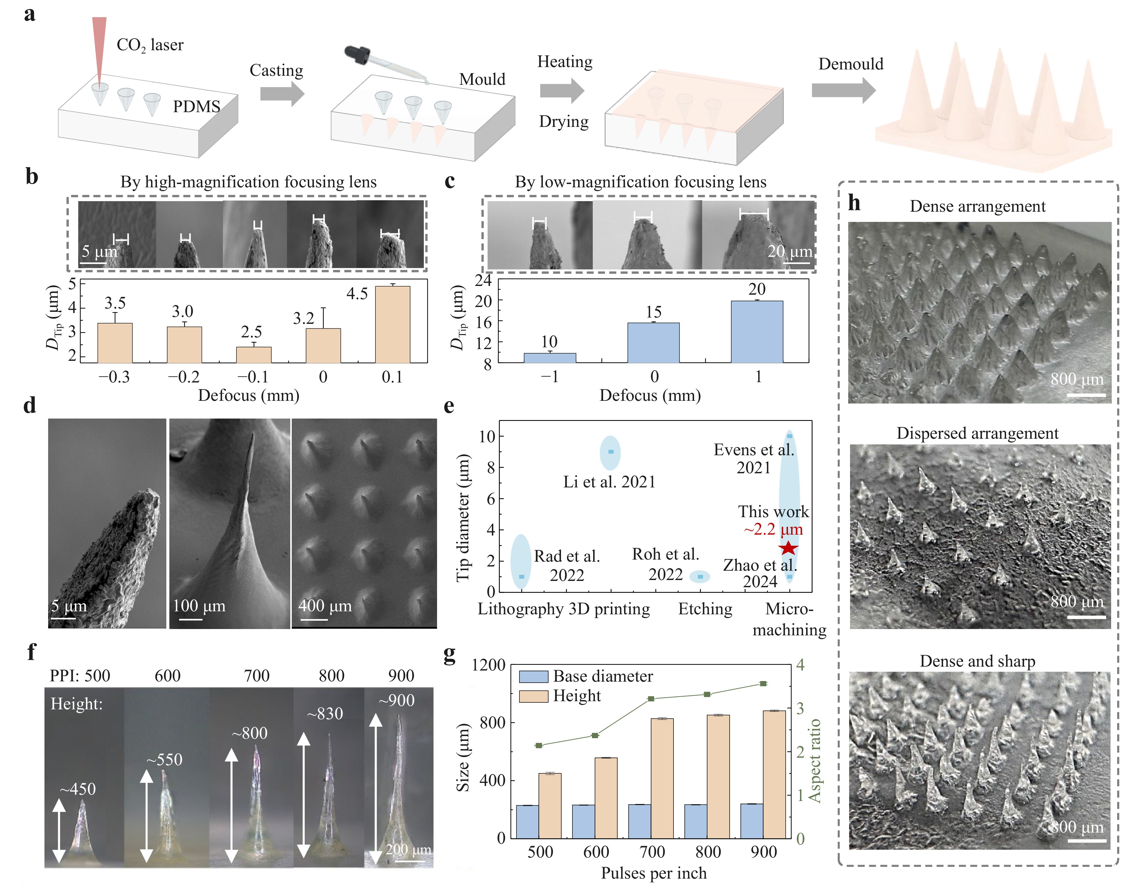
Fig. 3 Fabrication of microneedle structures by laser processing and pattern transfer. a Schematic of the MNP fabrication process. Influence of defocus distance on microneedle tip diameter using b high-magnification focusing lens and c low-magnification focusing lens (power: 24 W, PPI: 900). d SEM images of microneedle morphology at different magnifications. e Comparison of tip diameters achieved by different manufacturing techniques. This laser micromachining approach achieves ~2.2 μm-tip diameter. f, g Effect of PPI on microneedle height and aspect ratios (power: 24 W, defocus: −0.1 mm). Increasing PPI raises height while maintaining constant base diameter, demonstrating precise morphological control. h Morphologies of different microneedle arrays. Data in b, c, and g were presented as means ± SD, n = 3.
Fig. 3d shows high-resolution SEM images of the individual microneedles and microneedle arrays, demonstrating excellent uniformity and structural integrity. To assess the fabrication accuracy, we compared the tip diameters with those produced using lithography20, 3D printing21, etching23, and micromachining techniques22,24 (Fig. 3e). The results demonstrated that this study achieved a tip diameter of ~2.2 μm, which was competitive with other fabrication methods. In addition to the laser focus, the laser pulses per inch (PPI) and power influence the overall microneedle morphology. The effects of PPI on height and base diameter were first investigated. As PPI increased from 500 to 900, microneedle height increased from ~450 to ~900 μm while maintaining a constant base diameter, thereby resulting in an increased aspect ratio (Fig. 3f, g). The higher PPI delivered more energy to the material, increasing the deposited energy per unit length. The PPI modulated the axial energy accumulation, whereas the radial dimension remained fixed by the beam geometry. Consequently, more controlled material removal was achieved in the vertical direction, whereas lateral ablation remained relatively unaffected. The results validated the capability of adjusting the PPI to precisely control the microneedle morphology, enabling the optimisation of aspect ratios for various applications. A comparative analysis of the effects of the power and defocus was also conducted. Increasing the power increased the energy intensity, producing a larger ablation depth and wider base. Increasing the laser power gradually increased both the microneedle height and base diameter, with the height more than doubling from 12 to 24 W, whereas the aspect ratio increased from ~2.1 to 3.5 (Fig. S9a). However, further increasing the laser power would intensify heat accumulation and damage the cavity walls; thus, 24 W was set as the upper limit of the working window. A defocus adjustment exhibited a nonlinear effect on microneedle height, with the height peaking at −0.1 mm (Fig. S9b). Under an excessive negative defocus, the excessively deep focal point led to premature energy attenuation. Energy was dissipated through thermal diffusion and absorption by the material above the focal point, thereby reducing both energy density and ablation depth. Additionally, plasma formation further absorbed incident energy, reducing the surface energy density. An excessive positive defocus reduced the vertical energy concentration. The low-magnification focusing lenses exhibited similar trends (Fig. S10).
Mechanical testing confirmed that the microneedles possessed adequate strength for transdermal applications. Both microneedle-1 (small-tip) and microneedle-2 (large-tip) exhibited failure forces exceeding 0.4 N/needle (Fig. S11a), ensuring reliable skin penetration without causing structural damage. Clear microneedle insertion marks were observed on the skin model (Fig. S11b, c). The successful fabrication of different patch configurations by adjusting the laser parameters demonstrated the tunability, reproducibility, and precision of this method (Fig. 3h). The dense arrangements had closely packed microneedles with uniform spacing and consistent geometry. The dispersed configurations had microneedles distributed over wider intervals while maintaining structural integrity. The dense and sharp configuration combined a high needle density with optimised tip sharpness. These findings validated the flexibility of the proposed laser-defocusing processing technology for manufacturing microneedle patches. In practice, this enables the patch geometry, including needle height, tip sharpness, and overall shape, to be designed within minutes according to specific wound requirements, thus supporting customisation for different wound types and individual patients.
-
Using this fabrication approach, electrical stimulation microneedle patches (ES-MNPs) were developed and characterised for transdermal drug delivery. Conductive microneedles were fabricated by casting and demoulding a mixed ionic liquid (IL)/poly(3,4-ethylenedioxythiophene): poly(styrenesulfonate) (PEDOT:PSS) conductive composite hydrogel in a mould. Previous research has demonstrated that mixing ILs with PEDOT:PSS enhances both conductivity and mechanical properties through phase separation effects32,33. PDMS was employed as a dielectric layer covering the base of the microneedle, together with the artificial skin layer above, to form a single-electrode TENG34 (Fig. 4a, b). Driven by spontaneous body movements such as breathing and routine motion, the patch undergoes periodic compression and release cycles. During the contact-separation process, the gap distance d between the triboelectric and dielectric layers varies periodically. This induces a change in the electrostatic field, triggering a periodic electron transfer to balance the potential difference, thereby generating a measurable electrical output. Continuous contact-separation cycles generate a triboelectric effect and electrical output. By leveraging this electrical output, the ES-MNPs served as drug carriers with electrically controlled release capabilities (Fig. 4b). The microneedle array penetrated the skin barrier while maintaining electrical contact through conductive pathways. The drug molecules were initially encapsulated within the hydrogel matrix and distributed throughout the microneedle structure. Upon ES application, the electric field induced electrochemical reactions and created ionic gradients within the hydrogel network. These ionic gradients disrupted the electrostatic interactions between the polymer chains, causing structural changes and increasing the swelling with pore expansion. Enhanced permeability facilitated accelerated drug diffusion and release from the hydrogel matrix into the surrounding tissues.
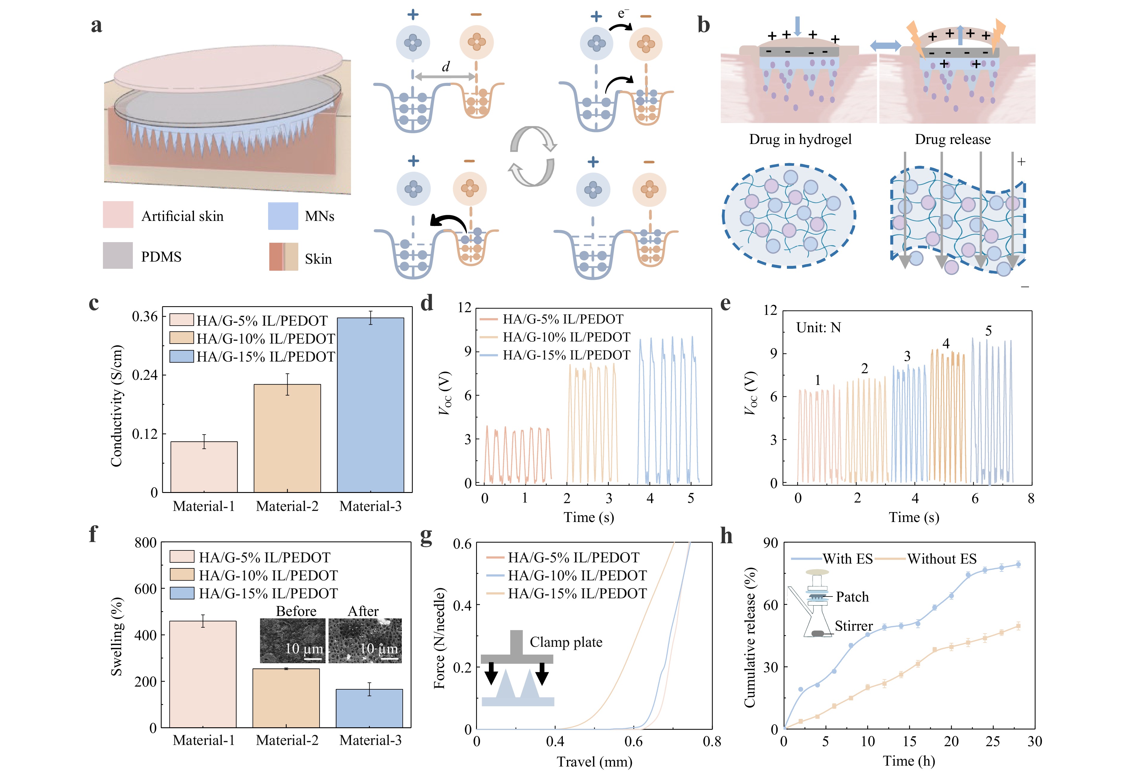
Fig. 4 ES-MNP working principle and performance characterization for enhanced transdermal drug delivery. a Schematic illustration of the ES-MNP structure and the TENG working mechanism. b Schematic of electrical stimulation leading to enhanced permeability and accelerated drug release. c Conductivity measurements of IL/PEDOT:PSS composite films at different concentrations (5%, 10%, 15%). d Open-circuit voltage output of the ES-MNP with different IL/PEDOT:PSS concentrations. e Open-circuit voltage output of the ES-MNP (HA/G-10% IL/PEDOT:PSS) under different pressures. f Swelling capability of the ES-MNPs after a 5 min-insertion into agarose hydrogel. g Mechanical compression test of the ES-MNPs. h Comparison of drug release kinetics between patches with ES and without ES. Data in c, f and h were presented as means ± SD, n = 3.
The TENG primarily consisted of a conductive layer and dielectric layer. The electrical output of the TENG was related to the intrinsic properties of these materials, particularly the conductivity of the electrode layer. Thus, optimising the IL/PEDOT:PSS composition was essential to balance conductivity and penetration capability. Electrochemical impedance spectroscopy (EIS) (Fig. S12a) and conductivity measurements (Fig. 4c) were performed on film samples with varying IL/PEDOT:PSS concentrations. The EIS results showed that the impedance of the film decreased with increasing IL/PEDOT:PSS concentration, indicating improved charge-transfer characteristics. Conductivity increased from 0.10 S/cm at 5% IL/PEDOT:PSS to 0.36 S/cm at 15% IL/PEDOT:PSS. Based on these electrical properties, the effects of IL/PEDOT:PSS concentration variation on the triboelectric performance were measured and compared (Figs. 4d and S12b). With increasing IL/PEDOT:PSS concentration, both the open-circuit voltage and short-circuit current increased, with the 15% IL/PEDOT:PSS formulation achieving an open-circuit voltage of approximately 10 V. Additionally, the ES-MNPs exhibited pressure-sensitive characteristics. As the applied pressure increased from 1.0 to 5.0 N, the electrical output increased from ~6 to ~9 V (Figs. 4e and S13). To evaluate device reliability, the output stability was assessed as a critical performance metric for high-performance TENGs. The ES-MNPs demonstrated excellent output stability (Fig. S14), maintaining a nearly equivalent performance after 1,000 contact-separation cycles. This stability is beneficial for long-term applications.
The patch swelling capacity with IL/PEDOT:PSS was evaluated using agarose hydrogel skin models and weight measurements. ES-MNPs were applied to the agarose hydrogel for 5 min, and the overall weight was measured before and after application (Fig. 4f). The comparison revealed that increasing the IL/PEDOT:PSS concentration reduced the swelling performance from approximately 450% for 5% IL/PEDOT:PSS to 160% for 15% IL/PEDOT:PSS. This occurred because the swelling capacity of the patches was dependent on their porous structure, with higher conductive material concentrations resulting in denser and less porous networks. However, the swelling capacity alone was insufficient for determining the optimal concentration, as mechanical strength is critical for effective skin penetration. Therefore, mechanical strength tests were performed. An adequate compressive strength at various concentrations was essential for effective epidermal penetration (Fig. 4g). The force–displacement curves showed the load forces sustained by the individual microneedles before the plastic bending point. The microneedle stiffness (force–displacement slope) decreased linearly with increasing IL/PEDOT:PSS concentration. This occurred because IL/PEDOT:PSS acted as a plasticiser, imparting greater flexibility to the microneedle patches. Despite the needle flexibility, the microneedle patches could withstand forces greater than 0.6 N per needle without fracture, enabling successful epidermal penetration.
After a comprehensive performance comparison, an IL/PEDOT:PSS concentration of 10% was selected for subsequent patch fabrication experiments. For the therapeutic component, ibuprofen is a commonly used non-steroidal anti-inflammatory drug (NSAID). It has anti-inflammatory, analgesic, and antipyretic properties. Dexibuprofen is an isolated S-(+)-enantiomer of racemic ibuprofen with superior therapeutic efficacy and potentially reduced side effects. Therefore, dexibuprofen was incorporated into the hydrogel to promote wound healing and reduce inflammation. The cumulative release profile was quantified to evaluate drug release performance (Fig. 4h). The microneedle patches exhibited sustained drug release over time. Both groups were subjected to identical cyclic mechanical compressions and differed only in whether the external circuit was connected. Notably, continuous ES generated through contact with the patches facilitated enhanced drug release. This increased the cumulative drug release to approximately 80% under ES conditions. The electro-responsive mechanism was validated by the significantly higher swelling ratio under ES (510% vs. 300%) and enhanced RhB diffusion in the biomimetic gelatine model (Fig. S15). These findings demonstrated that ES facilitates hydrogel network expansion and increases matrix permeability, thereby accelerating drug transport. Under drug-loaded release conditions, the electrical output of the ES-MNPs was simultaneously monitored at a compression force of approximately 1 N and remained stable over 2,000 cycles (Fig. S16). This mechanism can also be applied to other small-molecule drugs, whereas larger molecules such as growth factors may require additional hydrogel optimisation.
-
Analysis of the temperature and pH levels in wounds can provide valuable information regarding the status of wound infection. Previous studies have shown that the wound pH and temperature indicate the presence and severity of an infection. Elevated temperatures indicate bacterial infections, which typically cause redness and swelling. Infected wounds are rich in bacteria and typically have alkaline pH values. Colorimetric sensing is the ideal method for monitoring these critical parameters. It offers instrument-free visual detection, which is simple and patient-friendly. Fig. 5a illustrates the sensing mechanisms of the two colorimetric materials used for wound monitoring35,36. Temperature changes alter the molecular arrangement of cholesterol liquid crystals, altering the helical pitch and, thus, the reflected light colour. Similarly, phenol red undergoes pH-dependent protonation/deprotonation, which alters its conjugated structure and the resultant colour. Figs. 5b and S17a show the relationship between R channel intensity and pH (6.5–9.0), revealing an inverse correlation: red intensity decreased with increasing pH. For the thermochromic liquid crystal, the reflected colour shifted continuously across the visible spectrum with temperature; therefore, it was quantified using the Hue channel in the HSV colour space. The characteristic thermal response curve of the liquid crystal material was depicted through Hue channel changes from 31 to 41 °C (Figs. 5c and S17b). Based on these results, quantitative determination of the temperature and pH parameters could be achieved through image capture. Controlled image acquisition and optimised image processing maintain sensing consistency and reduce the influence of ambient lighting variations. This established the foundation for real-time, non-invasive wound infection monitoring through colorimetric analysis.
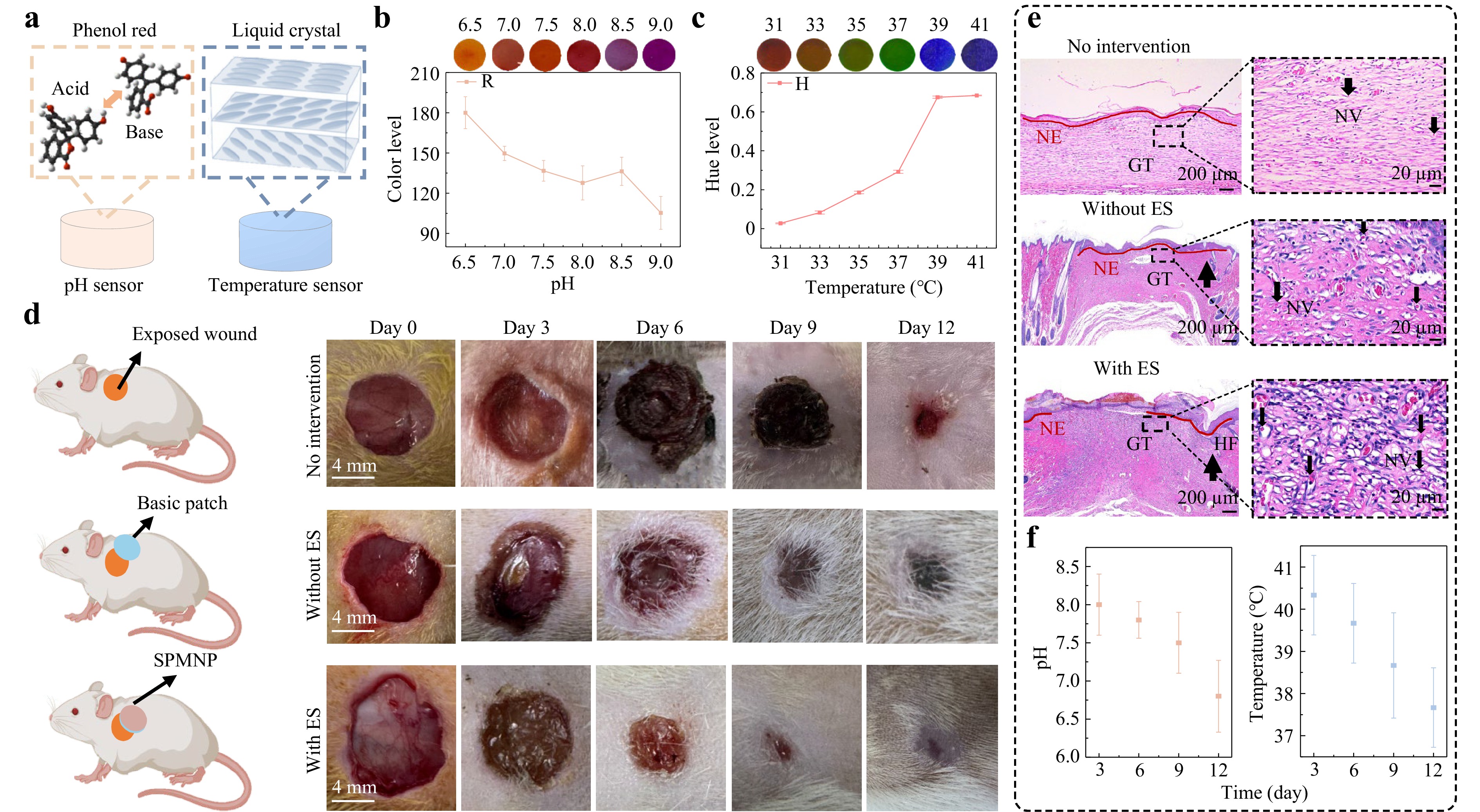
Fig. 5 Real-time colorimetric sensing and in vivo wound healing of the SPMNP. a Colorimetric sensing mechanisms for pH and temperature detection using phenol red and cholesterol liquid crystal materials, respectively. Statistical chart of colour-channel changes for b pH (R channel, RGB) and c temperature (Hue channel, HSV). d Schematic and corresponding real-time images of circular wounds cut on an SD rat's back under different treatments on days 0, 3, 6, 9, and 12, respectively. e H&E staining reveals wound healing structures: new epithelium (NE), granulation tissue (GT), and hair follicles (HF). Magnified images show new vessels (NV) within granulation tissue. Markers indicate NE (red lines), GT (black rectangles), HF (up arrows), and NV (down arrows). f Temperature and pH levels of wounds during the healing process. Data in b, c, and f were presented as means ± SD, n = 3.
The two colorimetric components were integrated into the microneedle patch to construct an SPMNP (Fig. S18). Given its importance in practical applications, patch biocompatibility was evaluated before application. The material cytotoxicity was investigated through in vitro cell experiments using CCK-8 assays performed every 12 h to monitor changes in cell viability (Fig. S19a). The cell proliferation rates of all the experimental groups gradually increased over time, indicating normal cellular growth. Cell viability staining revealed that all the experimental groups maintained a relatively high living cell density, comparable to that of the control groups, with almost no dead cell fluorescence detected (Fig. S19b). Collectively, these results demonstrated that the SPMNP components exhibited excellent biocompatibility.
Chronic wound healing requires sustained therapeutic drug delivery, and the controlled drug release capability of the SPMNP makes it suitable for chronic wound healing. To validate its wound-healing potential, circular incisions with an 8 mm diameter were created on the dorsal region of rats. The rats were randomly divided into three groups: a blank group without intervention, a sample group with a basic patch, and a sample group with a patch incorporating ES functionality (Fig. 5d). Wound-healing images were recorded on days 0, 3, 6, 9, and 12 to monitor healing progression16,37. SPMNP-treated wounds showed accelerated tissue regeneration, reduced inflammation, and rapid wound closure. On day 12, the SPMNP group demonstrated significantly superior healing, with minimal scarring and nearly complete wound closure. In contrast, the other groups showed visible wound areas and slower healing processes (Fig. S20a). Quantitative analysis of the healing rate (Fig. S20b) further validated these observations, showing that SPMNP-treated wounds achieved a significantly higher daily area reduction, particularly during the peak healing phase (days 3–6), compared with the control and basic patch groups. The wound-healing effect in the SPMNP group was superior to that in the other groups. In the SPMNP group in particular, the healing rate in the first 6 days was ~200% and ~50% faster than that in the other groups. Haematoxylin and eosin (H&E) staining showed that re-epithelialisation was most evident in the SPMNP group, with the newborn epithelium (NE) showing the maximum extension (Figs. 5e and S21). Compared with the other groups, more neovascularization (NV) and hair follicles (HF) were observed, indicating robust tissue regeneration and restoration of normal skin architecture. To assess the real-time wound status, we monitored the temperature and pH values in the SPMNP group using colorimetric sensors over 12 days (Fig. 5f). During the early wound-healing stage, the temperature and pH levels were elevated, indicating that the wound was in the infection stage. As the infection symptoms subsided and healing progressed, these indicators gradually returned to normal levels. These trends matched those of wound recovery and validated colorimetric sensors for biomedical applications. In summary, these findings demonstrate that the SPMNP provides an effective approach for chronic wound management and monitoring.
-
A CO2 laser defocusing strategy was developed for a controllable fabrication of microneedle moulds. This enables the rapid customisation of different wound morphologies. This method achieved tip diameters as small as 2.2 μm with superior flexibility and reproducibility. A self-powered microneedle patch (SPMNP) was developed using precisely fabricated moulds. The SPMNP-integrated TENG technology converts body movements into bioelectrical signals. These signals modulate hydrogel permeability for ES-triggered drug release. ES enhances the drug release efficiency to 80% compared with passive delivery. Embedded colorimetric sensors provide real-time monitoring of the wound pH and temperature through visible colour changes. This eliminates the requirement for complex electronic readout systems. The same approach can be extended to other biomarkers such as glucose, lactate, and matrix metalloproteinases, broadening the diagnostic scope of the platform. In vivo experiments using rat wound models demonstrated significantly accelerated healing. The multifunctional SPMNP exhibited excellent biocompatibility and therapeutic efficacy. The SPMNP was validated in an acute model, but its features are ideal for treating chronic wounds. It combines sustained drug release, ES, and continuous monitoring. These functions are essential when natural healing is impaired and long-term therapy is required. Although this study provided significant proof-of-concept evidence, future optimisation will involve larger animal cohorts to further validate the long-term clinical potential. This integrated platform addresses the critical challenges in chronic wound management. It simultaneously achieved high-precision customisable fabrication, self-powered therapeutic delivery, and intuitive continuous monitoring. This approach has a broad potential for personalised biomedical applications.
-
Polydimethylsiloxane (PDMS, Sylgard 184) was obtained from Dow Corning (Midland, IL, USA). Sodium hydroxide (NaOH) was purchased from Aladdin (Shanghai, China). 1,4-butanediol diglycidyl ether (BDDE, 98%), phenol red (95%), rhodamine B, and hyaluronic acid sodium (Mw:100,000−200,000 Da) were obtained from Heown (Tianjin, China). Gelatine was purchased from Haoqixin (Hangzhou, China). PEDOT:PSS (1.0 to 1.3 wt% solid content, PH 1,000) and the ionic liquid (4-(3-butyl-1-imidazolio)-1-butanesulfonic acid triflate) were purchased from Clevios and Dibai (Shanghai), respectively. Dexibuprofen, methylene blue hydrate, and tetrahydrofuran (>99.9%) were purchased from Macklin (Shanghai, China). Cholesteryl oleyl carbonate (COC), cholesteryl nonanoate (CN), and cholesteryl 2,4-dichlorobenzoate (CD) were purchased from Adamas (Shanghai, China).
-
First, 200 μL of BDDE was added to a beaker containing 10 mL of NaOH solution (0.25 mol/L) and mixed thoroughly to prepare the crosslinking agent solution. Sodium hyaluronate powder (1 g) was added to the crosslinking agent solution. The mixture was incubated at 40 °C for 2 h to ensure adequate mixing and cross-linking. Subsequently, gelatine particles were introduced into the mixture at a mass ratio of 1:2 (gelatine: mixture). The solution was neutralised to approximately pH 7 by dropwise addition of 0.1 mol/L HCl to terminate the crosslinking reaction. The crosslinked HA/G mixture was filtered and washed with deionised water to remove the residual BDDE and unreacted HA. To eliminate the numerous air bubbles present in the crosslinked HA hydrogel, we performed homogenisation at 1,500 rpm for 90 s using a high-speed mixer. Finally, the cross-linked HA/G hydrogel was loaded into syringes for subsequent use.
-
Fabrication of the microneedle moulds using different laser parameters. A laser beam drilled holes in 2 mm-thick PDMS sheets to fabricate microporous templates. The PDMS prepolymer and curing agent were mixed (10:1 ratio) and vacuum degassed for 20 min to remove air bubbles. The mixture was cured in a custom mould at 80 °C for 2 h. The PDMS sheet was then peeled off the mould. A CO2 laser system (VLS2.50, UNIVERSAL Laser System Inc.) was used to drill holes into the PDMS sheet surface and generate the microcavities. The high-magnification focusing lens had a minimum spot diameter of 0.001 inch and a focal depth of 0.03 inch. The low-magnification focusing lens had a minimum spot diameter of 0.003 inch and a focal depth of 0.075 inch. Circular patterns were used for laser engraving at a fixed laser speed of 127 mm/s, laser power of 12–24 W, and PPI values ranging from 500 to 900. The defocusing distance ranged from −0.5 to 0.3 mm for the high-magnification focusing lens and from −1 to 1 mm for the low-magnification focusing lens.
Fabrication of the MNP. The hydrogel was extruded from the syringe and spread onto the surface of the PDMS template. Vacuum treatment followed at −0.1 MPa for 5 min at room temperature (~25 °C) to remove air bubbles and fill needle tips with hydrogel. After vacuum processing, the template was dried on a heating stage at 60 °C for 1 h. After complete drying, the microneedles were demoulded from the PDMS template to obtain the microneedle patches.
-
The surface morphologies of the MNPs fabricated under different conditions were observed using SEM (Gemini300, ZEISS, Germany). The optical images of the surfaces were captured using a metallurgical microscope (MCK-6RC, Caikon). The mechanical strengths of the fabricated microneedle patches were determined using a tensile testing machine (FSA-0.5K2-500 N, IMADA). The tested microneedles were placed on the test platform with the needle tips facing upward, and a load was applied vertically to the needle tips. The magnitude of load sustained by the microneedles was recorded. The force per needle was calculated by dividing the total force applied by the number of needles.
-
Incorporation of conductive material and drug in the MNP. The PEDOT:PSS aqueous solution was filtered through a 0.45 µm syringe filter and stirred for 30 min. An ionic liquid (80 wt%) was added to the prepared PEDOT:PSS aqueous solution, followed by vigorous stirring for 10 min. The ionic liquid content was calculated based on the solid content of PEDOT:PSS in the solution. The solid content of PEDOT:PSS was calculated to be 1 wt%. A mixed IL/PEDOT:PSS solution was added during HA/G hydrogel crosslinking at 5%–15% by mass of the hydrogel. For drug loading, dexibuprofen powder was incorporated at 0.05% relative to the total mass of the conductive hydrogel and homogenised for 120 s.
Fabrication of the ES-MNP. The mixed hydrogel was cast onto the surface of the PDMS template. The template was placed in a convection drying oven at 40 °C overnight to preserve the bioactivity of dexibuprofen. After complete drying, demoulding was performed to obtain dexibuprofen-loaded microneedle patches. The PDMS prepolymer and curing agent were mixed at a weight ratio of 10:1 and poured into a sheet mould with dimensions matching those of the microneedle patch. After curing at 80 °C for 2 h, the sheet was peeled off and attached to the bottom of a microneedle patch. Artificial skin of the same size was cut and attached to the PDMS.
-
Mixed films (5%, 10%, and 15%) were produced by spreading the patch mixture on a smooth surface. For EIS measurements, the film served as the working electrode (WE), Ag/AgCl was used as the reference electrode (RE), and Pt was used as the counter electrode (CE). All electrodes were immersed in phosphate-buffered saline (PBS) as an aqueous medium, and measurements were performed using an electrochemical workstation (CHI760E, CH Instruments). The film thickness was measured using a thickness gauge (BCT-210C, Botech Co., Ltd.). Electrical resistance was measured using a digital multimeter (catalogue no. 34461A, Keysight). The output triboelectric signals of the ES-MNP were measured and collected using a programmable electrometer (6514, Keithley, USA) and a data acquisition system (National Instruments, USA). LabVIEW was used to record and analyse the signals collected from the experiments, providing real-time data acquisition and monitoring for further analysis. During testing, a linear motor (J-5718 HBS 401, Yisheng, China) was used to provide cyclic mechanical excitation to the ES-MNP. A tensile testing machine (FSA-0.5K2 500 N, IMADA) was used to apply various forces and conduct mechanical strength testing.
-
To evaluate the kinetics of drug release from the MNP, we used a transdermal diffusion apparatus to conduct transdermal absorption experiments. The receiving chamber was filled with PBS, and a skin-like dressing served as a diffusion membrane on the chamber surface. The dexibuprofen-loaded ES-MNP was applied to the membrane and secured with medical tape. The diffusion chamber was placed on top, and the device was clamped using positioning clips. A sealing film was applied to the upper outlet to prevent water loss. The water bath temperature was set to 37 °C, and the magnetic stirrer speed was set to 350 rpm to simulate a transdermal drug delivery environment closer to in vivo conditions. At designated time points, 3 mL of the solution was withdrawn from the receiving chamber and stored in centrifuge tubes, and fresh PBS buffer was immediately added to the receiving chamber. After all sampling was completed, the dexibuprofen content in the samples was determined by UV-visible spectrophotometry (PerkinElmer Lambda 950, USA). For ES-MNP testing with ES, a linear motor cyclically compressed the patch against the synthetic skin. The release efficiency was determined as the ratio of the cumulative release at different time points to the drug-loading amount:
$$ {Q}_{n}=\dfrac{V{C}_{n}+\displaystyle\sum\limits_{i=1}^{n-1}{V}_{i}{C}_{i}}{M}\times 100\% $$ where V is the volume of the receiving pool, Cn is the drug concentration of sample n, Vi is the liquid volume of sample i, Ci is the drug concentration of sample i, and M is the drug loading amount. To visualise the ES-driven diffusion process, we prepared a tissue-mimetic model by solidifying a 10 wt% gelatine solution in a Petri dish via controlled heating and cooling. RhB-loaded MNPs were inserted into the gelatine matrix, and the diffusion behaviours with and without ES were monitored. Additionally, the dynamic swelling ratios of the hydrogel patches were measured under identical mechanical compression (1 N) to quantify ES-induced network expansion.
-
Fabrication of colour display sensors. The cholesterol derivatives COC, CN, and CD were mixed at a weight ratio of 30:40:30. The liquid crystal mixture was dissolved in tetrahydrofuran, and an appropriate amount was coated on the PDMS template. Heating at 70 °C completely evaporated the tetrahydrofuran. This allowed the liquid crystal mixture to be deposited on the PDMS film for visual characterisation. For the pH sensor, phenol red was dropped onto the PDMS template and dried in an oven.
Fabrication of the SPMNP. Two colorimetric sensor units were cut according to the template shape and placed at the corresponding positions on the PDMS film. The film with the colorimetric sensors was positioned to cover the bottom of the drug-loaded conductive microneedle patch with empty slots. An artificial silicone skin layer was placed at the top.
-
The pH measurement procedure consisted of two steps. Solutions with different pH values (6–9) were prepared by adjusting the deionised water with NaOH and HCl, which were then verified using a pH meter. For colour quantification, 10 μL of each solution was applied to a pH colorimetric sensor. Images were captured, and RGB values were extracted to analyse the quantitative relationship between the pH and sensor colours. For temperature detection, cholesterol liquid crystal-coated PDMS film was placed on a heating platform (31–41 °C). During the temperature changes, images of the thermochromic PDMS film were captured using a digital camera, and the RGB values were extracted. The quantitative relationship between the temperature and sensor colour was then analysed.
-
NIH/3T3 fibroblasts were obtained from the Chinese Academy of Sciences. The cells were revived, cultured, and sub-cultured until a stable growth state was achieved. Material extracts were prepared in a serum-free medium for subsequent cell viability testing. Stably growing 3T3 fibroblasts were digested with trypsin, centrifuged, and resuspended in an appropriate volume of medium. Cells were counted using a haemocytometer, and 20,000 cells were seeded in each well of a 24-well plate. After complete cell adhesion, the first CCK-8 assay was performed and recorded at 0 h. Subsequently, the original medium in each well was replaced with the respective extracts (IL/PEDOT:PSS, phenol red, liquid crystals, and CT). The control group was treated with serum-free medium. CCK-8 assays were conducted at 12-h intervals. The optical density (OD) of each well was measured at each time point. The OD values of the blank (medium only) wells were subtracted from the OD readings of the experimental wells. The corrected OD values were averaged within groups and plotted over time to evaluate cell viability trends.
-
Specific pathogen-free (SPF) male Sprague (SD) rats (180−220 g) were obtained from Hangzhou Joinn Laboratory Biotechnology Co., Ltd. All the animal procedures were approved by the Animal Care and Use Committee of the Second Affiliated Hospital of the Zhejiang University School of Medicine (No. ZJU20240573). Animals were housed in a controlled environment at 23 ± 1 °C with 50 ± 10% relative humidity under a 12 h light/12 h dark cycle with free access to food and water. Rats were acclimated to the housing facility for one week before experimentation to minimise stress.
-
Under anaesthesia, healthy SD rats were subjected to dorsal fur removal using an electric clipper and depilatory cream. Full-thickness excisional wounds (8 mm diameter) were created on the dorsal skin. The animals were randomly assigned to one of the three groups. The control group received no treatment, the conventional dressing group was treated with drug-loaded microneedle patches without TENG integration, and the with ES group received drug-loaded electrostimulation microneedle patches with integrated TENG. Wound images were captured on days 0, 3, 6, 9, and 12. In the MNP group, the outer fixation film was temporarily lifted at each time point to expose the colorimetric sensors to digital imaging under standardised lighting conditions. This was followed by the application of a fresh patch to ensure continuous therapy. The animals were euthanised on day 12 and wound tissues were collected for histological examination. The percentage of remaining wound area was determined by normalising the wound area at each time point to the initial wound area.
-
Surgically treated animals recovered under strictly monitored conditions and received proper postoperative care, including pain management and wound care, to promote healing. On day 12 after wound creation, wound tissues were collected after euthanasia for histological analysis. The collected tissue samples were fixed in 4% formaldehyde solution for 24 h to preserve the cellular structure and prevent degradation. After fixation, the tissues were carefully dehydrated through alcohol solutions to remove any water content. Tissue samples were embedded in molten paraffin wax at a controlled temperature to ensure that the tissue was thoroughly infiltrated with paraffin for optimal preservation. Samples were sectioned to examine the treated tissues. The sections were cut to a thickness of approximately 10 μm, which allowed for a detailed examination of the tissue morphology under a microscope. For histological examination, slices were stained with H&E after cleaning with distilled water.
-
All experimental data were statistically analysed and presented as the mean ± standard deviation (SD), with a sample size of n ≥ 3 for each group. Error bars represented the SD. One-way analysis of variance was used to determine the statistical significance of differences. Data were processed and analysed using Microsoft Excel and Origin 2018.
-
This work was supported by the National Natural Science Foundation of China (U25A20321 and 52475610) and the Zhejiang Provincial Natural Science Foundation of China (LDQ24E050001 and LR26E050002).
Defocused laser-induced self-powered microneedle patches for drug-releasing and wound monitoring
- Light: Advanced Manufacturing , Article number: 116 (2026)
- Received: 06 March 2026
- Revised: 30 June 2026
- Accepted: 01 July 2026 Published online: 29 October 2026
doi: https://doi.org/10.37188/lam.2026.116
Abstract: Chronic wound management requires integrated platforms that combine precise drug delivery, therapeutic stimulation, and continuous monitoring. However, existing microneedle techniques encounter challenges in simultaneously achieving high-precision fabrication, self-powered stimulation-responsive release, and real-time physiological monitoring. In this study, a laser defocusing strategy was developed that utilises energy density variations and plasma shielding effects to enable controllable microneedle mould fabrication. Negative defocusing positions the CO2 laser focal point below the material surface, where the concentrated Gaussian energy distribution enhances the thermal ablation. The plasma shielding effects confine the ablation zone, enabling precise tip formation as small as 2.2 μm. By leveraging this fabrication platform, we created a self-powered microneedle patch for electrical stimulation-triggered drug release, increasing the cumulative amount to approximately 80%. Integrated colorimetric sensors enable the real-time monitoring of wound temperature and pH. In vivo studies demonstrated significantly accelerated wound healing. Through functional integration, this patch fulfils the clinical needs of chronic wound management, making it suitable for personalised therapeutic applications.
Research Summary
Laser defocusing: Fabricating size-tunable, self-powered microneedle patches
Chronic wounds that resist healing are hard to manage, because they need drug delivery, therapeutic stimulation and continuous monitoring at the same time. Kaichen Xu at Zhejiang University in China and colleagues now report a microneedle patch that combines all three. The team aimed a carbon-dioxide laser just below a material's surface, where the concentrated Gaussian energy intensified thermal ablation and produced moulds with tips only a few micrometres wide. Patches cast from these moulds generate their own electricity, using it to trigger drug release on demand and raising delivery efficiency to 80%. Built-in colour-changing sensors track wound temperature and pH in real time. In animal studies, the patches markedly sped up healing. This compact, self-powered design could support personalised care for difficult chronic wounds.
Rights and permissions
Open Access This article is licensed under a Creative Commons Attribution 4.0 International License, which permits use, sharing, adaptation, distribution and reproduction in any medium or format, as long as you give appropriate credit to the original author(s) and the source, provide a link to the Creative Commons license, and indicate if changes were made. The images or other third party material in this article are included in the article′s Creative Commons license, unless indicated otherwise in a credit line to the material. If material is not included in the article′s Creative Commons license and your intended use is not permitted by statutory regulation or exceeds the permitted use, you will need to obtain permission directly from the copyright holder. To view a copy of this license, visit http://creativecommons.org/licenses/by/4.0/.

 DownLoad: