


-
Gabor invented holography in 1948, attempting to correct the spherical aberrations of the electron microscope1. Based on Gabor’s idea, the light field information including the amplitude and phase distributions could be retrieved by recording the interferogram of the object and reference waves. However, owing to the lack of highly coherent light sources and bottleneck of separating the twin images in the on-axis holography, holography did not receive serious attention at that time. With the invention of the high coherence laser and proposal of off-axis holography2, holography has since developed rapidly. However, limited by the complex physical and chemical processing of photographic plates or films, conventional holography has faced difficulties in real-time measurements. In 1967, Goodman introduced electronic-based imaging methods into hologram-recording and computer technologies into the image reconstruction3. Subsequently, digital holography was developed to realise the dynamic and quantitative measurement of different samples with high efficiency4. Based on diffraction theory, it was determined that the object light field could be numerically reconstructed using the digitally diffracted light wave from the digital hologram “illuminated” with a simulated reference light wave.
A potential problem of digital holography is that the mismatch between the numerically simulated reference wave and experimentally used one could induce reconstruction errors such as phase aberration. Hence, different numerical methods were developed to address this problem5. Based on the double-exposure principle, digital holographic interferometry (DHI) can eliminate phase aberration through the phase subtraction of the object waves reconstructed by the holograms with and without the sample. Exploiting the capability of measuring physical parameters associated with the object wave phase, DHI has been applied to visualising different complex flow fields6 such as Karman vortex street in water flow7, temperature distribution of heat conduction process8, solution concentration variation9, liquid diffusion process10, sound pressure distribution11, pulse laser ablation process12, and sound waves13. In Fig. 1a−d, four examples are displayed.
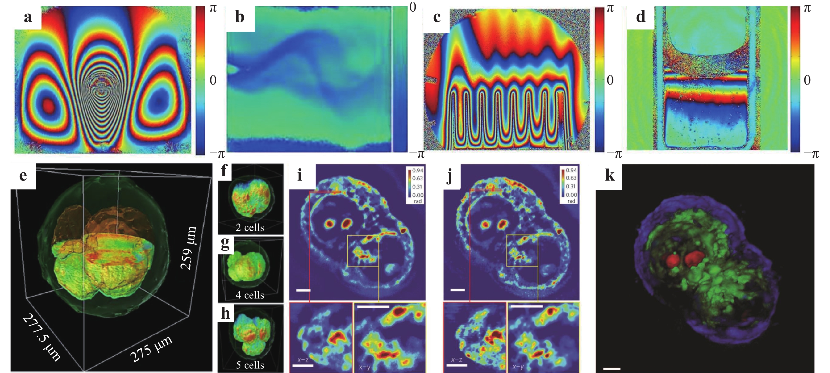
Fig. 1
Applications of DHI in visualising complex flow fields: a thermocapillary motion of a droplet6, b Karman vortex street7, c heat dissipation process of a heat sink8, and d protein-lysozyme solution crystallisation process9. Applications of DHT in 3D biomedical imaging: e an embryo cut through the centre and f−h different development stages of bovine embryos14. Measurement results of HT29 cells15: i Z-slice (top), cross-section of the region marked by the red box (bottom left) and enlargement of the region marked bythe yellow box (bottom right), j deconvolved results of i, and k 3D rendering of the deconvolution result. Scale bars: 5 μm. Images reprinted with the following permissions: a6, b7, d9 from The Optical Society; c8 from AIP; e−k14 from Springer Nature.In principle, the reconstructed object image can be numerically focused at any position16 for flexible microscopic imaging. Therefore, by combining digital holography with optical microscopy, digital holographic microscopy (DHM) has become a popular phase imaging method for semi-transparent and transparent (weak scattering) or reflective phase objects. Upon the reflection by the sample surface or transmission through the sample, the phase distribution of the probing beam carries the information of the sample’s profile or refractive index (or thickness), respectively. Consequently, DHM enables high-contrast imaging of small specimens as well as quantitative characterisation of the three-dimensional (3D) morphology and refractive index. Owing to the advantages of label-free, non-contact, and wide-field measurement, DHM and its derivatives have found wide application in industrial inspection, biomedical research, and other fields in the past decades17. However, the phase information obtained by DHM is an integral along the light propagation direction. To acquire the information inside the test specimen, digital holographic tomography (DHT) has achieved rapid progress and different approaches have been proposed to realise tomographic measurement14,15,18. We display two application examples of DHT in Fig. 1e−k. In addition, 3D phase and fluorescence images have been simultaneously obtained using a coherent and incoherent integrated common-path DHM system19.
Another fundamental problem of digital holography is resolution improvement. Similar to other wide-field optical imaging modalities, the spatial resolution of digital holography is restricted by the spatial resolution of the imaging device and also obeys Abbe’s diffraction limit20. To improve the imaging resolution, numerous approaches such as oblique illumination21,22, synthetic aperture23,24, structured illumination25, and speckle illumination26 have been introduced27. To further promote the application of digital holography, advanced computation techniques, for example, deep learning, have been introduced in digital holography for numerical reconstruction28−31, fast image autofocusing32,33, phase unwrapping34, phase aberration compensation35, and other uses. Deep learning has also been combined with digital holography to achieve additional functionality such as screening of anthrax spores36, classification of cell morphology37, and viral particle detection and classification38.
Regarding the experimental configurations of digital holography and its derivatives, two basic types, namely in-line (on-axis, coaxial) and off-axis geometries are typically used. In-line geometry39−41 can fully use the camera bandwidth and phase shifting techniques can be used to remove the zero-order frequency component of the hologram42. To address the time-consuming problem in the phase-shifting operation, different parallel phase-shifting approaches have been developed43−46. However, the corresponding experimental configurations are typically complex and not easily aligned. Therefore, off-axis geometry is more frequently considered, especially for practical instrument constructions. For traditional holographic interferometry, off-axis configurations based on Mach–Zehnder and Michelson interferometers are commonly established for (semi-) transparent and reflective test objects, respectively. Based on these two interference models, a Swiss company, Lyncée Tec SA (https://www.lynceetec.com/) pioneered the commercialisation of digital holographic microscopes and is leading this instrument industry. They have invented different types of microscopes that can be applied in dynamic topography, living cell imaging, MEMS testing, automated measurements, and other areas. Another company from the Republic of Korea, Tomocube (http://www.tomocube.com/), invented holotomographic microscopes based on the principle of DHT to measure the 3D refractive index distributions of biological cells and thin tissues. Our group has also been working on the instrumentation of off-axis holographic experimental setups, including instruments for measuring both large-size and microscopic objects. Fig. 2a−c are the transmission, reflection, and transmission and reflection integrated digital holographic microscopes invented by our group, respectively. Among these, the one in Fig. 2c was built based on the mechanical structure of an inexpensive commercial microscope, making it easy to build and cost-effective.
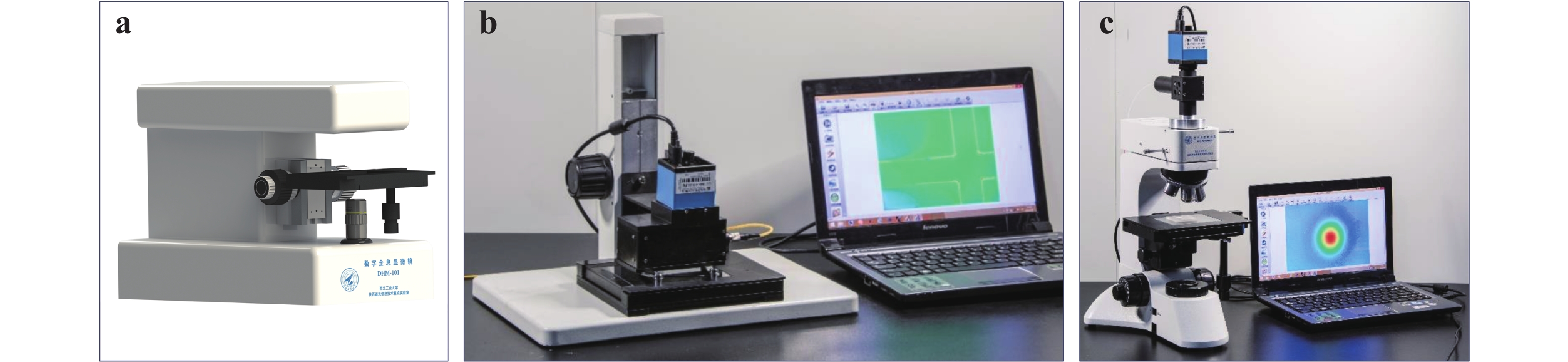
Fig. 2
a Transmission, b reflection, and c transmission and reflection integrated digital holographic microscopes invented by our group.In general, the object and reference beams in an off-axis holographic configuration interfere via separated paths to form the hologram. Consequently, any mechanical vibration or air disturbance, even marginal, can cause different influences on the two separated interference beams. This induces phase noise and results in low temporal stability. If the object and reference beams propagate along the same path in a common-path configuration47, the environmental disturbance on the two interference beams can be effectively compensated with significantly enhanced temporal stability. In addition, the compact and robust common-path configuration is advantageous in optical instrument manufacturing. In this review, we summarise the design principle of the common-path off-axis digital holographic setups and present examples of their applications, providing a prospect in high stable optical instrument manufacturing.
-
First, we outline the basic principle of off-axis digital holography48. As indicated in Fig. 3a, the object beam carrying the object information and reference beam, which is typically a uniform plane wave, interfere on the CCD camera with an appropriate angle. For simplicity, we assume that the object beam propagates along the y-axis and the optical axis of the reference beam has an angle of θ relative to the y-axis. The complex amplitudes of the two beams on the hologram-recording plane can be expressed as
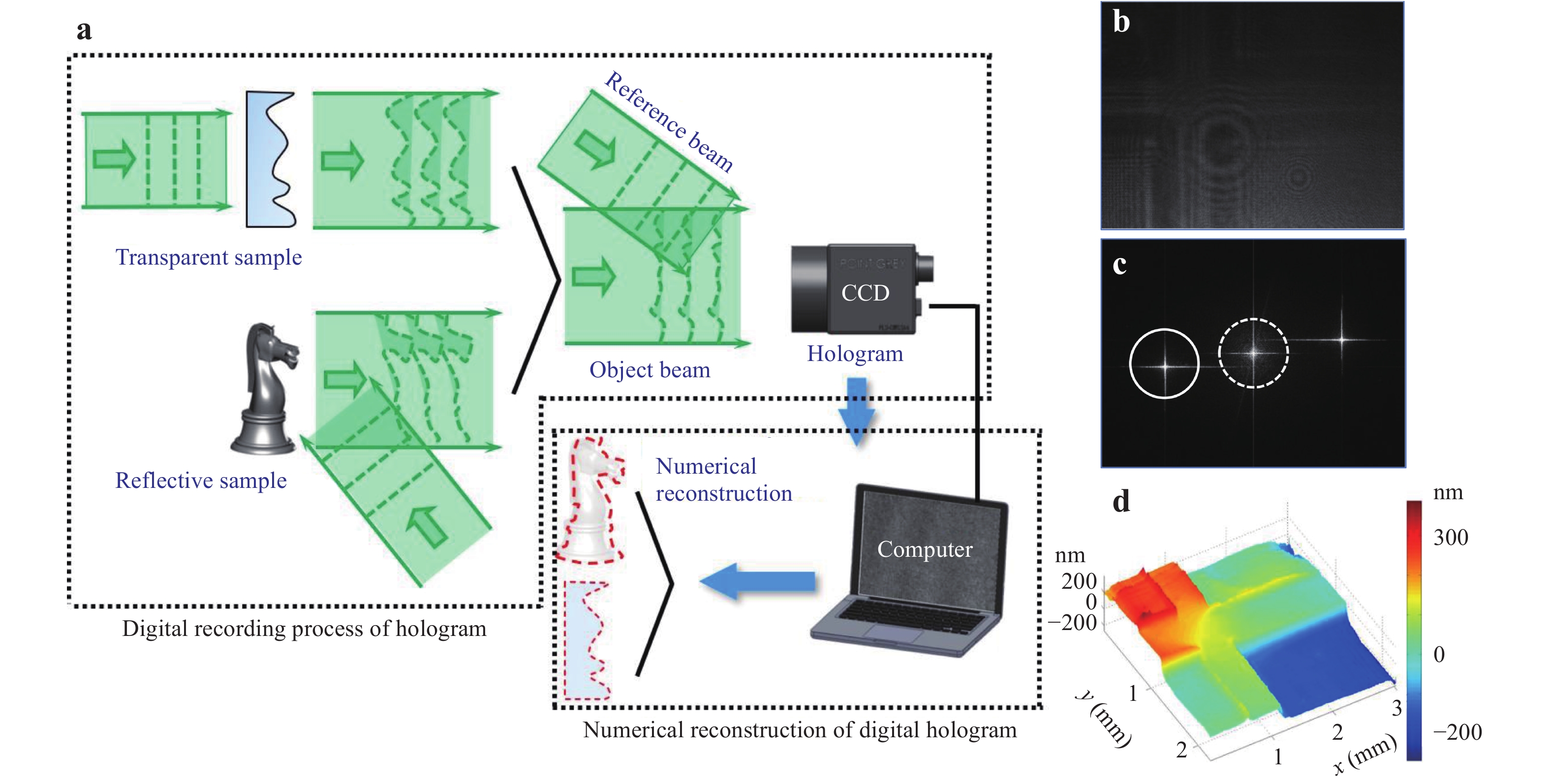
Fig. 3
a Operating procedure of off-axis digital holography. Coherent light beam passing through transparent samples or reflected by reflective samples acts as the object beam. The object and reference beams interfere with each other on the CCD with a small angle to form the off-axis digital hologram. b Hologram recorded by off-axis digital holography. c Fourier transform of the hologram in b. d Reconstructed 3D height profile of a stair-structured sample.$${e_O}\left( {x,y} \right) = {a_O}\left( {x,y} \right)\exp \left[ {{\rm{j}}{\phi _O}\left( {x,y} \right)} \right]$$ (1) $${e_R}(x,y) = {a_R}(x,y)\exp \left( {{\rm{j}}2{{\text π }}\frac{{\sin \theta }}{\lambda }y} \right)$$ (2) where, aO(x, y) and aR(x, y) are the amplitudes and ϕO(x, y) is the phase distribution of the object wavefront. The intensity distribution of the hologram, i.e., the interferogram between the two beams (see example in Fig. 3b) is
$$\begin{aligned}[b] I(x,y) =& {\left| {{e_O}(x,y) + {e_R}(x,y)} \right|^2} = {\left| {{e_O}(x,y)} \right|^2} + {\left| {{e_R}(x,y)} \right|^2} +\\& {e_O}(x,y)a_R^*(x,y)\exp \left( { - {\rm{j}}2{{{\text π } }}\frac{{\sin \theta }}{\lambda }y} \right) +\\& e_O^*(x,y){a_R}(x,y)\exp \left( {{\rm{j}}2{{{\text π } }}\frac{{\sin \theta }}{\lambda }y} \right) \\ \end{aligned} $$ (3) For reconstruction, the conjugate of the original reference beam
$e^*_R $ (x, y) is used to illuminate the hologram. The diffraction includes four parts:$$\tag{4a}{U_1}(x,y) = Te_R^*(x,y){\left| {{e_O}(x,y)} \right|^2}$$ $$\tag{4b}{U_2}(x,y) = Te_R^*(x,y){\left| {{e_R}(x,y)} \right|^2}$$ $$\tag{4c}{U_3}(x,y) = Te_R^*(x,y){e_O}(x,y)a_R^*(x,y)\exp \left( { - {\rm{j}}2{\rm{{\text π } }}\frac{{\sin \theta }}{\lambda }y} \right)$$ $$\tag{4d}{U_4}(x,y) = Te_R^*(x,y)e_O^*(x,y){a_R}(x,y)\exp \left( {{\rm{j}}2{\rm{{\text π } }}\frac{{\sin \theta }}{\lambda }y} \right)$$ where T is the average transmission of the reconstruction wave passing through the hologram. Eq. 4a and 4b denote the 0th order diffraction components and Eq. 4c and 4d denote the separated twin images due to the carrier frequency of the reference beam. For numerical reconstruction of the object wave, the Fourier transform-based convolution method is typically used. The ±1st order Fourier spectra of the hologram corresponding to Eq. 4c and 4d are separated in the Fourier space. The circles in Fig. 3c mark the 0th and 1st order Fourier spectra of the hologram in Fig. 3b. Because only the term in Eq. 4c contains the original object information eO(x, y), it can be reconstructed through properly selecting the 1st order spectral component in the Fourier space.
The complex amplitude of the diffraction wave carrying the object information at position z = d from the hologram plane can be expressed as
$$\begin{aligned}[b] u\left( {{\xi ^\prime },{\eta ^\prime }} \right) = &\int_{ - \infty }^\infty {\int_{ - \infty }^\infty {{U_{\rm{3}}}} } (x,y){g_{{\rm{PSF}}}}\left( {x - {\xi ^\prime },y - {\eta ^\prime }} \right){\rm{d}}x{\rm{d}}y \\ =& {U_{\rm{3}}}(x,y) * {g_{{\rm{PSF}}}}\left( {{\xi ^\prime },{\eta ^\prime }} \right) \\ \end{aligned} $$ where the symbol “*” denotes the convolution calculation and gPSF(ξ', η') is the point spread function (PSF), which can be expressed as
$${g_{{\rm{PSF}}}}\left( {{\xi ^\prime },{\eta ^\prime }} \right) = \frac{{\rm{j}}}{\lambda }\frac{{\exp \left( { - {\rm{j}}{k_0}\sqrt {{d^2} + {\xi ^{\prime 2}} + {\eta ^{\prime 2}}} } \right)}}{{\sqrt {{d^2} + {\xi ^{\prime 2}} + {\eta ^{\prime 2}}} }}$$ (6) Based on the convolution property of the Fourier transform, the reconstructed object wave can be expressed as
$$u\left( {{\xi ^\prime },{\eta ^\prime }} \right) = F_{x,y}^{ - 1}\left[ {{F_{x,y}}\left( {{U_{\rm{3}}}} \right){F_{x,y}}\left( {{g_{{\rm{PSF}}}}} \right)} \right] \equiv F_{x,y}^{ - 1}\left[ {{F_{x,y}}\left( {{U_{\rm{3}}}} \right){G_{{\rm{PSF}}}}} \right]$$ (7) where the operations “
${F_{x,y}}$ ” and “$F_{x,y}^{ - 1}$ ” denote the two-dimensional Fourier transform and inverse Fourier transform, respectively, and GPSF is the Fourier transform of gPSF and acts as the transfer function of the imaging system. Taking the discrete forms, the reconstruction can be performed digitally. Fig. 3d displays the calculated 3D height profile of a stair-structured sample from the hologram in Fig. 3b.To record the off-axis hologram, the object beam must interfere with a uniform reference beam at a certain angle. The key issue to design a common-path configuration is to generate a uniform reference beam allowing the two interference beams to pass along similar paths. The greater the level of similarity, the greater the stability of the optical setup. From the perspective of the approach to generate the reference beam, we categorise the common-path models as lateral shearing, point diffraction, and other types.
-
The lateral shearing interferometer was invented to measure the asphericity of an optical wavefront49. The wavefront under test is first doubled using specific optical elements and the two wavefronts create a lateral shear or displacement. The overlapping area of the two wavefronts forms the interferogram for further analysis. The two wavefronts propagate along similar paths, which inspires the design of lateral shearing-based common-path configurations for off-axis digital holography. The concept of lateral shearing-based off-axis digital holography is illustrated in Fig. 4. The illumination beam passes through a (semi-) transparent sample (or is reflected by an opaque sample) and an imaging system. A beam duplicator reproduces the beam into two beams that are projected on the CCD target at a proper angle. Note here that both beams carry the same sample information. However, as discussed in the previous section, a uniform reference beam containing no sample information is required for the hologram formation. Therefore, the test sample in the lateral shearing-based common-path configuration must be sparse in the field of view (FOV), or only a portion of the beam illuminates the sample. In this manner, the effective interference area, i.e., the overlapping area of the two beams with and without the sample information, can be realised. This feature is different from that of a traditional lateral shearing interferometer.
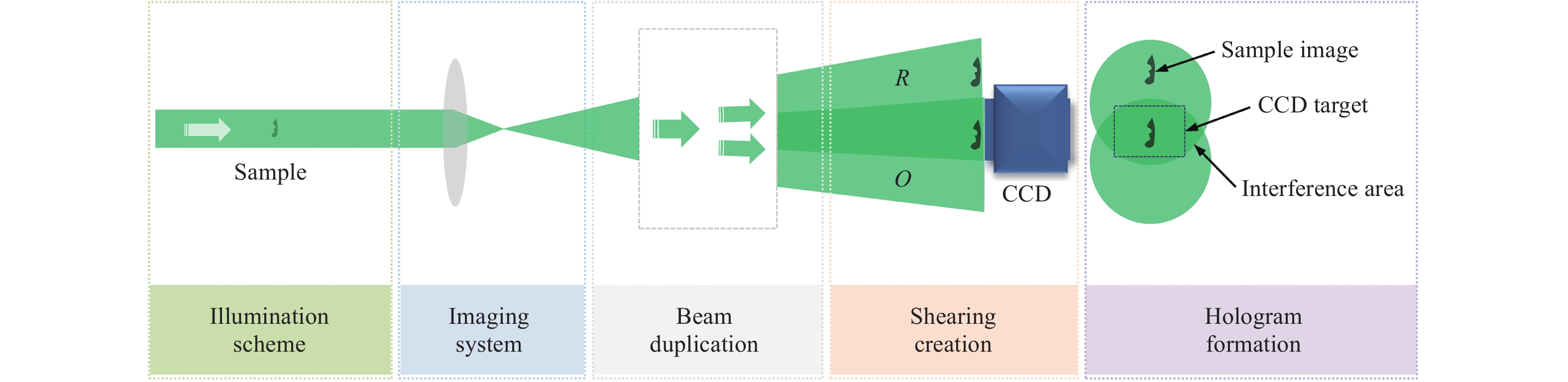
Fig. 4 Concept of common-path configuration based on lateral shearing interference.
-
Multiple optical components such as glass plate50−53, grating54−58, and beam splitter (BS)59−62 are typically employed as the beam duplicator in the lateral shearing-based common-path configurations. Fig. 5 displays an example using a glass plate50. A plane wave passing through the sample is expanded by a microscope objective (MO) to become a divergent beam. The beam is then reflected at the front and back surfaces of a glass plate oriented at approximately 45° relative to the optical axis of the beam. Consequently, the incident beam is doubled to create a lateral shearing, as indicated in Fig. 5(a). The two beams are divergent satisfying the recording condition of the off-axis geometry. This configuration can be easily integrated with a commercial microscope for practical applications. Glass microspheres were used as the test samples. The hologram was recorded when only one sphere appeared in the FOV. The height of the sphere surface d = ϕλ/ (2πΔn) was retrieved from the phase image, where ϕ is the phase value, λ is the light wavelength, and Δn is the index difference between the sample and its surrounding media. Fig. 5b displays the retrieved height distribution of the sphere surface. Note here that the seemingly “two” spheres with positive and negative heights are displayed in the image. In fact, it represents the information of the same sphere. Two spheres appear in the FOV because the beam is reflected twice by the glass plate, and the bending direction of the interference fringes of the left sphere is opposite to that of the right sphere. The duplicated image can limit the effective FOV of this experimental setup. To address this problem, the illumination beam size must be sufficiently large such that the object size is smaller than the interference area and only one copy of the object information is imaged onto the CCD target. Fig. 5c displays the 3D height profile of the sphere surface on the right side of Fig. 5b, and the inset indicates the corresponding cross-sectional profile.
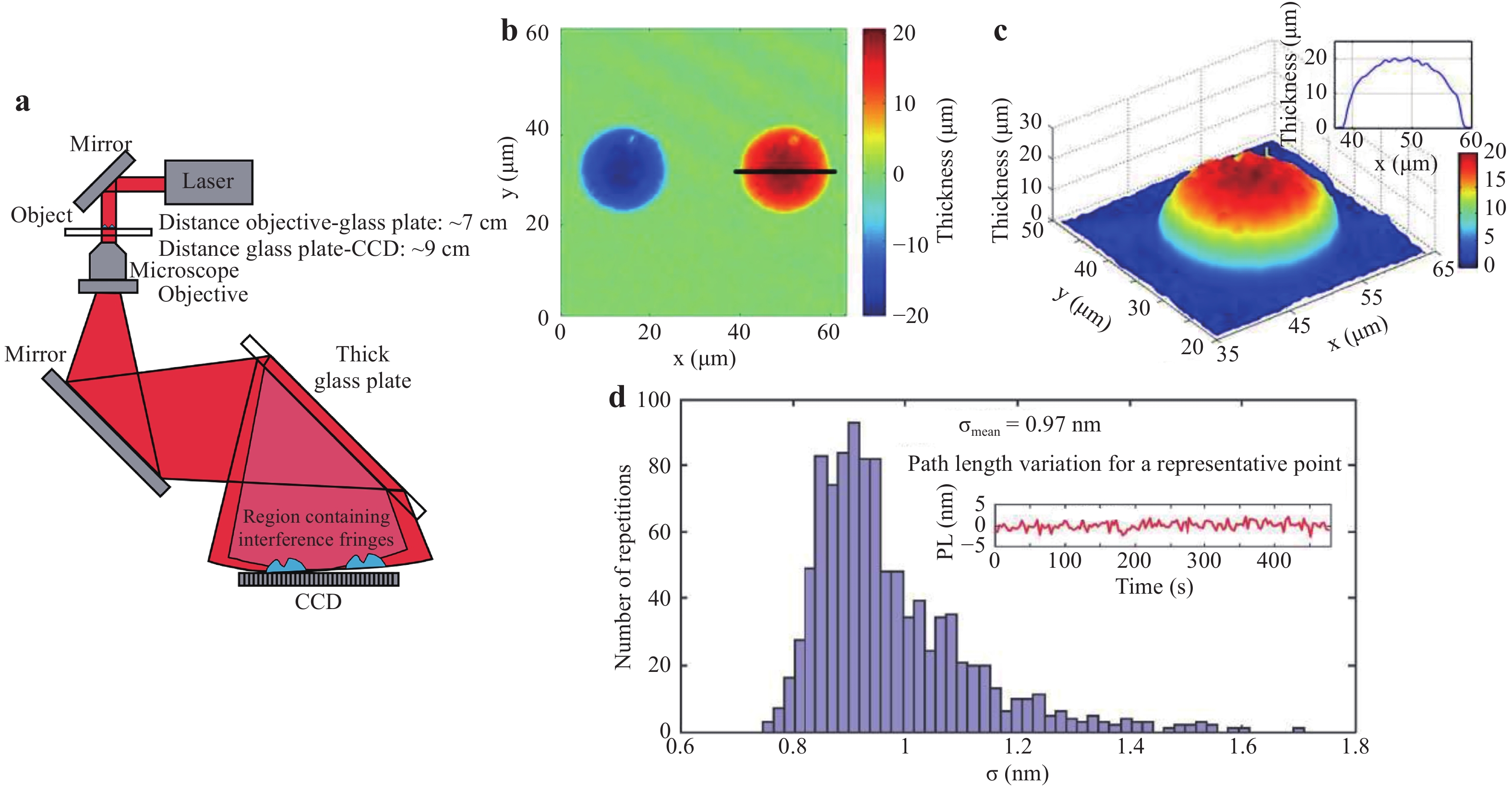
Fig. 5
a Experimental setup of common-path DHM based on lateral shearing using a glass plate. b Retrieved height distribution of the sphere surface. c 3D and cross-sectional thickness profile of the sphere on the right side of b. d Histogram for the standard deviations of fluctuations50. Images reprinted with the permission from The Optical Society.The common-path holographic configuration can improve the temporal stability of the setup, especially the phase measurement stability of the object wave. The stability characterisation should be performed without vibration compensation. Using the setup in Fig. 5a as an example, 1200 holograms without objects were recorded over an area of 37.5 μm × 37.5 μm at a speed of 2.5 frames per second for 8 minutes. Phase images of all the holograms were reconstructed and the optical path difference was obtained by subtracting the phase values with that of the previously recorded hologram. Then, 1024 pixel positions were randomly selected in the FOV and the standard deviations of the fluctuations of these positions were calculated. Fig. 5d displays the histogram of the fluctuations with an average value less than 1 nm at a wavelength of 632.8 nm. This indicates an optical path fluctuation of only 0.01 rad. This small fluctuation demonstrates the high temporal stability of the experimental setup.
Based on the lateral shearing-based common-path configuration using a glass plate, researchers developed a compact structured-illumination-based DHM setup53. By illuminating the sample with structured intensity patterns, the imaging resolution of the amplitude- and phase-contrast images can be effectively enhanced. This design reduces the complexity of the setup and provides high temporal stability.
-
In the previous glass plate-based configuration, the divergent beam from the MO reaches the CCD target without an imaging lens. The object cannot be directly imaged on the hologram-recording plane and thus it needs to set an appropriate reconstruction distance. To record the image plane hologram, alternative optical components can be employed. Fig. 6 displays an example of using a grating as the beam duplicator58. A plane wave illuminates the sample. The transmitted beam is expanded by an MO and then passes through an imaging tube lens TL, by which the sample is imaged on the image plane IP. A grating G is placed at a distance z after the IP to reproduce multiple replicas of the sample image. Then, the intermediate sample images are projected onto the camera target via a 4f unit with lenses L1 and L2. During this process, a mask B for spatial filtering is placed at the Fourier plane of lens L1, such that only the 0th and +1st diffraction orders can pass through it. These two orders are Fourier transformed again by lens L2 to produce lateral shearing interference (shearing distance l) and form an off-axis image plane hologram. This lateral shearing module can also be integrated with a commercial inverted microscope.
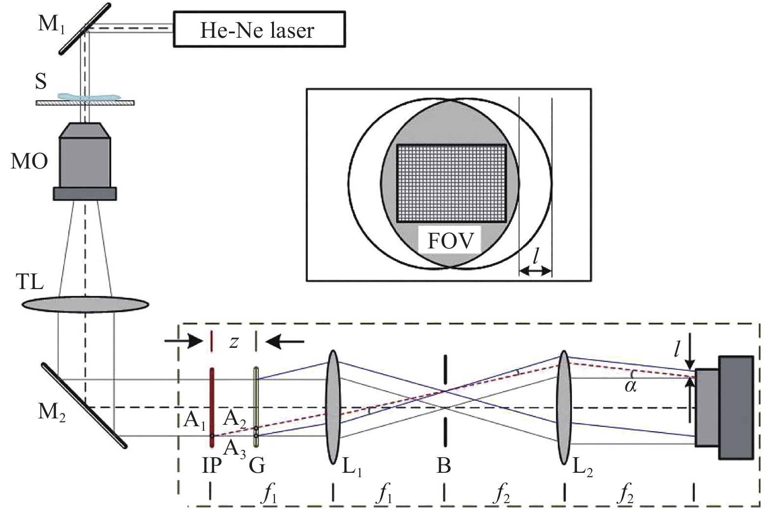
Fig. 6 Experimental setup of common-path DHM based on lateral shearing using a 4f imaging unit and diffraction grating58.
M1, M2: mirrors, S: sample, MO: microscope objective, TL: tube lens, IP: image plane, G: diffraction grating, L1, L2: lenses, B: mask for spatial filtering. Image reprinted with the permission from The Optical Society.In general, there is a tradeoff between the FOV and off-axis angle that should be balanced in practical applications. Conversely, in the common-path configuration of Fig. 6, the off-axis angle is solely determined by the grating period d and focal lengths of lenses L1 and L2, i.e., α=f1λ/ f2d. The shearing distance l=f2λz / f1d is dependent on the distance z, which can be adjusted by moving the grating along the optical axis freely. Consequently, the off-axis angle related to the interference fringe frequency is not required to match the shearing distance. The flexible selection of the shearing distance does not lose the spatial frequency of the sample.
In addition to the one-dimensional grating, a specific two-dimensional grating has been applied to create four replicas of the object image. Combining the setup in Fig. 6 with multiplexing techniques, researchers have recorded a polarisation hologram and reconstructed the wavefronts of two orthogonally polarised components containing the sample information using a single camera shot55,51.
-
A single BS can also be employed to construct lateral shearing-based common-path DHM configurations59−62. The output beam from a microscopic imaging system contains the half-object and half-reference parts. Then, the entire beam is further divided by a BS to create the sheared beams. Finally, the half-object and half-reference beams interfere with each other at a certain angle. Using the setup in Fig. 7a, which uses a slight trapezoid Sagnac interferometer and was developed by our group60 as an example, a polarised BS (PBS) splits the object beam into two counter-propagating components with orthogonal polarisation states. The two components pass through the identical optical elements and then reach the CCD target. The off-axis recording condition can be achieved by marginally rotating the PBS with the transmitted p-polarised component maintaining the propagation direction perpendicular to the CCD target. Consequently, the p-polarised component acts as the object beam, whereas the s-polarised component contains no sample information and serves as the reference beam. A polariser P2 is used before the CCD to modulate the fringe contrast of the hologram. Note that the functionality of the BS used here is different from that in the Mach–Zehnder and Michelson interferometer-based setups. The two interference beams in Fig. 7a pass along the same paths, ensuring the high temporal stability in the configuration. To verify its high temporal stability compared with that of a Mach-Zehnder interferometer-based configuration, a similar characterisation method with that of Fig. 5d was used. The results demonstrated that the mean phase fluctuation of the common-path setup and Mach-Zehnder interferometer was 0.011 rad (Fig. 7b) and 0.106 rad, respectively. That is, the temporal stability of this common-path configuration was approximately one order of magnitude greater than that of the uncommon-path interferometer configuration. Owing to the high stability, we monitored a water evaporation process that has wide application in microfluidics, surface self-cleaning, and other areas63. Moreover, two static measurements were also experimentally demonstrated. The first was a pit on a silica glass damaged by high-power laser irradiation. The retrieved pit depth is displayed in Fig. 7c. The other was a living Hela cell, which is in the human cervical cancer cell lines. The reconstructed quantitative phase image of the cell is displayed in Fig. 7d.
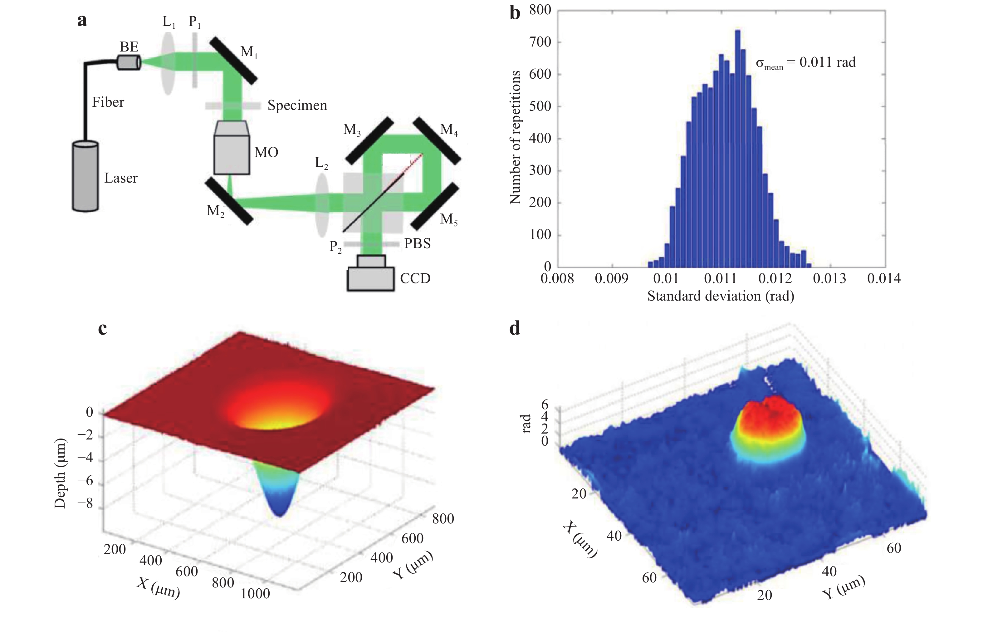
Fig. 7
a Typical experimental setup of lateral shearing-based common-path DHM using a BS60. b Histogram of standard deviation of the common-path setup in a. c 3D topography of a pit ablated by high-power laser irradiation. d Quantitative phase image of a Hela cell. Images reprinted with the permission from The Optical Society.Other special optical components such as beam displacer64, Wollaston prism (WP)65, Rochon polariser66, gradient-index lens67, and biprism68 can also be utilised in the lateral shearing-based common-path configurations to construct compact and stable holographic experimental setups.
-
In the lateral shearing-based common-path off-axis holographic experimental setups, sparse samples in the FOV or undisturbed portion of the illumination beam are required. Moreover, it has a potential problem of a duplicated image appearing on the camera target if the shearing distance is not sufficiently large, which could limit its practical applications. Alternatively, another common-path model referred as diffraction phase microscopy (DPM) was developed by Gabriel69.
As discussed in the previous section, the key issue to design a common-path configuration is to generate a uniform reference beam allowing the two interference beams to propagate along the same or similar paths. Here, we introduce the principle of generating the reference beam using the point diffraction model. As depicted in Fig. 869, a magnified sample image is obtained in an inverted microscope. To illustrate the imaging process, we start from a virtual point source (VPS) representing the object plane. At the image plane (IP), a grating G replicates the microscopic image and generates several diffraction orders. Then, the diffractions enter into a 4f unit with lenses L1 and L2. The 0th order beam is low-pass filtered by a pinhole at the focal plane of L1, resulting in a uniform reference beam. Simultaneously, one of the 1st order beams containing complete sample information passes through the unit and becomes the object beam. Finally, the two beams interfere with each other on the CCD target at an appropriate off-axis angle. As this common-path configuration generates the uniform reference beam by diffracting the object beam through a “point” pinhole, we call this model the “point diffraction model”. Unlike the typical Mach–Zender interferometer, here the interference beams pass through the identical optical elements, ensuring high temporal stability. The average standard deviation of the optical path length in the full FOV was measured as 0.7 nm at a wavelength of 532 nm and the temporal standard deviation was 0.04 nm69. Similar to the lateral shearing-based common-path configurations, the common-path module in Fig. 8 can also be integrated with a commercial microscope.
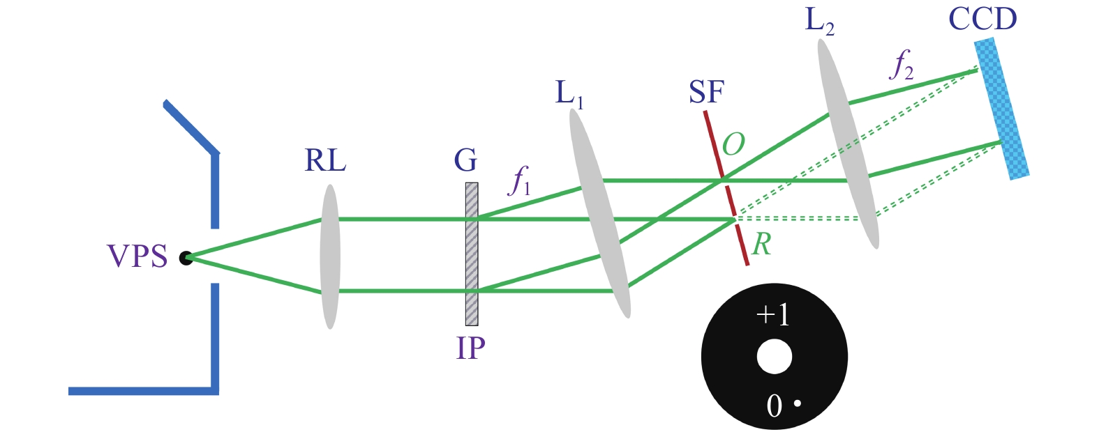
Fig. 8 Basic configuration of point diffraction-based common-path off-axis digital holography69.
VPS: virtual point source, RL: relay lens, G: grating, IP: image plane, L1,2: lenses, SF: spatial filter. -
The module in Fig. 8 using a grating for beam duplication, however, has a low utilisation efficiency of the light power and is also somewhat bulky as a 4f unit is included. Hence, alternative designs have been proposed to realise the point diffraction70−72. For example, a so-called τ interferometer is mounted at the output port of a microscope (Fig. 9a)73. This interferometer reproduces the object beam using a cubic BS and two mirrors reflect the beams. The pinhole is pasted on one of the mirrors to eliminate the sample information and create a uniform reference beam. The triangular interferometer-based setup in Fig. 9(b) also uses a cubic BS for the beam duplication, however, the pinhole is implemented in the transmission mode74. A biprism can effectively double the object beam, not only compatible in the lateral shearing-based but also in the point diffraction-based common-path configurations (Fig. 9c)75. Unlike the former configurations, a digital micromirror device (DMD)-based setup reproduces the uniform beam before passing through the sample, as depicted in Fig. 9d76. A DMD positioned at the conjugate plane of the MO’s back-aperture plane generates two plane waves for the illumination. Moreover, a glass plate, typically used in a lateral shearing-based configuration with a limited FOV, can also reproduce the object beam in the point diffraction-based configuration with high utilisation efficiency of the light power77.
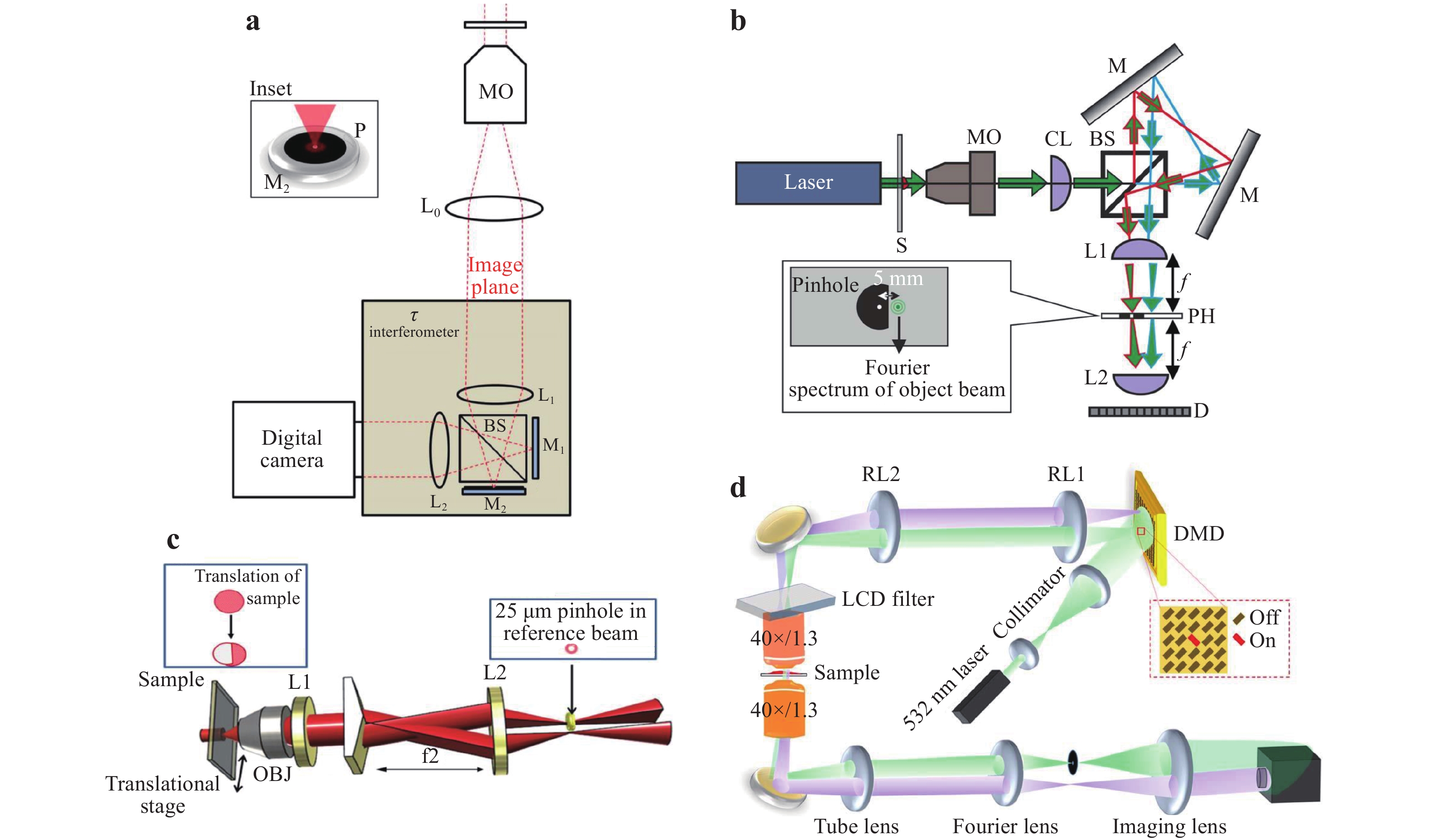
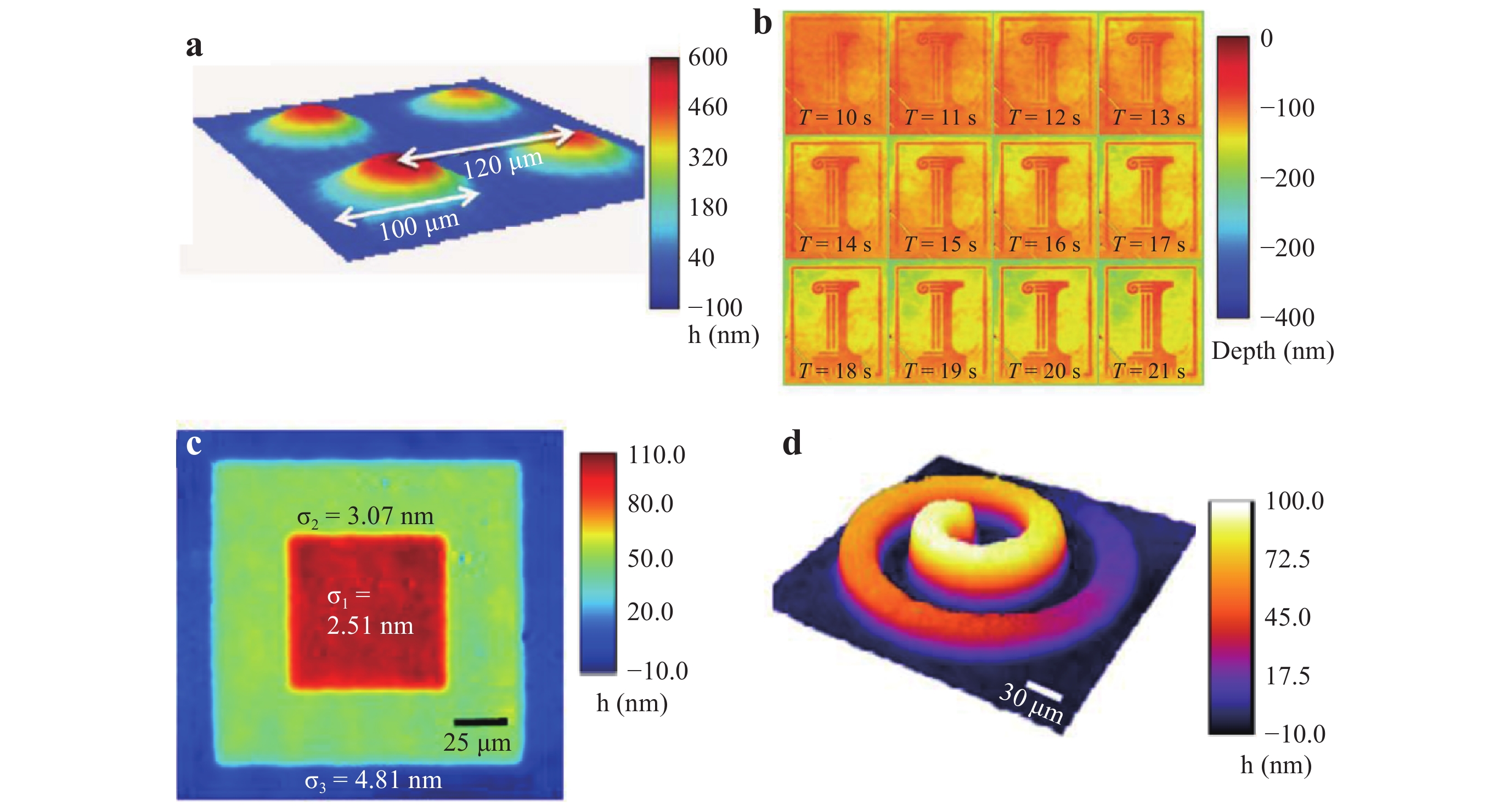
Owing to the high stability and compact features, the point diffraction-based common-path DHM has been widely used in biological studies, material science applications, and other applications78. For example, the thickness distribution of a 2 × 2 array of microlenses was measured, as displayed in Fig. 10a. In addition, researchers have constructed a DHM setup that operates in reflection mode for opaque samples and dynamically monitored nanoscale topographic changes during semiconductor etching. Fig. 10b displays the reconstructed logo of the University of Illinois when a GaAs wafer was being etched with a solution79. Fig. 10c and 10d present the measured topography images of a multi-step stair structure and Archimedean spiral, respectively80.
-
Speckle noise caused by the high coherence of lasers can typically contaminate reconstructed object images, resulting in a decrease of the phase measurement sensitivity and limiting the capabilities of investigating samples with subcellular features. Hence, white light illumination with low coherence is applied in point diffraction-based common-path DHM to decrease the spatiotemporal noise effectively15,81,82. The corresponding setup is developed from that in Fig. 8, as indicated in Fig. 11a82. One of the differences is that a low-coherent halogen lamp with a condenser is used for the illumination. By closing down the condenser aperture to the minimum, the entire illumination field is spatially coherent. Another difference is that digital masks on a spatial light modulator (SLM) perform the spatial filtering to generate the object and reference beams. This common-path configuration makes the optical path difference between the object and reference beams extremely small, such that the two beams are coherent and can interfere with each other regardless of the wavelength used. In addition to the SLM, a liquid crystal display device has also been applied to provide the digital filter masks83.
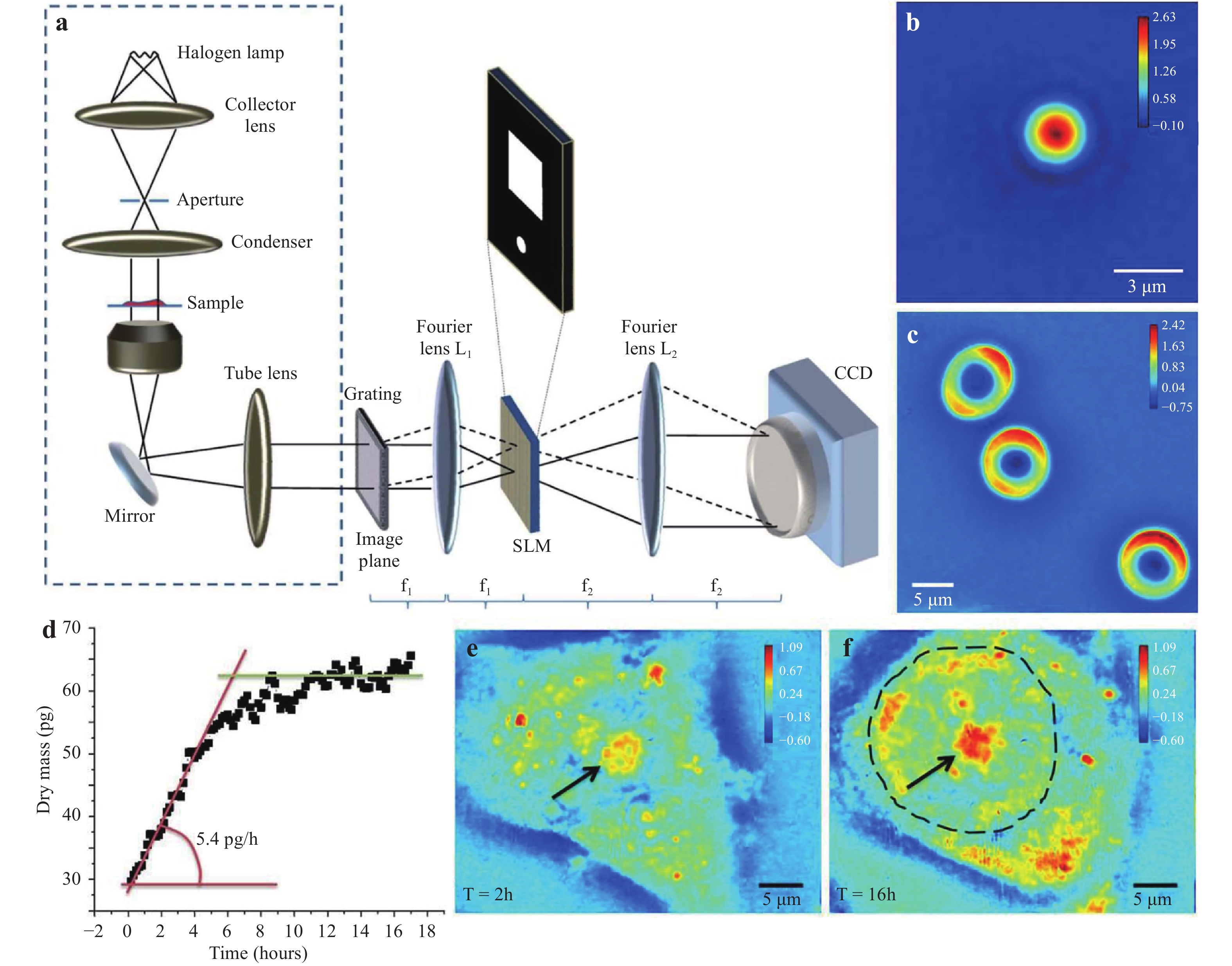
Fig. 11
a Experimental setup of point diffraction-based common-path DHM using white light illumination82. Reconstructed phase images of b a polystyrene bead and c live RBCs. d Variations of the dry mass for a HeLa cell during its growth. Quantitative phase images of the test HeLa cell at a time of e 2 hours and f 16 hours. All of the colour bars represent the phase in radians81. Images reprinted with the permission from The Optical Society.The white light illumination-based setup exhibits high temporal stability owing to the common-path configuration and high phase measurement sensitivity due to the low-coherent illumination. It has found wide applications in the biomedical field including red blood cell (RBC) membrane fluctuation measurement81, cardiomyocyte cell beating measurement, and cell growth study84. In the following, we provide application examples. Fig. 11b displays the reconstructed phase image of a polystyrene bead. Fig. 11c displays the phase image of three live RBCs where the typical discocyte shapes are clearly present. It can be observed that the phase background of the image is considerably uniform owing to the low coherent illumination. Moreover, the growth of Hela cells was monitored. The dots in Fig. 11d indicate the variations of the cell’s dry mass with time. It can be observed that the test cell grows rapidly in the first six hours. Then, its growth slows and finally saturates. Fig. 11e−f are the phase images of the test cell at a time of 2 hours and 16 hours, respectively. As indicated by the arrows, the cell nucleolus in Fig. 11f is becoming larger than that in Fig. 11e.
Regardless of whether the illumination is laser-based or white light-based, each type has its advantages and disadvantages. It was found that laser-based illumination is superior for material science applications where the samples have fine structural features or sharp edges. Conversely, white light-based illumination is more advantageous in biological applications where the sample features are smooth. Moreover, researchers have recently developed an endoscopic phase microscope85 that combines a gradient-index-lens-based endoscope probe with a point diffraction-based common-path module, and allows single-cell-level resolution phase imaging. This instrument has broadened the application fields of quantitative phase imaging and has demonstrated significant potential in on-site studies.
The common-path configurations discussed above use a single laser or white light source, which cannot attain the distribution of a spectroscopic object light field. However, in transmission DHM, the measured phase information of the sample is proportional to the optical thickness, which is the integral product of the sample thickness and index. Owing to this dual dependence, the thickness and index information of the sample is ambiguous. Hence, more than one measurement is required to decouple these two physical parameters. By performing two measurements with different surrounding media, the thickness and index of the sample could be retrieved through a decoupling procedure86. However, the sample state could be disturbed if the surrounding medium is changed. Alternatively, measuring phases of the object wave at different wavelengths can address this problem based on the dispersion property of the surrounding medium87. For example, spectroscopic phase microscopy has been introduced in point diffraction-based common-path DHM configurations88−90.
-
Apart from the two types discussed above, other advanced designs have also been proposed to construct common-path off-axis holographic experimental setups91.
-
One example uses a self-referencing Lloyd’s mirror configuration. As indicated in Fig. 12a, the laser beam passing through the sample is first expanded via an MO. Then, a mirror folds a part of the divergent beam onto the CMOS target. The straight propagating beam carrying the object information and unperturbed reflection beam interfere with each other to form the off-axis hologram92. This DHM setup is compact, portable, stable, and easy to implement. Its temporal stability was measured to be approximately 0.9 nm without any vibration compensation, making it suitable for monitoring the changes of a cell profile. Fig. 12b displays an experiment result of the thickness profile of RBCs.
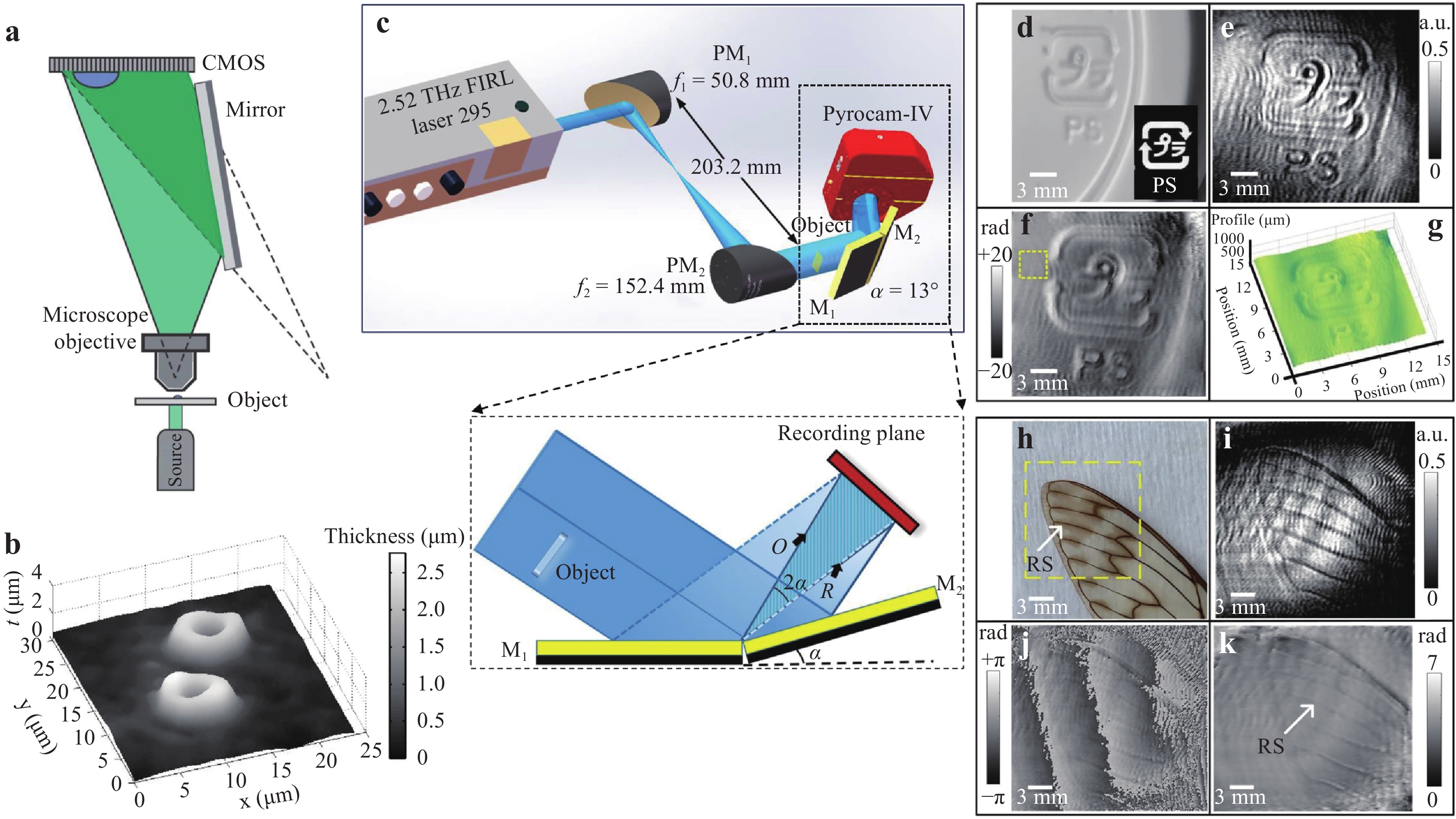
Fig. 12 Experimental setups of common-path digital holography using folding mirrors and their applications92,93.
a Setup using a Lloyd’s mirror. b Thickness profile of RBCs using the setup in a. c Setup for CW-THz self-referencing digital holography. d−g Experiment results of measuring a polystyrene cup lid: d photo of the sample, reconstructed e amplitude-contrast image, f unwrapped phase-contrast image, and g calculated 3D thickness profile. h−k Experiment results of measuring a cicada forewing: h photo of the sample, reconstructed i amplitude-contrast image, and j wrapped and k unwrapped phase-contrast image. Images reprinted with the permission from The Optical Society.Fig. 12c displays a similar design applied in continuous-wave terahertz (CW-THz) holography93. The inset indicates that the sample is illuminated by a half part of the terahertz wave. A pair of mirrors (M1 and M2) with an angle of α reflect the entire wavefront into two beams with an angle of 2α. Because the two beams are created from the same wavefront, their power and path length are virtually the same, forming interference patterns with high contrast. Unlike digital holography with visible light illumination, terahertz digital holography is a viable candidate for measuring optically opaque samples. Using the common-path setup in Fig. 12c, a polystyrene cup lid and biological samples such as insect wings are measured. The experiment results are presented in Fig. 12d−g and 12h−k, respectively.
-
Another example uses a single BS cube positioned in a special manner94−96. Fig. 13a presents an experimental setup of DHI based on total internal reflection (TIR)97 to dynamically measure the refractive index distribution of liquid samples. The sample is located at a half part of the prism surface. Only one portion of the reflected beam carries the sample information, the other acts as the reference beam. The entire beam is incident on a BS cube with the semi-reflecting layer marginally inclined relative to the optical axis. The object beam transmits through the layer and the reference beam is reflected. The off-axis angle of the two interference beams is controlled by rotating the BS. The usage of a single BS cube creates a symmetrical common-path configuration. The spherical phase curvature of the illumination beam can be compensated physically by the reference beam during the interference. Owing to the advantages of this common-path holographic configuration, we built a prototype instrument of this setup using the 3D printing technology, as displayed in Fig. 13b−c. This instrument is compact with a total physical length of only 25 mm (Fig. 13c). More importantly, it possesses high measurement stability for on-site applications.
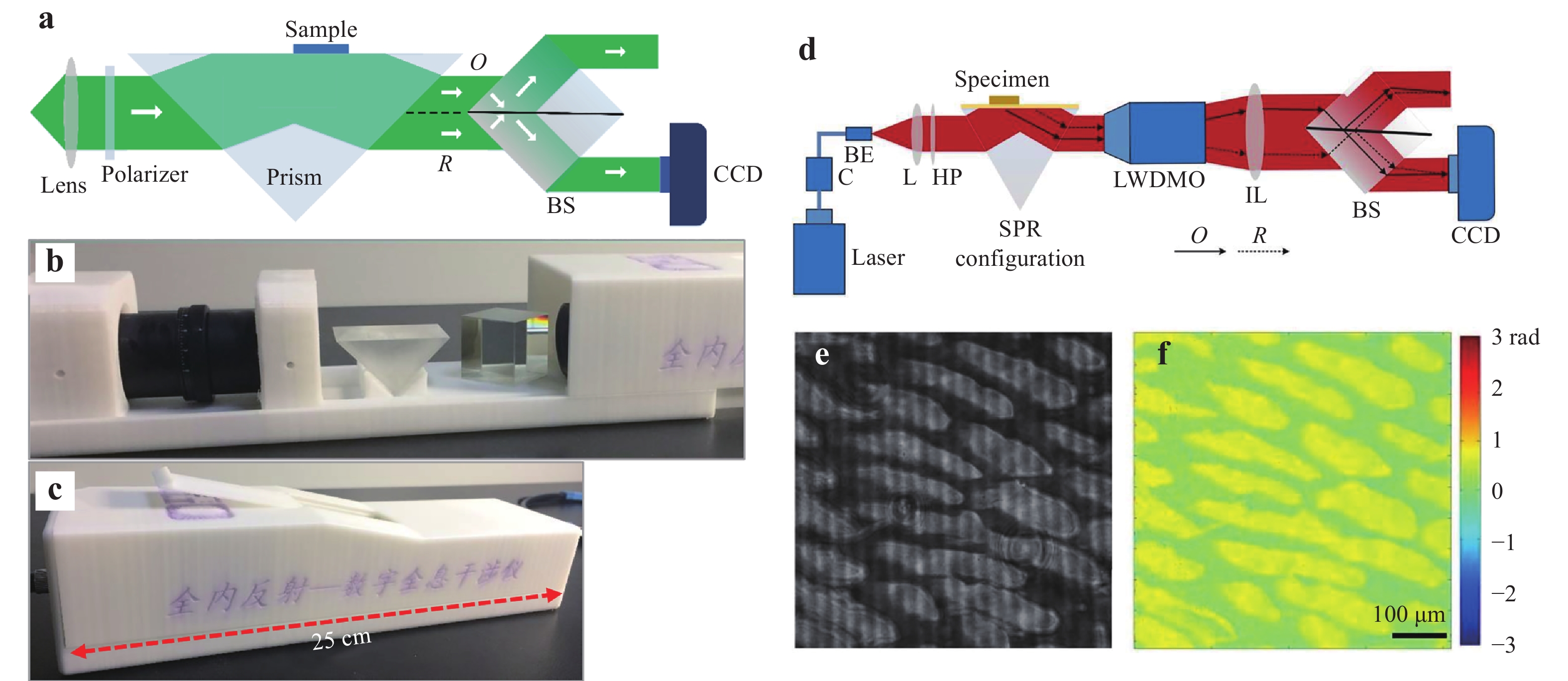
Fig. 13
a Common-path DHI setup based on TIR. b, c 3D-printed prototype instrument of the experimental setup in a. d Experimental setup of common-path DHM based on prism-coupling SPR94. C: fiber coupler, BE: beam expander, L: lens, HP: half-wave plate, LWDMO: long working distance microscope objective, IL: imaging lens, and BS: beam splitter. e Captured hologram of an onion tissue when SPR occurs using the setup in d. f Reconstructed SPR phase image of the tissue. Images reprinted with the following permissions: d−f94 from The Optical Society.Furthermore, we applied an MO with a long working distance (LWDMO) in the BS cube-based DHM for surface plasmon resonance (SPR) imaging94,95. As indicated in Fig. 13d 94, a p-polarised beam is reflected at the interface of an SPR configuration consisting of a prism, thin metal film, and dielectric layer. When the incident angle is greater than the critical angle of the TIR, the evanescent wave penetrates from the prism into the metal film. Once the wave vectors of the evanescent wave and surface plasmon wave match with each other at a certain angle, SPR occurs. The test sample acting as the dielectric layer is located at a half part of the metal film, which is the same with that in the setup displayed in Fig. 13a. Then, the entire beam is magnified by the LWDMO and passes through an imaging lens. Subsequently, the beam enters into the BS cube-based common-path configuration. The proposed common-path holographic experimental setup based on SPR (SPRHM) has advanced configuration simplicity as it contains fewer optical components. Moreover, high temporal stability can be realised to achieve highly sensitive SPR measurements. Using the setup in Fig. 13d, we performed SPR imaging of an onion tissue. The captured hologram in Fig. 13e indicates that the cell structures are clearly presented owing to the high sensitivity of SPR. The reconstructed phase image in Fig. 13f has a high contrast. Owing to the high sensitivity of SPR and high stability of the common-path configuration, the SPRHM setup in Fig. 13d can image samples with low-contrast index distribution.
-
The previous common-path SPRHM setup uses a prism-coupling configuration for SPR excitation. Typically, to realise high-resolution SPR imaging, MOs with high magnification and numerical aperture (NA) are required after the prism. However, the working distance of this kind of MO is typically short and incompatible with the prism-coupling SPR configuration because of the geometry limitation of the prism. Furthermore, the direction of the reflected light changes as the SPR excitation angle varies, which requires the realignment of the experimental setup. For this reason, another common-path SPRHM setup based on the MO-coupling configuration was developed98 using an immersion MO with NA greater than the one for SPR excitation.
As exhibited in Fig. 14a, a focusing lens focuses a linearly polarised plane light beam at the back focal plane (BFP) of an MO (MO2) with high NA. The output beam collimated by MO2 illuminates the SPR configuration created with a coverslip deposited with gold film. The p-polarised component excites SPR at a certain angle θ. The s-polarised component cannot excite SPR. By moving the BS horizontally, the focal position d of the incident beam on the BFP is changed and the incident angle θ can be adjusted accordingly. The incident angle is determined by the sine relationship of an aplanatic imaging system, d = fsinθ (f is the focal length of MO2). The reflected light carrying the object information is recorded by the CCD camera after passing through the imaging lens (IL).
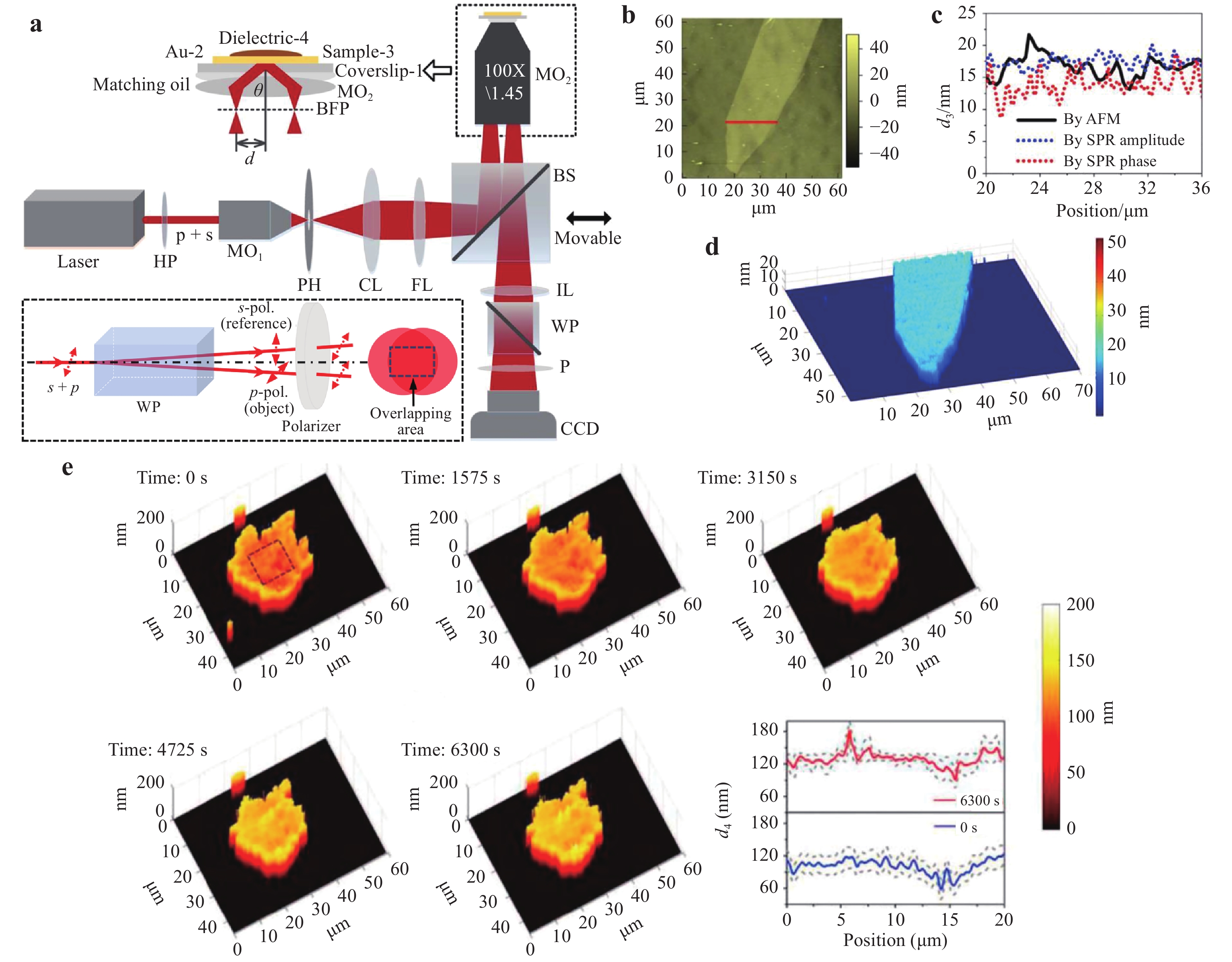
Fig. 14
a Experimental setup of common-path SPRHM based on MO-coupling configuration98. HP: half-wave plate, MO1;2: microscope objectives, PH: pinhole, CL: collimating lens, FL: focusing lens, BS: beam splitter, IL: imaging lens, WP: Wollaston prism, P: polarizer. Inset displays the principle of beam splitting using WP and the common-path recording process of the hologram. b AFM image of the test multilayer graphene film. c Thickness profile measured by AFM and SPRHM. d Teconstructed 3D thickness distribution of the film by SPRHM. e Measured adhesion gap distributions of a human breast cancer cell when t = 0, 1575, 3150, 4725, and 6300 s, during the apoptosis process by SPRHM99. Images reprinted with the following permissions: a−d98 from The Optical Society; e99 from Elsevier.The bottom inset of Fig. 14a displays the off-axis hologram-recording process. The reflected beam from MO2 is split into two orthogonally polarised components by a WP. The p-polarised component acts as the object beam carrying the SPR information of the sample. The s-polarised component acts as the reference beam carrying no sample information. The two interference beams possess the same polarisation state after passing through a polariser P and then interfere with each other. The approach of generating the uniform reference beam is different from the previously discussed common-path configurations. Compared with the lateral shearing-based type, the effective FOV of this setup is maintained without loss. Moreover, the level of common-path is greater than that of the point diffraction-based type.
Using the MO-coupling SPRHM setup in Fig. 14a, amplitude- and phase-contrast SPR images with high spatial resolution can be simultaneously obtained, by which the thin film thickness and refractive index distributions can be mapped unambiguously. Moreover, owing to the high temporal stability, this common-path SPRHM setup can be widely applied for dynamically measuring the small variations of refractive index or thickness. For example, we have measured the thickness of multilayer graphene film located in the near field of a metal surface98. The measurement resolution can achieve sub-nanometre levels. Fig. 14b−d display the experiment results. Furthermore, we also measured the adhesion gap distributions of human breast cancer cells during the apoptosis process in a dynamic and label-free manner (Fig. 14e)99.
-
We reviewed common-path configuration designs that aim to improve the temporal stability of off-axis holographic experimental setups. The common-path models were categorised into lateral shearing, point diffraction and other types. For each type, the design principle was given and the related techniques were summarised. For the lateral shearing-based type, the beam carrying the object information is first doubled using a glass plate, grating, or BS. Then, the portions of the two beams with and without the sample information create the shearing interference. This type has a simpler and more compact design compared with that of other types. However, it requires an undisturbed portion of the illumination beam to generate the reference beam, which could reduce the FOV. Moreover, it has the potential problem of a duplicated image appearing on the camera target. This type is typically applied to spatially sparse samples. Conversely, the point diffraction-based type creates a uniform reference beam from the object beam by low-pass filtering in the Fourier domain. This type does not have the problems of duplicated image and limited FOV. However, it typically has a complex configuration and the two beams are separated at the spatial filtering position, resulting in a low level of common-path. This type is suitable for measuring small samples with high spatial frequency, as it is easy to generate the uniform reference beam by spatial filtering. Finally, other advanced designs such as using folding mirrors, specially positioned BS cubes, and WPs were introduced. These designs could avoid the disadvantages existing in the former two types. For clarification, we summarise the advantages and disadvantages of the three types of common-path configurations in Table 1.
Type Advantages Disadvantages Applications Lateral shearing ■ Simple & compact configuration ■ Limited FOV
■ Duplicated image (potential)■ Spatially sparse samples Point diffraction ■ Large FOV ■ Complex configuration
■ Low level of common-path■ Small samples with high spatial frequency Others Specific design dependent Table 1. Comparison of three types of common-path configurations
The critical point for each type is to allow the object and reference beams to propagate along the same or similar optical paths. The greater the level of similarity, the better the temporal stability the setup can possess. It is worth noting that each design has its own characteristics based on the properties of the measured sample and application environment. The majority of the current common-path designs are limited to a small number of application scenarios. Therefore, boosting the applications of common-path off-axis holographic configurations is an important research direction for the future. Moreover, combining this with other imaging techniques and achieving more functionality by common-path digital holography will attract tremendous interest from different fields.
Furthermore, the reviewed common-path configurations typically include fewer optical components than traditional interferometers. Therefore, the common-path configuration is the best choice in manufacturing compact and highly stable off-axis holographic instruments. From the viewpoint of instrument investigation, it is better to design common-path interference modules that can be easily integrated with commercial setups. In this manner, significant cost and time could be saved in developing commercial instruments. The instrumentation of common-path digital holography will lead to new interdisciplinary research directions in the fields of optical, electronic, and mechanical engineering. Owing to the high stability of the common-path holographic instruments, they can be used out of the laboratories and should find wide applications in industry, chemical, biomedicine, and other fields.
-
Support from the National Natural Science Foundation of China (NSFC) (61927810, 62075183, 62005219) and Fundamental Research Funds for the Central Universities (310202011qd004) is acknowledged.
A review of common-path off-axis digital holography: towards high stable optical instrument manufacturing
-
Jiwei Zhang,
 ,
, - Siqing Dai,
- Chaojie Ma,
- Teli Xi,
-
Jianglei Di*, ,
,
-
Jianlin Zhao*, ,
- Light: Advanced Manufacturing 2, Article number: (2021)
- Received: 08 March 2021
- Revised: 10 August 2021
- Accepted: 12 August 2021 Published online: 15 September 2021
doi: https://doi.org/10.37188/lam.2021.023
Abstract: Digital holography possesses the advantages of wide-field, non-contact, precise, and dynamic measurements for the complex amplitude of object waves. Today, digital holography and its derivatives have been widely applied in interferometric measurements, three-dimensional imaging, and quantitative phase imaging, demonstrating significant potential in the material science, industry, and biomedical fields, among others. However, in conventional off-axis holographic experimental setups, the object and reference beams propagate in separated paths, resulting in low temporal stability and measurement sensitivity. By designing common-path configurations where the two interference beams share the same or similar paths, environmental disturbance to the two beams can be effectively compensated. Therefore, the temporal stability of the experimental setups for hologram recording can be significantly improved for time-lapsing measurements. In this review, we categorise the common-path models as lateral shearing, point diffraction, and other types based on the different approaches to generate the reference beam. Benefiting from compact features, common-path digital holography is extremely promising for the manufacture of highly stable optical measurement and imaging instruments in the future.
Research Summary
Common-path off-axis digital holography
Digital holography has been widely applied in the fields of interferometric measurements, three-dimensional imaging, and quantitative phase imaging. However, conventional off-axis holographic setups cannot meet the needs of advanced manufacturing due to the low temporal stability. To address this problem, common-path configurations where the object and reference beams share the same or similar optical paths, can effectively compensate environmental disturbances to the two beams. Thus, the temporal stability of the setups can be significantly improved for time-lapsing measurements. Jiwei Zhang from China’s Northwestern Polytechnical University and colleagues categorised the common-path models of off-axis digital holography into lateral shearing, point diffraction and other types, and reviewed the progress of this topic in detail. Benefiting from compact features, common-path digital holography is very promising for the manufacture of highly-stable optical measurement and imaging instruments in the future.


Rights and permissions
Open Access This article is licensed under a Creative Commons Attribution 4.0 International License, which permits use, sharing, adaptation, distribution and reproduction in any medium or format, as long as you give appropriate credit to the original author(s) and the source, provide a link to the Creative Commons license, and indicate if changes were made. The images or other third party material in this article are included in the article′s Creative Commons license, unless indicated otherwise in a credit line to the material. If material is not included in the article′s Creative Commons license and your intended use is not permitted by statutory regulation or exceeds the permitted use, you will need to obtain permission directly from the copyright holder. To view a copy of this license, visit http://creativecommons.org/licenses/by/4.0/.

 DownLoad: