


-
In recent times, the product development process using augmented reality (AR) and virtual reality (VR) has been actively advanced1. However, to enhance the realistic and immersive sensation in displays, a natural three-dimensional (3D) representation is inevitable2−4. Holographic 3D displays are suitable for this purpose because they can artificially reproduce wavefronts that are physically compatible with real 3D objects5, 6. Thus, no conflict arises between accommodation and convergence responses, which means that they can display natural 3D objects with less eye fatigue than conventional 3D displays. Moreover, both binocular parallax and continuous motion parallax can be obtained in principle. Recently, some research groups have successfully performed high-quality holographic 3D reconstructions7−9. A major factor of these methods is the extremely large number of pixels of computer-generated holograms (CGHs). However, because these CGHs were fabricated via laser lithography, animated 3D movies were not feasible. In this regard, different approach using a high-speed spatial light modulator (SLM) was proposed10. This method is based on the time-division method, where the patterns displayed on the SLM are synchronised with a scanning mirror, such as a galvano mirror. Despite the limited number of pixels of the SLM, the time-division synchronisation enabled the display performance to be equivalent to that of the CGHs with an extremely large number of pixels. Thus, this method has the potential to realise animated 3D movies if the CGHs can be calculated and transferred in real-time.
However, in the aforementioned methods, the shape of the holograms is planar, which results in a fundamental limitation in the enlargement of the viewing zone. As shown in Fig. 1a, a whole 3D object is observable only by the viewers in front of the hologram. For viewers looking at the hologram from an angle, the field of view (FOV) is limited depending on the angle from the normal to the hologram. Furthermore, no view is possible when observing from the side, top, bottom, or backward directions. This limitation stems from the shape of the hologram and is unavoidable in conventional planar holograms.
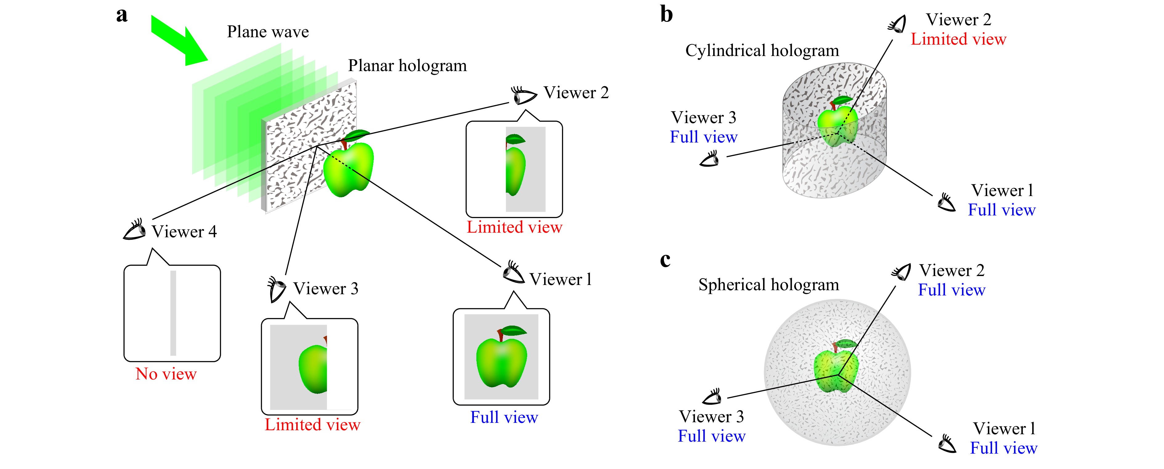
Fig. 1 Illustration of viewing zone in a a planar hologram, b cylindrical hologram and c spherical hologram.
A straightforward approach to overcome this limitation is by producing curved holograms. For example, cylindrical holograms have been proposed to enlarge the horizontal viewing zone to 360°11, 12, as shown in Fig. 1b. Computer-generated cylindrical holograms were also demonstrated13, 14. Although these methods could produce sufficient motion parallax in the horizontal direction, the vertical viewing zone was never improved and remained the same as that of the conventional planar holograms. To realise an omnidirectional observation, only the concept and calculation method for spherical holograms, as shown in Fig. 1c, were proposed15−17. However, non-planar SLMs are not currently available; however, SLMs that can dynamically change the pattern of the CGHs are necessary to display animated 3D movies. Thus, neither the cylindrical nor spherical holograms are practical solutions to overcome the limitations of planar holograms.
Our research group addressed this problem and proposed the use of a convex parabolic mirror18. As shown in Fig. 2, the convex parabolic mirror is placed between the CGH and viewers. If the CGH is designed appropriately19, the 3D object is reconstructed inside the convex parabolic mirror as a virtual image. Because the convex parabolic mirror reflects the incident wavefront radially with a wide-spread angle, the viewing zone can be enlarged in both the horizontal (azimuthal) and vertical (elevation) directions. In our previous study, azimuthal and elevation viewing zones of 150° and
$ 60^\circ $ , respectively, were experimentally demonstrated. This viewing zone is much larger than that of other preceding viewing zone enlargement methods10, 20, 21. Moreover, our previously reported method has a high potential to realise animated 3D movies while keeping the viewing zone large because only planar holograms were used and can equally be replaced by SLMs.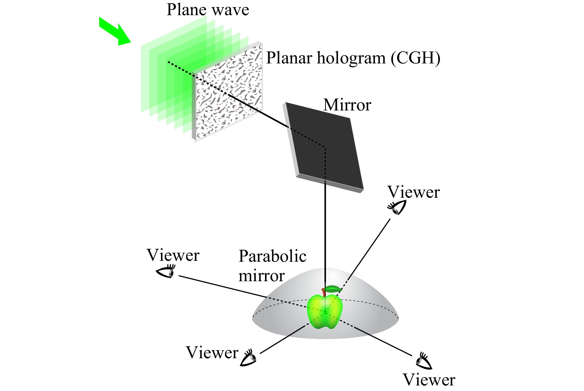
Fig. 2 Concept of our previous optical system with a convex parabolic mirror.
However, the use of a metallic convex parabolic mirror narrows its scope of applications. In particular, it is impossible to place real 3D objects inside a parabolic mirror and observe them from the outside. Thus, the superimposition of virtual 3D objects with real 3D objects, that is, AR representation, is not feasible. Moreover, the effect of interactive-physical activities, such as manipulating a virtual object with the human hand, is lost. In this study, a method to realise an AR representation is proposed using a conical holographic optical element (HOE) instead of a metallic parabolic mirror. By recording the HOE as a volume hologram, narrow-band wavelength selectivity appears. This is the see-through optical property and is indispensable for realising a holographic AR display22, 23. In this study, a conical HOE is fabricated to convert an incident plane wave into a diverging spherical wave. A 3D object is reconstructed inside the conical HOE as a virtual image. Owing to the see-through optical property, a holographic AR display with a real 3D object is demonstrated, and the viewing zone can also be enlarged in the same manner as the convex parabolic mirror.
-
Our proposed method is based on the reflection on a conical HOE. Thus, its optical property is very important. As shown in Fig. 3, our conical HOE converts the incident plane wave entering vertically downward into a spherical wave diverging outside. The maximum diverging angle
$ \omega $ is determined by an objective lens used in recording the HOE. In this study, an objective lens with a numerical aperture (NA) of 0.85 was used, and the maximum diverging angle was estimated to be approximately 58°. The wavelength used for the HOE recording was 532 nm. The apex angle was 90°, and the distance$ d $ between the apex and the divergence point O of a spherical wave, which was the origin of the conical HOE, was set to 20 mm.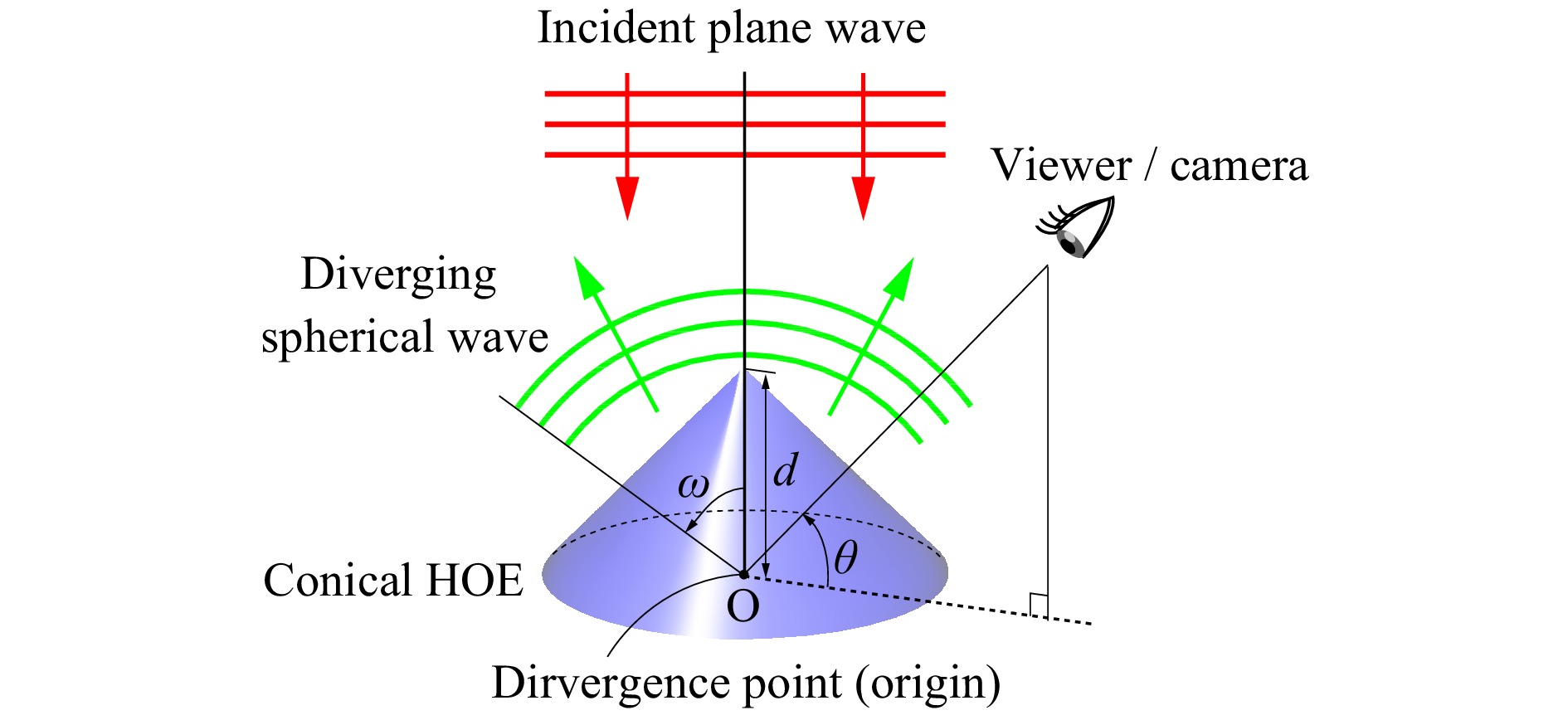
Fig. 3 Optical behaviour of a conical HOE. The incident wavefront and outgoing wavefront are depicted in red and green, respectively.
First, the generation of spherical waves by the conical HOE was investigated. As shown in Fig. 4a, a picture of the conical HOE in generating a spherical wave was captured by a digital camera. In this figure, a plane wave enters the conical HOE vertically downward, although it is invisible, and a bright spot appears inside as a virtual image. Fig. 4b shows a cross-section profile of the bright spot. This profile was obtained by capturing a bright spot using a camera with a telecentric lens and extracting a lateral line passing through the bright spot. This bright spot was a divergence point of the spherical waves, and the focus of the camera was set to this point. Thus, the full width at half maximum (FWHM) of the bright spot can be used as an evaluation index of the quality of the generated spherical waves. Because the FWHM can depend on the elevation angle
$ \theta $ , which is the angle from the horizon to the optical axis of the digital camera, the relationship between the FWHM and$ \theta $ was examined, as shown in Fig. 4c. The vicinity of the apex was distorted in forming a conical shape, although a small hole with a diameter of 5 mm was created to relieve this shape distortion. Thus, in$ \theta $ = 70° and 80°, the FWHM is slightly larger than that at other elevation angles, and the maximum elevation angle is limited to approximately$ \theta $ = 80°. If$ \theta $ is less than 40°, a bright spot does not occur, that is, no spherical wave is generated, which is valid considering the maximum diverging angle$ \omega $ .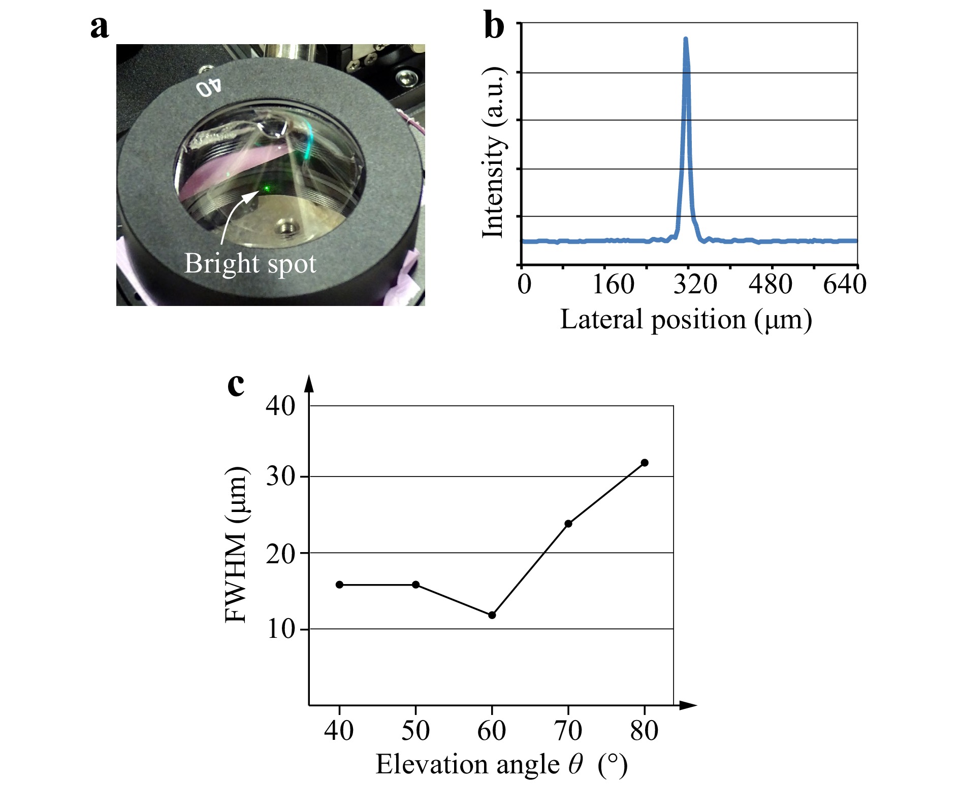
Fig. 4 Generation of diverging spherical waves. a Photograph of a conical HOE, b cross-section profile and c dependency of full width at half maximum (FWHM) on the elevation angle
$ \theta $ .Next, the diffraction efficiency of the recorded HOE was measured. In this measurement, a light wave from a laser light source with a wavelength of 532 nm entered the conical HOE directly without passing through a collimator. Thus, the illuminated area on the conical HOE was as small as the diameter of the laser light source and it was approximately 1.2 mm. An optical power meter (3664, manufacture by HIOKI E.E. Corporation) was used to measure light intensity diffracted from the conical HOE. Fig. 5 shows the diffraction efficiency versus the elevation angle
$ \theta $ . The diffraction efficiency was defined as the ratio of the diffracted light intensity to the input light intensity. The diffraction efficiency had the strong dependency on the elevation angle$ \theta $ , and its peak appeared at$ \theta $ = 60°. On the other hand, the diffraction efficiency in$ \theta $ = 80° was significantly low. This needs to be improved by optimizing experimental conditions.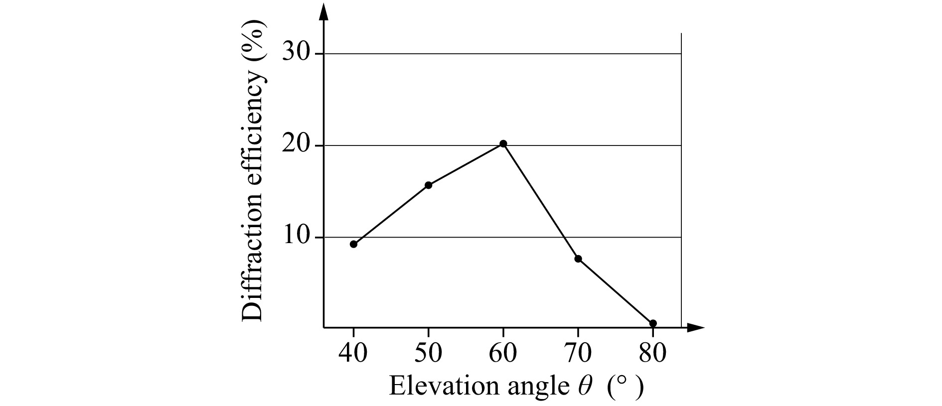
Fig. 5 Diffraction efficiency of a conical HOE.
Then, the wavelength selectivity of the conical HOE was also examined. White light emitted from an LED light source was shaped into a quasi-plane wave when passing through a lens. This quasi-plane wave entered the conical HOE parallel to its rotationally symmetric axis. A spectrometer (QEPro, manufactured by Ocean Optics) picked up the light reflected on the conical HOE. For example, in the case of
$ \theta \cong $ 60°, the spectral reflectivity is shown in Fig. 6. This spectral reflectivity was calculated by dividing the spectral intensity obtained using the spectrometer by the spectrum of the incident light and normalizing it based on a maximum value. Fig. 6 shows the sharp peak near the wavelength of 532 nm, which corresponds to the wavelength used in recording the conical HOE. The FWHM of this sharp peak is approximately 11 nm. The spectral bandwidth of 11 nm is considered to be proper in this study because a light wave with this bandwidth can be treated substantially as a monochromatic light. In addition, moderate bandwidth is necessary to relax incident light conditions in reconstruction. Thus, this wavelength selectivity is indispensable for realising our holographic AR display.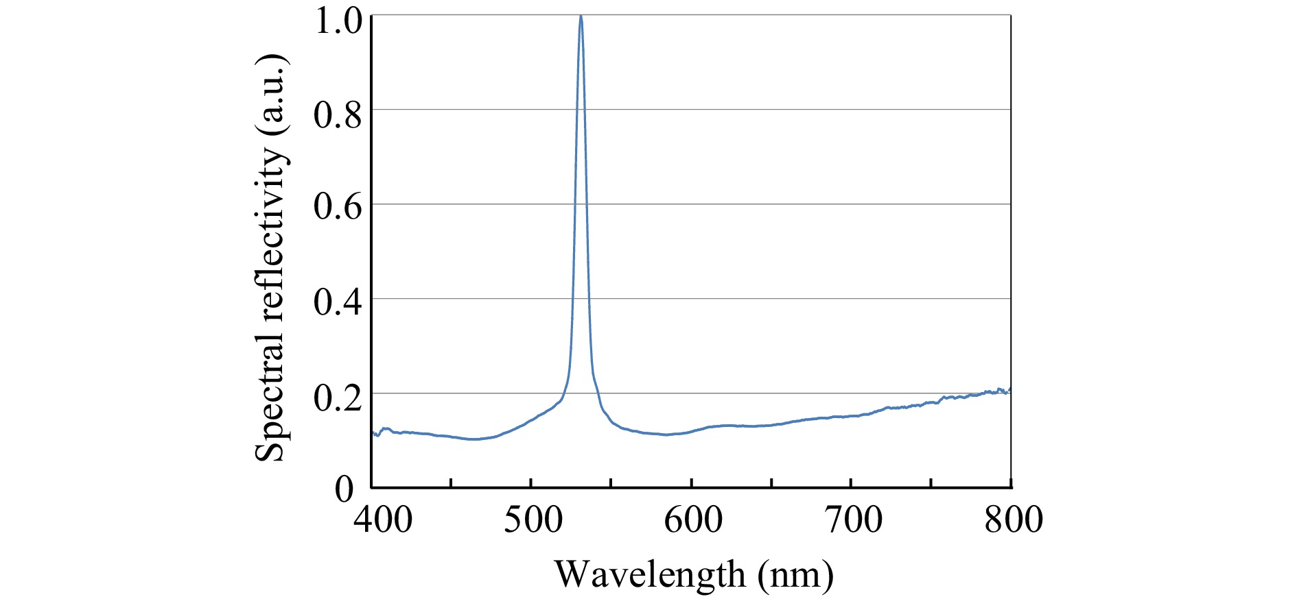
Fig. 6 Wavelength selectivity of a conical HOE.
-
A holographic AR display system with a very large viewing zone was constructed. A schematic of the optical system with a conical HOE is shown in Fig. 7. A fiber-output laser with a wavelength of 532 nm was used as the light source. After passing through lens L
$ _1 $ , the collimated wave enters the CGH as a plane wave. Then, the wavefront modulated by the CGH was optically Fourier-transformed by lens L$ _2 $ with a focal length$ f $ of 150 mm. On the Fourier plane of lens L$ _2 $ , a spatial filter was inserted and half of the wavefront was filtered to remove unwanted waves such as the 0th-order and conjugated waves because the CGH in this study is a binary-amplitude type. The filtered wavefront entered the conical HOE vertically downward, was reflected in very wide directions, and then arrived at the viewers. If the CGH pattern is designed properly by considering the reflection on the conical HOE, then the viewers can recognise a reconstructed 3D object inside the conical HOE as a virtual image.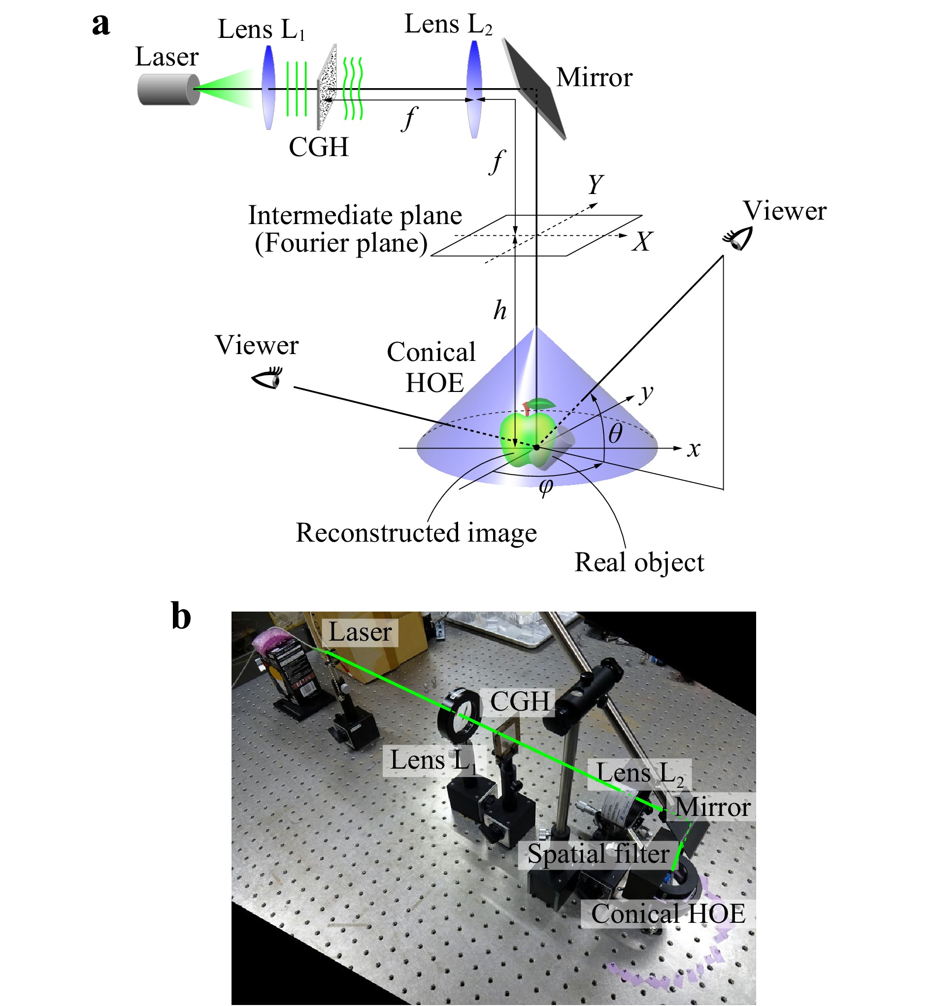
Fig. 7 a Schematic and b a picture of our holographic AR display system constructed.
In this study, a wire-frame cube was used as a virtual 3D object, as shown in Fig. 8a. Four line segments were added at the four corners of the frontal face to distinguish it from the back face. The size of the wire-frame cube was 1.32 mm × 1.32 mm × 1.32 mm. The number of pixels and pixel pitch of the CGH were 8,192 × 8,192 and 3.5 µm × 3.5 µm, respectively. The number of the point light sources constituting the 3D object was 420. The total calculation time was approximately 12.5 hours. The binary-amplitude pattern of the CGH was formed on a glass substrate by direct laser writing and wet etching. The distance
$ h $ between the back Fourier plane of lens L$ _2 $ and the origin of the conical HOE was set to 25 mm. The real object, which was superimposed with the virtual 3D object in the optical reconstruction, was a metallic screw, as shown in Fig. 8b, and it was located by the virtual 3D object.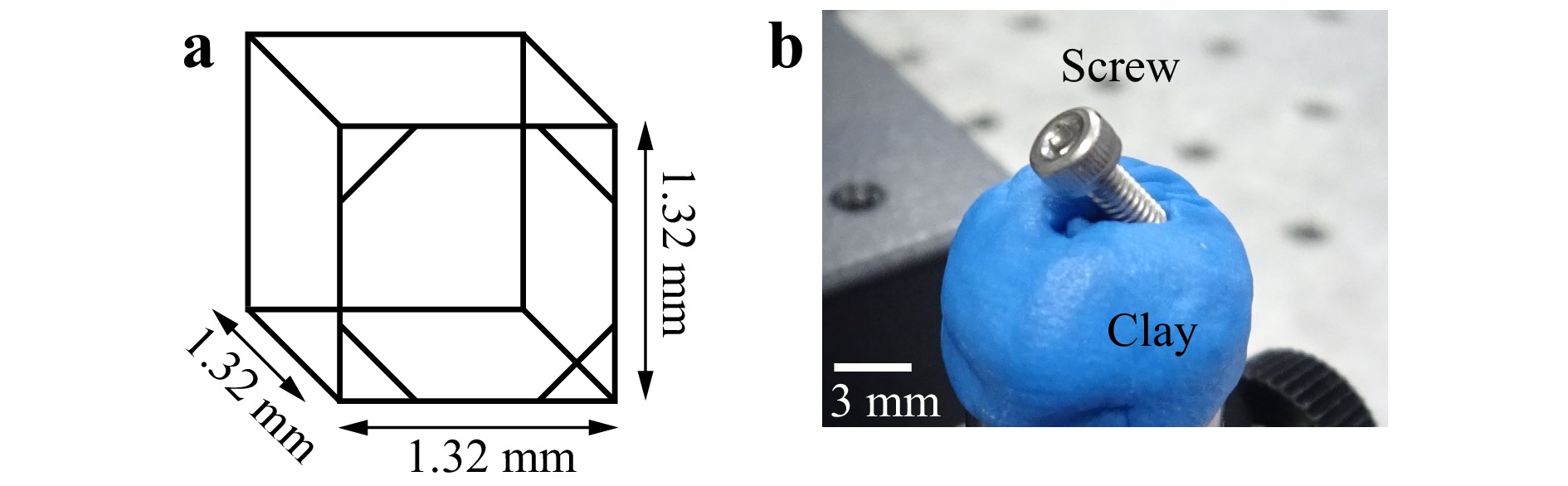
Fig. 8 A 3D object used for the demonstration. a Schematic of the virtual 3D object and b picture of the real object.
Under these conditions, the optical reconstruction of the virtual 3D object with the real object was demonstrated. Some images captured from various directions are shown in Fig. 9. In the experiment, the rotation angle of the conical HOE was adjusted per photograph to avoid using the unavailable areas of the conical HOE because some flaked parts between the photopolymer film and the conical plastic mould were found. Moreover, the shape of the mould, especially in the vicinity of the apex, was never geometrically correct. However, this treatment is not as significant to verify the validity of our proposed method because the conical HOE is rotationally symmetric. In Fig. 9, the horizontal and vertical positions of each image indicate the azimuthal
$ \varphi $ and elevation$ \theta $ angles, respectively, as is shown in Fig. 7a. Because the wire-frame cube is reconstructed as a virtual image, its image is properly reconstructed without disturbance by the real object; therefore, an AR reconstruction is realised. As shown in this figure, the reconstructed images change appropriately as the viewing direction change. Thus, the realisation of motion parallax and 3D reconstruction are successfully demonstrated. Concerning the viewing zone, our proposed method can present a very wide viewing zone, as well as our previous method using a convex parabolic mirror18, 19. The azimuthal range of 150° and elevation range of 30° are experimentally confirmed. In Fig. 9, there is no image at the upper right or upper left. Even in these directions, the 3D object could be reconstructed in the same way as the other viewing directions, although these reconstructed images could not be photographed because of the physical contact of the digital camera with a mirror, as shown in Fig. 7.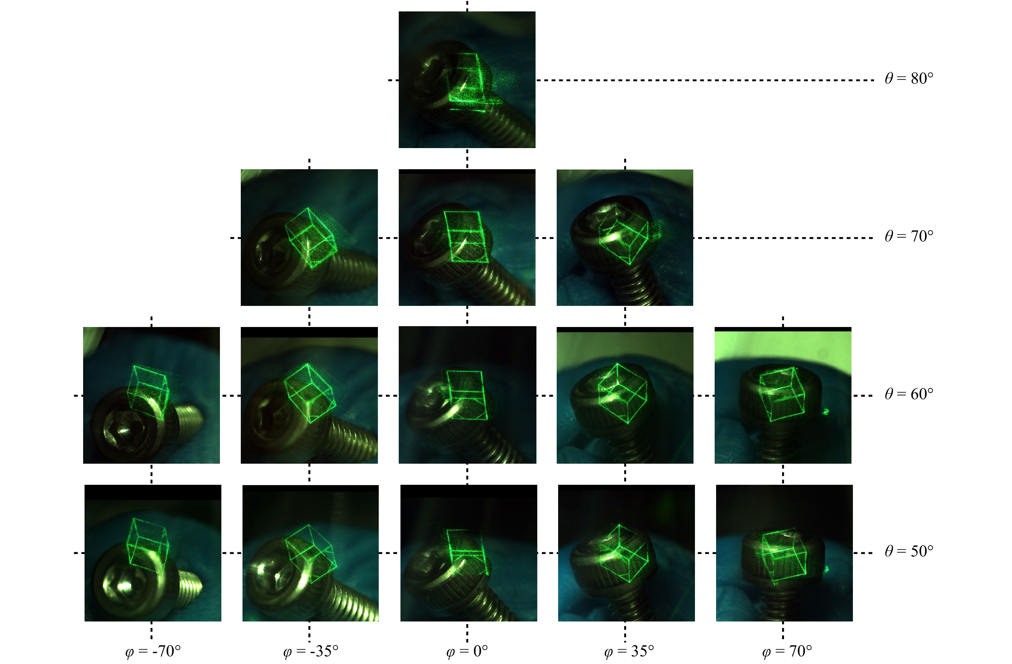
Fig. 9 Photographs of AR representation of holographically reconstructed images with a real object of a metallic screw. Each image was captured from the direction indicated by
$ \theta $ and$ \varphi $ .As can be seen from Fig. 9, the reconstructed 3D objects are distorted. The degree of the distortion varies with reconstruction positions and observation directions. This distortion stems from the misalignment of the optical system, especially the optical property of the conical HOE. The deviation from ideal conical shape results in the distortion of the reconstructed images. This distortion should be evaluated and modified for further development. Moreover, the reconstructible object space is important in holographic 3D displays. The reconstructible object space is not a cuboid or a cone, and it is very difficult to theoretically derive and determine that space because conventional diffraction theory is based on paraxial approximation and can not be applied to a conical HOE with a very wide spread-angle used in this study. Thus, by analysing a spatial-frequency bandwidth of the generated CGH, the reconstructible object size was numerically estimated to be roughly 2 mm. Further analysis will be required to evaluate our proposed method correctly.
-
Notably, the main advantage of our proposed method using a conical HOE is the wide viewing zone. However, the maximum angle of the viewing zone was limited by some factors. One of these was the maximum diverging angle
$ \omega $ of the objective lens, as shown in Fig. 3. Because the conical HOE was recorded using a spherical wave as an object wave, the maximum angle of the vertical viewing zone was limited by$ \omega $ . The other factor was the illumination area of the incident wavefronts to the conical HOE. To widen the viewing zone, the outer area of the conical HOE needs to be illuminated. Thus, the lateral size of the incident wavefront also determines the viewing zone because the size of it is smaller than that of the conical HOE in this study. In our optical system shown in Fig. 7a, to enlarge the lateral size, it is necessary to reduce the pixel pitch of the CGH or to use a lens with a large focal length. However, in the same way as the conventional holographic 3D display, there is a trade-off relation between the object size and the viewing zone. For example, if a lens with a longer focal length enlarges the viewing zone, the reconstructible object size reduces, and vice versa. Thus, increasing the number of pixels of CGHs is necessary to realise large object reconstructions and wide viewing zones simultaneously. On this point, our proposed method is advantageous because the shape of the hologram is planar. In the case of planar holograms, it is possible to increase the total number of the CGH or SLM pixels via the spatial tiling of multiple SLMs24, 25. If these methods are incorporated into our holographic 3D display, both large object reconstructions and wide viewing zones can be realised.In contrast, the azimuthal viewing zone
$ \varphi $ is, in principle, 360° because the conical HOE is rotationally symmetric. However, it was less than 180° in our optical demonstration. This is because a spatial filter is inserted, as shown in Fig. 7b, and only the half area of the conical HOE was illuminated. Thus, if a complex-modulation encoding method is used instead of a simple binary-amplitude hologram26−28, inserting a spatial filter is no longer necessary, and the azimuthal viewing zone becomes 360°. -
A conical HOE is a holographic optical element. A transparent conical-shaped mould was formed by bending a fan-shaped acrylic plastic under an atmosphere temperature of 120 °C and sticking it. A photopolymer film (Bayhol HX200, manufactured by Covestro AG) was used as a photosensitive material, and it adhered closely to the top side of the conical-shaped mould. The thickness of the conical-shaped mould was 1 mm. This thickness was selected by considering both the effect on the wavefront passing through it and the deformation of the conical-shaped mould in recording. The optical properties of an HOE are determined by an optical system recording holographic interference fringes. Fig. 10 shows the schematic of the optical system to record a conical HOE in this study. A wavefront emitted from a laser light source was collimated by lens L
$ _1 $ , and then split into two plane waves by a beam splitter. One was used as the reference wave. The other became a diverging spherical wave by passing through an objective lens. These two waves interfered each other, and resultant interference fringes were recorded in the photopolymer film. The exposure time was set to 50 s, and the irradiance of the reference wave was 1.0 mW/cm2. Because the propagation directions of these two waves were opposite, their interference fringes form 3D structure in the photopolymer film on the conical-shaped mould. The hologram recorded in this setup was called a volume-type hologram and had a sharp wavelength selectively. After bleaching the recorded photopolymer film with white light, the conical HOE was completed. In the reconstruction process, the conical HOE behaved as a reflective curved mirror whose focal length was$ d $ and NA was 0.85, as shown in Fig. 3. When the conical HOE was illuminated with an incident wave propagating parallel to its rotationally symmetric axis, the diverging spherical wave was reconstructed after the diffractive reflection on the conical HOE.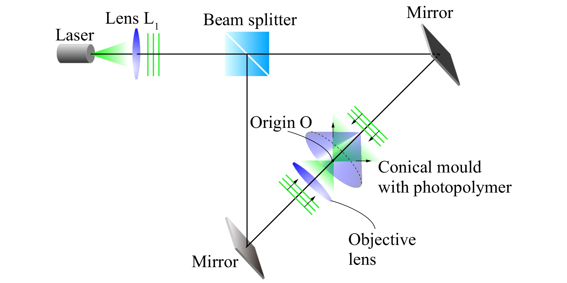
Fig. 10 Schematic of the optical system to record a conical HOE.
-
In our proposed method, a 3D object is reconstructed inside the conical HOE after reflection. Thus, the pattern of the CGH must be properly designed by considering the reflection on the conical HOE. Although various diffraction calculation methods including Fresnel diffraction have been proposed, they can be applied only to planar surfaces. In this study, the calculation method was originally developed based on geometrical optics by modifying the calculation method reported in our previous study18. Our calculation method presents the diffraction from a virtual 3D object to the intermediate plane located over the conical HOE, as shown in Fig. 7a. This intermediate plane is
$ h $ = 25 mm away from the origin of the conical HOE and is placed such that it becomes the Fourier plane of lens L$ _2 $ .First, the virtual 3D object is assumed to be an aggregation of point light sources emitting spherical waves isotropically. The optical path from a single point light source S of the 3D object to a sampling point M on the intermediate plane through the reflection on the conical HOE is considered herein. A schematic of the configuration of the calculation method is shown in Fig. 11, where the origin O of the conical HOE is set at the divergence point of the spherical wave. The optical path is divided into two parts. The first is from S to the reflection point R on the conical surface. The second is from the reflection point R to M. Because the 3D object is reconstructed inside the conical HOE as a virtual image, the first part diffraction is in the forward direction, whereas the second part diffraction is in the backward direction. Thus, the optical path length from S to M is obtained as the difference between these two path lengths. Moreover, to obtain the optical path length, it is necessary to precisely determine the spatial position of the reflection point R on the conical HOE. When the spatial coordinates of the three points S, R, and M are introduced as
$ (x_S, y_S, z_S) $ ,$ (x_R, y_R, z_R) $ , and$ (x_M, y_M, z_M) $ , respectively, the optical path length$ l $ from S to M is expressed by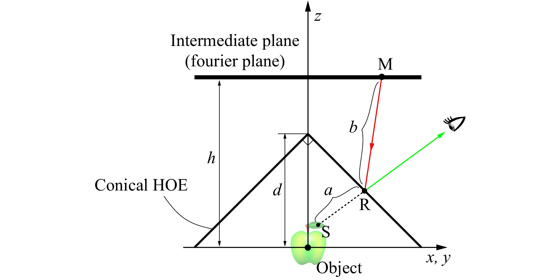
Fig. 11 Schematic of the conical HOE reflection for the CGH calculation.
$$ l(x_R, y_R, z_R) =a(x_R, y_R, z_R) - b(x_R, y_R, z_R) + \phi(x_R, y_R, z_R) $$ (1) where
$ a $ and$ b $ represent the optical path lengths of the first and second part diffractions, respectively, and they are given by$$ \begin{align} a &= \sqrt{(x_R-x_S)^2 + (y_R-y_S)^2 + (z_R-z_S)^2} \end{align} $$ (2) $$ \begin{align} b &= \sqrt{(x_M-x_R)^2 + (y_M-y_R)^2 + (z_M-z_R)^2} \end{align} $$ (3) $ \phi $ corresponds to the phase retardation as a result of reflecting on the conical HOE. Because this phase retardation stems from the optical path difference between a reference wave and an object wave in recording the conical HOE,$ \phi $ is formulated as$$ \begin{align} \phi(x_R, y_R, z_R) = (h-z_R) - \sqrt{x_R^2 + y_R^2 + z_R^2} \end{align} $$ (4) The first and second terms represent the optical path lengths of the reference and object waves, respectively. According to Fermat’s principle, the light ray traces the shortest optical path29, which means that the spatial position
$ (x_R, y_R, z_R) $ of point R is obtained as the solution which minimises the optical path length$ l $ . Note that the reflection point R is constrained on the conical surface as follows:$$ \begin{align} z_R = d - \sqrt{x_R^2 + y_R^2} \end{align} $$ (5) where
$ d $ is the distance from the origin O to the apex of the conical HOE, as shown in Fig. 11. The spatial position$ (x_R, y_R, z_R) $ is obtained by solving the minimisation problem with this constraint. In this study, this minimisation problem was solved using the Lagrange multiplier method30. The Lagrange function$ \mathcal{L}(x_R, y_R, z_R, \lambda) $ is defined by$$ \begin{align} \mathcal{L}(x_R, y_R, z_R, \lambda) = l(x_R, y_R, z_R) - \lambda g(x_R, y_R, z_R) \end{align} $$ (6) where
$ \lambda $ is a Lagrange multiplier and$ g(x_R, y_R, z_R) $ is$$ \begin{align} g(x_R, y_R, z_R) = z_R - d + \sqrt{x_R^2 + y_R^2} \end{align} $$ (7) Because the solution of
$ (x_R, y_R, z_R) $ minimises$ l(x_R, y_R, z_R) $ , the following equations should be satisfied:$$ \begin{align} &\frac{\partial \mathcal{L}}{\partial x_R} = \frac{x_R - x_S}{a} + \frac{x_M - x_R}{b} - \frac{x_R}{s} - \frac{\lambda x_R}{r} = 0 \end{align} $$ (8) $$ \begin{align} &\frac{\partial \mathcal{L}}{\partial y_R} = \frac{y_R - y_S}{a} + \frac{y_M - y_R}{b} - \frac{y_R}{s} - \frac{\lambda y_R}{r} = 0 \end{align} $$ (9) $$ \begin{align} &\frac{\partial \mathcal{L}}{\partial z_R} = \frac{z_R - z_S}{a} + \frac{z_M - z_R}{b} - \frac{z_R}{s} -1 -\lambda = 0 \end{align} $$ (10) $$ \begin{align} &\frac{\partial \mathcal{L}}{\partial \lambda} = -g(x_R, y_R, z_R) = -z_R + d - r = 0 \end{align} $$ (11) where
$$ \begin{align} s &= \sqrt{x_R^2+y_R^2+z_R^2} \end{align} $$ (12) $$ \begin{align} r &= \sqrt{x_R^2+y_R^2} \end{align} $$ (13) As can be seen from Eqs. 10, 11, both
$ z_R $ and$ \lambda $ can be rewritten as explicit functions of the variables$ x_R $ and$ y_R $ . Therefore, by substituting the explicit functions$ z_R $ and$ \lambda $ in Eqs. 8, 9, the above minimisation problem with the constraint is reduced to a nonlinear simultaneous equation with respect to two variables$ x_R $ and$ y_R $ . However, this simultaneous equation cannot be solved analytically. In this study, Newton’s method with two variables was used to numerically solve the simultaneous equation31.When the position of the reflection point R is determined, the optical path length from S to M via R can easily be calculated using Eq. 1, and the complex amplitude at point M contributed by point S is obtained. By repeating this procedure for all the point light sources constituting the 3D object and for all the sampling points on the intermediate plane, it becomes possible to calculate the complex wavefront on the intermediate plane diffracted from the 3D object to be reconstructed. Therefore, by the inverse Fourier transformation of this complex wavefront, the wavefront on the CGH plane is obtained because the intermediate plane is located at the Fourier plane of lens L
$ _2 $ , as shown in Fig. 7a. Note that the lateral half of the complex wavefront on the intermediate plane must be set to zero before the inverse Fourier transformation. Finally, the real part of the resultant wavefront on the CGH is extracted and binarized because the CGH fabricated in this study is of the binary-amplitude type. -
This research was partially supported by JSPS KAKENHI Grant Number JP20K11914.
Holographic augmented reality display with conical holographic optical element for wide viewing zone
- Light: Advanced Manufacturing 3, Article number: (2022)
- Received: 16 August 2021
- Revised: 10 February 2022
- Accepted: 15 February 2022 Published online: 02 March 2022
doi: https://doi.org/10.37188/lam.2022.012
Abstract: In this study, we propose a holographic augmented reality (AR) display with a wide viewing zone realized by using a special-designed reflective optical element. A conical holographic optical element (HOE) is used as such a reflective optical element. This conical HOE was implemented to reconstruct a diverging spherical wave with a wide spread angle. It has a sharp wavelength selectivity by recording it as a volume hologram, enabling augmented reality (AR) representation of real and virtual 3D objects. The quality of the generated spherical wave and the spectral reflectivity of the fabricated conical HOE were investigated. An optical superimposition between real and virtual 3D objects was demonstrated, thereby enhancing the validity of our proposed method. A horizontal viewing zone of 140° and a vertical viewing zone of 30° were experimentally confirmed. The fabrication procedure for the conical HOE is presented, and the calculation method of the computer-generated hologram (CGH) based on Fermat’s principle is explained in detail.
Research Summary
Surrounding viewing zone: Beyond the limitation of planar holograms
Holographic displays are expected for futuristic 3D displays. One problem to its practical application is the narrow viewing zone. No sufficient motion parallax is realized at present. One reason for the narrow viewing zone stems from the shape of holograms, and conventional planar hologram cannot provide surrounding viewing zone. This study presents a new technique to overcome this limitation. In this study, a conical holographic optical element (HOE) is placed after the hologram modulation. Because the conical HOE generates a widely diverging spherical wave, the viewing zone can be enlarged. Moreover, by using the sharp wavelength selectivity of the HOE, augmented reality (AR) representation is also feasible. The optical experiment has successfully demonstrated the wide viewing zone of 140◦ and 30◦ in the horizontal and vertical directions, respectively.


Rights and permissions
Open Access This article is licensed under a Creative Commons Attribution 4.0 International License, which permits use, sharing, adaptation, distribution and reproduction in any medium or format, as long as you give appropriate credit to the original author(s) and the source, provide a link to the Creative Commons license, and indicate if changes were made. The images or other third party material in this article are included in the article′s Creative Commons license, unless indicated otherwise in a credit line to the material. If material is not included in the article′s Creative Commons license and your intended use is not permitted by statutory regulation or exceeds the permitted use, you will need to obtain permission directly from the copyright holder. To view a copy of this license, visit http://creativecommons.org/licenses/by/4.0/.

 DownLoad: