


-
Liquid-crystal (LC) phase modulators have been widely used in adaptive optics, optical communication, and laser beam steering owing to their advantages of low power consumption, light weight, flexible bandwidth adjustment, and non-mechanical movements1-5. In optical communication applicatons6,7, the LC phase modulator serves as a spatial light modulator (SLM) in wavelength-selective switches and flexibly controls the selection of communication channels8,9. However, the use of linear polarizers for SLMs greatly limits the optical efficiency and increases the complexity of the communication systems5,10, similar to other LC phase modulation devices9,11. Therefore, the development of polarization-independent LC-phase modulators is urgently required12,13. There are two approaches to realizing polarization-independent LC phase modulators. The first is to change the LC material that constitutes the LC phase modulator14. The most common method utilizes polarization-independent polymer-stabilized blue-phase liquid crystals (PS-BPLCs)1,15-18. However, for LC phase modulators that use PS-BPLC materials, the driving voltage is generally extremely high, making them unsuitable for integration. The second is to change the alignment of the LC directors. Polarization-independent performance can be achieved for both types of LC phase modulators by changing the alignment structure of the LC. One type is the double-layer LC cell19,20, formed by the orthogonal stacking of two identical LC cells. Light incident on the device can be decomposed into two linearly polarized light beams along the orthogonal LC layers. After propagating through the two orthogonal LC layers, the linearly polarized light in both directions has the same phase-modulation depth. However, the production of double-layer devices is limited by their complex structures and preparation processes. The second type is the orthogonal photoalignment21-23. The difficulty with this method lies in the alignment process. It is difficult to achieve precise alignment of the microdomains using the conventional process of photoalignment followed by sealing.
A light-controlled azimuth angle (LCAA) process based on the optical rotatory effect of a cholesteric liquid crystal (CLC) is proposed herein for fabricating a multi-microdomain orthogonally twisted (MMOT) device. This device has a low polarization dependence with high phase retardation and a simple structure. Both the alignment angle between the top and bottom substrates in the LCAA process and the mask grid size of the MMOT structure can be specially designed to satisfy the requirements of different applications.
-
The optical rotation of the CLC is determined by the light wavelength and helical pitch24, as shown in Eq. 1.
$$ R = - \frac{{\pi {{(\Delta n)}^2}p}}{{4{\lambda _0}(1 - {{\lambda _0^2} \mathord{\left/ {\vphantom {{\lambda _0^2} {{p^2}{n^2}}}} \right. } {{p^2}{n^2}}})}} $$ (1) where R is the rotatory power of the CLC; Δn, λ0, and n are the birefringence, light wavelength, and average refractive index, respectively. P is the helical pitch of the CLC, expressed by Eq. 2.
$$ p = \frac{1}{{c \cdot HTP}} $$ (2) where c and HTP are the weight concentration of the chiral dopant and helical twist power of the chiral dopant, respectively. For the quantitative design, λ0, Δn, and n are set as 405 nm, 0.2, and 1.6, respectively.
Fig. 1 shows the relationship between the rotatory angle and the pitch for a LC of 12 μm. When the product of n and p is close to the wavelength of the light, the rotatory angle changes rapidly. Half of the light is reflected by the helical structure of the CLC via Bragg reflection. However, when the helical pitch was changed, the Bragg reflection decreased rapidly. As shown by the red square in Fig. 1, the rotatory angle maintained a large range with small changes. This figure illustrates the rotatory angle for a pitch of 350–400 nm for a LC layer with a thickness of 12 μm. For a CLC pitch of 380 nm, the polarization of 405 nm light is rotated by 90°.
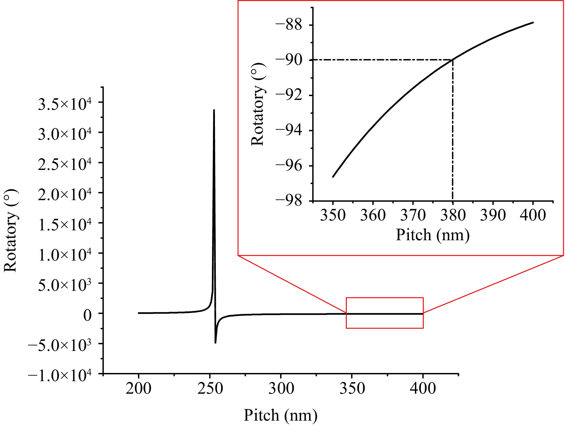
Fig. 1 Relationship between rotatory angle and pitch for LC of 12 μm.
-
Fig. 2 shows a diagrammatic of the principle of the LCAA process. After propagating through the optical rotation layer of the CLC, the linear polarization direction of the exposure source incident on the top and bottom substrates was at a certain angle. By controlling the rotation angle of the CLC, the LC molecules on the top and bottom substrates can be aligned perpendicular to each other.
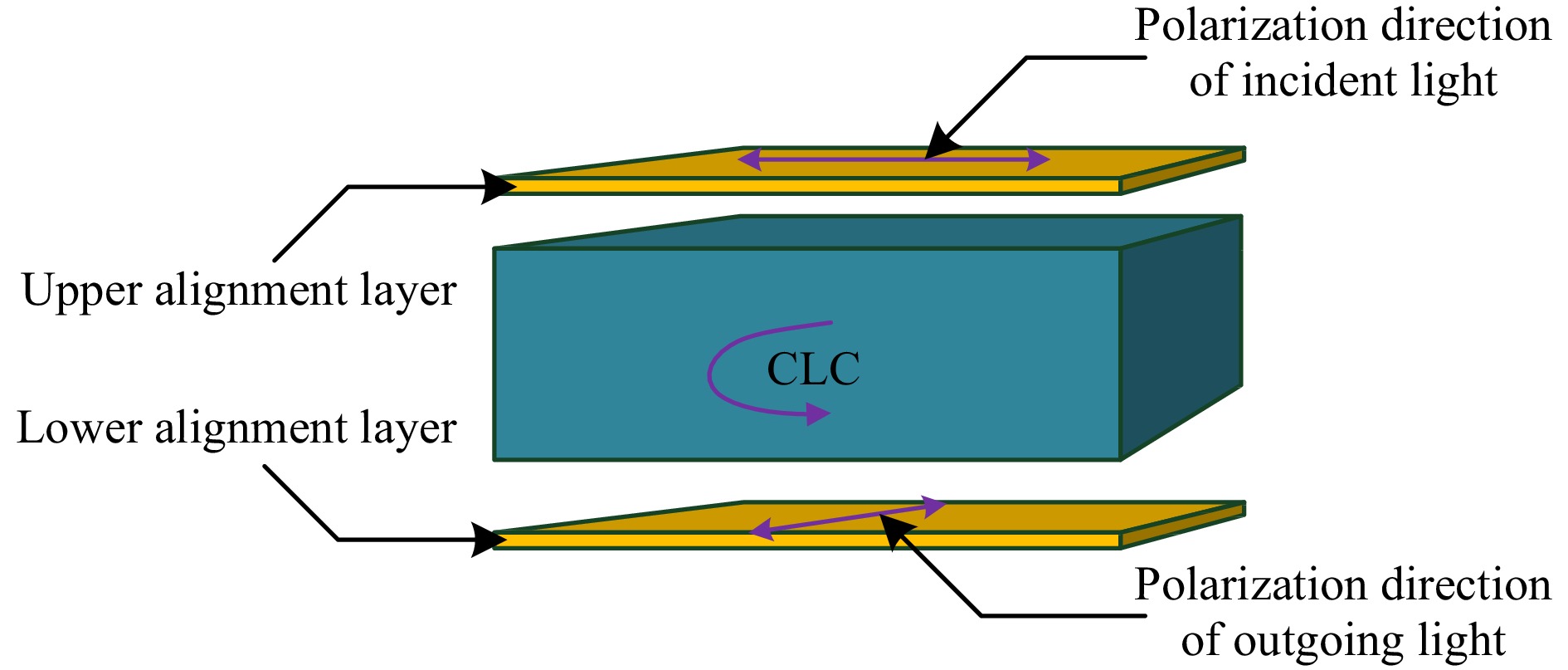
Fig. 2 Diagram showing principle of the LCAA process.
The photoalignment layer comprised an ultrasonically cleaned, ultraviolet-light-irradiated glass substrate. The azo-dye SD1 (dissolved in dimethylformamide at 0.30 wt%) was spin-coated onto a glass substrate at 500 rpm for 10 s and then at 2500 rpm for 20 s as the photoalignment layer. Finally, the substrate was heated at 200 °C for 10 min to remove the residual solvents. The detailed steps in the fabrication of the twisted-alignment LC cell using the LCAA process are as follows:
1. Pre-exposure: The LC cell with the photoalignment layers was placed under a linearly polarized UV lamp (wavelength of approximately 405 nm); the exposure dose was approximately 5 J/cm2. The SD1 molecules tend to align along the direction perpendicular to the polarization electric field. Pre-exposure allows initial alignment of the CLCs in a uniform direction.
2. Twisted alignment exposure: The empty LC cell filled with CLC (the rotation angle was approximately 90°) was placed under linearly polarized UV light; the exposure dose was approximately 8 J/cm2 (because the CLC layer reflects part of the light, the exposure dose was appropriately increased). As a rotating layer, the CLC can orient the polarization directions of the exposure light incident of the top and bottom alignment layers orthogonal to each other.
3. Leaching of CLC: After exposure, the LC cells were placed in acetone or ethanol and soaked for 24 h to leach out the CLC.
4. Refilling the nematic LC: The prepared empty LC cell was refilled with the desired nematic LC.
The optical path diagram for measuring the rotation angle of the LC cell is shown in Fig. 3a. The transmittance curves of the TN-LC cell were obtained by rotating the analyzer according to the optical path diagram. The transmission curves of the TN-LC cells prepared using the LCAA and rubbing alignment methods are shown in Fig. 3b, demonstrating that the rotation angles of the TN-LC cells prepared using the two methods were basically the same. This demonstrates precise rotation between the alignment directions of the top and bottom substrates.
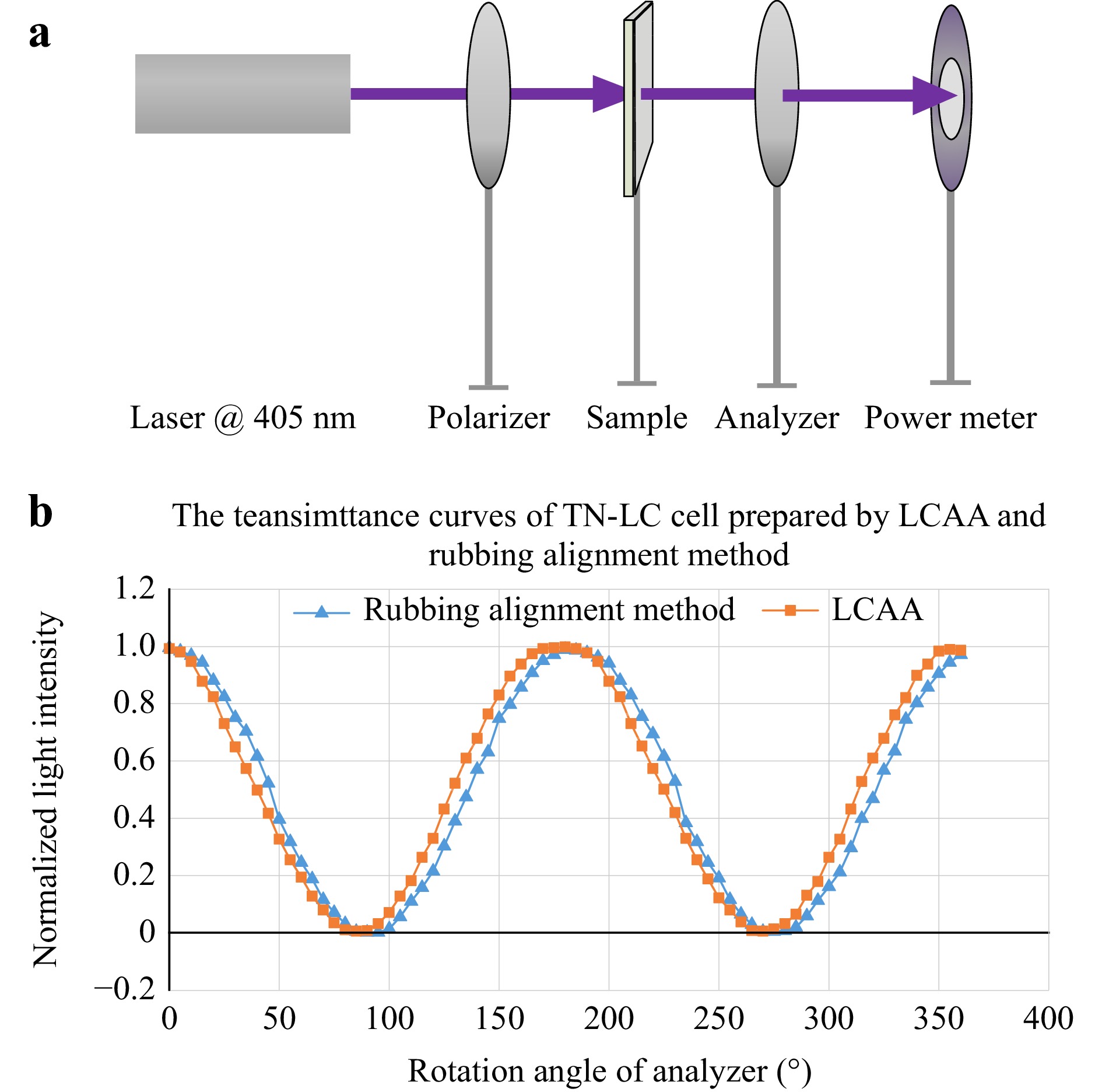
Fig. 3 a Setup for measurement of rotation angle, b transmission curves of TN-LC cell prepared by LCAA process and rubbing alignment method.
-
Using the LCAA process, a MMOT structure was proposed for achieving polarization-independent retardation. A schematic of the LC phase modulator with the MMOT structure is shown in Fig. 4a. Fig. 4b shows the arrangement of the LC molecules on the top and bottom alignment layers.
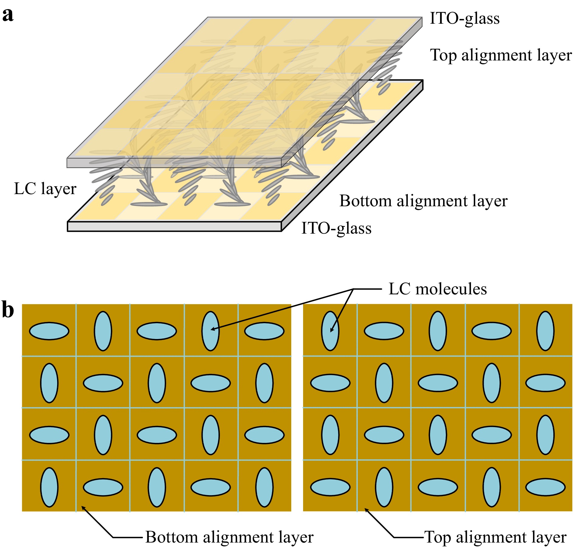
Fig. 4 a Schematic of LC phase modulator with MMOT structure, b arrangement of LC molecules on the top and bottom alignment layers.
Each alignment layer had multiple microdomains, and each microdomain had a twisted structure. For certain microdomain alignments, when a voltage is applied to the cell, the LC molecules can only modulate the polarization components in the parallel direction, whereas in the orthogonal direction, the phase retardation remains unchanged. For adjacent orthogonally oriented microdomains, the polarization components are modulated in exactly opposite directions, and the modulation is the same. Therefore, only 50% of the incident light is modulated in a polarization-independent manner with an orthogonal photoalignment structure. However, when a high voltage is applied, the TN structure exhibits certain polarization-independent modulation characteristics. At this time, the energy utilization is improved, and low-loss polarization-independent phase modulation is achieved. Fig. 5 shows the process for fabricating the LC phase modulator with the MMOT structure. The arrows under the lamps represent the polarized direction of the UV light, and the arrows on the alignment layers represent the alignment direction of the rewritten SD1 molecules. The fabrication process included three exposure steps. The first step was pre-exposure; the exposure light source was an ultraviolet light source, and the exposure dose was approximately 5 J/cm2. After the first exposure, the device exhibited an anti-parallel alignment structure, and the CLC was injected for the second exposure. During the second exposure, the polarization direction of the exposed light source was unchanged and the exposure dose was increased to approximately 8 J/cm2. After the second exposure, the device structure was twisted owing to the erasability of the photoalignment layer. A grid mask was then added between the light source and device. The polarization direction of the light source was rotated by 90° for the third exposure, and the exposure dose was increased to approximately 11 J/cm2 (because the mask reflects part of the light, the exposure dose should be increased appropriately). The device was then immersed in ethanol or acetone for 24 h to remove the CLC. Finally, the device was refilled with nematic LC.
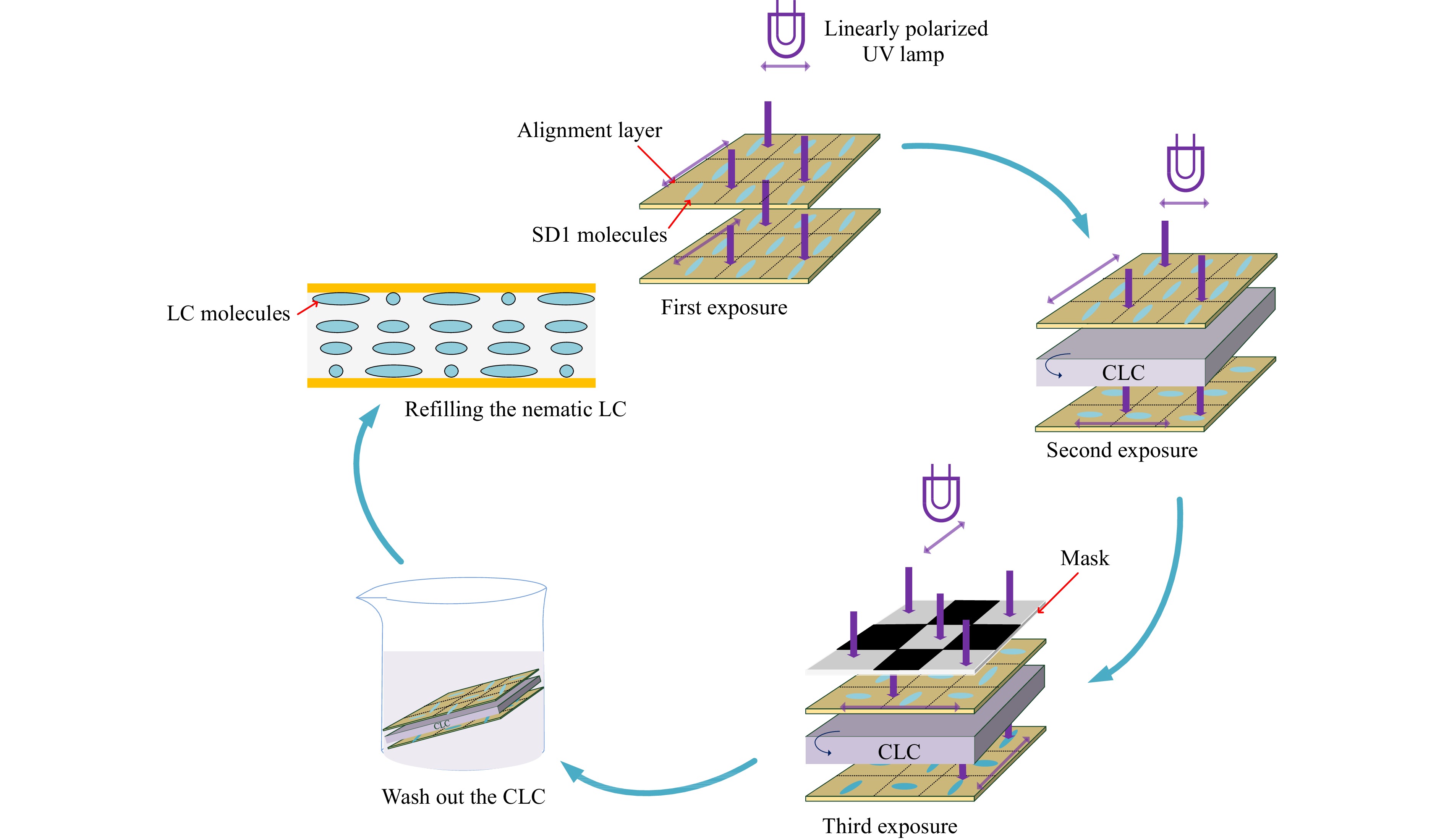
Fig. 5 Process for fabricating LC phase modulator with the MMOT structure.
-
An LC phase modulator with the MMOT structure was fabricated using a CLC mixture comprising a nematic LC (E7, 76.08 wt%) and a left-handed chiral dopant (S811, 23.92 wt%). The cell gap was 12 μm and the size of the mask grids was 0.1 mm × 0.1 mm. The sizes of the cell gap and mask grid can be specially designed to satisfy different requirements. Fig. 6a illustrates the experimental optical setup used to measure the polarization independence of the modulator. The beam from a 532 nm laser was linearly polarized with the polarizer. Using a beam splitter, the beam was then split into two parts that subsequently served as the reference beam and the object beam. The reference beam was sent through a half-wave plate to transform the polarization to 45°, and the object beam was sent through a phase modulator. The two beams were then recombined using another beam splitter. A CCD camera was placed behind the beam splitter to project interference fringes. An analyzer was placed in front of the camera to enhance the contrast of the interference fringes. When a voltage was applied to the phase modulator, the retardation increased in the parallel-alignment microdomains, causing a shift in the interference fringe. The polarization of the transmitted light also shifted with a change in the twisted structure of the LC molecules. Because the adjacent orthogonally oriented microdomains changed to the same degree, the polarization directions of the transmitted light in these two areas remained the same.
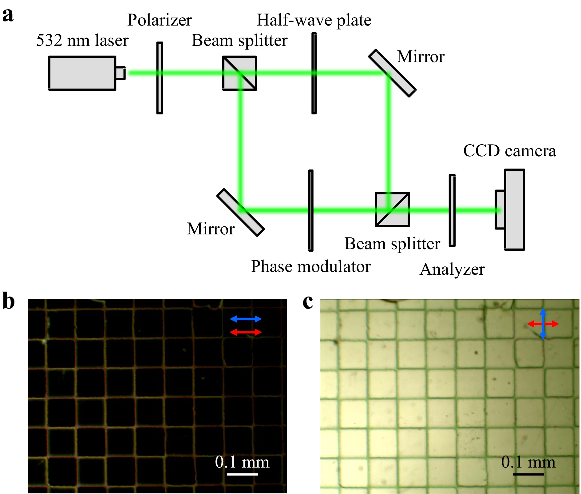
Fig. 6 a System for measuring polarization independence; MMOT structure phase modulator with the polarizer b parallel and c orthogonal to the polarization direction of incident light under POM.
Fig. 6b shows a polarized optical microscope (POM) image of the phase modulator with the MMOT structure. The red arrow represents the polarization direction of the incident light and the blue arrow indicates the direction of the polarizer. When these two directions are parallel, the grids are dark because of the 90° twist structure of the LCAA. The bright boundaries in Fig. 6b and dark boundaries in Fig. 6c are caused by a sudden change in the arrangement of the liquid crystal molecules between the adjacent orthogonal microdomains. This indicates that the liquid crystals were not arranged with 90° twisting in these areas. When a voltage was applied to the cell, the phase retardation and polarization exchange differed from those at the center of the pixels, which influences the polarization independence of the device. Because the boundaries occupied only a small portion of the entire device, this effect was minimal.
-
The polarization independence was measured using two linearly polarized lights with orthotropic directions. The X direction is defined as the polarized state parallel to the alignment of the top substrate of the TN device, while the Y direction is defined as the polarized state perpendicular to the alignment of the top substrate of the TN device. All polarized light can be obtained by combining these two linearly polarized light sources with specific phases and intensities. The polarization dependence was calculated using Eq. (3).
$$ {P_D} = \frac{{\left| {{P_{\text{x}}} - {P_y}} \right|}}{{{P_{\text{x}}} + {P_y}}} $$ (3) where PD is the polarization dependence. Px and Py represent phase retardation with linearly polarized light in the X and Y directions, respectively.
As shown in Fig. 7a, when the applied voltage was increased from 0 V to 4 V, the phase retardations of the phase modulator with the MMOT structure in the X and Y directions increased from 0 to 4.16π and 3.83π, respectively. The phase modulations in the two directions exhibited similar tendencies. The slight difference in the phase retardation in the X versus Y directions is caused by the discrepant rotation angle of the CLC and the differences between the adjacent microdomains, which can be eliminated with a more rigorous fabrication process. However, the phase retardations of the phase modulator (with the TN structure) in the X and Y directions increased from 0 to 4.01π and 0.67π, respectively. The phase modulations in the two directions exhibited different tendencies. By using the phase retardation data in Fig. 7a and Eq. 2, the polarization dependence was calculated. Because the phase retardation is defined as 0 when the applied voltage is 0 V, the polarization dependence was calculated as 0.1 V. As shown in Fig. 7b, when the applied voltage was higher than 0.5 V, the polarization dependence of the phase modulator with the MMOT structure was lower than 10%, where the average phase retardation in the X and Y directions was ~3.4π. The polarization dependence of the phase modulator with the TN structure was higher than 70% at applied voltages from 0.1 V to 4 V due to the differences in the phase modulation trends in the X and Y directions.
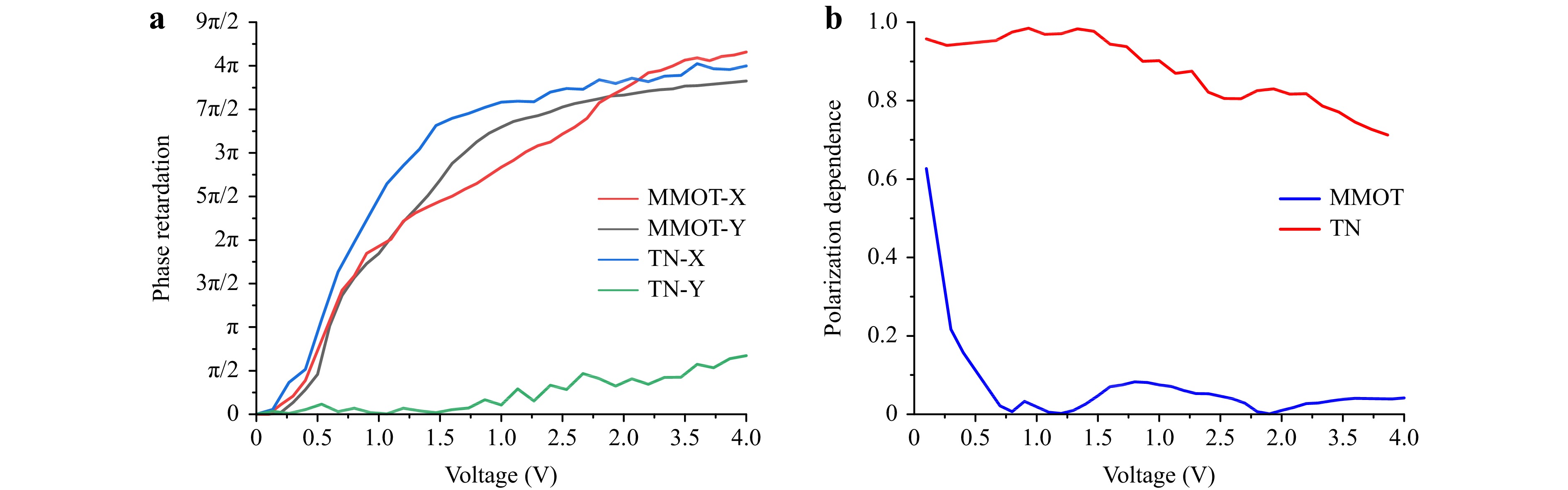
Fig. 7 a Phase retardation of MMOT structure and TN device. b Comparison of polarization dependence for MMOT structure device versus TN device.
The MMOT-structured polarization-independent phase modulator realizes a larger phase retardation with a lower applied voltage compared with TN LC phase modulators14 and PS-BPLC phase modulators16. Compared with double-layer polarization-independent liquid-crystal phase modulators20, the MMOT structure phase modulator can achieve a similar polarization independence with a simpler structure and lower driving voltage, but the optical efficiency is lower. Compared with nematic orthogonal photoalignment phase modulators23, the process for fabricating the MMOT structure phase modulator is greatly simplified because the LCAA process realizes self-alignment on the top and bottom layers.
-
An LCAA process based on the optical rotatory effect of CLC was developed for fabricating single-layer MMOT structures. The LC phase modulator with the single layer MMOT structure can achieve a polarization dependence of less than 10% with 3.4π phase retardation. This device shows great potential for applications in optical communications, wearable devices, and displays.
-
This study was supported by the National Natural Science Foundation of China under Grant No.62175148.
Polarization-independent liquid-crystal phase modulator with multi-microdomain orthogonally twisted photoalignment
- Light: Advanced Manufacturing 4, Article number: (2023)
- Received: 20 July 2023
- Revised: 09 October 2023
- Accepted: 09 October 2023 Published online: 15 November 2023
doi: https://doi.org/10.37188/lam.2023.035
Abstract: Polarization-independent liquid-crystal (LC) phase modulators can significantly improve the efficiency and reduce the complexity of optical systems. However, achieving good polarization independence for LC phase modulators with a simple structure is difficult. A light-controlled azimuth angle (LCAA) process based on the optical rotatory effect of cholesteric liquid crystals (CLC) was developed for fabricating single-layer, multi-microdomain, orthogonally twisted (MMOT) structures. The developed LC phase modulator with a single-layer MMOT structure may have a low polarization dependence with a large phase depth. This device shows good potential for applications in optical communications, wearable devices, and displays.
Research Summary
Polarization-independent modulation: Multi-microdomain, orthogonally twisted liquid crystal modulator
The liquid crystal spatial light modulator has excellent phase modulation characteristics and is widely used in optical modulation, beam shaping, and computational displays. However, the polarization-independent device structure based on twisted nematic liquid crystal often faces challenges such as complex fabrication processes, complicated device structures, and insufficient phase modulation depth. Professor Jian-gang Lu 's team from Shanghai Jiao Tong University has proposed a fabrication process for a polarization-independent liquid crystal phase modulation device. A light-controlled azimuth angle process based on the optical rotatory effect of cholesteric liquid crystals is developed for fabricating single-layer, multi-microdomain, orthogonally twisted structures. The developed phase modulator has a low polarization dependence with a large phase depth. This device shows good potential for applications in optical communications, wearable devices, and displays.
Rights and permissions
Open Access This article is licensed under a Creative Commons Attribution 4.0 International License, which permits use, sharing, adaptation, distribution and reproduction in any medium or format, as long as you give appropriate credit to the original author(s) and the source, provide a link to the Creative Commons license, and indicate if changes were made. The images or other third party material in this article are included in the article′s Creative Commons license, unless indicated otherwise in a credit line to the material. If material is not included in the article′s Creative Commons license and your intended use is not permitted by statutory regulation or exceeds the permitted use, you will need to obtain permission directly from the copyright holder. To view a copy of this license, visit http://creativecommons.org/licenses/by/4.0/.

 DownLoad: