


-
Optical vortex beams, with unique characteristics such as a central singularity, orbital angular momentum (OAM), and helical wavefronts, have attracted increasing research interest in recent years. They have found diverse applications in fields ranging from optical communications1-6, optical trapping7,8 to quantum optics9-11. High-power OAMs are particularly suitable for processing materials. Compared with Gaussian beams for laser ablation, vortex beams can drill deeper and generate smoother processed surfaces12. Their orbital and spin angular momenta can also be transferred during material processing, thereby creating exotic chiral nano-structures13,14. Furthermore, the peculiar beam structure of superimposed vortex beams allows the fabrication of 3D microstructures without the need to scan through each point individually, increasing the flexibility and efficiency15,16.
Vortex beams can be obtained by modifying existing laser beams using intricate optical elements such as q-plates17, spiral phase plates18,19, fork holograms20, spatial light modulators21,22, and metasurfaces23-25. Although these can provide customised and refined control of the phase and amplitude of the beam, they also possess notable disadvantages. In addition to the high costs associated with many of these elements, their relatively low conversion efficiencies and damage thresholds limit their utilisation in applications requiring high power. Furthermore, the transmitted beams can be sensitive to instabilities arising from scattering within the elements26.
Alternatively, since Laguerre-Gaussian (LG) beams — a typical type of vortex beams — are eigenmodes of a laser cavity, they can be directly generated from a laser. These beams can exhibit cleaner modes since the laser cavity acts as an effective filter27. Just as importantly, the oscillator can be induced to excite the desired higher-order modes with relatively simple optics, such as by implementing annular pumping28, non-collinear pumping29,30, defect-spot mirrors31, or taking advantage of how thermal lensing affects different modes differently32. Even without using exotic optical elements, complex vortices with topological charges up to 288 have been achieved33. The elimination of fragile elements also enabled the raising of the output vortex beam power in solid-state lasers. With the annular-ring pumping scheme, a 2.7-W optical vortex beam was generated directly from a diode-pumped Yb:MgWO4 laser34, and a 16.7-W vortex beam was generated from a Tm:YALO3 laser at 2 μm35. Additionally, generation of a vortex beam from a Nd:YVO4 laser with an output power of up to 31 W has been reported using an interferometric mode-transforming output coupler36. Besides, a vortex beam with a power of 30 W was generated from a Ho:Y2O3 ceramic laser using a capillary fiber and lens-combination scheme37.
Nevertheless, at these power levels, vortex laser systems face thermal issues similar to those of other solid-state lasers, making it a challenge for further power scaling. These issues can be mitigated by adapting the thin-disk geometry for the gain medium38-40, where the effective and one-dimensional heat flow allows the maintenance of a good output beam profile41,42 even at powers exceeding the kilo-Watt level43. The larger spot sizes commonly used in thin-disk lasers compared to those of bulk-crystal lasers also allow for more flexibility in selecting the desired higher-order modes. A Yb:YAG thin-disk oscillator was constructed to generate radially polarized beams with an output power of 107 W using a polarizing grating waveguide mirror (GWM)44. A large-area GWM-enabled power scaling in a Yb:LuAG thin-disk oscillator, which delivered radially polarized beams with powers of up to 980 W45. Using a circular grating waveguide output coupler, radially polarized pulses were generated from a passively mode-locked thin-disk laser oscillator using a semiconductor saturable absorption mirror, emitting sub-picosecond pulses with an average output power of ~100 W46. These studies demonstrate the potential of thin-disk technology for generating high-power structured beams. However, the use of modulating elements increases the system complexity, and the helical wavefront and OAM characteristics have not been obtained.
In this letter, we report the generation of a 100-W level LG vortex beam directly from a thin-disk laser, which to the best of our knowledge is the highest-power optical vortex obtained directly from a laser. This was achieved without any specially designed elements for modulating the optical amplitude and phase. By adjusting the mirrors and aperture of the resonator, we can select optical vortices with topological charges of 1 or −1. There is ample room for further power scaling, and the system can be adapted in the future to generate beams with higher topological charges.
-
The setup of the Yb:YAG thin-disk vortex laser is shown in Fig. 1. The 220-μm thin Yb:YAG disk crystal has a Yb3+ doping concentration of 7% (Dausinger + Giesen, Stuttgart, Germany), and is placed inside a 48-pass pump module47. It is pumped by a fiber-coupled diode laser at a wavelength of 940 nm with a maximum output power of 500 W. The pump spot diameter on the disk is adjusted to ~3.3 mm by tuning the collimating lens system. The Yb:YAG disk is high-reflection coated at the lasing wavelength (1030 nm) and used as a folding mirror in a Z-shaped cavity containing a focusing section formed by two concave mirrors (CM). The other mirrors are high-reflection mirrors (HR) at 1010-1070 nm, except for the output coupler (OC), which has a transmittance of 15%. A water-cooled copper aperture (HA) with a diameter of 2.9 mm is placed inside the cavity to assist the selection of the LG vortex beams. The output laser beam is separated by a wedge, with a fraction of the power injected into a homemade Mach-Zehnder (MZ) interferometer, followed by a charge-coupled device (CCD) camera to confirm the profile of the spiral phase. The MZ interferometer is comprised of two half-to-half nonpolarizing beam splitters (NPBS), a convex lens (F1), and two HR-turning mirrors. The LG beam is divided into two identical beams by the first NPBS. One beam is directly incident on the CCD. The other beam passes through F1 to enlarge its cross section, which creates an approximate reference spherical wave or plane wave depending on the horizontal distance between F1 and the CCD camera. It is coherently and collinearly combined with the first beam before reaching the CCD camera. With this MZ interferometer, the spiral interference pattern and the chirality can be characterized.
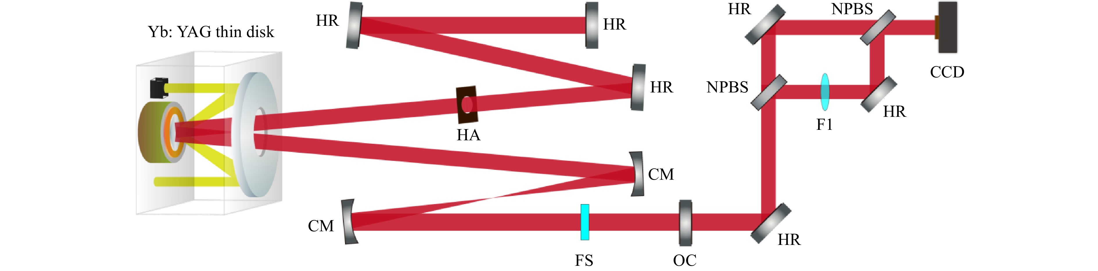
Fig. 1 Setup of the vortex thin-disk oscillator and the homemade MZ interferometer. CM, concave mirrors with a radius of curvature of -150 mm; OC, output coupler with an output coupling ratio of 15%; HR, high-reflection mirrors; NPBS, non-polarization beam splitter with 45° incidence angle and splitting ratio of 50%; HA, hard aperture with a diameter of 2.9 mm; F1, convex lens with 50 mm focal length. The distance between the two concave mirrors is approximately 152 mm. The FS is anti-reflection coated for laser wavelength on both sides with a thickness and diameter of 2 mm and 0.5 inch, respectively.
Whether the LG or other transverse modes oscillate in the laser cavity depends on their gain integrals. Generally, the fundamental mode (LG00) dominates, because it has the lowest threshold owing to the preferred mode matching between the laser and pump beam. For the LG0l mode, the threshold pump power $ {P}_{pth} $ is given by Ref. 48:
$$ {P}_{pth}=\frac{h{\nu}_{p}{I}_{0}}{{\tau }_{c}{\eta }_{q}\left[1-\mathit{exp}\left(-{\alpha }_{p}{d}_{0}\right)\right]}{\left[{\int }_{cavity}^{}{r}_{p}\left(x,y,z\right){s}_{0}\left(x,y,z\right)dV\right]}^{-1} $$ (1) where $ h $ is the Planck constant; $ {\nu }_{p} $ is the pump frequency; $ {d}_{0} $ is the length of the thin-disk gain medium; $ {\alpha }_{p} $ is the absorption coefficient for the pump in the disk medium; $ z $ is the axial distance perpendicular to the disk surface; $ {\tau }_{c} $ is the cavity photon lifetime; $ {I}_{0} $ is the saturation intensity, and $ {\eta }_{q} $ is the fraction of absorbed pump photons that leads to the subsequent population of the upper laser level. The normalized distributions of the pump and laser beams, $ {r}_{p}\left(x,y\right) $ and $ {LG}_{0l}\left(x,y\right) $, are given by
$$ {\int }_{disk}^{}{r}_{p}\left(x,y\right)dS\equiv 1 $$ (2) $$ {\int }_{disk}^{}{LG}_{0l}\left(x,y\right)dS\equiv 1 $$ (3) The LG0l beam modes oscillating in a cavity consisting of circular plane mirrors are described by the following equation49:
$$ {LG}_{0l}\left(r,\varphi \right)={E}_{r}\mathit{exp}\left(il\varphi \right),\left(l=integer\right) $$ (4) where $ {E}_{r} $ is the invariant field distribution. The beam mode has a phase term $ exp\left(il\varphi \right) $ associated with the azimuthal angle, and can be calculated by solving the scalar Helmholtz equation under the paraxial approximation50 and expressed as:
$$ \begin{aligned}{LG}_{p=0,\pm l}=&\sqrt{\frac{2!}{\pi \left(\left|l\right|\right)!}}\frac{1}{\omega \left(z\right)}{\left(\frac{\sqrt{2}r}{\omega \left(z\right)}\right)}^{\left|l\right|}\mathit{exp}\left(\frac{{-r}^{2}}{{\omega \left(z\right)}^{2}}-\frac{ik{r}^{2}z}{2\left({z}_{R}^{2}+{z}^{2}\right)}\right) \\\times& {L}_{0}^{\left|l\right|}\left(\frac{{-2r}^{2}}{{\omega \left(z\right)}^{2}}\right){exp}\left[-i\left(\left|l\right|+1\right)ta{n}^{-1}\left(\frac{z}{{z}_{R}}\right)\right]{exp}\left(\mp il\varphi \right) \end{aligned}$$ (5) where $ r $ and $ \varphi $ are the radial and azimuthal coordinates, $ k $ is the wavenumber, $ {z}_{R} $ is the Rayleigh range, $ \omega \left(z\right) $ is the 1/e radius of the beam at position $ z $, $ p $ is the radial order, and $ l $ is the azimuthal angular order with $ p=0 $. The high order modes with $ p=0 $ and a nonzero $ l $ comprise an azimuthal phase term $ \mathit{exp}\left(\mp il\varphi \right) $, and possess an orbital angular momentum of $ \pm l\hslash $ for each photon, which corresponds to the spiral phase front. The radius of LG0l is calculated by the following equation:
$$ \omega \left(z\right)={\omega }_{0,l}\left(z\right)=\sqrt{\left|l\right|+1}{\omega }_{\mathrm{0,0}}\left(z\right) $$ (6) where $ {\omega }_{\mathrm{0,0}}\left(z\right) $ is the radius of the fundamental laser beam calculated using “ABCD” beam transfer matrices. As mentioned previously, the thin-disk gain medium is pumped by a multimode fiber laser through a 48-pass module, with the resulting pump beam having an approximately top-flat profile. Hence, the intensity distribution of the pump beam can be expressed as
$$ {r}_{p}(x,y)=\frac{1}{\pi {r}_{pump}^{2}} $$ (7) In our experiment, we fixed the pump beam radius on the thin-disk medium and varied the laser beam size on the thin disk by adjusting the distance between the two concave mirrors within the range of the stability zone or by using concave mirrors with different radii of curvature. In reality, there is a certain curvature of the gain crystal owing to processing tolerances, which can lead to a small difference between the actual mode size in the resonant cavity and the calculated size.
To stimulate higher-order transverse modes inside the thin-disk oscillator, the ratio of the fundamental laser beam to the pump spot size should be decreased; in other words, the pump spot should be larger than the LG00 mode size. As can be seen from Fig. 2c, when the radius of the LG00 beam is 325 μm (a ratio of 19.7%), the LG02 beam has the lowest threshold, and can oscillate first in the cavity. By contrast, when the radius of the LG00 beam is increased to 625 μm (the ratio increased to 37.9%), the threshold of the LG01 mode decreases while that of high-order beam increases. Thus, to generate a pure LG01 beam, we decreased the radius of the LG00 beam gradually to ensure that the other beam-mode thresholds were always higher than that of the LG01 mode. This was achieved by changing the distance between the two concave mirrors and forcing the oscillator to operate in different stability regions with different intracavity laser mode sizes. A water-cooled copper aperture was added to further refine the control of the oscillating modes and suppress any residual higher-order beams.
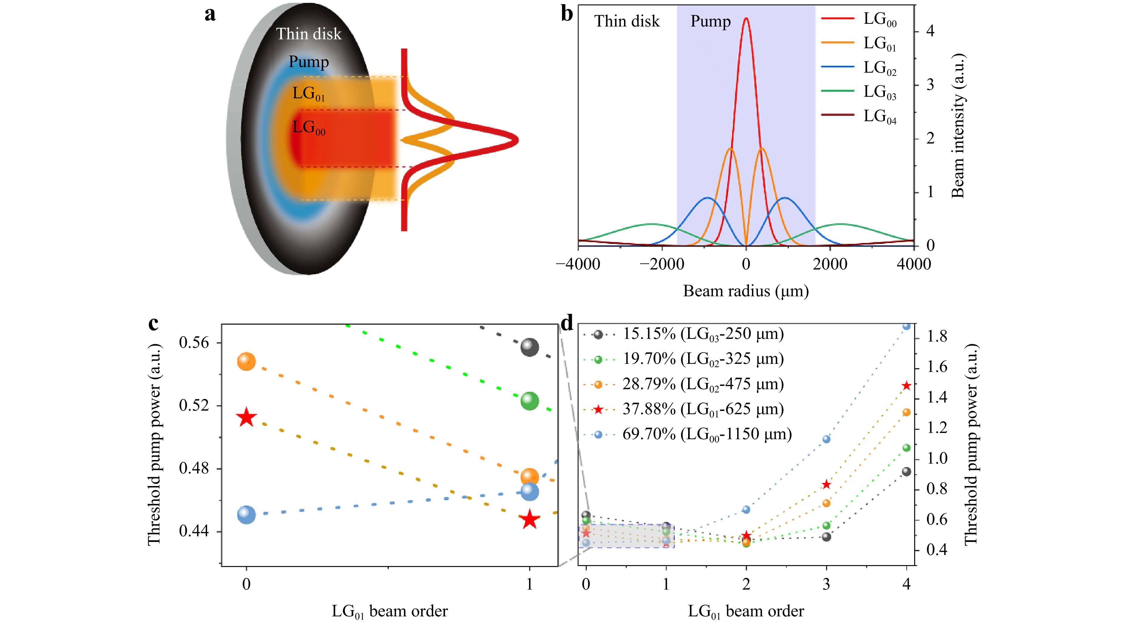
Fig. 2 a Schematic of the pump beam (blue area) and LG0l beam (red area and orange area) on the thin disk gain medium (black area). b Corresponding beam cross-sections of the LG0l (l = 0-4) beam. The shaded area indicates the pumped region. c d Lasing thresholds of each order of the LG0l beam at different ratios between the sizes of the LG00 mode and the pump mode.
-
Initially, the oscillator emitted in the LG00 mode stably (Fig. 3a) with a lasing threshold pump power of 30 W and an output power of 6 W. As the pump power increased, the beam profile changed from the standard LG00 mode to the top-hat mode (Fig. 3b) and later to the imperfect LG01 mode with a low-intensity contrast between the ring and center part of the beam profile (Fig. 3c). The output mode became the standard LG01 at a pump power of 105 W with the output power of 18 W (Fig. 3d). This process can be explained as follows. The various transverse modes in the oscillator are influenced by both the diffraction losses and gains mentioned above. At low pump powers near the lasing threshold, the effect of diffraction loss is more pronounced. The low-order LG00 mode experiences a lower diffraction loss, and has advantages in terms of mode competition. Thus, it is the first to experience lasing, emitting a beam that has a bright central region. As the pump power increases, the influence of the mode-dependent gain dominates the mode competition dynamics. At this point, the LG01 mode overcomes the lasing threshold and appears simultaneously with the LG00 mode, gradually leading to a top-hat profile for the combined beam. With a further increase in the pump power, the power growth of LG01 is more rapid than that of the LG00 and other modes, and it consumes more of the available gain in the laser medium, suppressing other modes and leading to the emission of the pure LG01 mode.
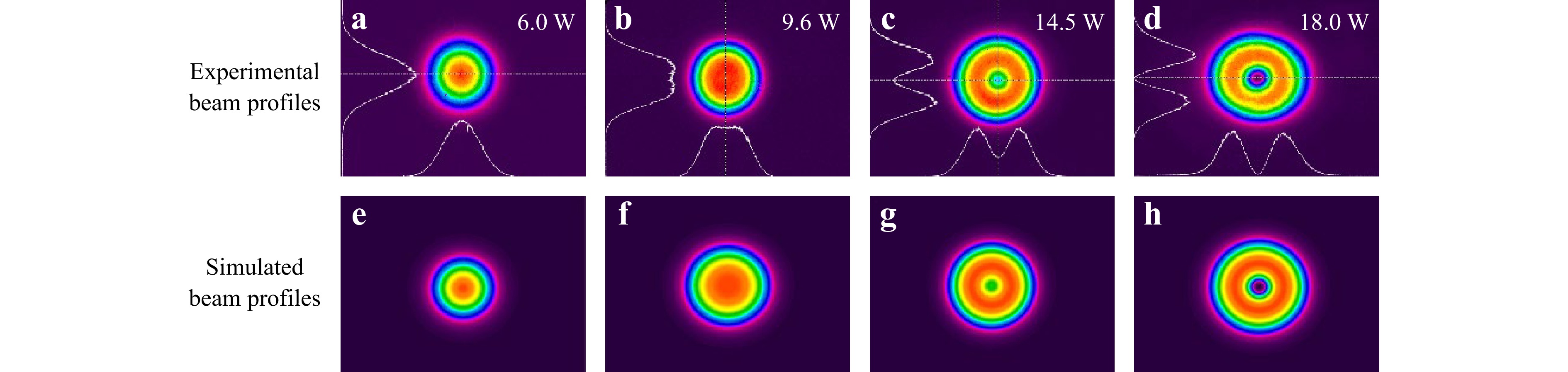
Fig. 3 a−d Output beam profiles at an output pump power of 6.0 W, 9.6 W, 14.5 W, 18.0 W, respectively. e−h Simulated beam profiles as a combination of the LG00 and LG01 modes.
A numerical simulation based on the model presented in Ref. 51 was performed to characterize this process by expressing the total beam profile as a combination of the LG00 and LG01 modes.
$$ {I}_{\left(\mathrm{0,0}\right)\to \left(\mathrm{0,1}\right)}\left(r\right)={I}_{\mathrm{0,0}}\left(r\right)+\sigma {I}_{\mathrm{0,1}}\left(r\right) $$ (8) where $ {I}_{\mathrm{0,0}} $ and $ {I}_{\mathrm{0,1}} $ are the normalized intensity profiles of the LG00 and LG01 modes respectively, and $ \sigma $ is an empirically deduced scaling factor determining the relative intensity of the two modes. The simulated combined beam profiles with the best matching $ \sigma $ value are shown in Fig. 3e−h, matching well with the experimentally measured profiles. Fig. 4a, b display the cross sections along the x-axis for the experimental and simulated beam profiles, respectively, indicating a good match between the two.
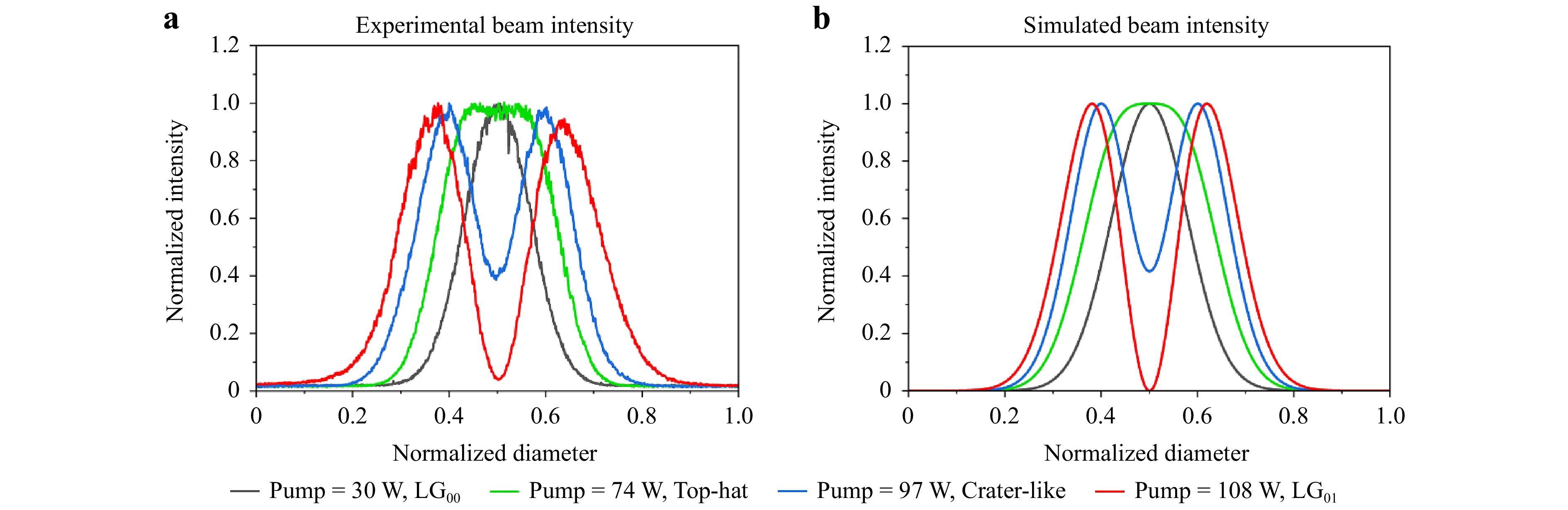
Fig. 4 a Experimental and b theoretical central beam intensity distributions, respectively.
After the initial process, we obtained a high-power pure LG01 mode with the increase of the pump power. The power measurement results are shown in Fig. 5; a maximum output power of 101 W was achieved at a pump power of 310 W. The overall relationship between the output power and pump power is linear. The slope and optical-to-optical efficiencies are 40.7% and 33.3%, respectively. As shown in the graph, the output power does not saturate even at the maximum pump power, indicating a large potential for higher-power vortex beam generation. At the maximum output power of 101 W, the power was continuously recorded within one hour (Fig. 6a), showing a good stability of 0.37% (root mean square, rms). We have also measured the output spectrum of the vortex beam using a commercial optical spectrum analyzer with a resolution of 0.02 nm (Fig. 6b). The laser spectrum is centered at a wavelength of 1030.516 nm with a bandwidth of 0.14 nm at full width at half maximum. Fig. 7 shows the beam profiles of the output vortex laser at different power levels. At an output power of 49 W, a slight distortion in the beam profile began to appear (Fig. 7d). This was likely due to thermally induced stress in the gain crystal, and we did not increase the pump power beyond 310 W to prevent damage. As the next step, we investigate the optimization of water cooling to suppress thermal effects and pursue higher-power LG-mode vortex beams.
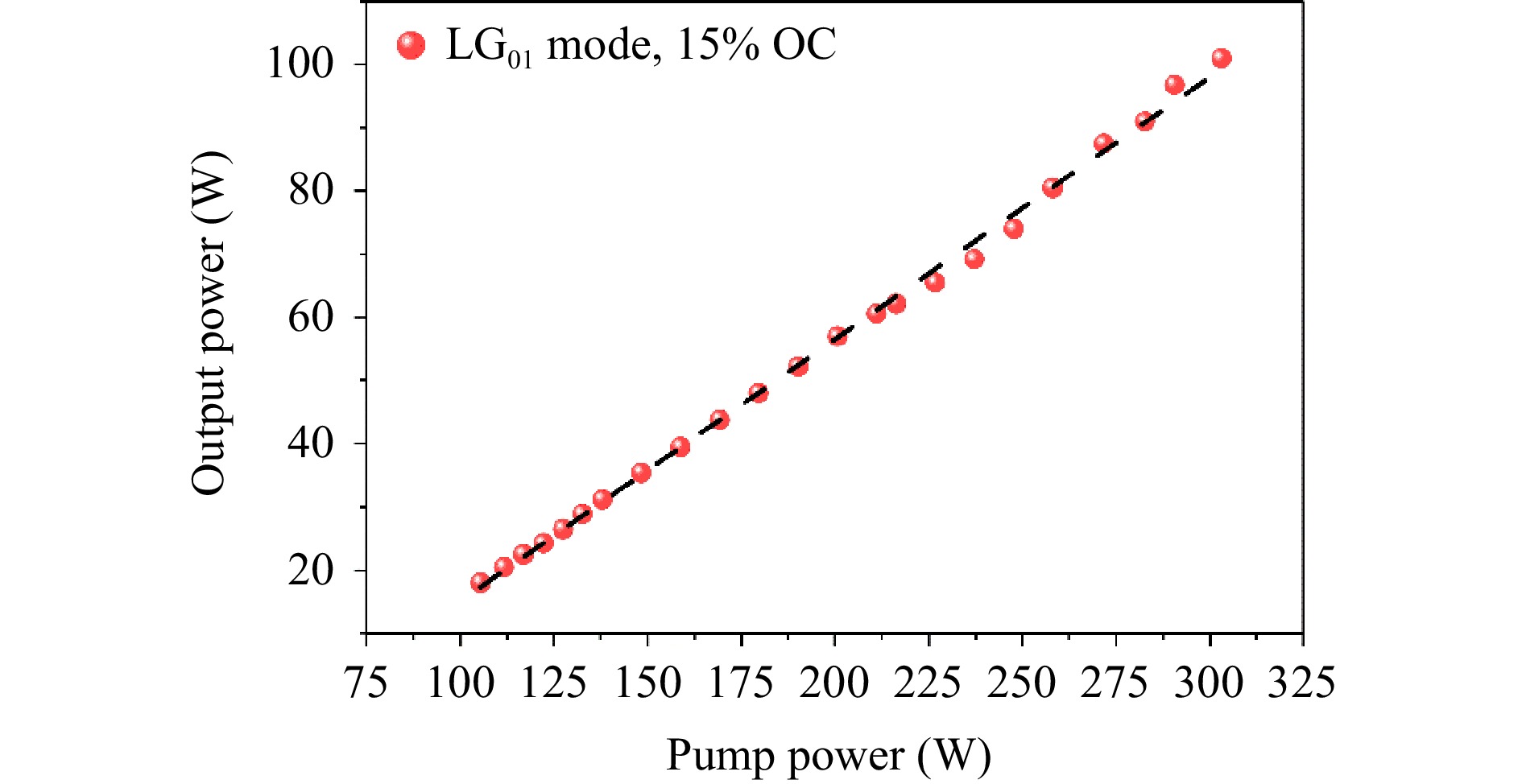
Fig. 5 Output power of the LG01 mode as a function of the pump power.
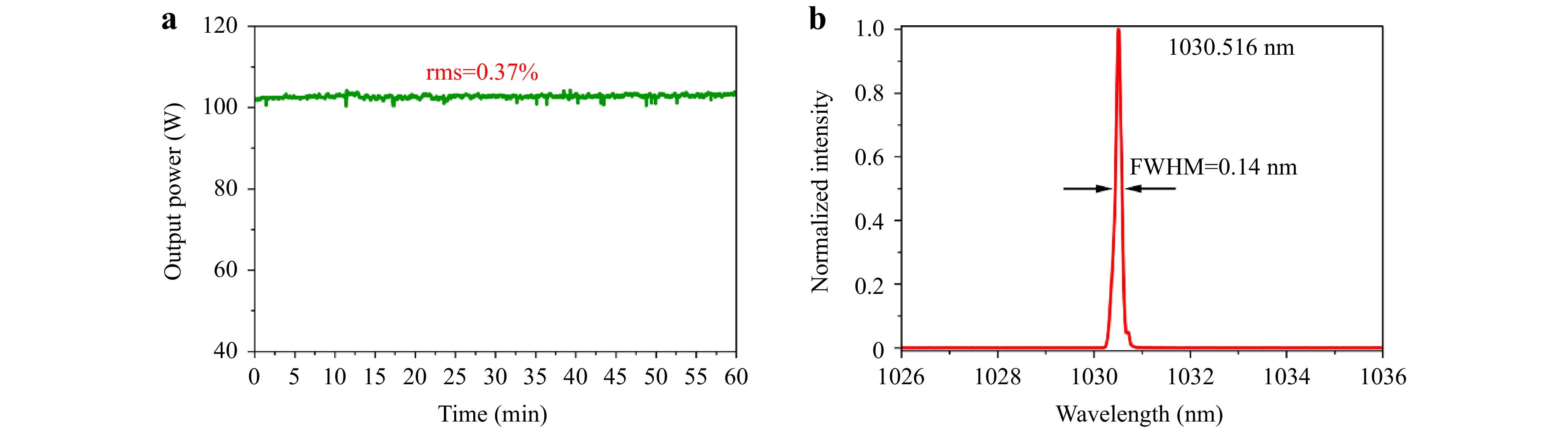
Fig. 6 a Power stability measurement at the maximum output power. b Measured spectrum at the maximum output power.
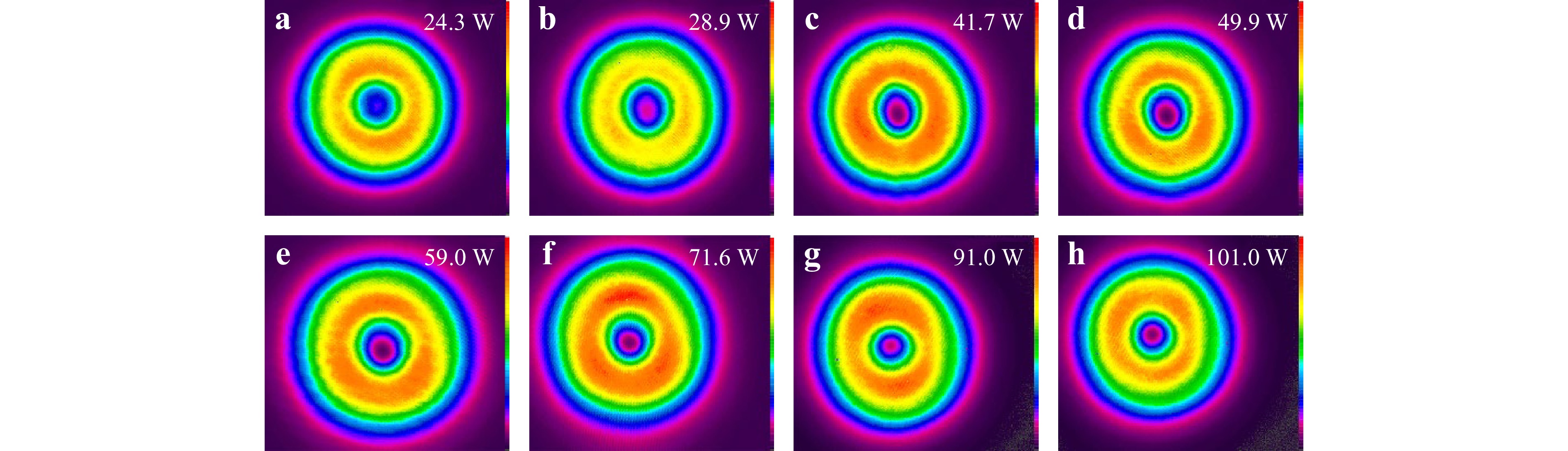
Fig. 7 Output beam profiles of the LG01 mode at various output powers.
To determine the chirality of the output vortex laser beam, an antireflection-coated fused-silica plate was inserted into the cavity in front of the output coupler. Initially, the surface of the plate was normal to the beam path. By adjusting the tilt angle of the plate to 2.5° or −2.5°, we can respectively obtain either the LG01 or the LG0-1 mode. Fig. 8 shows the interferograms between the 101-W LG mode (beam vortex chirality of both l = 1 and l = −1) with either a plane wave (Fig. 8i−l) or spherical wave (Fig. 8e−h). Under plane-wave interference (Fig. 8i−l), a pair of Y-shaped forks with opposite orientations can be observed. In the case of spherical wave interference (Fig. 8e−h), a spiralling pattern in either the counterclockwise or clockwise direction can be observed, with the number of spiral arms equivalent to the topology charge $ \left|l\right| $. The experimental results are in very good agreement with the simulated results, as shown in the third and fourth columns of Fig. 8. We also measured the radial intensity contrast of the vortex, which is approximately 11.4 dB and 11.2 dB along the x- and y- axes (Fig. 9a). The generated vortex beam has excellent beam quality at an output power of 101 W with $M_x^2 $ = 2.09 and $M_y^2 $ = 2.02 (Fig. 9b), which is close to the ideal value (M2 = 2).
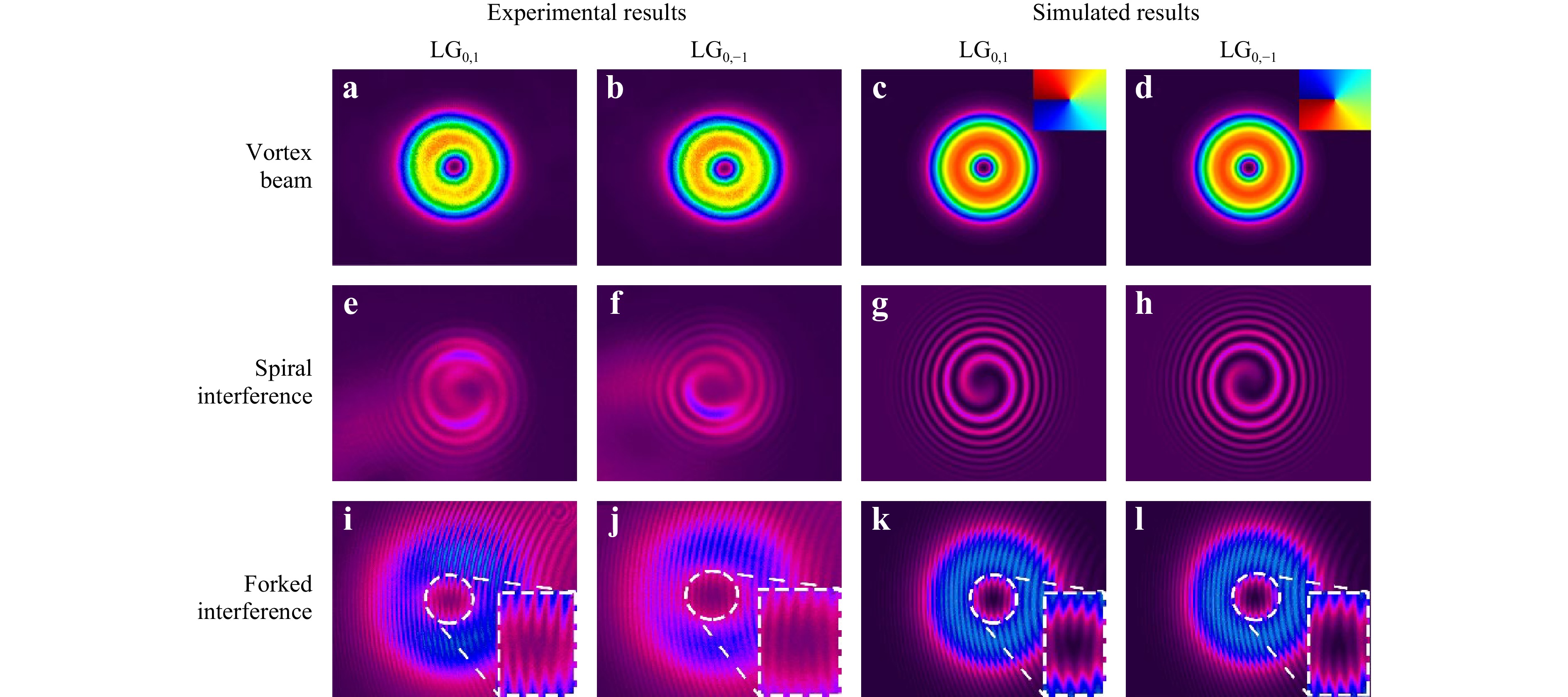
Fig. 8 Beam profiles and interference patterns of the LG beams. a−d Measured and simulated intensity distribution of the LG01 and LG0-1 beams. e−h Measured and simulated spiral phase structure of the LG01 and LG0-1 beams when interfered with a spherical wave. i−l Measured and simulated spiral phase structure of the LG01 and LG0-1 beams when interfered with a plane wave.
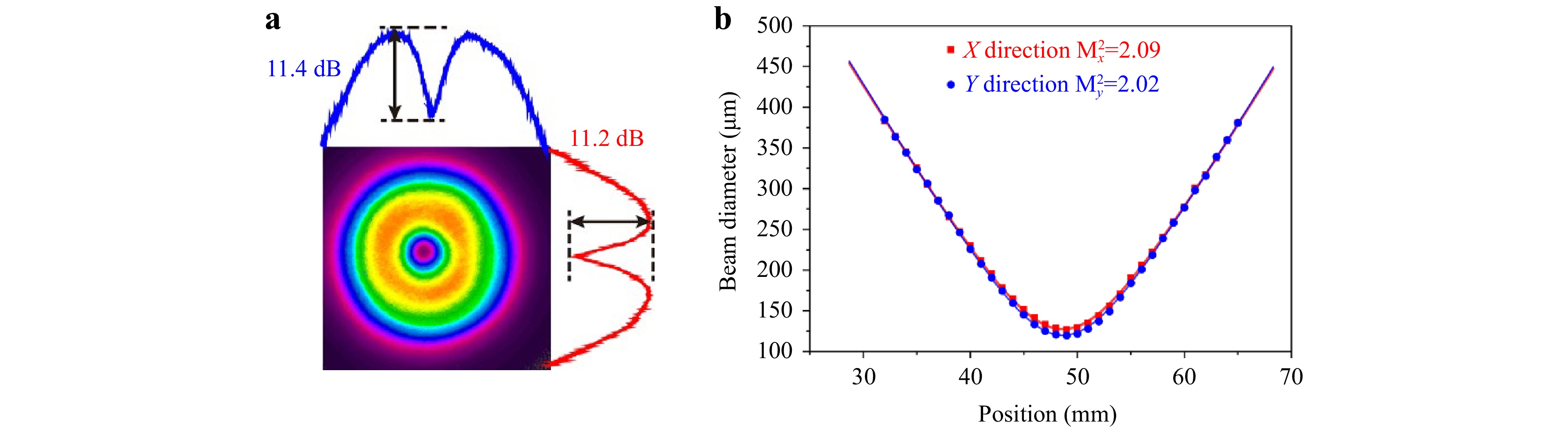
Fig. 9 a Radial distribution of the spatial intensity for the LG vortex beam at an output power of 101 W. b Beam quality measurement of the 101-W LG vortex beam.
Such a laser source is beneficial for applications in optical ablation and microstructure manufacturing, because the OAM of photons can be transferred to the processed material. For high-efficiency optical ablation, a high-power vortex beam enables high-quality processing with less debris, a clearer outline of the ablated zone, and a smoother surface, owing to the effect of rotational motion12. Additionally, a high-power vortex laser beam can twist the metal to form chiral nanoneedles during the ablation process14. Besides, compared to the Gaussian beam, the vortex beam has a significant advantage in drilling submillimeter-sized through-holes on stainless steel without moving the optical system52.
The vortex beam power in this experiment is not yet saturated, and a higher pump power is withheld to avoid damaging the disk crystal. In the future, we will optimize the crystal coolant temperature and increase the pump spot area on the disk crystal so that a higher absolute pump power can be applied. Based on this, a new resonant cavity can be designed to optimize mode matching to the largest possible pure LG01 mode, together with the implementation of hard apertures with more precise diameters for finer mode selection. The system can also be combined with active multipass cell53 technology to increase the output efficiency and power. With these measures, the direct generation of a vortex beam from a thin-disk oscillator with an output power higher than 1 kW is expected in the future.
The generation of significantly higher topological orders is also feasible based on the thin-disk architecture demonstrated in this study. According to the model presented in this work, the mode size ratio of the fundamental laser beam to the pump spot size should be decreased to stimulate higher-order transverse modes. This can be achieved by increasing the pump spot size or decreasing the laser spot size with a suitable cavity design. Additionally, a ring-shaped pump beam can be applied to achieve mode matching between the pump beam and high-order vortex beam. Furthermore, a defect-spot mirror and hard aperture of suitable size can also be utilized to suppress the oscillation of the low-order or undesired high-order modes.
-
In conclusion, we directly generated a 100-W-level LG01 mode vortex laser beam with high beam quality from a Yb:YAG thin-disk laser oscillator without using any specially designed optical phase element. By adjusting the position of the cavity stability zone and utilising a copper aperture, we set the cavity to operate in the LG01 mode. The slope and optical-to-optical efficiencies of the thin-disk vortex laser oscillator were 40.7% and 33.3%, respectively. The chirality of the vortex beam was controlled by the angle of the fused silica plate within the cavity. Applying this power level to femtosecond pulses54,55 enables exciting new developments in the field of micromachining. We believe that the proposed high-power vortex laser will enhance the efficiency and flexibility of material processing, and pave the way for exploring new parameter spaces associated with structured light.
-
According to Fox–Li iteration-based algorithms, the self-reproducing process of the beam modes in a cavity consisted of circular plane mirrors is described as49
$$\begin{aligned} {u}_{q+1}=&\left(\frac{1}{\prod _{1}^{q+1}{\gamma }_{n}}\right)\upsilon \\=&\frac{i}{2\lambda }{\int }_{0}^{a}{\int }_{0}^{2\pi }{u}_{q}\left({r}_{1},{\varphi }_{1}\right)\frac{{e}^{-ikR}}{{R}_{q}}\left(1+\frac{b}{{R}_{q}}\right){r}_{1}{\rm d}{\varphi }_{1}{\rm d}{r}_{1} \end{aligned}$$ (9) With
$$ {R}_{q}=\sqrt{{b}^{2}+{r}_{1}^{2}+{r}_{2}^{2}-2{r}_{1}{r}_{2}\mathrm{cos}({\varphi }_{1}-{\varphi }_{2})} $$ (10) where $ \upsilon $ is an invariable distribution function; $ {u}_{q+1} $ and $ {u}_{q} $ are the fields after q and q+1 transits; a is the radius of the circular mirror; and b is the distance between two adjacent mirrors; $ {\gamma }_{n} $ is a complex constant independent of position coordinates.
For $ b\gg a $ and $ \dfrac{{b}^{2}}{{a}^{2}}\gg \dfrac{{a}^{2}}{b\lambda } $, the solutions to the integral equation are given by:
$$ \upsilon \left(r,\varphi \right)={T}_{n}\left(r\right)\mathrm{exp}\left(il\varphi \right),\left(l=integer\right) $$ (11) where $ {R}_{n}\left(r\right) $ satisfies the following reduced integral equation:
$$ {T}_{n}\left({r}_{2}\right)\sqrt{{r}_{2}}={\gamma }_{n}{\int }_{0}^{a}{K}_{n}\left({r}_{2},{r}_{1}\right){T}_{n}\left({r}_{1}\right)\sqrt{{r}_{1}}d{r}_{1} $$ (12) with
$$ {K}_{n}\left({r}_{2},{r}_{1}\right)=\frac{{i}^{n+1}k}{b}{J}_{n}\left(k\frac{{r}_{1}{r}_{2}}{b}\right)\sqrt{{r}_{1}{r}_{2}}{e}^{-\frac{ik\left({r}_{1}^{2}+{r}_{2}^{2}\right)}{2b}} $$ (13) where $ {J}_{n} $ is a Bessel function of the first kind and n-th order.
The invariable field is calculated by solving the scalar Helmholtz equation50 as shown in Eq. 5.
The LG0l modes with zero radial order p and a nonzero azimuthal order l are typical optical vortex laser beams comprising an azimuthal phase term $ \mathrm{e}\mathrm{x}\mathrm{p}(\mp il\varphi ) $ corresponding to the spiral phase front.
-
The Poynting vector $ \overrightarrow{S} $ for a linearly polarized LG-mode optical vortex beam is expressed as56:
$$ \overrightarrow{S}={\varepsilon }_{0}\left(\frac{{\omega }_{0l}krz}{{z}_{R}^{2}+{z}^{2}}\hat r+\frac{{\omega }_{0l}l}{r}\hat{\varphi }+{\omega }_{0l}k\hat{z}\right){\left|{LG}_{0,l}\right|}^{2} $$ (14) where $ {\omega }_{0l} $ is the angular frequency. The Poynting vector follows a spiral path along the propagation direction, and its rotation direction is determined by the sign of the azimuthal order l. Therefore, the direction of the Poynting vector is not parallel to the propagation direction. In the experiment, when no fused-silica plate was inserted, the LG01 and LG0-1 modes experienced similar losses and could be generated simultaneously. However, environmental perturbations can cause sudden jumps between the two chiral modes. Consequently, a fused-silica plate was inserted into the beam path. Its surface is almost normal to the optical beam, but is slightly tilted either in the clockwise or counterclockwise direction by ~2.5°. Thus, the symmetry in the chirality is destroyed, with one of the chiral modes experiencing an increased loss and suppression of its generation. By switching between the two FS angles, a stable output can be sustained in one of the LG chiral modes.
-
The electric field distribution of a vortex beam can be approximated by56
$$ {E}_{1}={A}_{1}\mathrm{exp}\left(\frac{-{\rho }^{2}}{{\omega }_{0}^{2}}\right)\mathrm{exp}\left(il\varphi \right) $$ (15) where $ {A}_{1} $ represents the amplitude and $ \rho =\sqrt{{x}^{2}+{y}^{2}} $. The distributions of the plane and spherical waves generated by our MZ interferometer (Fig. 1) are
$$ {E}_{2}={A}_{2}\mathrm{exp}\left(\frac{-{\rho }^{2}}{{\omega }_{0}^{2}}\right)\mathrm{exp}\left(-ikx\right) $$ (16) $$ {E}_{3}={A}_{3}\mathrm{exp}\left(\frac{-{\rho }^{2}}{{\omega }_{0}^{2}}\right)\mathrm{exp}\left(-ik\sqrt{{d}^{2}+{\left({x-x}_{0}\right)}^{2}+{y}^{2}}\right) $$ (17) where $ {A}_{2} $ and $ {A}_{3} $ represent the amplitudes of the plane and spherical waves, respectively; d is the distance between the lens generating the spherical waves (lens F1 in Fig. 1) and the CCD; and $ {x}_{0} $ is the horizontal offset of the lens relative to the beam. The intensities on the CCD due to interference between the plane waves or spherical waves with the original LG vortex beam are given by
$$ {I}_{2}={\left|{E}_{1}+{E}_{2}\right|}^{2}=\left[{A}_{1}^{2}+{A}_{2}^{2}+2{A}_{1}{A}_{2}cos\left(l\varphi +kx\right)\right]\mathrm{exp}\left(-\frac{2{\rho }^{2}}{{\omega }_{0}^{2}}\right) $$ (18) $$\begin{aligned} {I}_{3}=&{\left|{E}_{1}+{E}_{3}\right|}^{2} \\=&\left[{A}_{1}^{2}+{A}_{3}^{2}+2{A}_{1}{A}_{3}cos\left(l\varphi +k\sqrt{{d}^{2}+{\left({x-x}_{0}\right)}^{2}+{y}^{2}}\right)\right]\\&\mathrm{exp}\left(-\frac{2{\rho }^{2}}{{\omega }_{0}^{2}}\right)\end{aligned} $$ (19) In the experiment, the beam from the first NPBS that passed through the lens F1 served as the reference beam. By shifting the horizontal position of F1 away from the beam axis while maintaining the spatiotemporal overlap of the reference and LG beams on the CCD, the reference beam exhibits either spherical or plane-wave characteristics, and spiral- or fork-shaped interference patterns can be generated. Fig. 8e−h show the experimentally measured and simulated spiral patterns, respectively. The simulated results were obtained by overlapping and interfering the center of the spherical waves with that of the LG beam. Fig. 8i−l show the experimentally measured and simulated fork-shaped interference patterns, respectively. It can be seen that in both the experimental and simulated results, the fork stripes are curved instead of being straight. This is because the reference plane waves, which are generated and simulated by shifting the center of the spherical waves horizontally, are only approximations of the true plane waves. The number and direction of forks, including the direction of curvature, agreed well between the experiments and simulations.
-
This work was supported by the National Natural Science Foundation of China (Nos. 62075068 and 62335009), the National Key Research and Development Program of China (2022YFC2203902 and 2022YFC2203904), the International Science and Technology Cooperation Program of Hubei Province (No. 2021EHB004), and the Natural Science Foundation of Hubei Province (2022CFB099).
100-W Yb:YAG thin-disk vortex laser oscillator
-
Hongshan Chen1,
 ,
, - Qing Wang2,
- Xin Liu1,
- Heyan Liu1,
- Xinhua Guo1,
- Tingting Yang1,
-
Lisong Yan1, *, ,
,
-
Jinwei Zhang1, *, ,
- Light: Advanced Manufacturing 4, Article number: (2023)
- Received: 08 August 2023
- Revised: 18 November 2023
- Accepted: 20 November 2023 Published online: 29 December 2023
doi: https://doi.org/10.37188/lam.2023.040
Abstract: Optical vortices carrying orbital angular momentum and spiral wavefront phases have garnered increasing research interest owing to their numerous applications. Here, we present a simple yet effective approach to generate powerful optical vortices directly from a thin-disk laser oscillator. The demonstrated source delivered Laguerre–Gaussian beams with an output power of up to 101 W. To the best of our knowledge, this is the highest output power of all optical vortex laser oscillators. The high-power vortex output will have significant implications for laser ablation and micromachining at high throughput and for large-area applications. Additionally, it serves as a new platform for the further development of more complex high-power optical-vortex beams.
Research Summary
New powerful vortex laser source: 100-W thin-disk vortex laser oscillator
Optical vortices carrying orbital angular momentum and spiral wavefront phases have garnered increasing research interest owing to their numerous applications. Jinwei Zhang and Lisong Yan from Huazhong University of Science and Technology and colleagues now present a simple yet effective approach to generate powerful optical vortices directly from a thin-disk laser oscillator. The demonstrated source delivered Laguerre–Gaussian beams with an output power of up to 101 W, which is the highest output power of all optical vortex laser oscillators. The high-power vortex output will have significant implications for laser ablation and micromachining at high throughput and for large-area applications. Additionally, it serves as a new platform for the further development of more complex high-power optical-vortex beams.
Rights and permissions
Open Access This article is licensed under a Creative Commons Attribution 4.0 International License, which permits use, sharing, adaptation, distribution and reproduction in any medium or format, as long as you give appropriate credit to the original author(s) and the source, provide a link to the Creative Commons license, and indicate if changes were made. The images or other third party material in this article are included in the article′s Creative Commons license, unless indicated otherwise in a credit line to the material. If material is not included in the article′s Creative Commons license and your intended use is not permitted by statutory regulation or exceeds the permitted use, you will need to obtain permission directly from the copyright holder. To view a copy of this license, visit http://creativecommons.org/licenses/by/4.0/.

 DownLoad: