




-
Large-aperture telescopes serve as critical enabling technologies for a broad spectrum of applications, including astronomical observation, space science, Earth observation, exoplanet detection, gravitational-wave counterpart searches, environmental monitoring, disaster early warning, high-resolution imaging, and spectral analysis. Driven by these diverse demands, major international roadmaps and research programs have continued to promote the construction of advanced observation facilities and the development of next-generation telescope technologies.
The realization of these scientific missions depends strongly on advances in precision optical manufacturing and testing. Large-aperture optical mirrors must simultaneously meet demanding requirements in aspects such as aperture, surface figure accuracy, surface roughness, thermal stability, structural lightweight, and support accuracy. Their manufacturing therefore requires a coordinated technology chain: after the structural design and mirror blank preparation are completed, finer surface processing is carried out. In this process, surface figure error testing and geometric measurement iteratively guide and constrain manufacturing continuously to converge errors to meet high-precision surface figure standards before final acceptance.
Over the past several decades, numerous manufacturing and testing schemes have been implemented in major telescope projects worldwide. Manufacturing technologies such as computer-controlled optical surfacing, stressed-lap grinding/polishing, bonnet polishing, magnetorheological finishing (MRF), and ion beam figuring (IBF) and so on, have been widely used to improve surface figure accuracy and the efficiency of error correction during manufacturing. As iterative manufacturing progressively improves optical surface accuracy, the corresponding surface figure error detection and geometric measurements transition from high-dynamic-range profilometry at the early stage to nanometer-level wavefront sensing at the final stage. Commonly employed measurement techniques throughout this process include laser tracking, Shack-Hartmann sensing, sub-aperture stitching interferometry, and computer-generated hologram (CGH) null testing, among others. This review focuses on the manufacturing and testing technologies of large-aperture optical mirrors, with emphasis on representative telescope projects and large optical components. The Hubble Space Telescope stands as an early space telescope milestone where the demand for ultra-high surface accuracy and complex freeform metrology in an unrepairable space environment drove revolutionary breakthroughs in manufacturing and testing. Therefore, on one hand, the aperture of monolithic mirrors has continued to increase to meet growing observational demands; on the other hand, segmented mirror technology has also evolved to enable even larger apertures. Based on these representative large-aperture manufacturing cases, this review synthesizes the current technical routes, compares their advantages and limitations, and discusses their applicability to future optical systems.
Fig. 1 presents the overall framework of this review, which proceeds from application requirements to manufacturing methods, testing technologies, performance evaluation, and future outlook. Following the Introduction, Section 2 introduces the application background of large-aperture optical mirrors in ground-based and space-based observation systems. Section 3 reviews the manufacturing process of large-aperture optical mirrors, beginning with an overview of the general fabrication flow, mirror structural configurations, and key manufacturing specifications. It then surveys typical processing techniques applicable to large-aperture mirrors, organized under the categories of monolithic primary mirrors and segmented mirrors. Section 4 discusses optical testing and metrology methods used during fabrication, covering rough-stage measurement, polishing-stage testing, null and non-null testing, and segmented-mirror alignment. Section 5 summarizes key performance parameters and acceptance criteria, linking manufacturing capability with system-level optical requirements. Finally, Section 6 presents the summary and outlook, highlighting current challenges and future research directions.
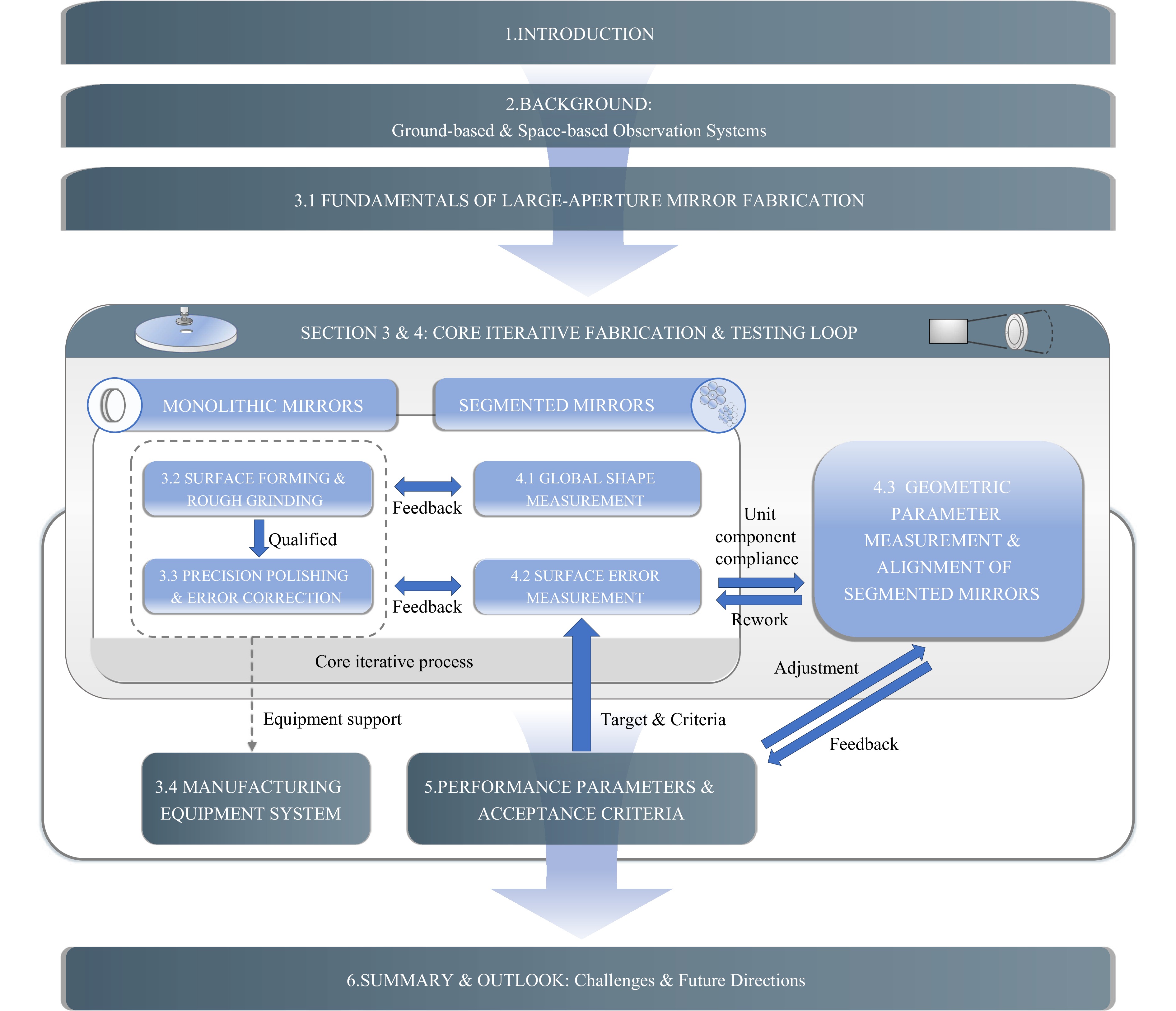
Fig. 1 Review frame.
-
Large-aperture optical mirrors are core components of modern astronomical telescopes. By increasing the collecting area and improving angular resolution, these mirrors enable telescopes to detect fainter objects, resolve finer spatial details, and acquire richer scientific data. Consequently, advances in large-aperture mirror fabrication and testing have become a key driving force behind the development of contemporary observational astronomy.
As outlined in the Introduction, this review summarizes representative manufacturing and testing methods for large-aperture optical mirrors used in major telescope systems worldwide. This section briefly introduces the scientific objectives, observational requirements, and operating wavelength ranges of representative telescopes, while emphasizing the critical role of large-aperture mirrors in meeting these requirements.
According to their operating platforms and system roles, large-aperture telescope applications can be broadly divided into ground-based and space-based optical observation systems. In addition, several large-aperture mirrors have been developed as technology demonstrators or as non-mission-specific optical components; these mirrors are discussed separately because they provide important insight into advanced fabrication and metrology strategies.
-
Ground-based optical observation systems remain indispensable in astronomy. They provide crucial data for studying the origin and evolution of the universe, the formation and structure of galaxies, stellar evolution, exoplanets, and near-Earth objects. Their major advantages include large achievable aperture, maintainability, upgradeability, and compatibility with continuously evolving technologies such as adaptive optics, high-resolution spectroscopy, and wide-field imaging.
Representative examples include the 8.4 m NSF-DOE Vera C1,2. Rubin Observatory, whose Legacy Survey of Space and Time are designed for wide-field optical and near-infrared time-domain surveys, including studies of dark matter, dark energy, transient phenomena, and small Solar System bodies; and the Gemini Observatory, which consists of twin 8.1 m optical/infrared telescopes used for multi-wavelength studies of star formation, galaxy evolution, supernovae, and exoplanets. These ground-based facilities complement space-based observatories and together form a coordinated, multi-wavelength observational framework. Additional representative ground-based telescope systems are summarized in Table 13–16.
System name (abbreviation) Maximum aperture (m) Scientific objectives Application wavelengths Gran Telescopio Canarias (GTC)3 10.4 Analyzing the spectral information of stars, galaxies, black holes, the interstellar medium, etc. Visible light, near-infrared, mid-infrared Hobby-Eberly Telescope (HET)4 9.2 Exoplanet detection, galaxy research, and supernova studies Visible light, near-infrared W. M. Keck Observatory (Keck)5 10 Investigating the origin of stars and galaxies Visible light, infrared Bolshoi Teleskop Azimutalnyi (BTA; Large Altazimuth Telescope)6 6 Monitoring unknown celestial bodies; analyzing stellar temperature and composition Visible light, infrared Subaru Telescope (Subaru)7 8.2 Studying galaxy formation and exploring other habitable planets Visible light, infrared Very Large Telescope (VLT)8 8.2 Searching for nearby stars and studying stellar birth within nebulae Visible light, near-infrared, mid-infrared Giant Magellan Telescope (GMT)9 21.4 Searching for habitable planets; black hole and neutron star research; galaxy evolution Visible light, near-infrared Southern African Large Telescope (SALT)10 11 Quasar research; studying stars and galaxies Visible light Chinese Giant Solar Telescope (CGST)17 8 Precision measurement of the solar atmosphere’s magnetic field and flow structures Visible light, infrared Southern Astrophysical Research Telescope (SOAR)12 4.1 Studying stars and galaxies Visible light, near-infrared Daniel K. Inouye Solar Telescope (DKIST)18 4 Solar magnetic field prediction Visible light, near-infrared Large Binocular Telescope (LBT)14 8.4 Studying stars and galaxies Visible light, near-infrared Extremely Large Telescope (ELT)19 39.3 Addressing fundamental issues in astrophysics Visible light, near-infrared Table 1. Scientific objectives of typical ground-based telescope systems.
Aperture values should be checked against the final citation set because different facilities report physical diameter, effective aperture, equivalent collecting aperture, or interferometric baseline in different ways.
Overall, ground-based large-aperture telescopes have continuously pushed the limits of optical fabrication, testing, alignment, and active control. They have greatly expanded the depth and breadth of astronomical observation. However, their performance is affected by atmospheric turbulence, absorption, scattering, thermal background radiation, and weather conditions. To access wavelength bands that are attenuated or blocked by the atmosphere and to achieve stable high-contrast observations, space-based telescope platforms provide an essential complement to ground-based systems. This requirement has driven the development of a new generation of space-based optical observatories.
-
Space-based optical observation systems operate above the Earth’s atmosphere and therefore avoid atmospheric turbulence, absorption, scattering, and terrestrial background contamination. These advantages enable stable high-resolution and high-sensitivity observations, particularly in wavelength bands that are difficult or impossible to observe from the ground. Space telescopes are therefore essential for studying the early universe, galaxy evolution, stellar life cycles, exoplanet atmospheres, and faint or cold astronomical objects.
The development of space telescopes illustrates the increasing demand for larger apertures and higher optical performance. The Hubble Space Telescope, equipped with a 2.4 m primary mirror, greatly improved high-resolution imaging in the ultraviolet, visible, and near-infrared bands. The Herschel Space Observatory20, with a 3.5 m silicon carbide primary mirror, extended astronomical observations into the far-infrared and submillimeter regimes and enabled studies of cold dust, molecular clouds, and early stages of star formation. The James Webb Space Telescope21, featuring a 6.5 m segmented primary mirror, further advanced infrared astronomy and has opened new opportunities for investigating galaxy formation, exoplanets, and extreme cosmic environments.
The performance of flagship missions such as the James Webb Space Telescope represents a major achievement in optical engineering. Nevertheless, future scientific goals—such as observing fainter exoplanets, resolving more distant galaxies, and probing earlier stages of cosmic evolution—will require further improvements in aperture, wavefront control, thermal stability, deployment accuracy, and system-level optical performance. These requirements place increasingly stringent demands on optical fabrication and testing technologies, especially for lightweight, segmented, and deployable large-aperture mirrors.
-
In addition to mirrors developed for specific telescope systems, several large-aperture mirrors have been fabricated as technology demonstrators or as representative components for future optical systems. Although they may not be directly associated with a single finalized telescope platform, their development addresses key technical challenges and provides valuable experience for advanced manufacturing and metrology. The diverse landscape of these next-generation systems and the key component technologies they drive are visualized in Fig. 2, which provides a framework for understanding the progression from system concepts to enabling manufacturing and metrology demonstrators.
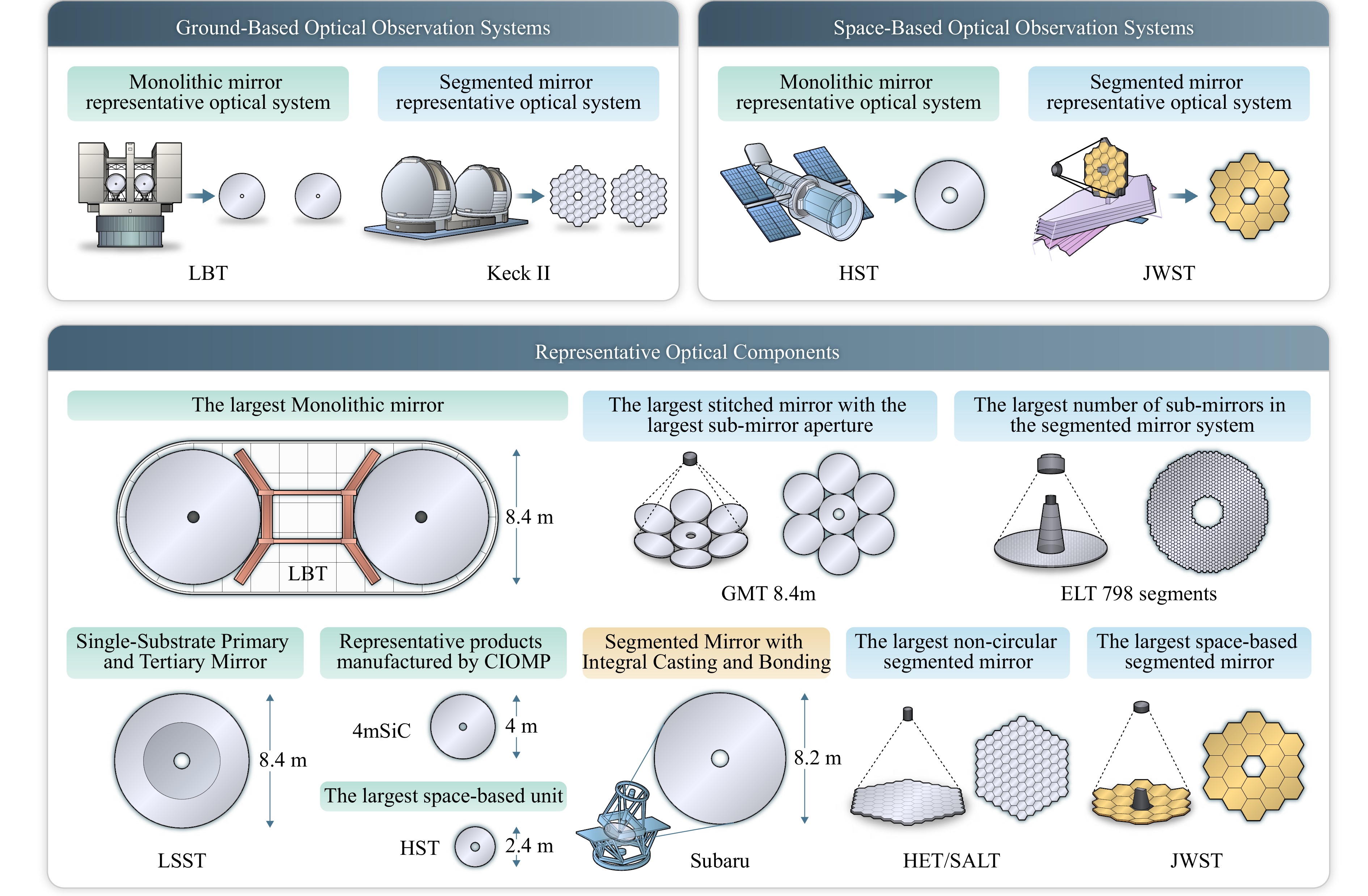
Fig. 2 Application prospects of emerging manufacturing and testing technologies in the field of large-aperture optics.
One representative example is the 4.03 m silicon carbide (SiC) aspheric mirror developed by the Changchun Institute of Optics, Fine Mechanics and Physics (CIOMP), Chinese Academy of Sciences22. This mirror represents a significant achievement in large-scale SiC mirror fabrication. Its lightweight mirror blank was produced using gel-casting and reaction-bonding-related technologies, while subsequent surface processing involved a combination of computer-controlled optical surfacing, stress-lap polishing, and magnetorheological finishing23,24. For high-precision surface measurement, methods such as computer-generated hologram null testing, swing-arm profilometry, phase deflectometry, and multi-source data fusion were employed to improve full-aperture surface figure measurement accuracy25.
The development of such mirrors demonstrates the importance of integrating mirror blank preparation, lightweight structural design, deterministic polishing, high-dynamic-range metrology, and error-separation algorithms. These efforts provide an important technical foundation for future large-scale SiC mirrors and for next-generation large-aperture optical systems. The specific manufacturing and testing methods involved in these developments are discussed in detail in the following sections.
-
Manufacturing technologies for large-aperture optical mirrors are enabling foundations for modern astronomical observation, space exploration, and high-end precision optical systems. The fabrication of such mirrors is not a single process, as shown in Fig. 3, but an integrated engineering chain involving mirror blank fabrication, structural design, surface generation, rough grinding, deterministic figuring, mechanical fixture support, and metrology feedback.
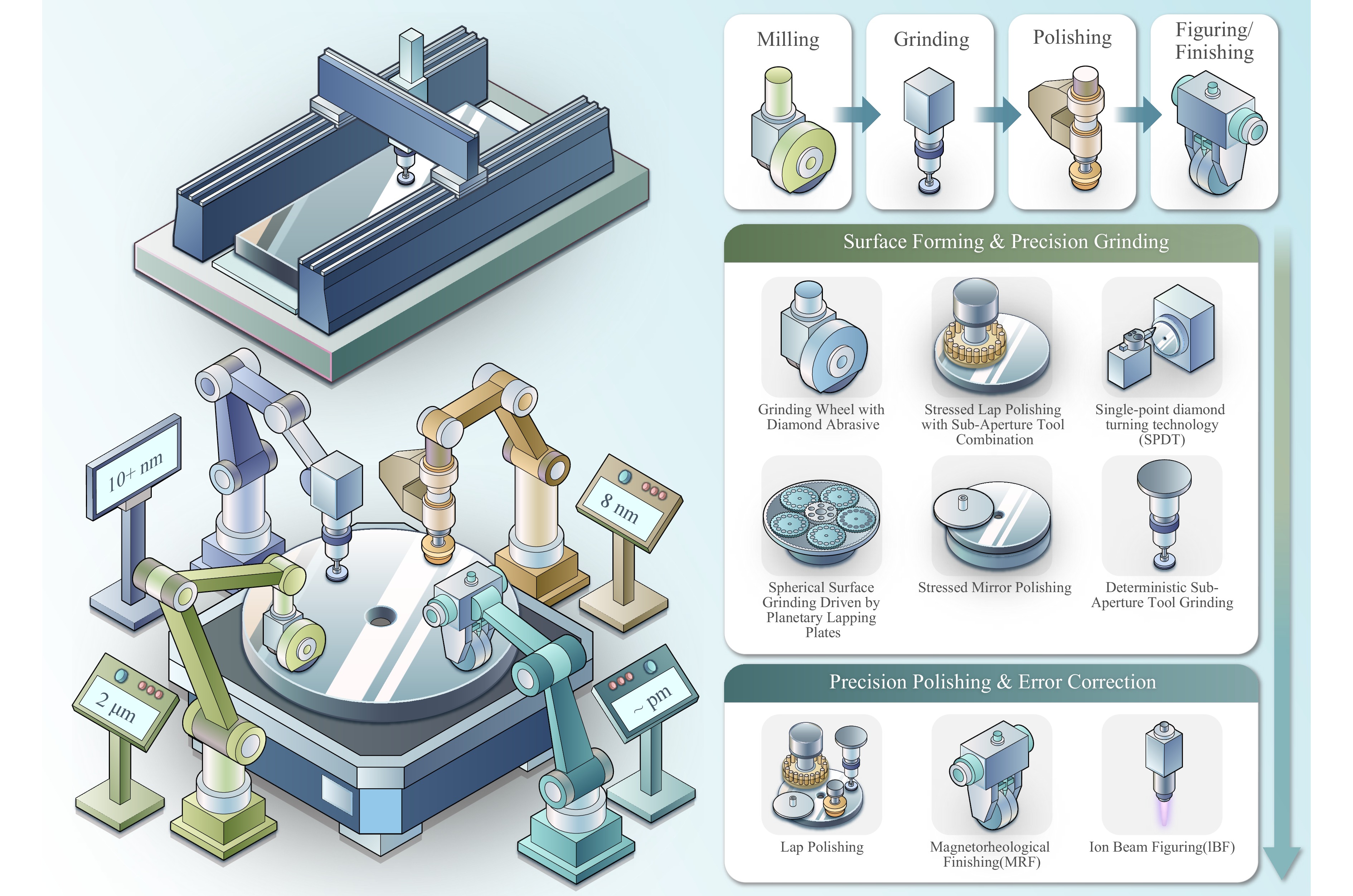
Fig. 3 Schematic overview of the integrated engineering chain for large-aperture optical mirror fabrication.
This section reviews the manufacturing routes of large-aperture optical mirrors from three perspectives. First, the basic mirror configurations, process routes, and key performance indicators are summarized. Second, the surface generation and rough grinding methods for monolithic and segmented mirrors are compared, with emphasis on fixed-abrasive and loose-abrasive processes. Third, precision polishing, and representative equipment systems are discussed. The purpose is to clarify how different technologies are selected and combined according to mirror material, aperture, surface form, spatial-frequency error, and system-level requirements.
-
Large-aperture optical mirror fabrication must balance optical performance, structural stability, manufacturability, and testing feasibility. Before discussing individual processes, it is necessary to clarify the main mirror architectures, typical manufacturing routes, and key indicators used to evaluate surface quality and system performance.
-
Large-aperture primary mirrors can be broadly classified into monolithic mirrors, segmented mirrors, and integrated multi-surface monolithic systems. Each configuration has distinct advantages and manufacturing challenges.
Monolithic mirrors provide a continuous optical surface and avoid segment phasing errors. However, the maximum aperture is constrained by blank fabrication, transportation, support deformation, thermal control, and full-aperture testing capability. Segmented mirrors overcome the aperture limit by combining multiple smaller elements, but they introduce additional requirements for segment-to-segment consistency, edge-effect control, active support, co-phasing, and system-level alignment. Integrated multi-surface monolithic systems, such as combined primary-tertiary mirrors, reduce alignment degrees of freedom by fabricating multiple optical surfaces on one substrate, but they require extremely demanding synchronous generation, polishing, and testing strategies. In summary, the choice of system is a trade-off between the fabrication limits of monolithic substrates, the phasing and control complexity of segmented designs, and the advanced manufacturing required for integrated multi-surface mirrors. The fundamental distinctions and trade-offs among these three architectures are visually summarized in Fig. 4.
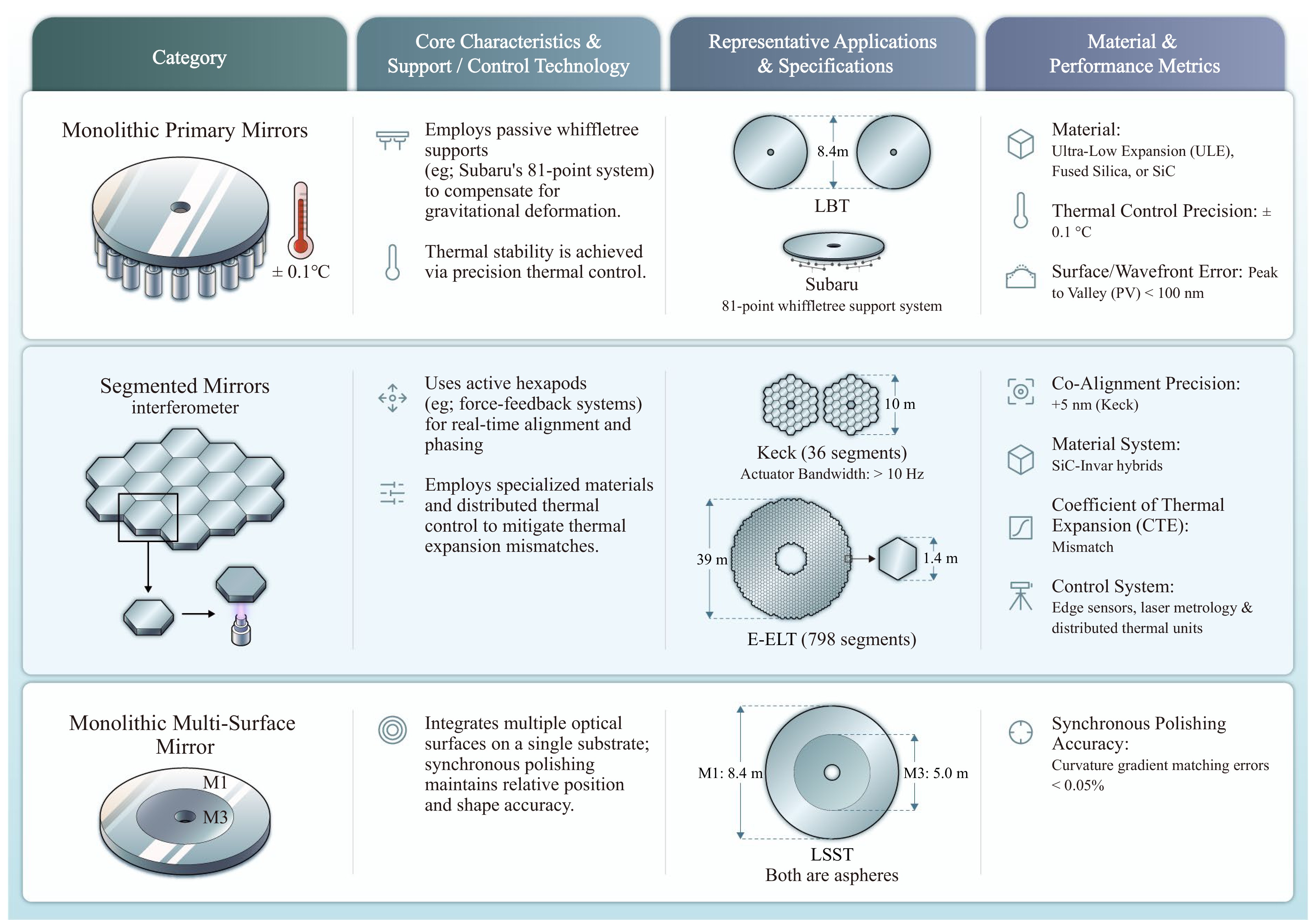
Fig. 4 Schematic comparison of three primary mirror architectures for large-aperture telescopes. The diagram contrasts the core concepts, support/control technologies, representative applications, and key specifications of monolithic7,26, segmented27,28, and multi-surface monolithic mirror systems29.
-
Although process details vary with mirror material, aperture, and surface prescription, the general route for large-aperture mirror fabrication follows a staged convergence strategy. Bulk material is first removed to obtain the approximate geometry; rough grinding then reduces form error and establishes a controlled residual stock; precision polishing subsequently converge the surface figure from micrometer-level errors to nanometer-level accuracy. Throughout the process, metrology feedback is essential for dwell-time calculation, error separation, and process correction.
For monolithic mirrors, the main objective is to obtain a continuous high-quality surface while controlling low-frequency figure error, mid-spatial-frequency error, roughness, and support-induced deformation. For segmented mirrors, the objective extends beyond the quality of each individual segment. The manufacturing chain must also ensure segment-to-segment consistency, controlled edge gradients, compatible mechanical interfaces, and sufficient margin for active alignment and co-phasing. The key distinctions between the manufacturing processes for monolithic and segmented mirrors are contrasted visually in Fig. 5, moving from a tabular to a schematic representation for enhanced clarity.
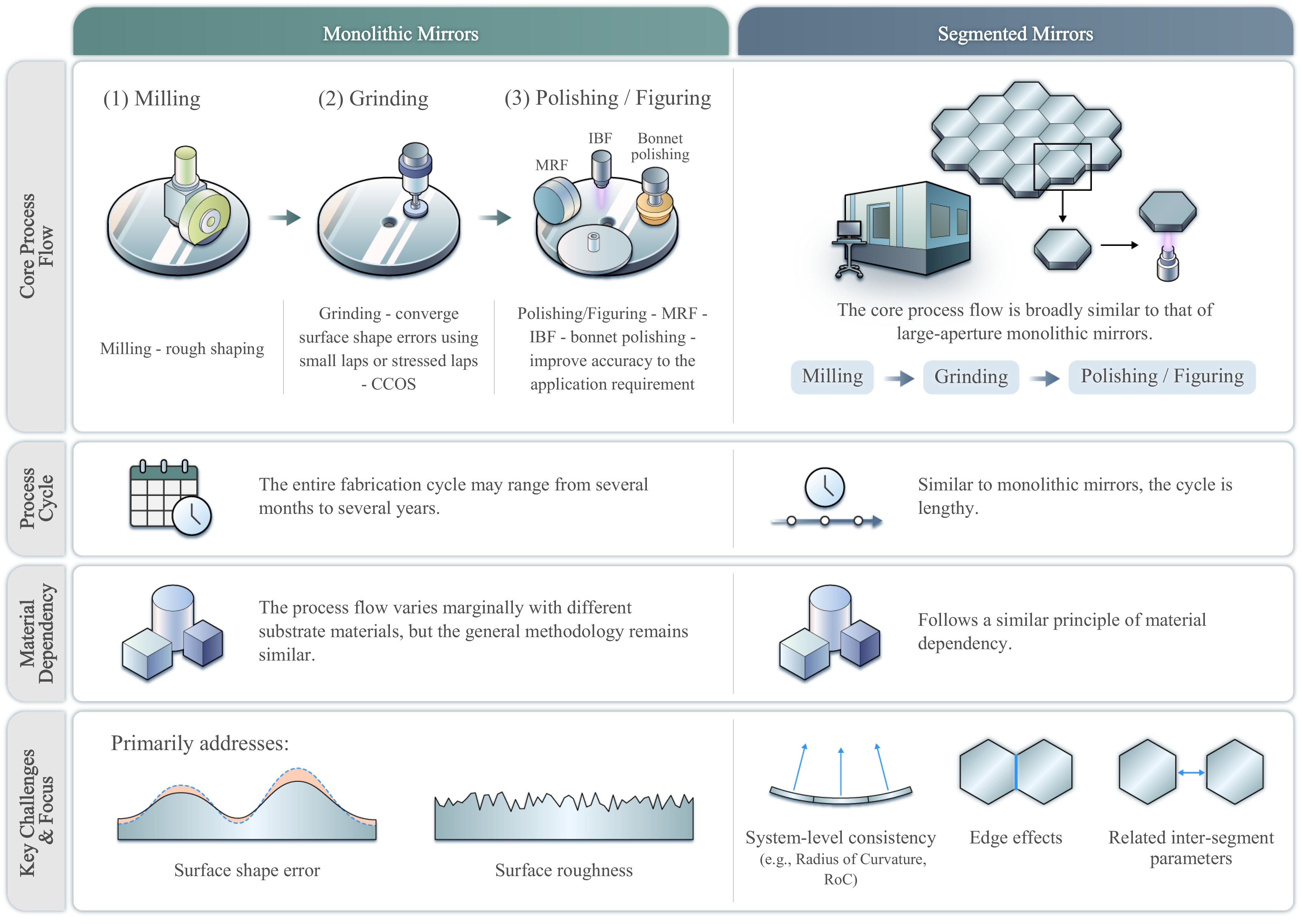
In contrast, the fabrication of segmented mirrors introduces an additional, critical layer of complexity: achieving system-level consistency. Beyond the quality of individual segments, manufacturers must ensure uniformity in parameters like the radius of curvature across all segments and manage edge effects and inter-segment relationships. This makes the process not just about creating excellent individual optical pieces, but about engineering them to function as a perfectly coherent single unit.
-
The performance of large-aperture optical mirrors is evaluated using a set of surface, structural, and system-level indicators. Surface figure error is usually described by PV and RMS values, while mid-spatial-frequency errors are commonly evaluated using PSD or band-limited RMS metrics. Surface roughness describes microscopic irregularities and is particularly important for controlling scatter, especially at short operating wavelengths. Subsurface damage is a hidden but critical factor introduced during grinding and must be removed or controlled before final polishing.
For segmented mirrors, additional indicators are required, including radius-of-curvature consistency, edge roll-off, segment clocking and indexing errors, actuator-interface accuracy, and residual co-phasing error. These indicators span surface, structural, and system-level attributes, with their definitions, metrics, and practical examples summarized in Table 2.
Core Indicator Description & Metrics Practical Data & Examples Surface Shape Accuracy Represents the overall deviation of the optical surface from the ideal shape5,39.
Total Error: Measured by PV and RMS.
Mid-frequency Errors: Controlled and evaluated using PSD40,41.Keck Primary Mirror: PV < 80 nm5;
E-ELT Sub-mirrors: RMS < 12 nm39.Surface Roughness Refers to microscopic irregularities on the surface22,41. measured at the nm scale. Other Considerations Application-specific parameters that are critical for performance. Subsurface Damage (SSD) Depth42;
Radius of Curvature Matching (RoC)21,43;
Segment Alignment & Phasing; Parameters44,45.Table 2. Key performance indicators for large-aperture reflecting mirrors
-
Surface generation and rough grinding form the foundation of the entire fabrication chain. At this stage, the main objectives are efficient material removal, reduction of gross figure error, control of residual stock, and suppression of subsurface damage. The selected process must match the substrate material, aperture, surface geometry, and expected spatial-frequency content of the residual error.
Two fundamental routes are commonly used: fixed-abrasive processing and loose-abrasive processing. Fixed-abrasive methods, such as diamond grinding, use bonded abrasive grains and are well suited for deterministic shaping of hard and brittle materials such as SiC, ceramics, and some glass-ceramics. Loose-abrasive methods rely on free abrasives between the tool and workpiece, and they are widely used for large glass mirrors, spherical segments, and stressed-lap processes where conformal contact and smoothing are required.
Fixed abrasive grinding emphasizes deterministic control over hard, brittle materials and precision freeform surfaces. During the rough generation stage, the primary goal is efficient near-net-shape formation and control of subsurface damage within a removable allowance. For example, the Herschel 3.5 m SiC mirror blank after diamond grinding exhibited a surface form error on the order of ~100 µm relative to the best-fit paraboloid. The subsequent polishing and figuring stages were designed to converge the figure to ~1.5 µm RMS, roughness to < 30 nm, and the final telescope wavefront error to < 6 µm RMS. The grinding-induced SSD layer (typically a few µm) was deliberately kept within the stock removal budget of the later processes20.
In loose abrasive grinding, the use of specially designed tools such as stressed laps and flexible laps provides strong smoothing capability and conformal contact, making this approach particularly suitable for ultra-large-scale aspheric and freeform optics. Representative techniques include stressed-lap grinding, which dynamically matches the tool curvature to the local surface shape for efficient material removal and low-frequency error convergence (e.g., the 8.4 m primary-tertiary mirror of LSST29), and flexible-lap grinding, which uses passively deformable tools to accommodate steep off-axis geometries (e.g., the 4.2 m off-axis primary mirror of DKIST46). These methods are especially effective for mirrors with steep curvature gradients, such as the 1:5 steepness ratio of the LSST primary mirror47, where conformal contact and smoothing are critical for controlling mid-spatial-frequency errors.
Fig. 6 provides a systematic comparison of the two fundamental grinding methods. The primary distinction lies in the material removal mechanism. Loose abrasive grinding is characterized by a stochastic process where free abrasives remove material primarily through brittle fracture caused by indentation and rolling. In contrast, fixed abrasive grinding employs a deterministic, geometrically constrained process where bonded grains remove material via a combination of micro-cutting, scratching, and fracture. This difference in removal is governed by the underlying tool-abrasive contact mechanism. This fundamental difference stems from the fact that these methods exhibit distinct tool-abrasive contact mechanisms. The contact in loose abrasive processes is transient and random, with very short durations, while in fixed abrasive processes, it is sustained, periodic, and defined by the tool's geometry and path. These differing mechanisms directly result in their unique material responses and make each method suitable for specific applications and materials in large-aperture mirror fabrication.
-
The surface forming and rough grinding of monolithic mirrors constitute a critical phase in achieving the desired optical prescription. This section details the primary manufacturing methodologies, beginning with fixed abrasive milling for initial material removal and contour shaping. It then explores loose abrasive grinding, with a specific focus on advanced techniques like stressed-lap grinding that actively control the tool's shape to correct for errors and efficiently converge the surface figure. Finally, a summary will be provided to compare these approaches and outline their respective roles in the fabrication workflow.
-
Fixed-abrasive generation is frequently used when the substrate is hard, brittle, or difficult to process using conventional loose-abrasive methods. Diamond grinding is the most representative process. Diamond abrasives embedded in a wheel or tool remove material through micro-cutting, frictional sliding, and ploughing. For brittle materials, the process may also induce median and lateral cracks; therefore, the control of grinding parameters is essential for limiting SSD and ensuring the efficiency and integrity of the subsequent manufacturing stages.
A representative example is the 3.5 m silicon carbide primary mirror of the Herschel Space Observatory52. Because SiC has high stiffness and thermal stability but also high hardness and brittleness, diamond grinding was adopted during rough generation. The process demonstrated high removal efficiency and controllable surface roughness, but also required careful management of edge-removal fluctuations, tool wear, and residual microcracks. These issues illustrate the central trade-off of fixed-abrasive grinding: it is efficient and deterministic, but must be integrated with subsequent fine grinding and polishing steps to remove or reduce SSD53,54.
-
Loose-abrasive grinding is widely used in large glass mirror fabrication because it provides strong smoothing capability and can be combined with large-area conformal tools. Among loose-abrasive methods, stressed-lap grinding is particularly important for large aspheric mirrors. As shown in Fig. 7 and Fig. 8, a stressed lap is an actively deformable tool whose curvature is adjusted to match the local curvature of the workpiece. This enables high material removal efficiency while maintaining conformal contact and suppressing mid-spatial-frequency errors55–58.
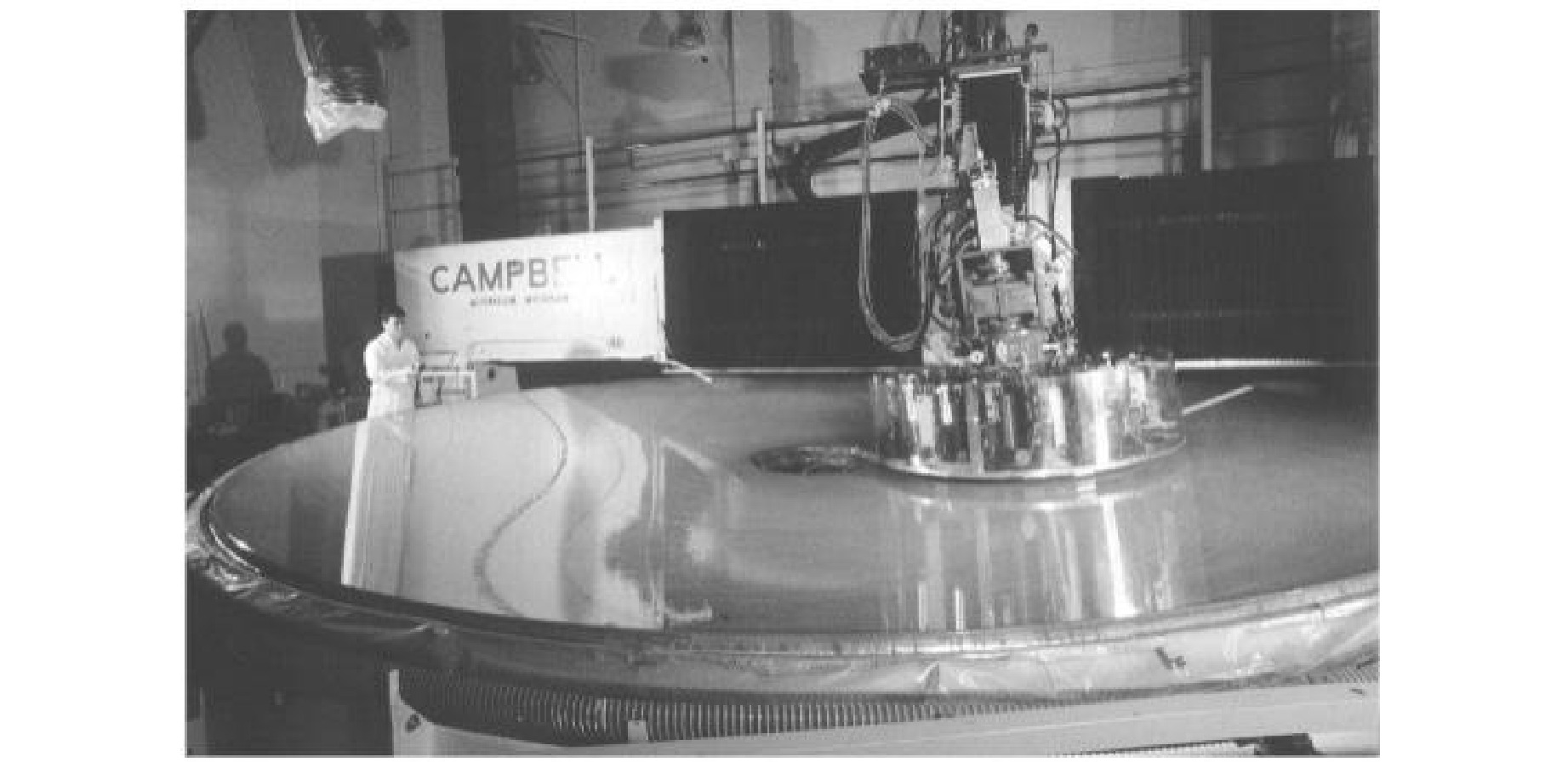
Fig. 7 Schematic of stressed-lap processing integrated with a large-scale CNC machine tool57.
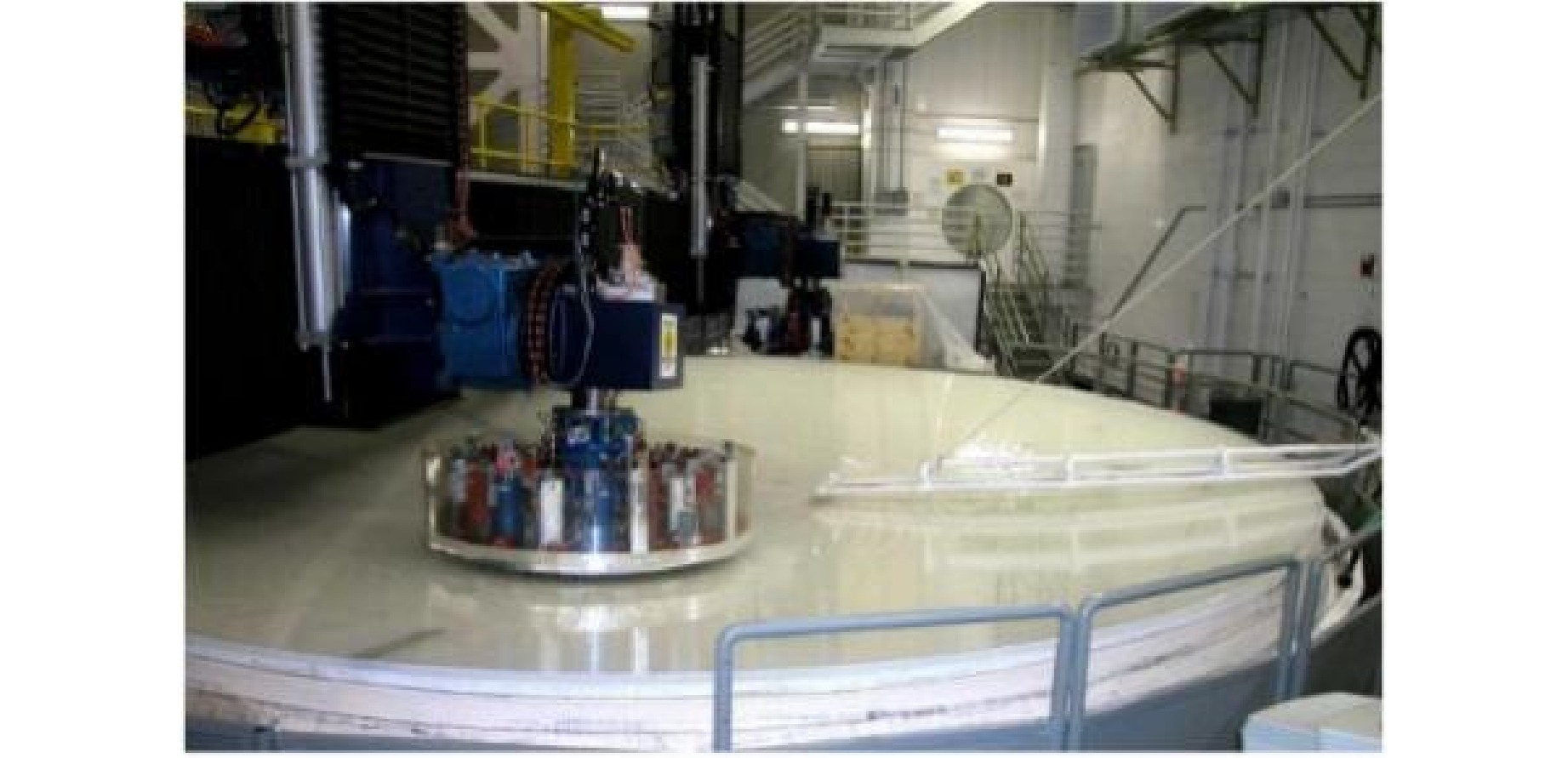
Fig. 8 Mirror Lab’s 8.4 m capacity large grinding machine. The photo shows two 1.2 m stressed laps60.
The Multiple Mirror Telescope (MMT) established an important technical basis for subsequent large honeycomb mirrors58. Its fabrication used large CNC generation combined with stressed-lap processing to converge the surface from millimeter-scale casting error toward micrometer-level accuracy. The stressed lap also provided passive smoothing, reducing mid-to-high spatial-frequency errors during rough and intermediate stages57,59.
The Rubin Observatory/LSST M1M3 mirror further illustrates the role of stressed-lap processing in complex monolithic systems. The combined primary-tertiary mirror requires coordinated shaping of two aspheric surfaces on a single substrate. Large stressed laps and smaller correction tools were used in combination to remove material efficiently while controlling the different curvature requirements of M1 and M347,60. Similarly, the off-axis primary mirror of DKIST used active and passive flexible laps to manage the combined challenges of off-axis geometry, large aperture, and high surface-quality requirements46,61.
-
For monolithic mirrors, rough generation must be selected according to material properties and surface geometry. Fixed-abrasive grinding provides efficient deterministic shaping for hard and brittle substrates, but requires strict SSD and tool-wear control. Loose-abrasive processes, particularly when combined with stressed-lap tools, are more suitable for large glass mirrors and steep aspheres because they provide conformal contact, smoothing, and efficient convergence of low- and mid-frequency errors. In practice, high-precision fabrication of large-aperture mirrors often combine these routes to balance material removal rate, damage control, and subsequent polishing efficiency.
To facilitate the selection of rough grinding technologies, Table 3 summarizes the key features, applicable materials, representative applications, and challenges of major methods. In conclusion, the selection of a rough grinding technology involves a fundamental trade-off between efficiency, precision, and damage control. No single technology is universally superior. The success of modern large-scale projects (such as Herschel, LSST, and DKIST) hinges on selecting or hybridizing the most appropriate rough grinding strategy based on specific material properties, surface form requirements, and production timelines. This strategic choice is crucial for ensuring that the process provides sufficient and predictable material allowance for the subsequent fine grinding and polishing stages to achieve the final nanometer-level accuracy.
Feature Fixed Abrasive Milling (Diamond Grinding) Loose Abrasive Grinding (Stressed-Lap) Loose Abrasive Grinding (Flexible Lap) Category Fixed Abrasive Milling62 Loose Abrasive Grinding63 Loose Abrasive Grinding64 Technology Diamond Grinding. Stressed-Lap Grinding65 FLEX Lap Grinding Principle Material removal via micro-cutting, frictional sliding, and ploughing using diamond-embedded grinding wheels66 Achieves conformal contact using a controllably deformable lap, based on Hertzian contact theory and active optics67 Material removal via random collisions and scratching by free abrasives using multi-size flexible laps68 Key Characteristics High material removal rate (MRR). Effective for hard/brittle materials;
Brittle-fracture-dominated removalHigh adaptability to aspheric surfaces. High-efficiency material removal (> 90%).
Synchronous multi-scale error control69Precise material removal. Suitable for complex off-axis surfaces. Enables synergy between rough and fine grinding Applicable Materials Cemented carbides, Ceramics, Optical glasses, Sapphire, Semiconductor wafers, Polycrystalline diamond Optical glass substrates (e.g., borosilicate, ULE). SiC mirrors > 4 m. Steep aspheres (ratio >1:10) Large off-axis aspheric mirrors Representative Applications Herschel Space Observatory: 3.5 m SiC
primary mirror54LSST: 8.4 m primary-tertiary mirror60 DKIST: 4.2 m off-axis primary mirror (coarse & fine grinding)46 Challenges & Notes Fluctuating MRR at edges;
Micro-crack formation;
Significant grinding wheel wear;
Requires balancing efficiency with SSD controlHighly dependent on high-precision motion systems and real-time deformation control algorithms Requires computer-controlled multi-axis systems and optimized abrasive grit sizes56 Table 3. Summary of rough grinding technologies for large optical mirrors
-
Segmented mirror fabrication addresses the manufacturing of extremely large-aperture optical systems by combining multiple mirror segments. The process employs two primary technological pathways: fixed abrasive milling for efficient material removal and deterministic shaping of individual segments, and loose abrasive grinding, which encompasses several advanced methods. These include spherical surface grinding driven by planetary lapping plates for uniform stock removal, stressed-lap grinding for conformal aspheric shaping, stressed mirror polishing for precise figure correction by actively bending the mirror, and deterministic sub-aperture tool grinding for controlling mid-to-high spatial frequency errors. This suite of techniques ensures that each segment achieves the required surface figure and quality while meeting the critical co-phasing requirements for the final assembled mirror.
-
Segmented mirrors require not only accurate surface generation of each segment, but also strict control of thickness, edge geometry, support interfaces, and segment-to-segment consistency. Fixed-abrasive milling and diamond grinding are therefore used when deterministic shaping and high removal efficiency are required. For off-axis aspheric segments, such as those used in the GMT9, computer-controlled generation provides the initial off-axis geometry and reduces the burden on subsequent stressed-lap polishing and local figuring.
-
For segmented mirrors with spherical or near-spherical prescriptions, as shown in Fig. 9, planetary lapping and loose-abrasive grinding provide efficient and repeatable processing routes. HET70, SALT71, and LAMOST72 illustrate this approach. By matching the curvature of the tool and segment surface, planetary grinding can provide stable material removal and good surface smoothing for large batches of spherical segments.
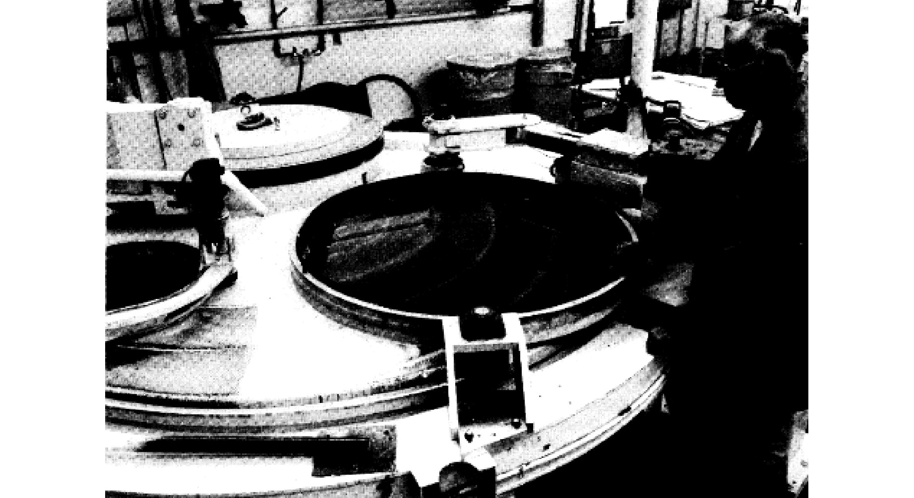
Fig. 9 Planetary polishing machine70.
For off-axis or strongly aspheric segments, more advanced strategies are required. Stressed-lap grinding uses a deformable tool to maintain conformal contact with each segment, while stressed-mirror polishing deforms the segment itself into a more easily polished shape. After unloading, elastic spring-back produces the target aspheric figure. This principle was used in the fabrication of Keck segments and has also been studied for next-generation segmented telescopes5,73. Deterministic sub-aperture grinding and small-lap correction complement large-tool methods. Large tools are efficient for low-frequency and global errors, whereas small tools can correct edge roll-off, mid-frequency waviness, and local residual errors. A hierarchical tool chain, combining large stressed laps, rigid conformal tools, and smaller correction tools, is therefore essential for segmented mirror fabrication.
-
Compared with monolithic mirrors, segmented mirror fabrication places stronger emphasis on batch consistency, edge control, and system-level compatibility. Each segment must meet individual surface specifications while also preserving geometric correlations with the full primary mirror. Effective rough-generation strategies therefore combine multi-scale tooling, elastic deformation models, process-specific SSD control, and metrology-guided error separation.
In conclusion, as summarized in Table 4, the grinding of segmented mirrors necessitates integrated solutions that combine multi-tool strategies (e.g., stressed laps for global errors and sub-aperture tools for mid-to-high frequency correction), cross-scale error decoupling, and material-specific process optimization. These approaches ensure uniform subsurface integrity and controlled residual stock for the subsequent polishing stage.
Category Specific Challenge Core Technical Approach Representative Project Key Technical Indicator Major Challenges Non-continuous surface shape convergence Pre-deformation of segments
to a machinable shapeKeck Telescope: Pre-deformation stress disk technology using asymmetric force fields74 Decomposed global asphere into locally spherical base (6.8 mm compensation) Major Challenges Edge collapse compensation Dynamic adjustment of pressure distribution at edges GMT: Combined 1.5 m stressed lap with 40 cm passive grinding lap75 Effectively suppressed edge collapse during rough grinding Major Challenges Cross-scale error coupling Isolating and correcting errors at different spatial frequencies HET: Planetary grinders (Φ2.5 m) combined with cylindrical grinders76 Isolated full-aperture low-frequency from mid-frequency errors in splice region Sub-mirror Geometric Correlation Control Aspheric Surface Decomposition Pre-deformation via elastic mechanics modeling Keck Telescope69 Achieved locally machinable spherical surface Sub-mirror Geometric Correlation Control Edge Effect Mitigation Multi-size tooling for tailored pressure distribution GMT Project77 Controlled material removal rate at critical edges Dynamic Error Decoupling Strategy Multi-scale Error Separation Synergistic use of large and small tools in a toolchain HET Project: Planetary grinder + cylindrical grinder + small-lap process70 Removed 90% material with loose abrasives; corrected residual high-frequency errors Dynamic Error Decoupling Strategy Heterogeneous Material Processing Corrected contact model for
non-uniform substratesMMT Project: Hertzian contact model with equivalent elastic modulus correction (1.12−1.18)78 Reduced removal rate discrepancy from 15% to < 8% Surface Forming Accuracy Guarantee Surface & Sub-surface Quality Control Gradient abrasive process (multi-grit sizes) SDSS Project: 40 μm Al2O3 + 9μm diamond composite abrasives79 Simultaneously achieved Ra < 0.5 μm and SSD < 18 μm Surface Forming Accuracy Guarantee In-situ Metrology & Correction Dynamic path correction based
on regular error mapping72LAMOST System: Laser tracker + contact profilometer feedback Converged gradient error in spliced area to 0.3 μm/mm Conclusion Integrated Solution Combines multi-tool strategies70, cross-scale error decoupling76, and material-specific optimization78 General Approach Ensures uniform subsurface integrity and controlled residual stock for polishing Table 4. Coarse grinding of segmented mirrors
-
Precision polishing converts the surface produced by grinding into an optical-quality mirror. Modern large-aperture polishing is usually based on computer-controlled optical surfacing. The removal distribution is calculated from measured surface error, a calibrated removal function, and a dwell-time algorithm. The process is therefore deterministic, metrology-driven, and iterative.
Different technologies operate most effectively over different spatial-frequency ranges. Large stressed laps and compliant tools are efficient for low-frequency and large-scale errors; small tools and MRF are effective for mid-spatial-frequency and local errors; IBF provides non-contact final figuring and is especially useful when residual error must be corrected without introducing mechanical stress.
-
The manufacture of monolithic large-diameter optical elements presents significant challenges, including extremely high demands on process stability, high scrap rates, prolonged grinding and polishing durations, difficulties in managing gravity-induced deformation and mechanical support, and limitations in full-aperture testing equipment. In response to these challenges, numerous advanced polishing technologies have been developed, as detailed in the following subsections.
-
Stressed-lap polishing (SLP) is a key technology for large aspheric monolithic mirrors. By actively adjusting the shape of a deformable lap, SLP maintains near-conformal contact with the mirror surface. This enables relatively high removal rates while providing smoothing and low-frequency figure convergence.
In practice, SLP is often used in combination with smaller sub-aperture tools. The large stressed lap removes broad, low-frequency errors and maintains global smoothness, while small tools correct localized residual errors, edge zones, and mid-spatial-frequency features. The multi-tool combination machining of the LSST project is shown in Fig. 10, the machining overview of the SOAR project is shown in Fig. 11, and the polishing lap machining of the LBT project is shown in Fig. 12. This multi-tool strategy has been applied in the fabrication of large telescope mirrors such as LSST/Rubin M1M347,60,80, SOAR7,12,81, LBT14,26,57,82, Subaru7,12, and other 8 m-class systems.
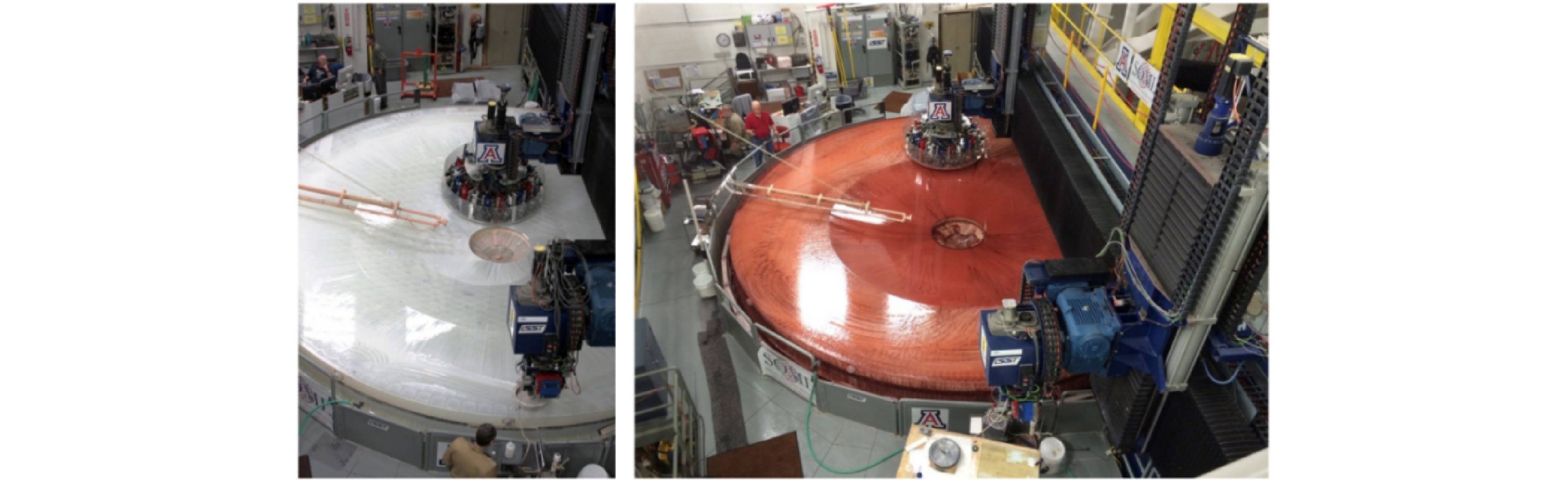
Fig. 10 Two views of the combined LSST M1 and M3 being polished. Left: 1.2 m stressed lap on M3 and 25 cm orbital lap on M1, with zirconium oxide polishing compound. Right: stressed lap polishing M1 with rouge (iron oxide)80.
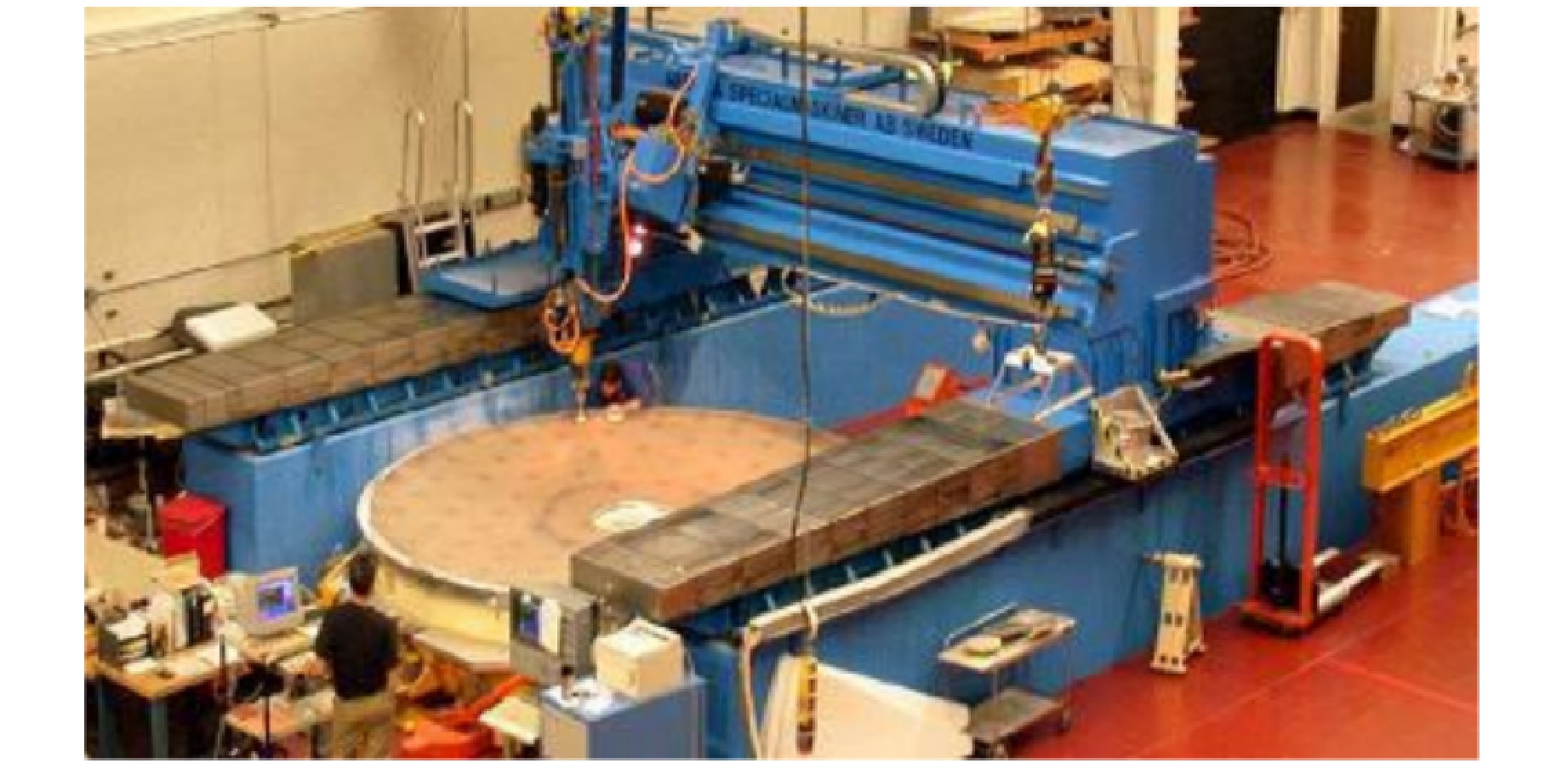
Fig. 11 Primary mirror being optically fabricated using Goodrich’s large computer-controlled grinding and polishing machine12.
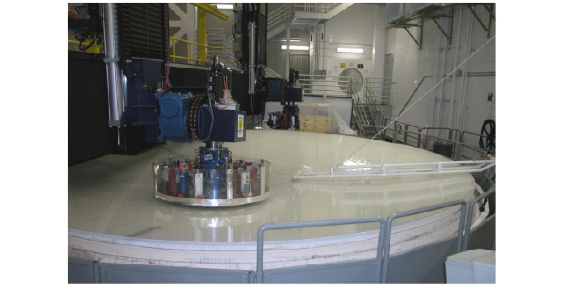
Fig. 12 Stressed-lap polishing of the second LBT mirror on the new 8.4 m polisher82.
The main advantages of SLP are high material removal efficiency, curvature adaptability, and effective control of large-scale figure errors. Its limitations include actuator bandwidth, calibration of lap deformation, wear of polishing layers, thermal-mechanical coupling, and the need for accurate dwell-time planning. The specific advantages and inherent challenges of this technology are further detailed in Table 5.
Advantages Challenges Dynamic curvature matching enables high-precision surface shape control14,82. Limited response bandwidth of large actuators restricts dynamic adjustment speed. Rigid-flexible composite tool design achieves material removal rates
> 10 μm/h60.Complex asphalt/ceramic layer wear requires calibration and maintenance every 48 hours80. Multi-tool collaborative control supports error separation efficiency > 80%47. Modeling thermo-mechanical coupling in steep asphere processing is challenging, affecting stability57. Table 5. Advantages and challenges of stressed-Lap polishing technology
Together, these advantages and challenges define the current state of stressed-lap polishing technology in large-aperture optical fabrication.
-
Magnetorheological finishing uses a magnetically stiffened polishing fluid to form a controllable, flexible removal zone. Under a magnetic field, the magnetorheological fluid develops a localized yield stress and behaves like a compliant polishing tool. The removal function is typically stable and deterministic, making MRF effective for correcting mid- and high-spatial-frequency errors83–87.
MRF has been applied to a wide range of optical components, including off-axis aspheres and large SiC mirrors. As shown in Figs. 13−16, reported cases include 1.5 m-class off-axis aspheric mirrors84,88,89, 2 m SiC mirrors89,90, and the 4.03 m SiC mirror developed by CIOMP22,24,91. These demonstrations show that MRF can significantly improve figure accuracy and reduce residual errors after conventional polishing.
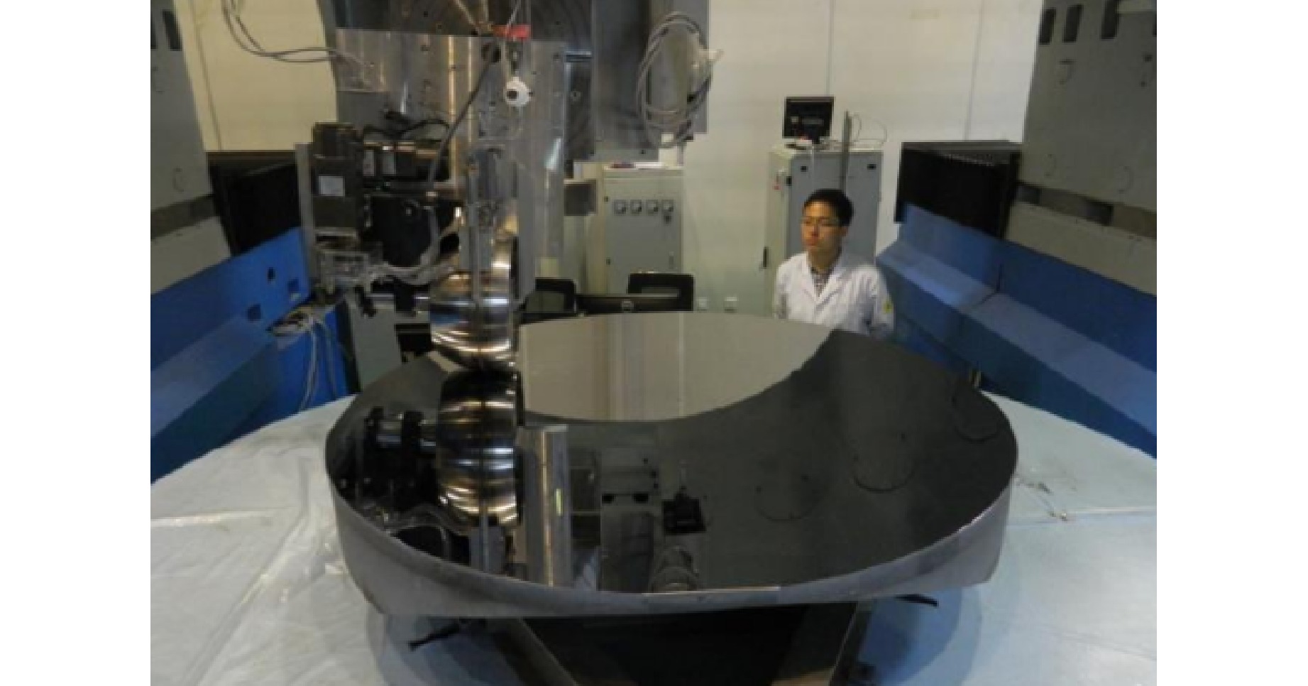
Fig. 13 MRF process84.
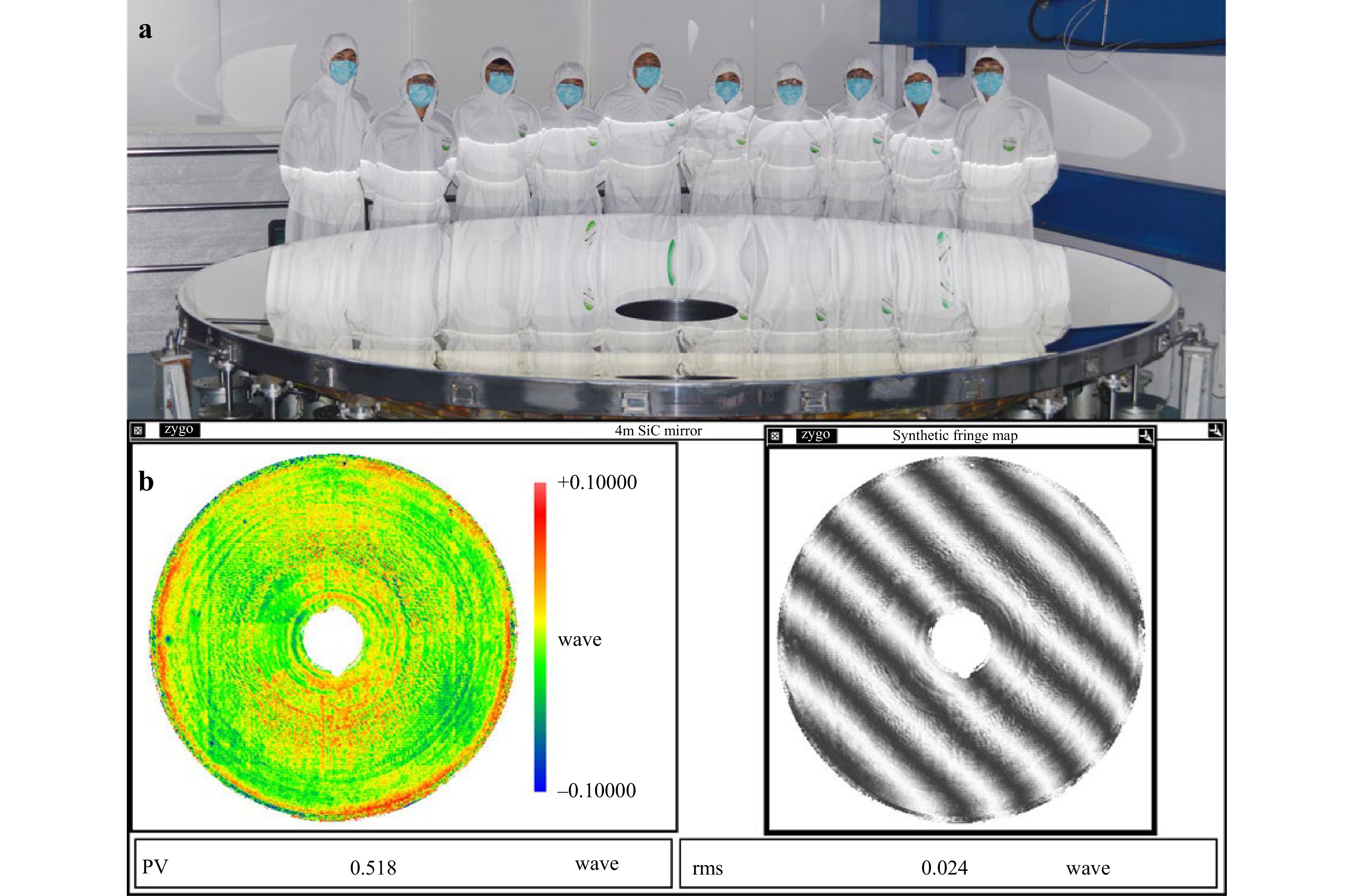
Fig. 16 a Photograph of the world’s largest $\varnothing $4.03 m SiC aspheric mirror. b Test result and interferogram of the $\varnothing $4 m SiC mirror22.
The main strengths of MRF are deterministic convergence, low mechanical loading, good local correction capability, and suitability for complex aspheres. Its main limitations are relatively low removal efficiency for very large apertures, sensitivity to removal-function stability, slurry management, and the need to integrate MRF with upstream smoothing and downstream final testing.
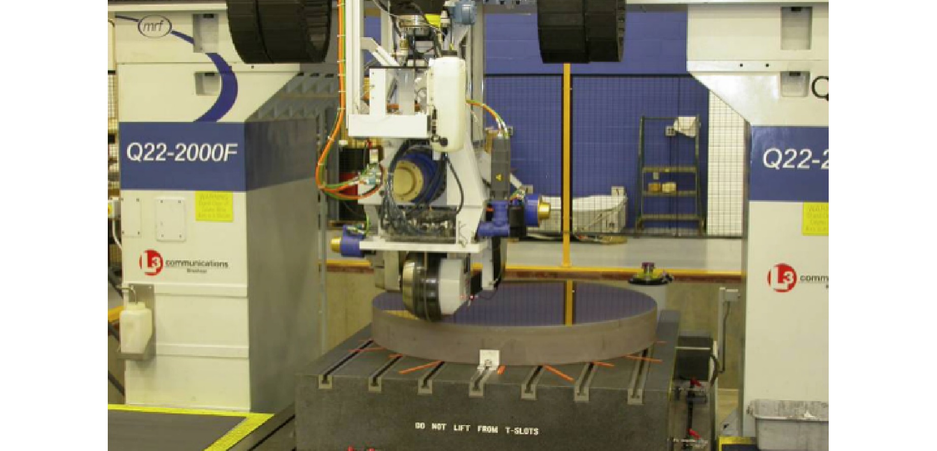
Fig. 14 Q22-2000F MRF polishing machine, commissioned in July 2008, used for 1.5 m diameter optics89.
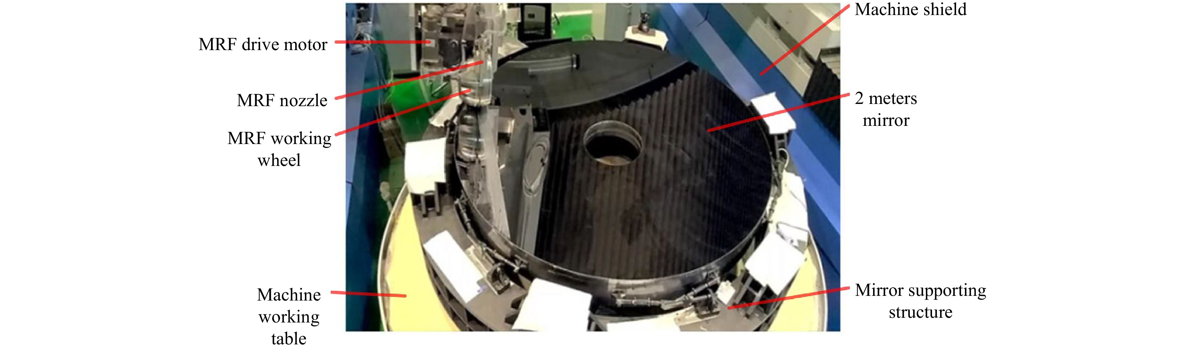
Fig. 15 2 m SiC mirror after polishing90.
MRF establishes itself as a pivotal technology in modern optics manufacturing. Its capacity for deterministic error correction and subsurface damage elimination enables the production of high-precision surfaces with rapid convergence. However, the technology's full potential in production environments remains contingent upon overcoming key challenges, particularly in enhancing removal efficiency, improving process repeatability, and scaling for broader industrial implementation.
The MRF technology is experiencing rapid development. In recent years, its processing strategies92, equipment93, mechanisms94,95, processes96,97, prediction models98,99, paths100, etc. have been extensively studied.
-
Ion beam figuring is a non-contact deterministic figuring process based on atomic-scale sputtering. Inert gas ions are accelerated and directed toward the optical surface, removing material through momentum transfer. Because the process is contactless, IBF does not introduce mechanical stress, tool marks, or additional subsurface damage. It is therefore often used as a final figuring step after mechanical polishing44,45,101.
IBF is particularly suitable for correcting residual figure errors on high-precision aspheric surfaces and segmented mirrors. For example, as shown in Fig. 17, it has been used in the final correction of large telescope components such as the LSST/Rubin secondary mirror and mirror segments for segmented telescopes. Its main challenges are relatively low material removal rate, high equipment cost, the need for a vacuum chamber, and possible thermal effects induced by localized beam energy102.
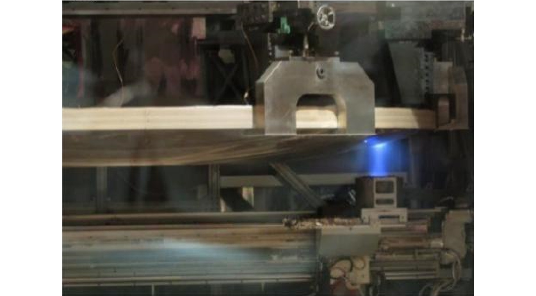
Fig. 17 Device developed by Harris Corporation102.
-
For monolithic mirrors, SLP, MRF, and IBF form a complementary process chain. SLP provides efficient large-scale convergence; MRF corrects local and mid-spatial-frequency residuals with high determinism; and IBF provides non-contact final correction at nanometer or sub-nanometer scale. The optimal process route is usually hybrid rather than single-technology based.
-
When polishing segmented mirrors, the manufacturing objective shifts from producing a single continuous surface to producing many mutually consistent segments. Each segment must meet its own surface figure and roughness specifications, but it must also satisfy system-level requirements for edge quality, radius of curvature, actuator interfaces, and co-phasing.
Small-lap CCOS is widely used for segment polishing because segment dimensions are smaller than monolithic mirrors and local correction is often efficient. For LAMOST segments72,103, deterministic small-tool polishing combined with interferometric feedback enabled high-accuracy spherical segment fabrication. For Keck5,73,74,104, GMT105,106, and other segmented systems, small tools complement stressed-lap or stressed-mirror processes by correcting residual local errors and edge zones.
-
As shown in Fig. 18, stressed-lap polishing remains important for large off-axis or aspheric segments because it provides efficient low-frequency convergence. Stressed-mirror polishing provides another route: the segment is elastically deformed into a more easily polished shape and then released to obtain the target aspheric surface. This strategy can be efficient for thin or flexible segments, but it requires accurate elastic modeling, precise loading, and careful edge compensation.
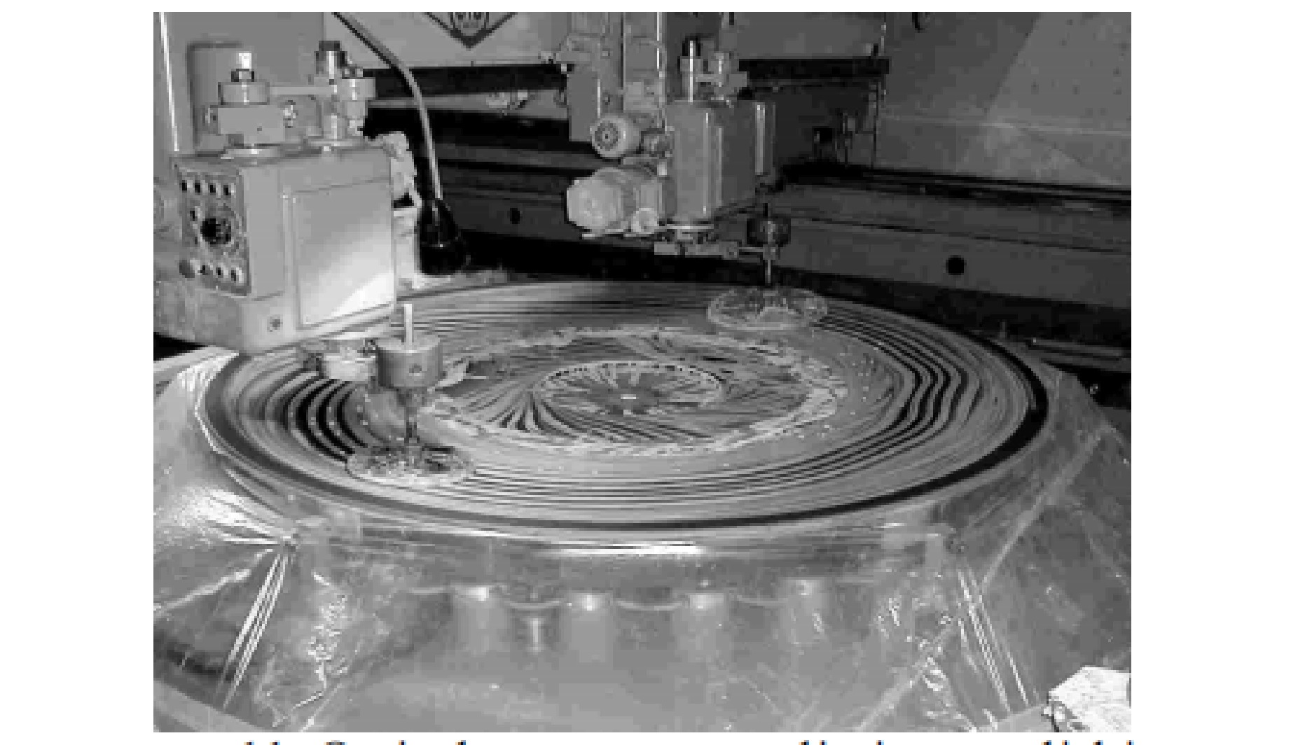
Fig. 18 Optical component preliminary polishing72.
As shown in Fig. 19, small-lap polishing and deterministic CCOS are essential for final correction of segment-level residuals. By combining tool-size selection, dwell-time optimization, and boundary-control strategies, small tools can suppress mid-frequency error, edge roll-off, and local ripple. The resulting process chain is usually hierarchical: large tools handle global figure, intermediate tools handle regional errors, and small tools handle local residuals.
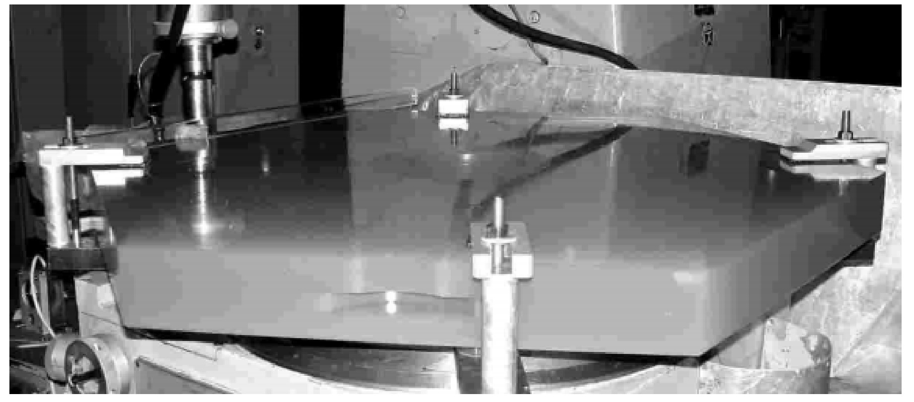
Fig. 19 LAMOST sub-mirror milling72.
-
IBF is particularly valuable for segmented mirrors because it can correct residual errors near edges without mechanical contact. As shown in Figs. 20−22, the process has been reported in the fabrication or final figuring of segments for telescopes such as GTC107,108, Keck-related segment development5,27,73,74, ELT15,36,109-111, and other large segmented systems. Its ability to perform non-contact local correction makes it suitable for high-accuracy edge zones and final figure correction.
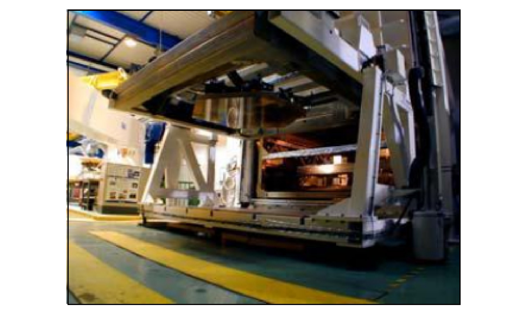
Fig. 20 GTC primary mirror undergoing ion beam shaping108.
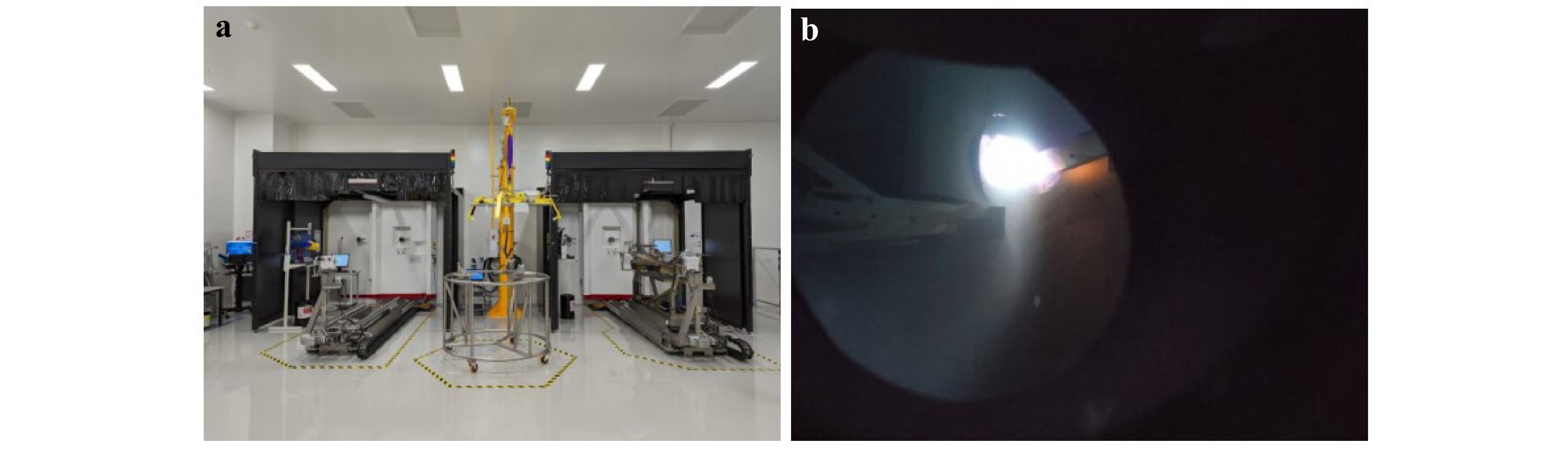
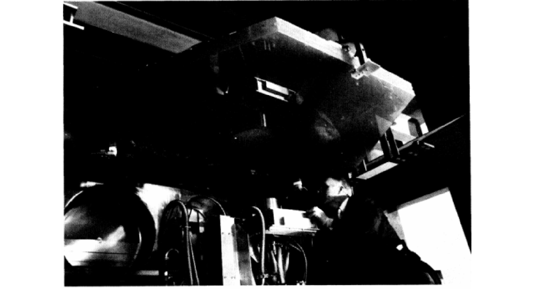
Fig. 21 Keck PM segment supported in a 2.5 m ion figuring system using a three-pad support fixture5.
The main engineering constraints of IBF are chamber size, throughput, thermal management, and cost. For mass production of hundreds of mirror segments, these constraints require careful process scheduling, standardized fixtures, stable removal-function calibration, and efficient metrology feedback.
-
Single-point diamond turning is an ultra-precision machining technology especially suitable for metallic mirrors and selected infrared optical components. It can generate optical surfaces with high geometric accuracy and low roughness on materials such as aluminum alloys and some beryllium-based substrates. In space optics, SPDT is attractive because it can combine lightweight metal substrates with deterministic machining.
It should be noted that SPDT is fundamentally different from conventional optical polishing methods. It is not a routine surface smoothing technique, but rather a precision machining process. Therefore, SPDT is typically reserved for specific applications requiring the fabrication of specialized infrared optical components or those made of special materials, rather than for the final figuring of general large-aperture reflective mirrors.
As shown in Fig. 23, the Ariel telescope mirror development provides a representative example of aluminum mirror fabrication using SPDT. Prototype mirrors demonstrated that diamond turning can achieve sub-micrometer figure accuracy and nanometer-level roughness on aluminum substrates. Nevertheless, tool wear, cutting-force variation, material anisotropy, and residual turning marks remain important challenges for large mirrors and batch production. For beryllium mirrors, SPDT is relevant as a manufacturing possibility, but any project-specific claim should be supported by primary manufacturing documentation112–115.
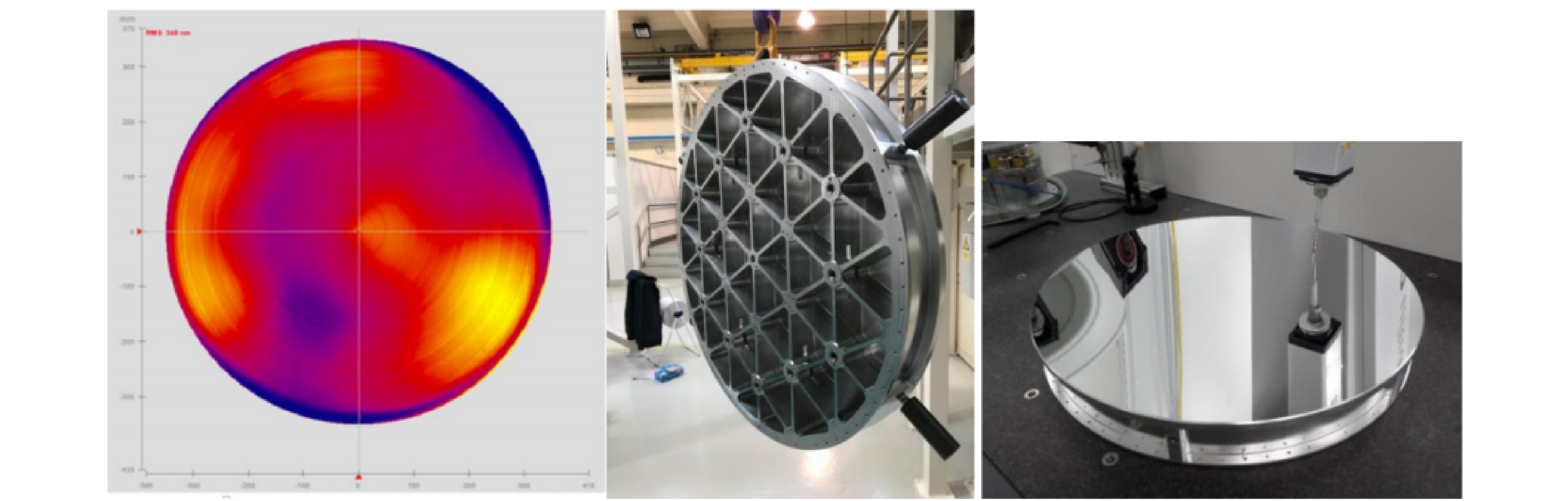
Fig. 23 Prototype mirror after diamond turning112.
-
For segmented mirrors, polishing and figuring technologies must support both optical precision and system integration. Stressed-lap and stressed-mirror processes provide efficient low-frequency correction; small-lap CCOS offers flexible local correction; MRF provides deterministic mid-frequency error control; IBF enables non-contact final figuring; and SPDT is useful for selected metal-mirror applications. Future development will focus on production repeatability, edge control, automated metrology feedback, and cross-scale error management for hundreds of segments.
-
Large-aperture optical fabrication depends on specialized equipment systems. These systems must provide not only sufficient mechanical range and stiffness, but also high thermal stability, controllable tool pressure, precise trajectory execution, and compatibility with in-process or off-line metrology. Equipment development has therefore become a central part of large mirror manufacturing capability.
The major equipment categories include ultra-precision CNC generation machines, large polishing machines, deterministic figuring systems, robotic polishing systems, and large-scale testing-compatible support platforms. These systems are increasingly integrated with digital process planning and closed-loop metrology.
-
Ultra-precision CNC machines and large optical generators are used for initial surface generation, backside machining, lightweight mechanical fixture support preparation, and deterministic grinding. Their performance depends on multi-axis motion accuracy, dynamic stiffness, thermal stability, tool-path planning, and error compensation. In large mirror fabrication, absolute positioning accuracy is important, but stable and repeatable dwell-time or tool-path execution is often more critical for deterministic material removal.
For off-axis or freeform segments, CNC machines must control tool orientation, contact pressure, and local removal while avoiding edge damage and excessive SSD. Future development will continue to emphasize machine thermal control, dynamic-error compensation, and integration with measured surface maps.
In practice, many dedicated polishing systems are built upon ultra-precision CNC platforms. Dedicated polishing equipment is designed for specific process requirements in large-aperture mirror fabrication. Examples include large polishing machines with dual heads (Fig. 24), stressed-lap systems (Fig. 25), large optical generators (Fig. 25), and large IBF chambers (Fig. 26). These systems are often developed in close connection with particular telescope projects and then become enabling platforms for subsequent mirrors.

Fig. 24 Dual-head LPM75.
As shown in the Table 6. The University of Arizona large polishing machines demonstrate the value of multi-tool coordination, combining large stressed laps for rapid convergence with smaller tools for local correction. Large optical generators provide the deterministic shaping capability needed for large off-axis segments such as those used in GMT. Large-scale IBF systems provide non-contact final figuring for high-precision segmented mirrors, although chamber size and throughput remain major constraints.
Manufacturing unit Dedicated polishing equipment Processing project Specific circumstances University of Arizona Large optical generator LBT Secondary main mirror (8.4 m); used for fine grinding to final dimensions. LSST Main mirror (8.4 m); part of the dual-head LPM, supporting stressed disk and sub-aperture tool operation. GMT Off-axis lens section (8.4 m); completed surface generation and fine grinding of segments S2, S3, and S5. SAGEM-REOSC IBF GTC Primary mirror (10.4 m, composite); final surface correction of 36 hexagonal sub-mirrors. GTC Secondary mirror (M2, 1.18 m); final shaping after high-precision aspheric polishing. University of Arizona Dual-head LPM LSST Simultaneous processing of concentric main mirror (RC rigid disk) and tertiary mirror (1.2 m stressed lap). GMT Off-axis segment (8.4 m); dual-tool coordinated shaping (e.g., 1.2 m stressed lap + 27 cm RC flexible disk) for tertiary mirror segment. LBT Basic equipment prototype supporting dual stressed laps or stressed lap/local shaping tool combinations. Table 6. Dedicated polishing equipment processing project information form
-
Robotic polishing systems provide flexible multi-degree-of-freedom motion and are well suited for complex surfaces, large lightweight mirrors, and components that require adaptive tool orientation. A robotic platform can combine force-position control, compliant tools, and adaptive path planning to maintain stable contact between tool and workpiece.
Compared with traditional fixed-machine polishing, robotic systems offer greater accessibility and flexibility, particularly for sub-aperture processing on strongly curved or highly aspheric zones; however, they face characteristic challenges in stiffness, dynamic accuracy, force stability, vibration suppression, and calibration. Therefore, robotic polishing is most effective when combined with accurate removal-function characterization, robust force control, and frequent metrology feedback—and when its role is clearly positioned within an overall deterministic fabrication chain.
Currently, robotic polishing technology has established mature solutions for processing mirrors with diameters ranging from 1 to 2 meters. Such systems typically employ industrial robots or dedicated manipulators equipped with small polishing tools, achieving stable contact through hybrid force–position control and performing dwell-time compensation based on iterative measurements of surface figure errors and geometric deviations obtained during the process. Typical process configurations include small-tool polishing118, bonnet polishing119, and magnetorheological finishing (MRF)120, each of which can be integrated onto a robotic platform to accommodate different curvatures and materials.
In engineering practice, several institutions have applied robotic polishing to the batch production of medium-aperture mirrors. For instance, the Changchun Institute of Optics, Fine Mechanics and Physics (CIOMP) developed a robotic MRF system for 1-meter-class aspheric mirrors, achieving nanometer-level convergence in figure correction22,121. During the fabrication of the ELT secondary mirror (4.25 m diameter), SAGEM-REOSC also employed a dual-head robotic polishing station to accelerate material removal in the rough-polishing stage122, although the final figure was still completed using conventional small tools and ion beam figuring. These examples indicate that robotic polishing currently serves mainly the 1–2 m aperture range and is particularly suitable for the serialized and automated production of segmented mirror subunits.
Looking ahead, the trend in robotic polishing lies in higher levels of automation and integration. As demand grows for ultra-large-aperture mirrors (≥ 4 m), a single robot becomes insufficient to cover the entire working surface, making multi-robot collaborative processing a potential technical direction. Through coordinated multi-arm motion, distributed force control, and global figure feedback, it is expected to achieve higher error-correction efficiency and more uniform material removal on large workpieces, thereby shortening the overall manufacturing cycle.
-
The manufacturing equipment system for large-aperture optical mirrors is evolving from isolated processing machines toward integrated closed-loop manufacturing platforms. Future systems will increasingly combine deterministic removal models, in-process sensing, surface-map-driven dwell-time optimization, environmental control, and data-based process compensation. The interplay among these core technological pillars—ranging from ultra-precision machines to system integration—and their associated trends are synthesized in Fig. 27, which moves beyond a tabular listing to provide a schematic overview of the current technological landscape and its future trajectory. Digital twins and artificial-intelligence-based planning may become useful tools, but their roles should be described as emerging trends unless supported by validated engineering demonstrations.
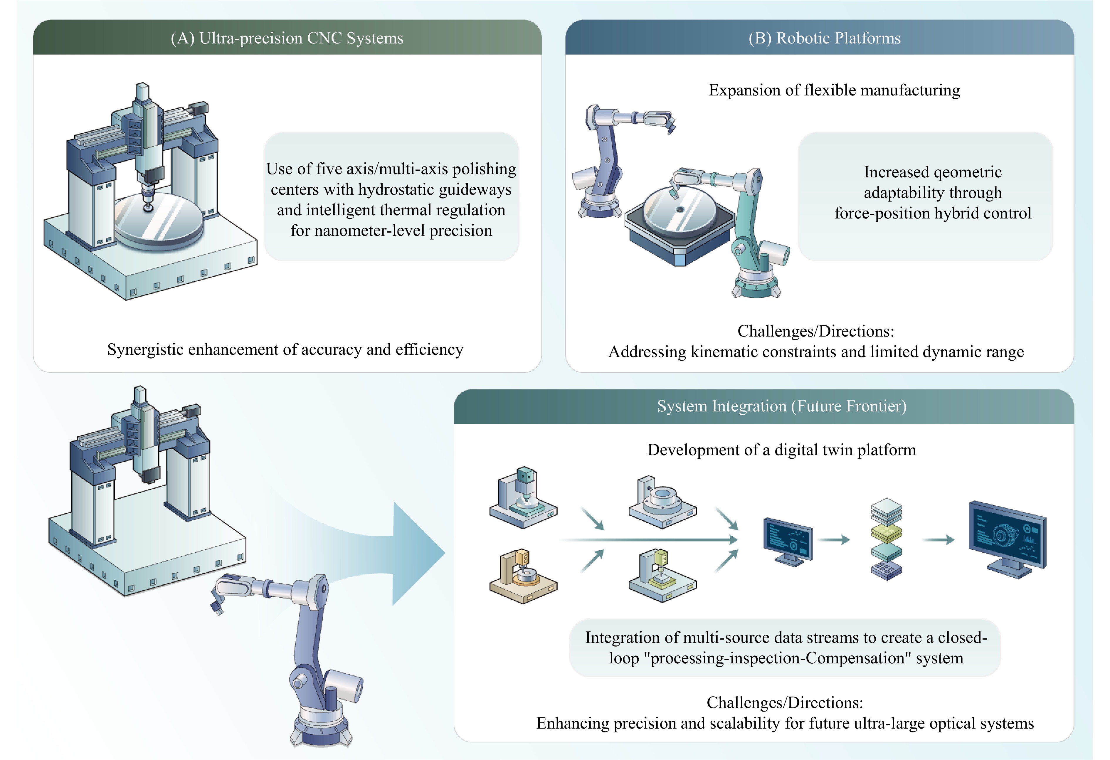
Fig. 27 Schematic overview of large-aperture optical element manufacturing equipment: classification and future trends.
Overall, the success of large-aperture mirror manufacturing depends on the coordinated development of mirror blank fabrication, surface generation (rough and fine grinding), precision polishing and reliable testing123–131. No single technology can independently satisfy all requirements. Instead, the modern fabrication chain relies on hybrid routes that combine efficient generation, controlled grinding, precision polishing and reliable testing.
-
Optical testing is not merely a final verification step; it is an integral part of deterministic fabrication. In the manufacturing of large-aperture mirrors, each round of measurement provides the error map that determines the next material-removal strategy. Therefore, the achievable fabrication accuracy is fundamentally limited by the accuracy, dynamic range, stability, and traceability of the metrology system. Fig. 28 conceptualizes the key role of metrology in the deterministic fabrication loop, mapping predominant testing methods onto the three main mirror production phases: rough generation, polishing/figuring, and segmented system integration. It illustrates the necessary evolution of metrology from high-dynamic-range profiling to nanometer-sensitive wavefront sensing as the optical surface is refined.
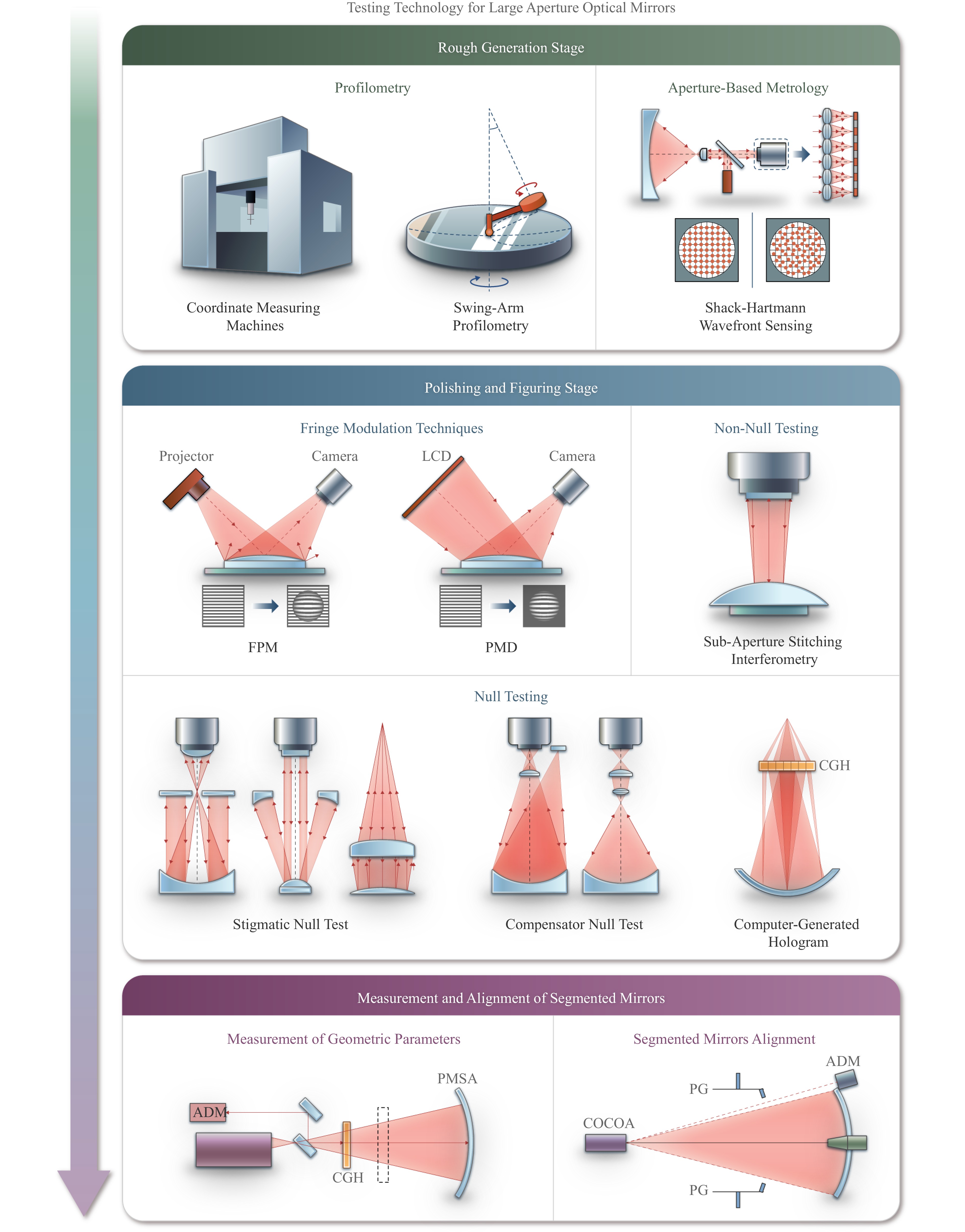
Fig. 28 A panoramic view of testing technologies across the large-aperture mirror manufacturing workflow.
Because the surface condition and accuracy requirement vary substantially across fabrication stages, no single testing method is universally applicable. During rough generation, the surface usually has large figure error, high roughness, and low reflectivity, requiring robust methods with wide dynamic range. During polishing and figuring, the mirror approaches optical quality, and nanometer-level interferometric or wavefront-based methods become essential. For segmented mirrors, additional geometric parameters, such as radius of curvature, segment position, clocking, tilt, piston, and co-phasing error, must also be measured and controlled.
This section therefore classifies optical testing methods according to their role in the fabrication process: global form measurement in rough generation, high-accuracy surface testing in polishing and figuring, and geometric measurement and alignment for segmented mirrors.
-
In the rough generation stage, metrology must tolerate large departures from the nominal surface and must provide sufficiently reliable feedback for subsequent grinding and pre-polishing. The emphasis is not yet final nanometer accuracy, but robust recovery of global form, curvature error, edge tendency, and residual stock distribution. Profilometry, swing-arm profilometry, Shack-Hartmann sensing, and fringe modulation methods are the main techniques used at this stage.
-
Profilometry and coordinate measurement methods (CMM)132–135 (as shown in Fig. 29) obtain discrete surface coordinates along predefined paths and compare them with the nominal optical prescription. They are particularly useful when the surface is still rough or has a large figure error, where interferometric methods may fail because of insufficient reflectivity or excessive wavefront aberration. A coordinate measuring machine, scanning profilometer, or contact/non-contact displacement sensor can provide micrometer-level surface information over a wide dynamic range.
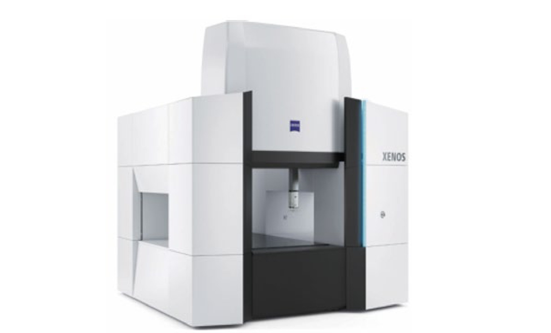
Fig. 29 Zeiss XENOS series CMM139.
In large-aperture mirror manufacturing, coordinate metrology is commonly used as an early-stage feedback tool. For example, GTC used large-scale coordinate measurement (as shown in Fig. 30) for its 36 hexagonal primary mirror segments during the grinding phase107. JWST used a large Leitz CMM to evaluate the beryllium mirror segments during early fabrication136. Similar profilometric approaches were used in the LAMP81,137, Subaru60 (as shown in Fig. 31) , and ELT138 projects to verify mirror blanks (as shown in Fig. 32) , polished surfaces, or segment geometries before higher-precision optical testing was introduced.
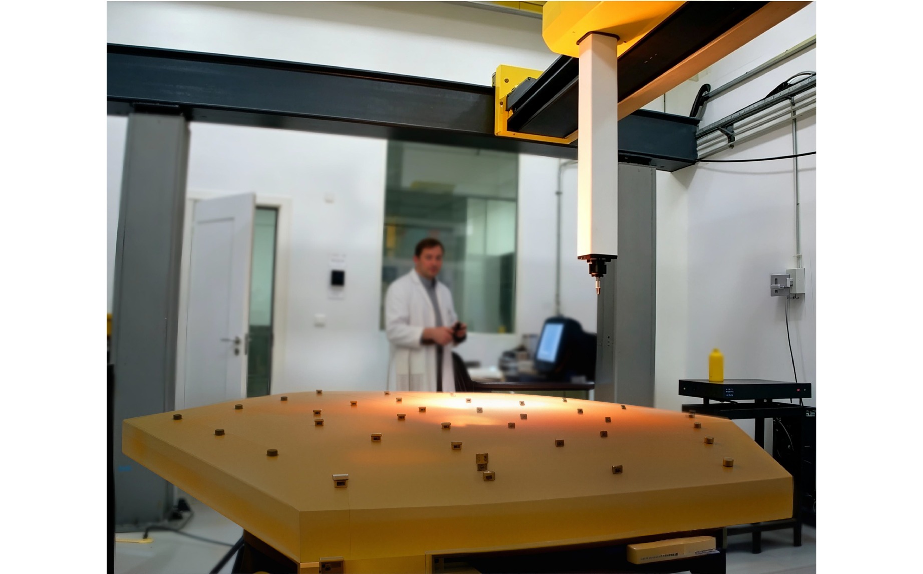
Fig. 30 Large 3D CMM used for GTC mirror segments107.
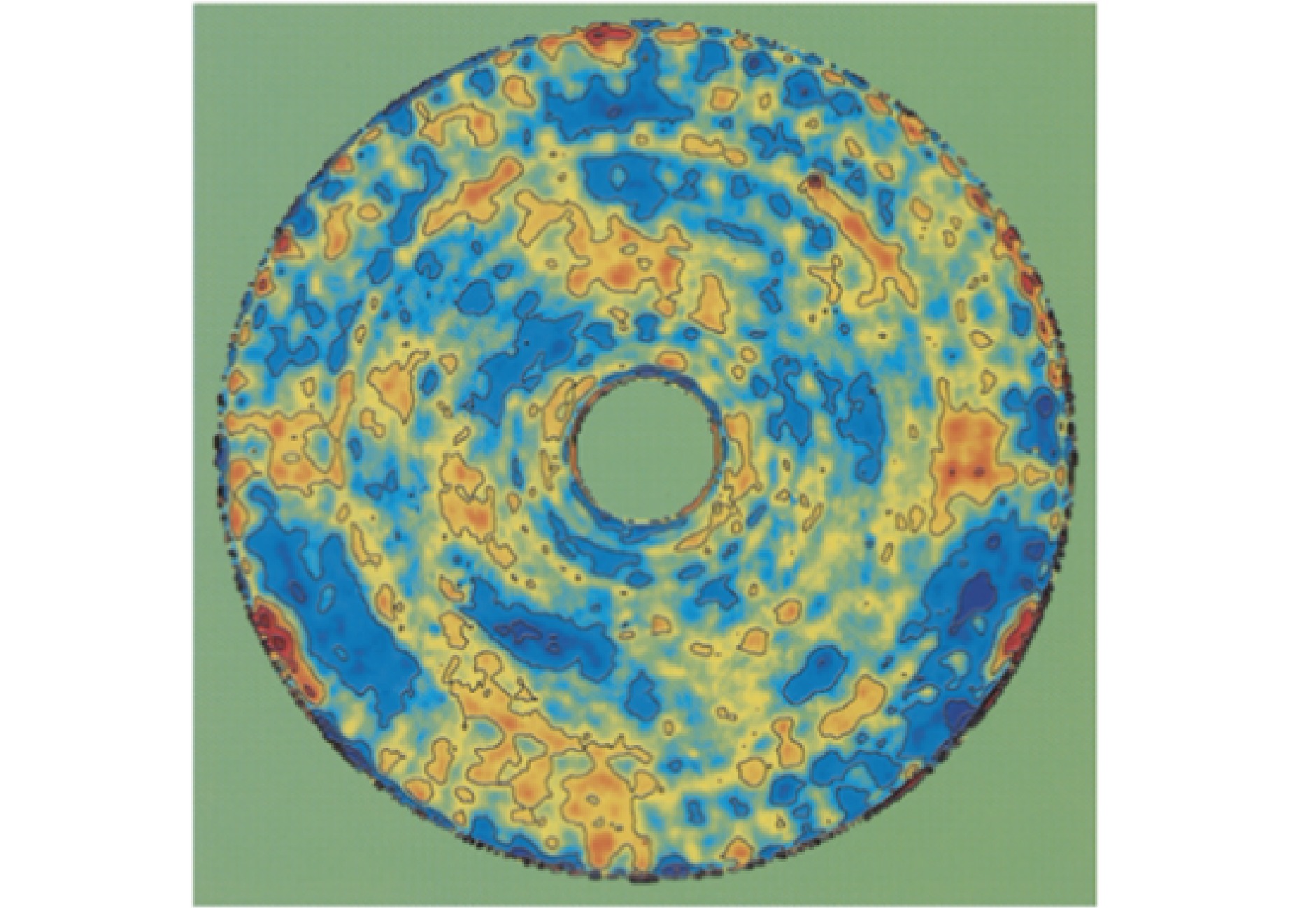
Fig. 31 Surface error map of an 8.2 m primary mirror60.
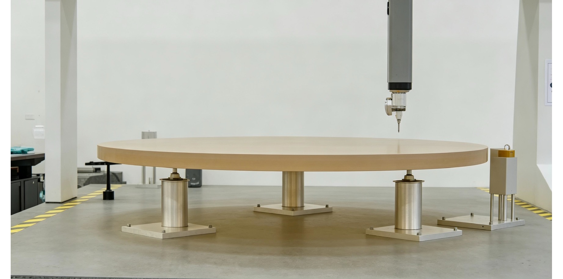
Fig. 32 CMM used in ELT mirror blank measurement138.
The main advantage of profilometry is robustness: it is less sensitive to surface reflectivity and roughness than interferometry. Its limitations are measurement time, mechanical positioning error, probe calibration, and sparse sampling. Therefore, profilometry is best viewed as a global-shape and process-control tool rather than a final acceptance method for optical surfaces.
-
Swing-arm profilometry (as shown in Fig. 33) is a non-contact surface profiling method especially suited to large spherical and aspheric mirrors. The probe arm rotates about a carefully aligned axis so that the sensor follows the best-fit sphere of the test surface, directly measuring departures from that reference. This geometry allows large-aperture surfaces to be measured with high sampling efficiency and a wide dynamic range140,141.
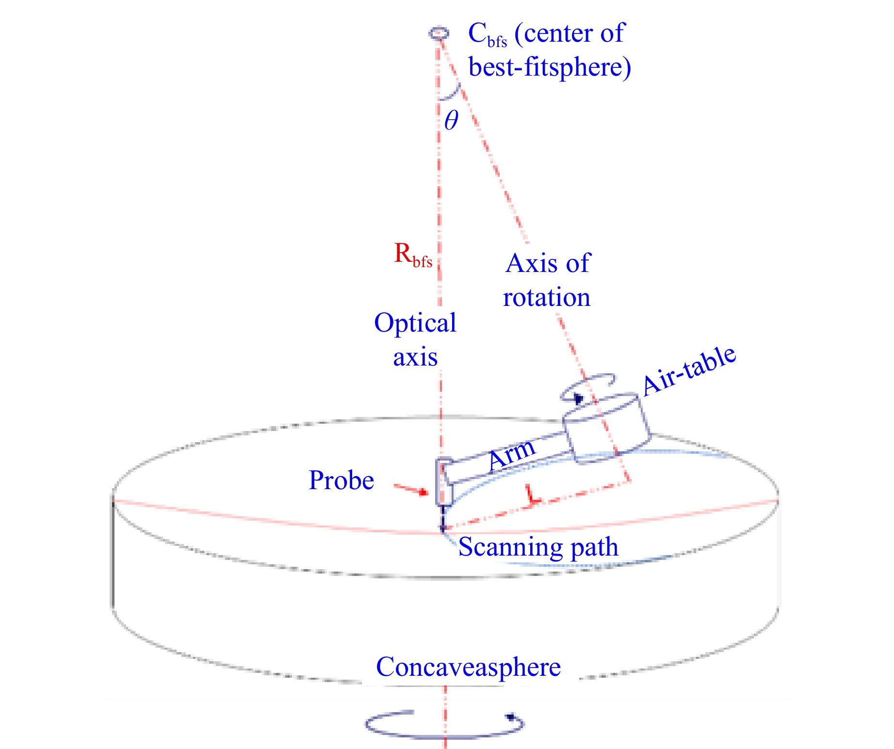
Fig. 33 Swing arm profiler: measuring principle diagram144.
This technique has been adopted in several representative large-mirror projects. The LSST/Rubin secondary mirror was tested using a swing-arm profilometer developed at the University of Arizona142, as shown in Fig. 34. As shown in Fig. 35, Herschel mirror fabrication also used swing-arm profilometry in the rough processing chain143. CIOMP applied a self-developed swing-arm profilometer to the 4.03 m SiC aspheric mirror from grinding to pre-polishing, as shown in Figs. 36, 37, and the results were consistent with subsequent interferometric measurements22.
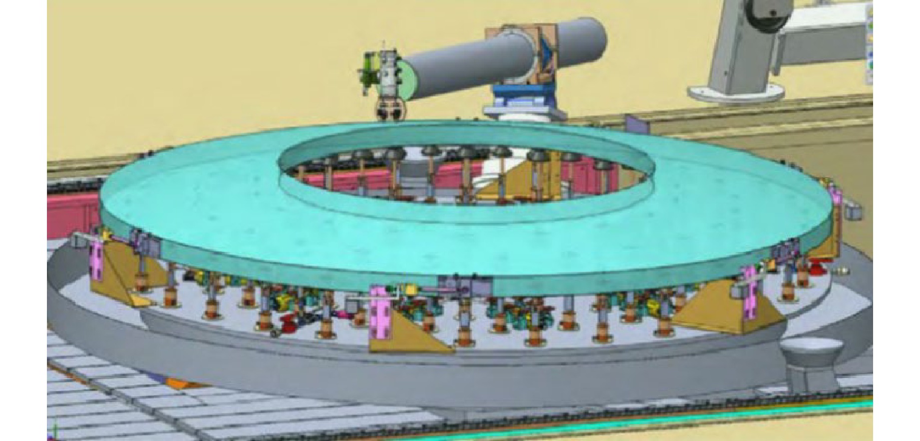
Fig. 34 LSST swing-arm contour meter (SOCMM): inspection schematic142.
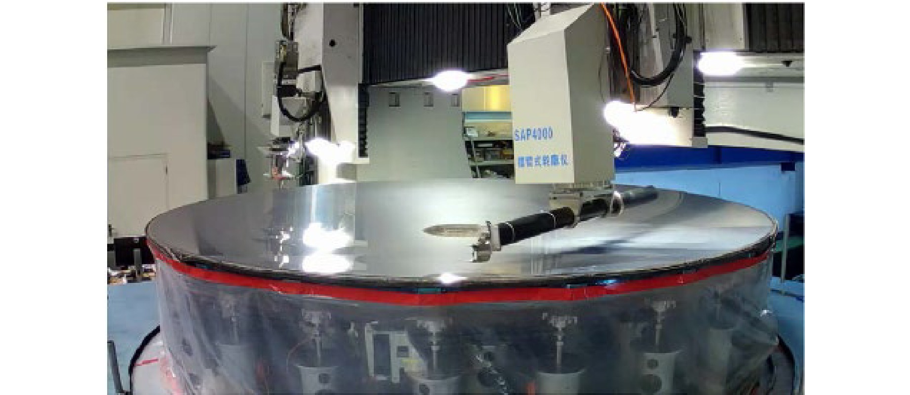
Fig. 36 Surface figure characterization of a 4 m aspheric mirror via swing-arm profilometry (SAP) testing22.
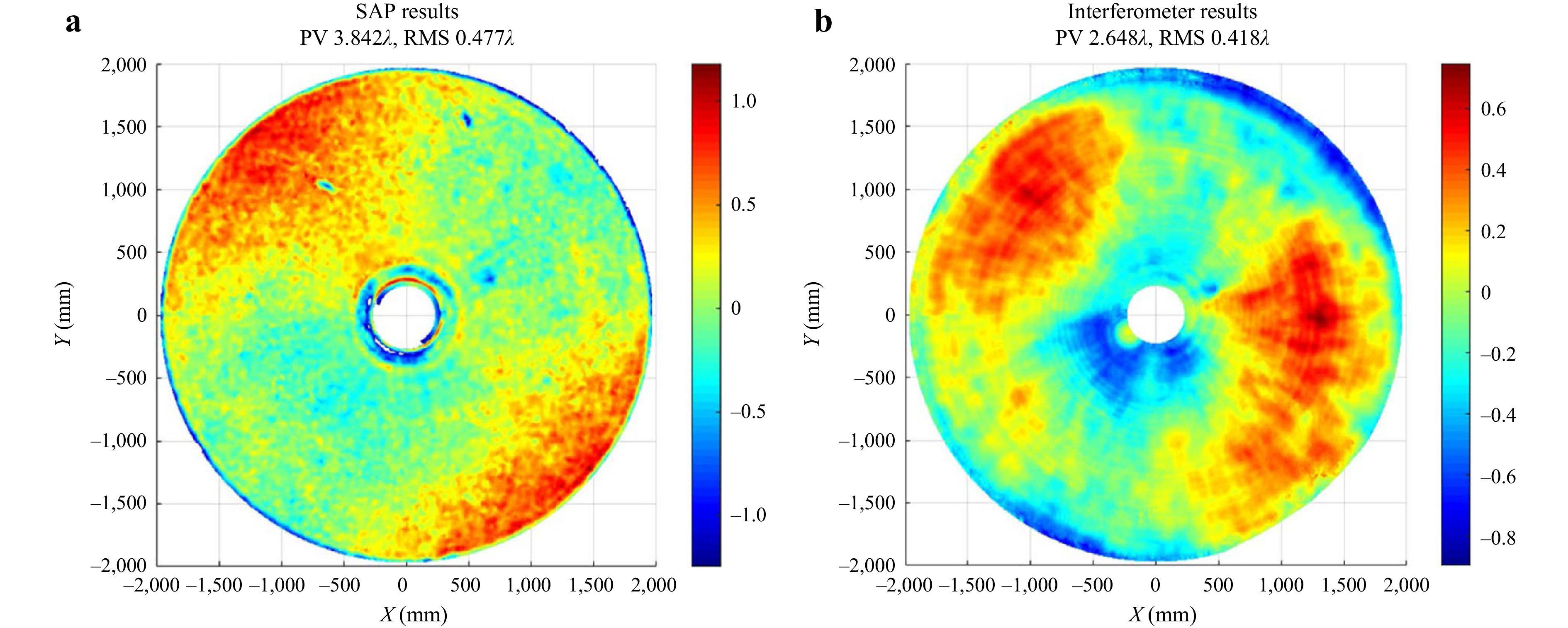
Fig. 37 Surface analysis of 4 m aspheric mirror via SAP testing22. a Surface analysis results via SAP testing. b Surface analysis results via interferometer.
Swing-arm profilometry is particularly effective for in-process measurement because it can cover large apertures without requiring a full-aperture null test. However, its accuracy depends strongly on rotary-axis calibration, sensor linearity, arm deformation, and error-separation algorithms. It is therefore most powerful when combined with interferometry, CGH testing, or deflectometry in a multi-source metrology strategy.
-
Shack-Hartmann wavefront sensing reconstructs surface or wavefront error by measuring local wavefront slopes. Compared with classical Hartmann tests, the use of microlens arrays improves spot localization and enables faster wavefront reconstruction. This method is attractive for rough and intermediate fabrication stages because it is non-contact, relatively simple in optical configuration, and capable of acquiring large-area slope information efficiently.
In large telescope manufacturing, Shack-Hartmann or scanning Shack-Hartmann methods (as shown in Figs. 38, 39) have been used as practical tools for characterizing wavefront and mid-spatial-frequency errors. JWST mirror fabrication, for example, used an infrared scanning Shack-Hartmann sensor variant to evaluate segment errors at intermediate stages133. In other projects, Shack-Hartmann methods have served as complementary metrology to profilometry and interferometry.
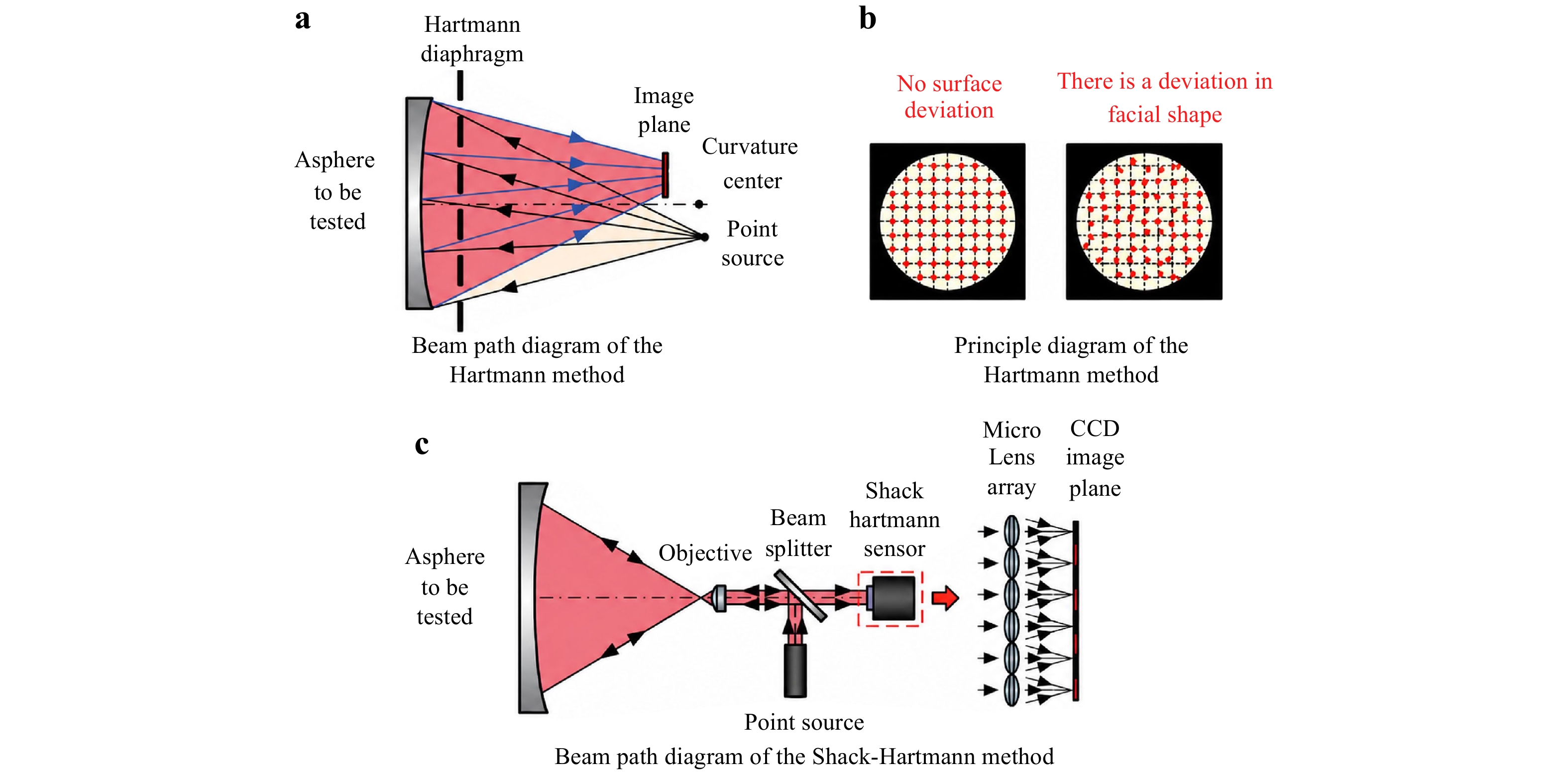
Fig. 38 Principle schematics and measurement results of Hartmann and Shack-Hartmann wavefront sensing methods139. a Beam path diagram of the Hartmann method. b Principle diagram of the Hartmann method. c Beam path diagram of the Shack-Hartmann method.
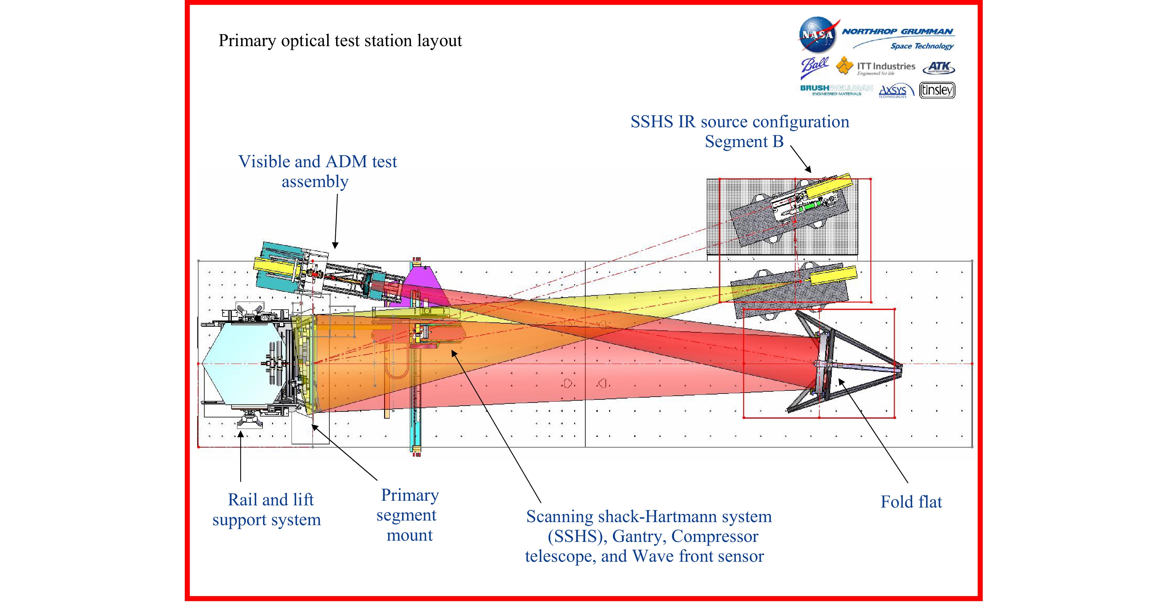
Fig. 39 Optical layout schematic of the SSHS43.
Its main limitations arise from microlens aperture, spatial sampling density, calibration, and reconstruction error87,113,145,146. As a result, Shack-Hartmann sensing is most useful as a rapid slope-based measurement method rather than a universal replacement for high-accuracy interferometry.
-
Fringe modulation methods, including structured light (as shown in Fig. 40), Ronchi testing, and phase measuring deflectometry, infer surface shape from the deformation of projected or reflected fringe patterns147,148. For specular optical surfaces, phase measuring deflectometry is particularly useful because it measures slope information with a large dynamic range and relatively simple hardware149.
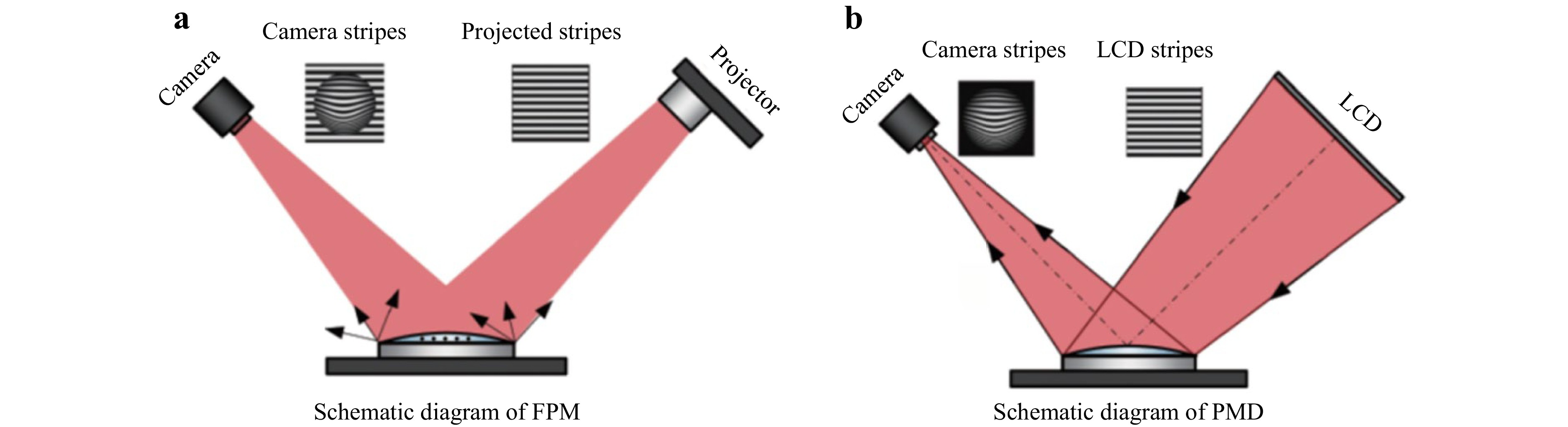
Fig. 40 Schematic of structured light methods129. a Schematic diagram of FPM. b Schematic diagram of PMD.
The SCOTS system developed at the University of Arizona is a representative implementation of this idea. It has been used to test large off-axis aspheric mirrors, including GMT segments, where its results showed good agreement with interferometric measurements after calibration and correction. As shown in Fig. 41, similar deflectometric approaches are increasingly used as complementary tools for complex aspheres whose slope range exceeds that of conventional interferometric setups150,151.
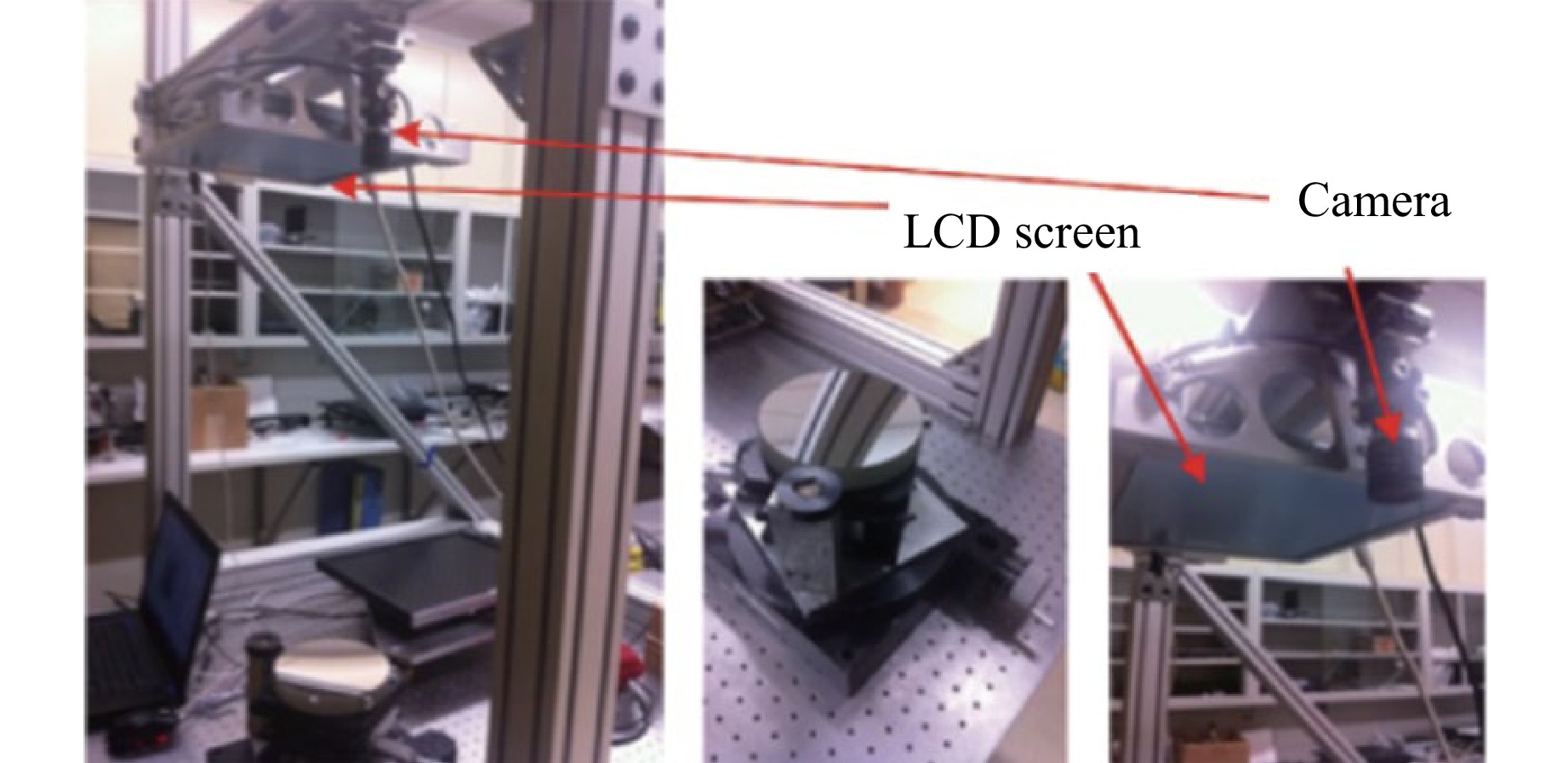
Fig. 41 Optical layout of the SCOTS system151.
The strength of fringe modulation methods lies in their large dynamic range, non-contact operation, and suitability for difficult aspheric surfaces. Their limitations include calibration sensitivity, coordinate-system reconstruction, iterative computation, and dependence on accurate geometric modeling. Therefore, they are often used in combination with interferometry rather than as an isolated final test. The fringe modulation technology is also constantly evolving. In recent years, it has been deeply explored in areas such as the integration with deep learning152–154, projection systems155, Phase retrieval156, encoding and labeling157, defocus measurement158, and 3D reconstruction154.
-
Once polishing and deterministic figuring begin, surface errors must be reduced to the nanometer scale. At this stage, interferometric techniques become the main metrology route. Depending on whether the nominal aspheric aberration is optically compensated, these techniques can be divided into non-null and null testing methods.
-
Sub-aperture stitching interferometry measures a large mirror by dividing it into smaller overlapping regions and reconstructing the full-aperture surface through stitching algorithms. As shown in Figs. 42, 43, this method avoids the need for a single full-aperture reference optic and is therefore highly valuable for large convex aspheres and mirrors whose size exceeds available interferometric test optics159–162.
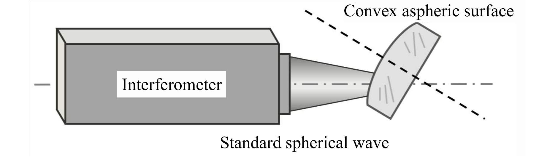
Fig. 42 Schematic of sub-aperture stitching interferometry159.
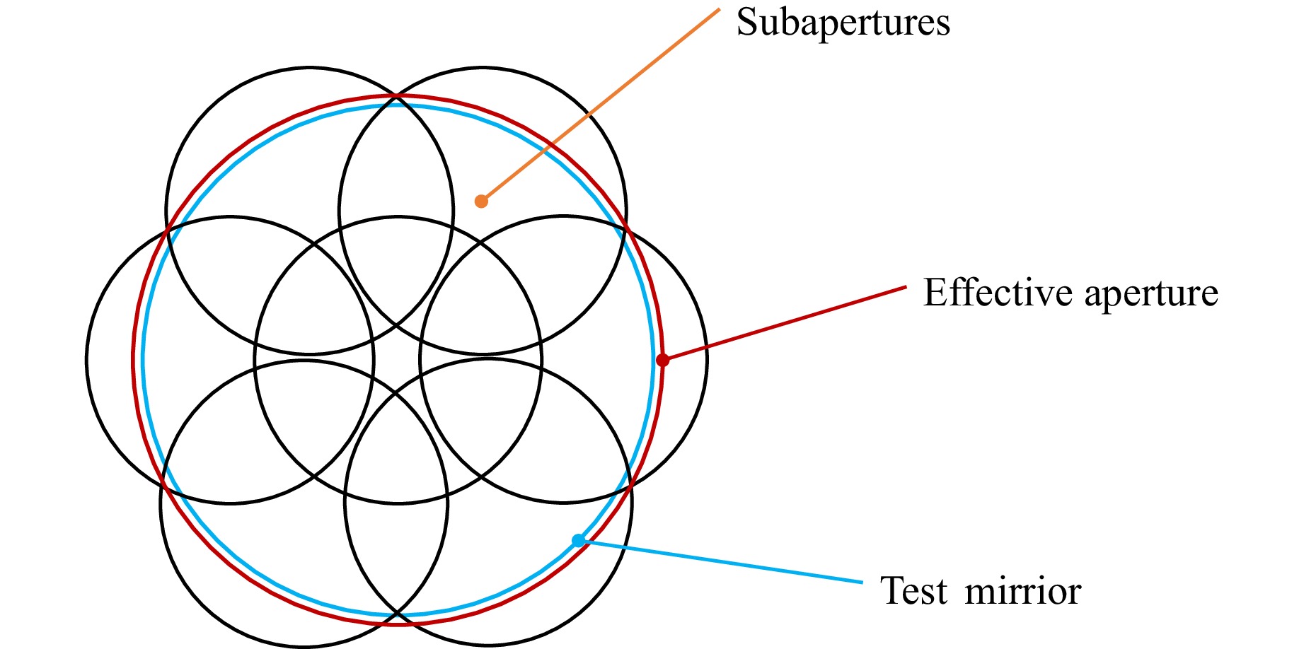
Fig. 43 Schematic of the circular sub-aperture layout.
Representative applications include the LSST/Rubin secondary mirror, where sub-aperture Fizeau testing (as shown in Fig. 44) was used to reconstruct the full-aperture surface163,164; the TMT secondary mirror, where multiple off-axis aspheric test plates (as shown in Fig. 45) were proposed to deal with the absence of a central aperture164; and the ELT M2 mirror, where sectorial sub-aperture stitching (as shown in Figs. 46, 47) was used for the 4.25 m convex aspheric surface109,165.
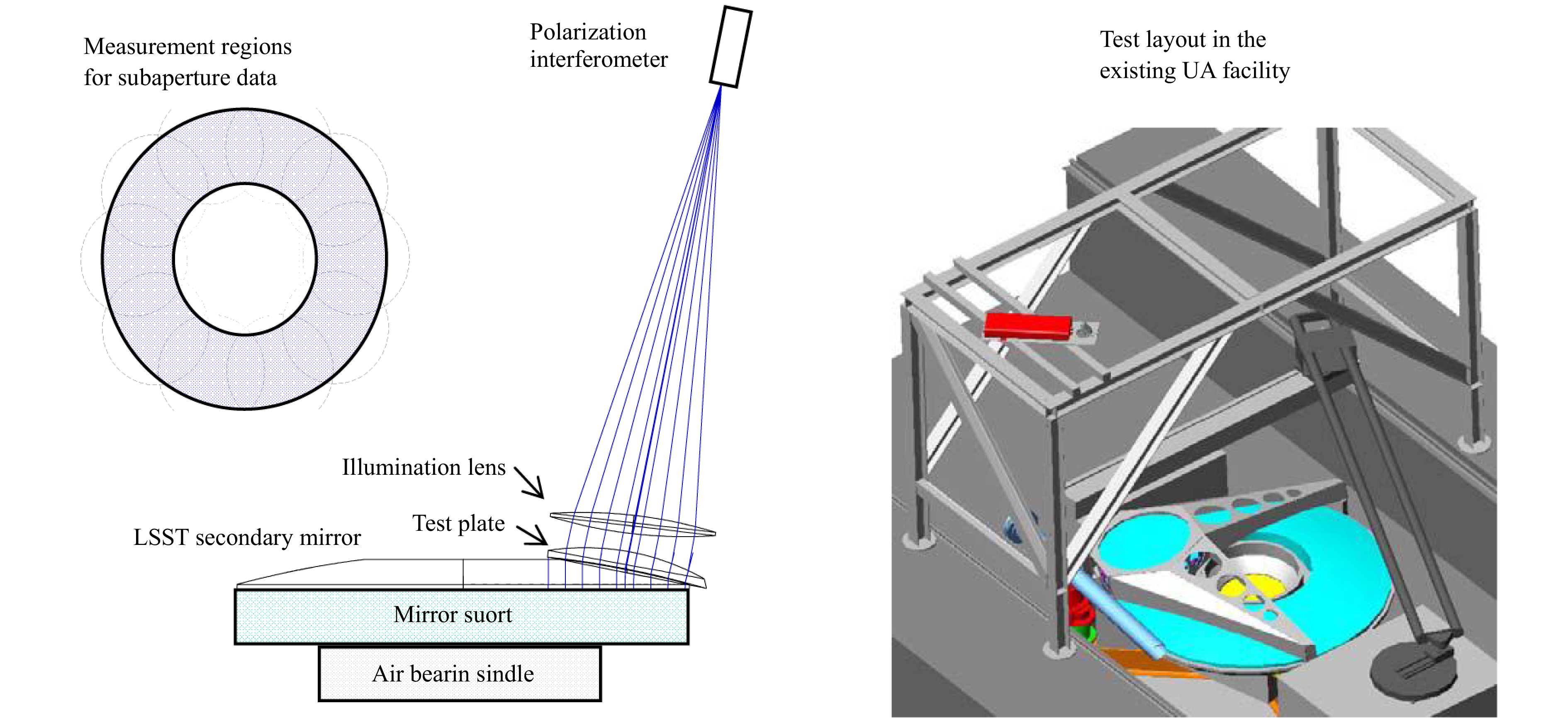
Fig. 44 Layout for LSST secondary mirror test in the Optical Sciences shop at the University of Arizona164.
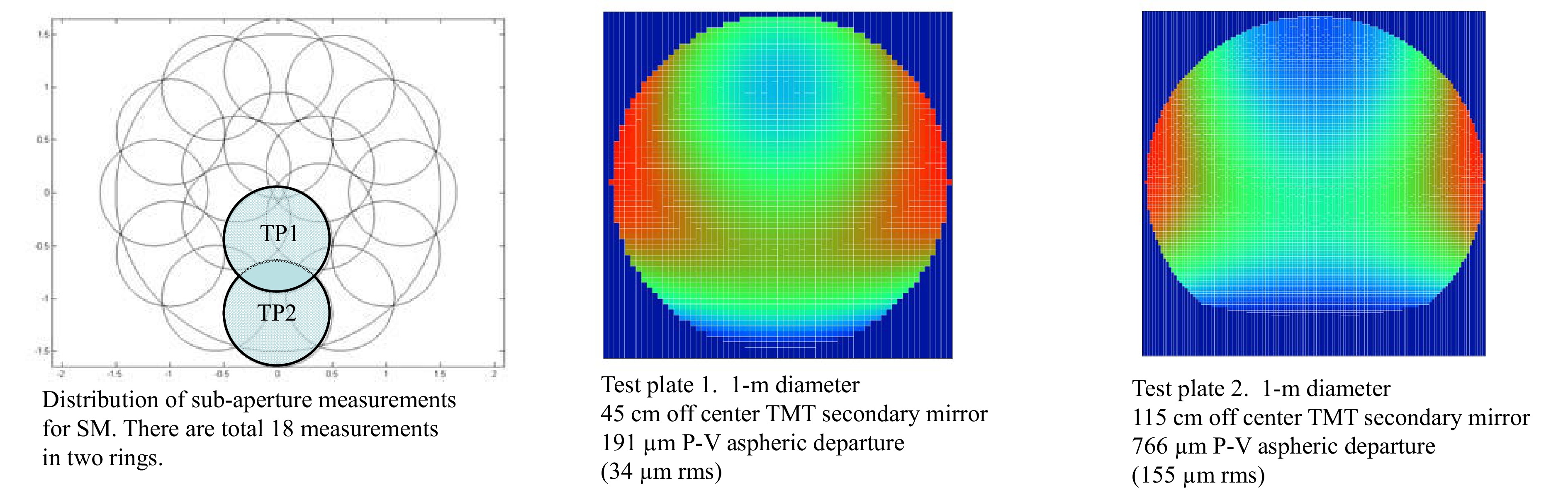
Fig. 45 Layout and aspheric departure of test plates for the Fizeau test of the TMT secondary mirror164.
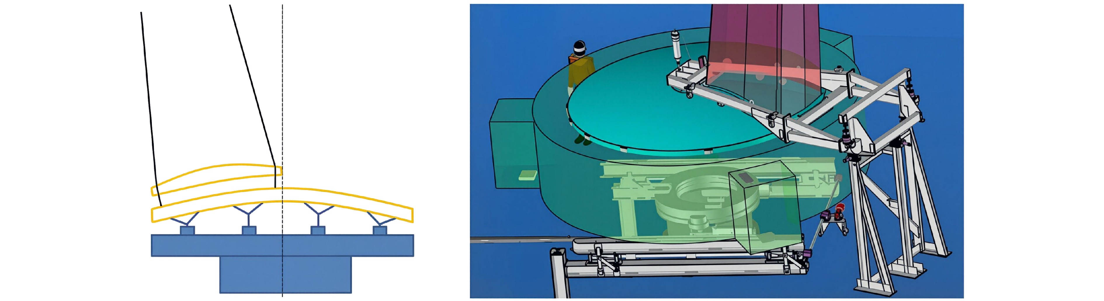
Fig. 46 ELT M2 test bench concept at Safran REOSC. An aspheric reference plate is used for sub-aperture Fizeau testing109.
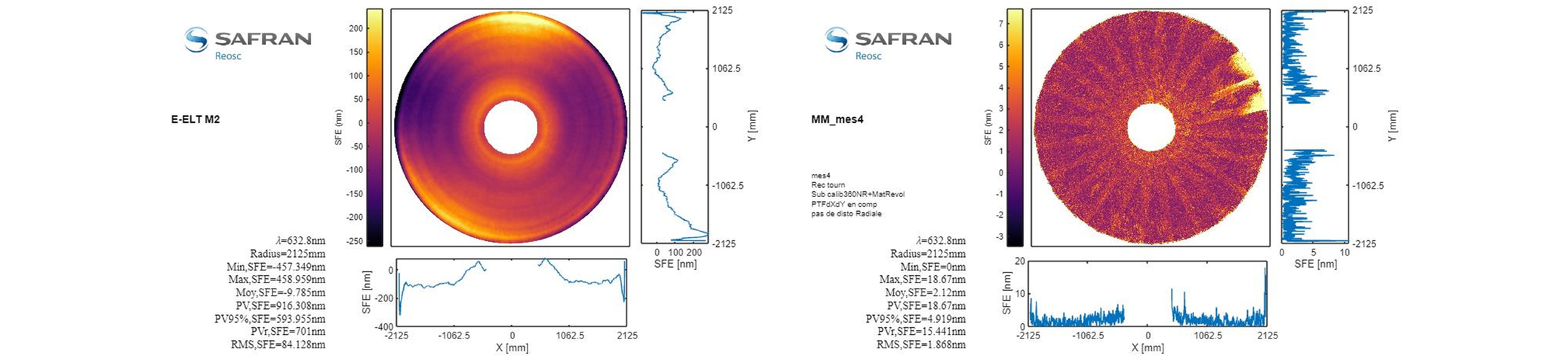
Fig. 47 ELT M2 surface figure error map after six polishing iterations/mismatch map obtained after stitching165.
The method offers high accuracy and strong adaptability, but its performance is limited by stage positioning, overlap accuracy, systematic error coupling, environmental stability, and stitching algorithm robustness. For this reason, modern stitching interferometry increasingly relies on calibrated motion systems, redundant overlap strategies, and uncertainty analysis166–174.
-
Null testing converts the ideal reflected wavefront of an aspheric surface into a plane or spherical wave so that residual fringes directly represent surface error. It is the dominant approach for high-precision polishing-stage and final testing of large optical mirrors.
-
Stigmatic null tests (as shown in Figs. 48−50) use the conjugate-point property of conic surfaces and can achieve very high accuracy for suitable quadric mirrors. The classical Hindle test and its variants belong to this category. These methods are optically elegant and accurate, but they usually require large, high-quality auxiliary optics and precise alignment27,175.

Fig. 48 Stigmatic null test optical path175.
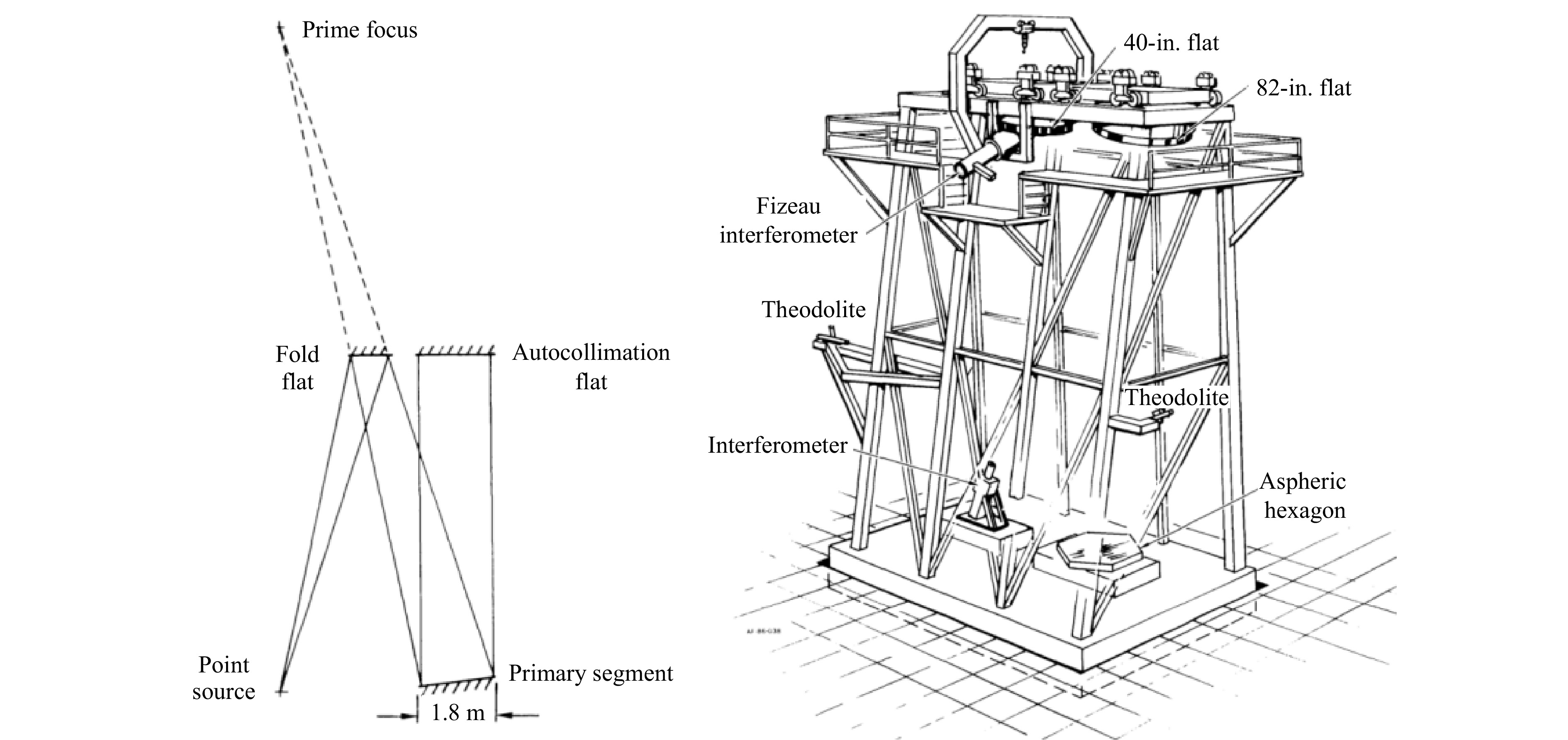
Fig. 50 a Folded autocollimation test and b autocollimation test facility178.
For segmented mirrors, related null or autocollimation configurations have been used to test individual segments. Keck, for instance, employed interferometric folded autocollimation testing during the fine polishing of its hexagonal segments5, 27, 74, 104, 176, 177. This illustrates the role of stigmatic or near-stigmatic null concepts in segment-level verification.

Fig. 49 Hindle shell interference compensation test optical path175.
-
Compensator null tests use refractive or reflective optics to compensate the nominal aberration of an aspheric mirror179. As shown in Fig. 51, Dall180 and Offner181 compensators are common examples. This approach is suitable for rotationally symmetric aspheres and has long been a standard method for high-precision testing of large telescope mirrors.
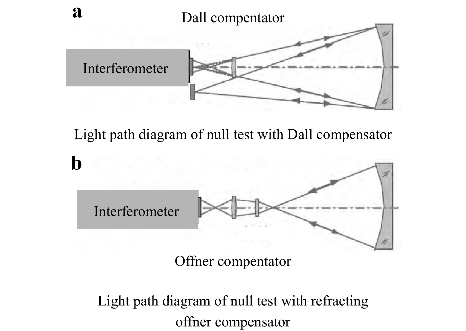
Fig. 51 Optical path diagrams for testing aspheric surfaces using the compensator mirror method189.
Several flagship projects demonstrate its importance. The Hubble Space Telescope primary mirror used a reflective null compensator, as shown in Figs. 52, 53, although the well-known testing error in that project also became a historical reminder that null-test calibration and independent verification are essential180,182–185. Gemini used infrared and visible-light null compensators at different fabrication stages186–188, as shown in Fig. 54. LSST/Rubin M1 was tested using an Offner null compensator, as shown in Figs. 55, 56, with CGH-based verification of the compensator2,106.
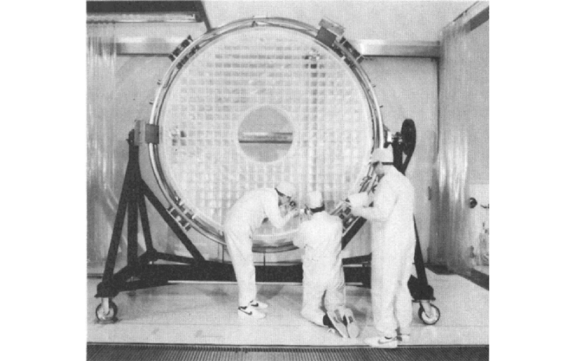
Fig. 52 Primary mirror of the Hubble Space Telescope182.
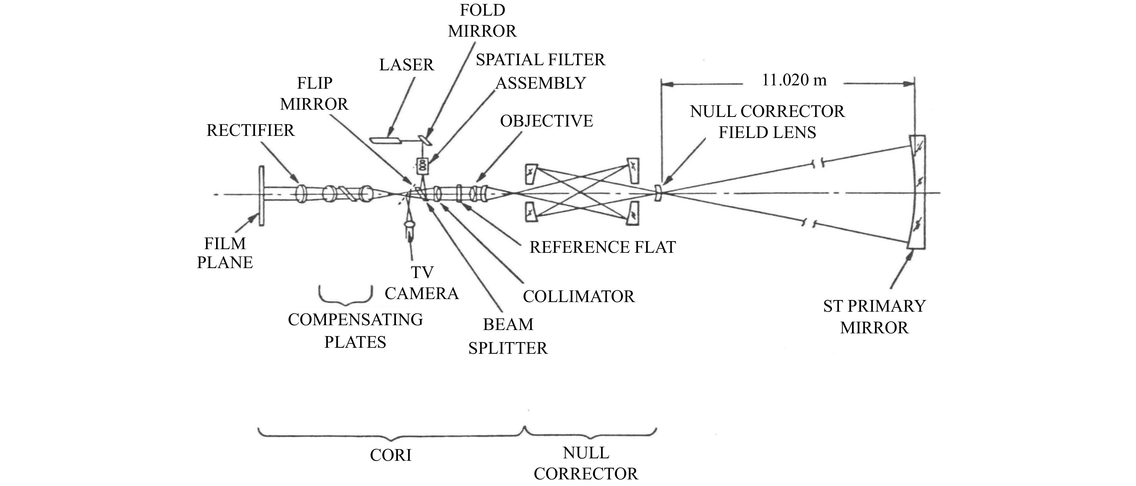
Fig. 53 Test optical path for the Hubble Space Telescope primary mirror182.
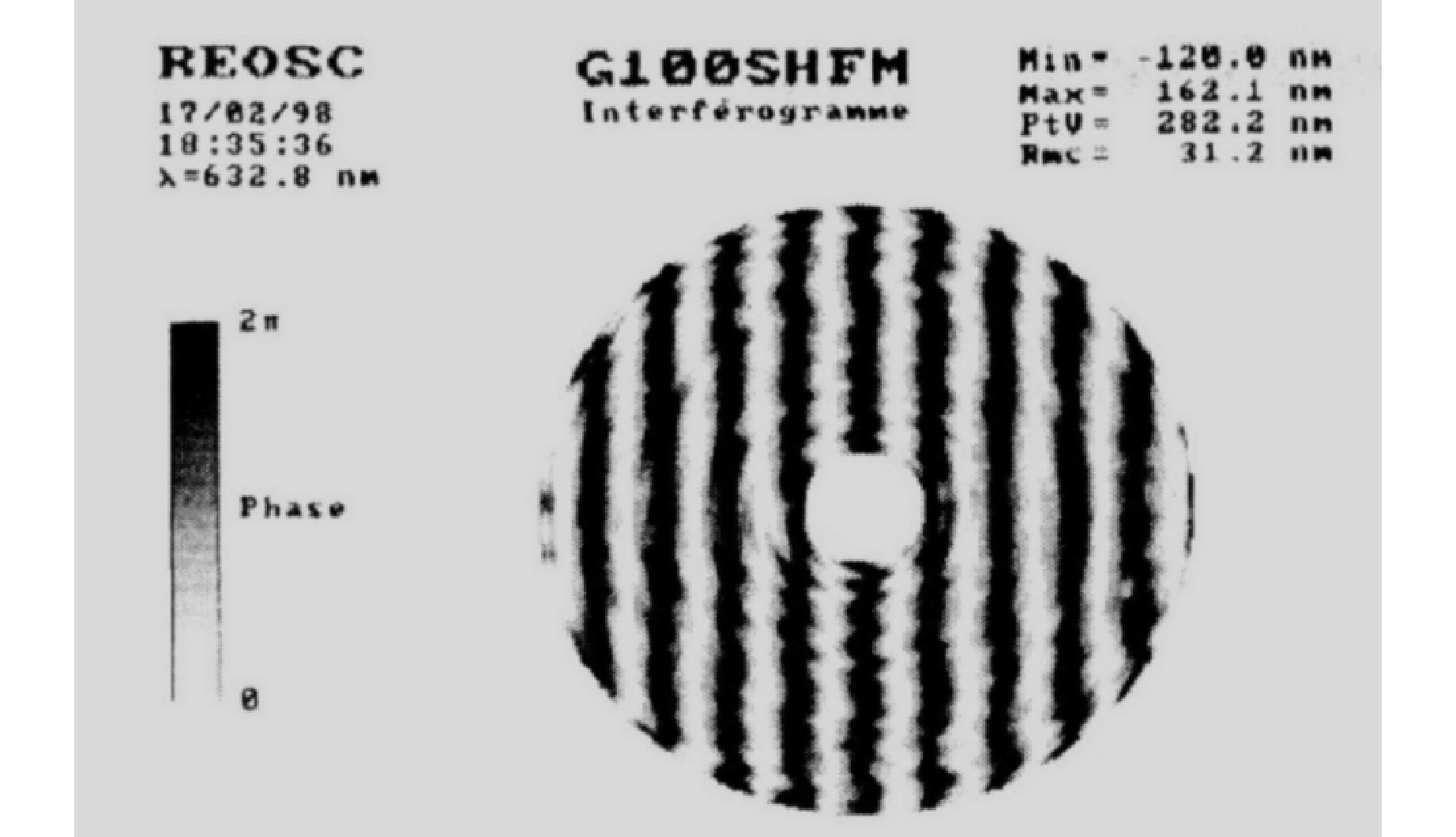
Fig. 54 Interferogram of the Gemini primary mirror testing188.
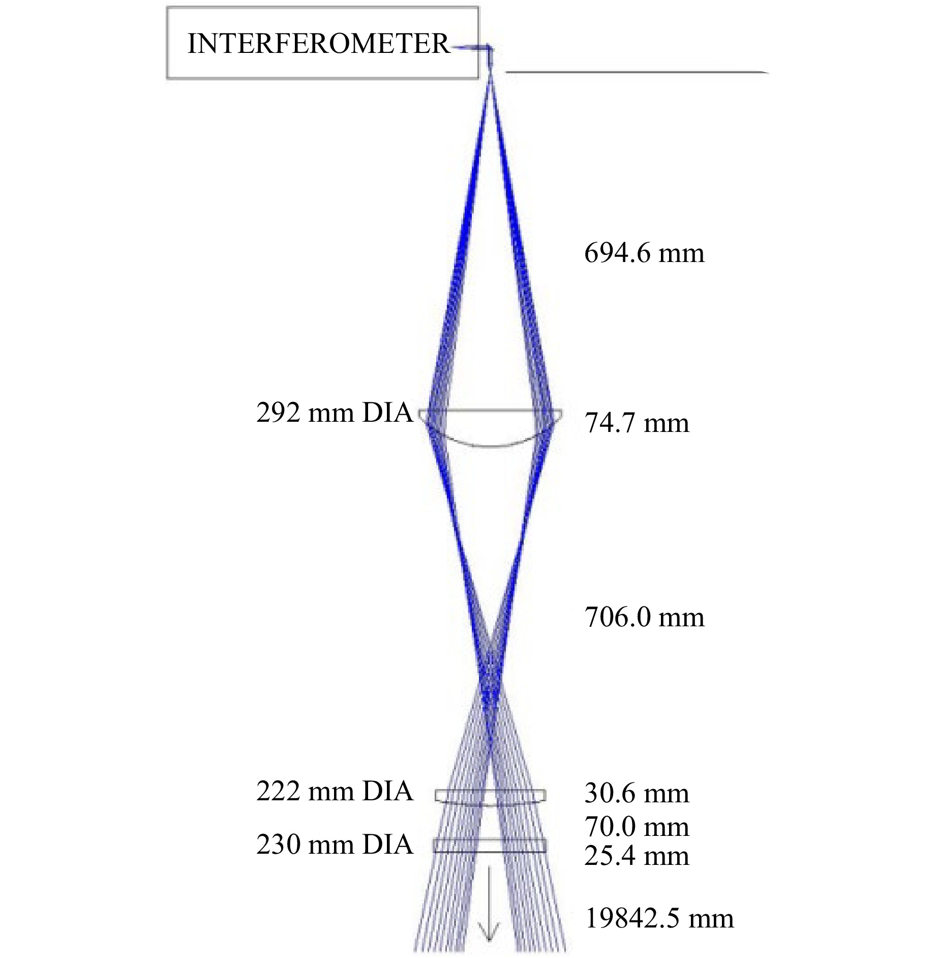
Fig. 55 Null corrector layout for M1 (two-element Offner)2.
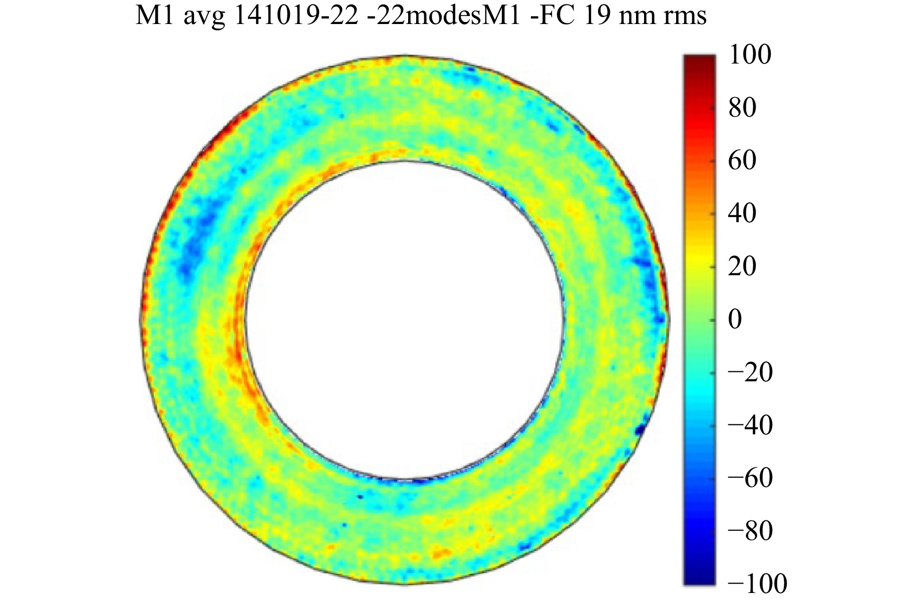
Fig. 56 Surface Figure Error Map of M1106.
The method provides high accuracy but is limited by compensator design, fabrication, alignment sensitivity, and lack of universality. For convex or highly aspheric surfaces, the required auxiliary optics can become large or difficult to manufacture, motivating the use of CGH-assisted, partial-null, or stitching-based configurations.
-
Computer-generated hologram testing uses diffractive structures to generate the desired reference wavefront for an aspheric or freeform surface. Compared with conventional compensators, CGHs can encode complex wavefronts and alignment features, making them particularly suitable for large aspheres, off-axis mirrors, and segmented mirror elements190.
CGH191 testing (as shown in Fig. 57) has been widely adopted in major projects. SDSS used CGH-assisted interferometry to simplify testing of convex aspheric components. GTC used CGH testing (as shown in Fig. 58) in its segment fabrication and global evaluation process105. LSST/Rubin used CGH testing for M3 and for verification of null configurations191, as shown in Figs. 59, 60. GMT segment testing employed CGH-based null interferometry (as shown in Fig. 61) for large off-axis segments192. Seimei used CGH real-time testing (as shown in Fig. 62) in segment fabrication61,193, while CIOMP combined CGH null testing with swing-arm profilometry and phase-shifting deflectometry for the 4.03 m SiC mirror.
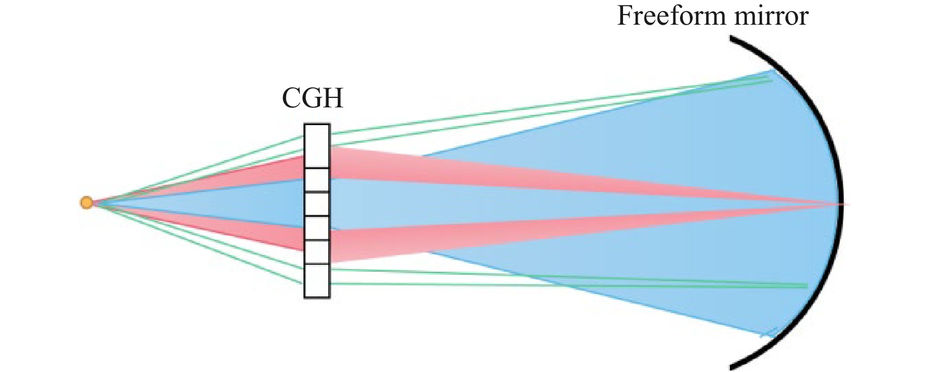
Fig. 57 Schematic of the CGH testing principle.
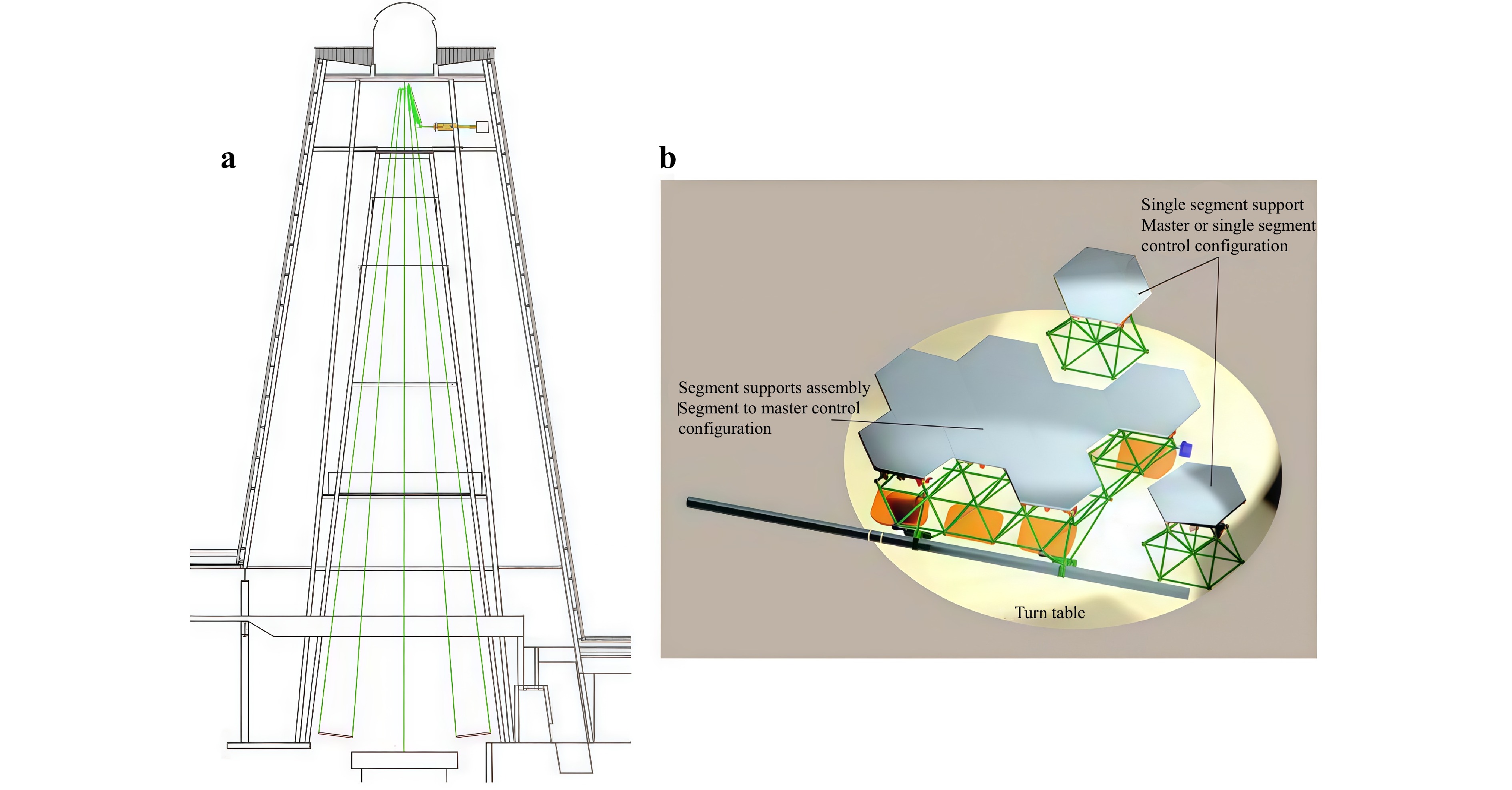
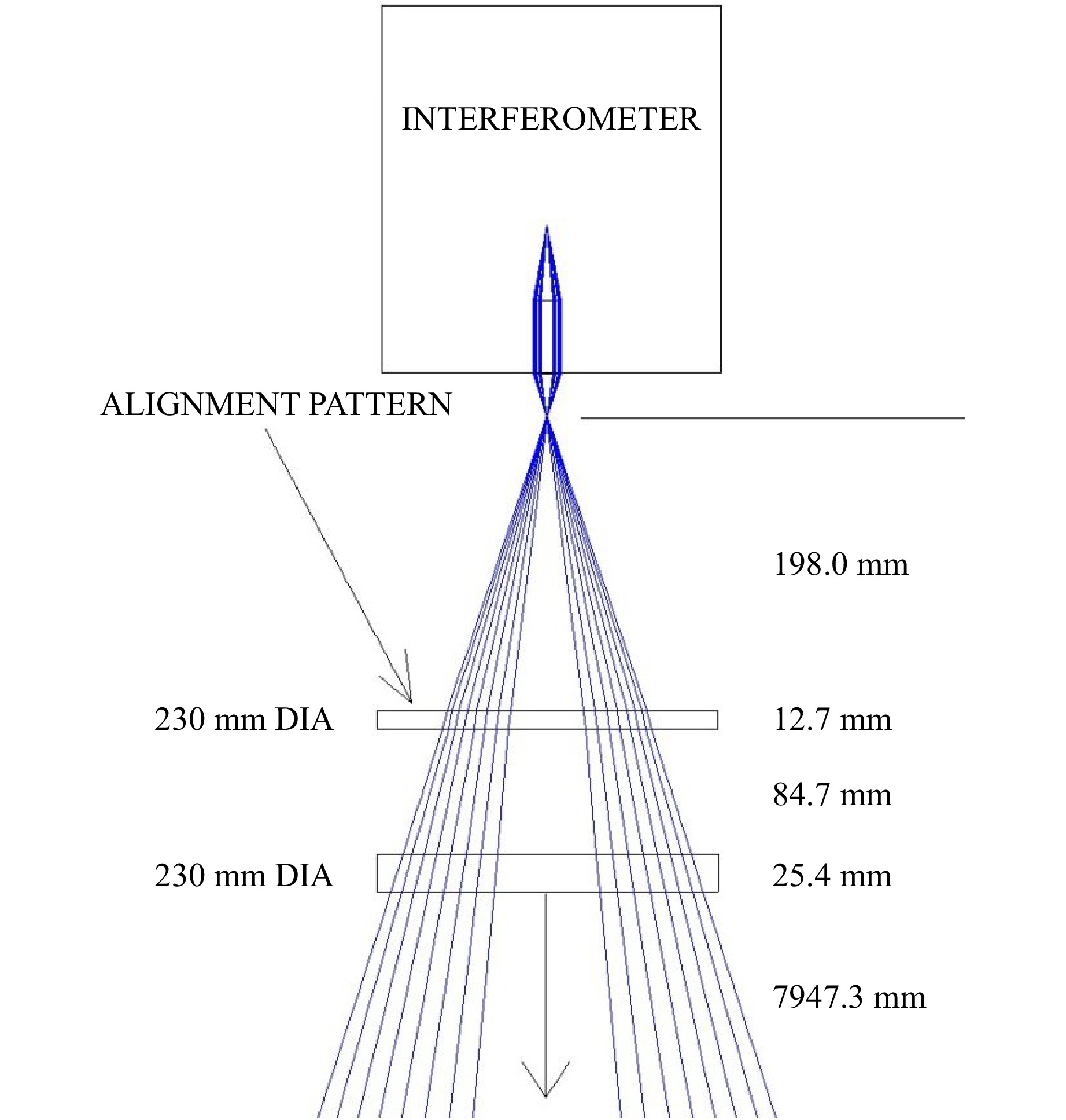
Fig. 59 CGH test configuration for M3191.
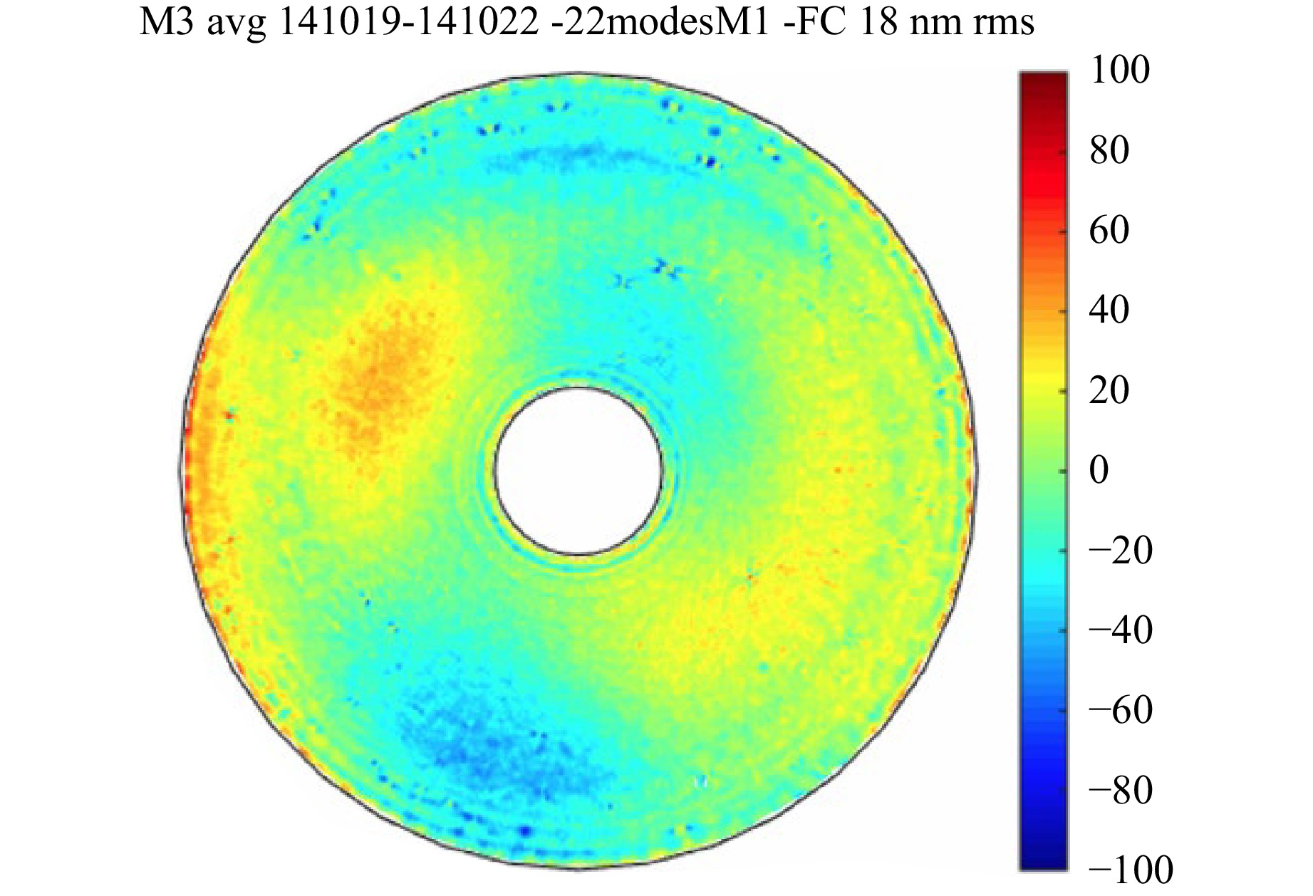
Fig. 60 Residual surface figure of M3 following active optics correction136.

Fig. 61 GMT primary mirror is tested inside a 28 m test facility75.
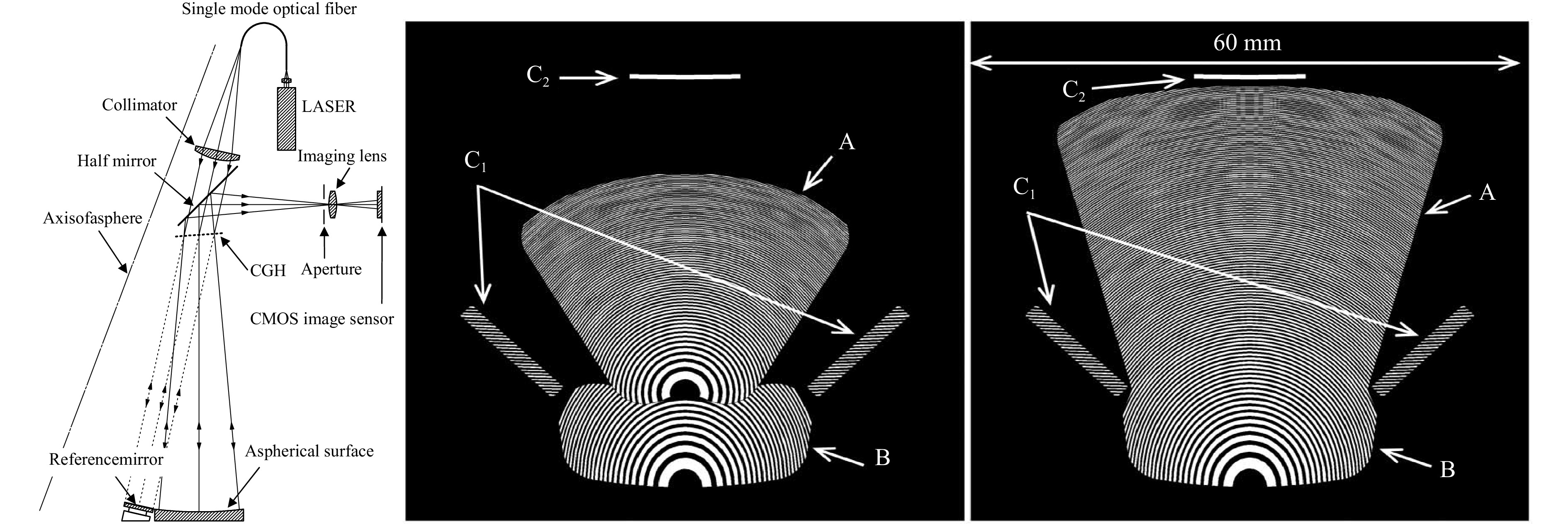
Fig. 62 CGH splits the incident beam into a test beam and a reference beam (left); CGH pattern (right)201.
CGH testing has become one of the most versatile high-precision methods for modern large-aperture optical fabrication194–200. Its limitations are mainly associated with CGH fabrication error, diffraction-order management, alignment sensitivity, substrate error, and absolute calibration. Consequently, CGH testing is most reliable when supported by independent verification, error budgeting, and cross-checking with other metrology methods.
-
For segmented mirrors, surface figure testing alone is insufficient. Each segment must also satisfy geometric and assembly requirements, including radius of curvature, segment position, tilt, clocking, piston, edge matching, and co-phasing. These parameters determine whether independently fabricated segments can form an equivalent continuous aperture.
Radius-of-curvature control is a representative example. In JWST, each beryllium segment was equipped with a RoC actuation system, but excessive correction would introduce residual surface error. Therefore, accurate RoC measurement using interferometry, CGH, absolute distance measurement, and calibration optics was essential for reducing the burden on active correction22, as shown in Fig. 63.
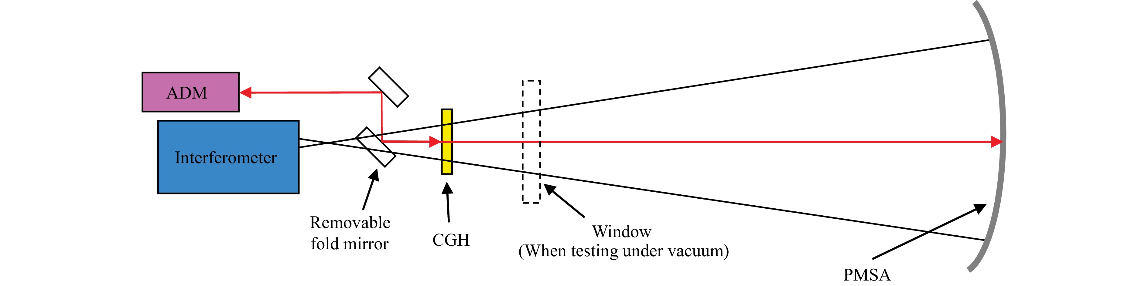
Fig. 63 Schematic of the RoC measurement system22.
Alignment and co-phasing require a staged strategy. As shown in Fig. 64, JWST used photogrammetry for coarse segment positioning, center-of-curvature optical measurements for intermediate alignment, and multi-wavelength interferometric correction for fine phasing202. Large ground-based segmented telescopes such as ELT and TMT extend the same principle to hundreds of segments, requiring robust segment-level metrology, actuator calibration, and wavefront control203,204.
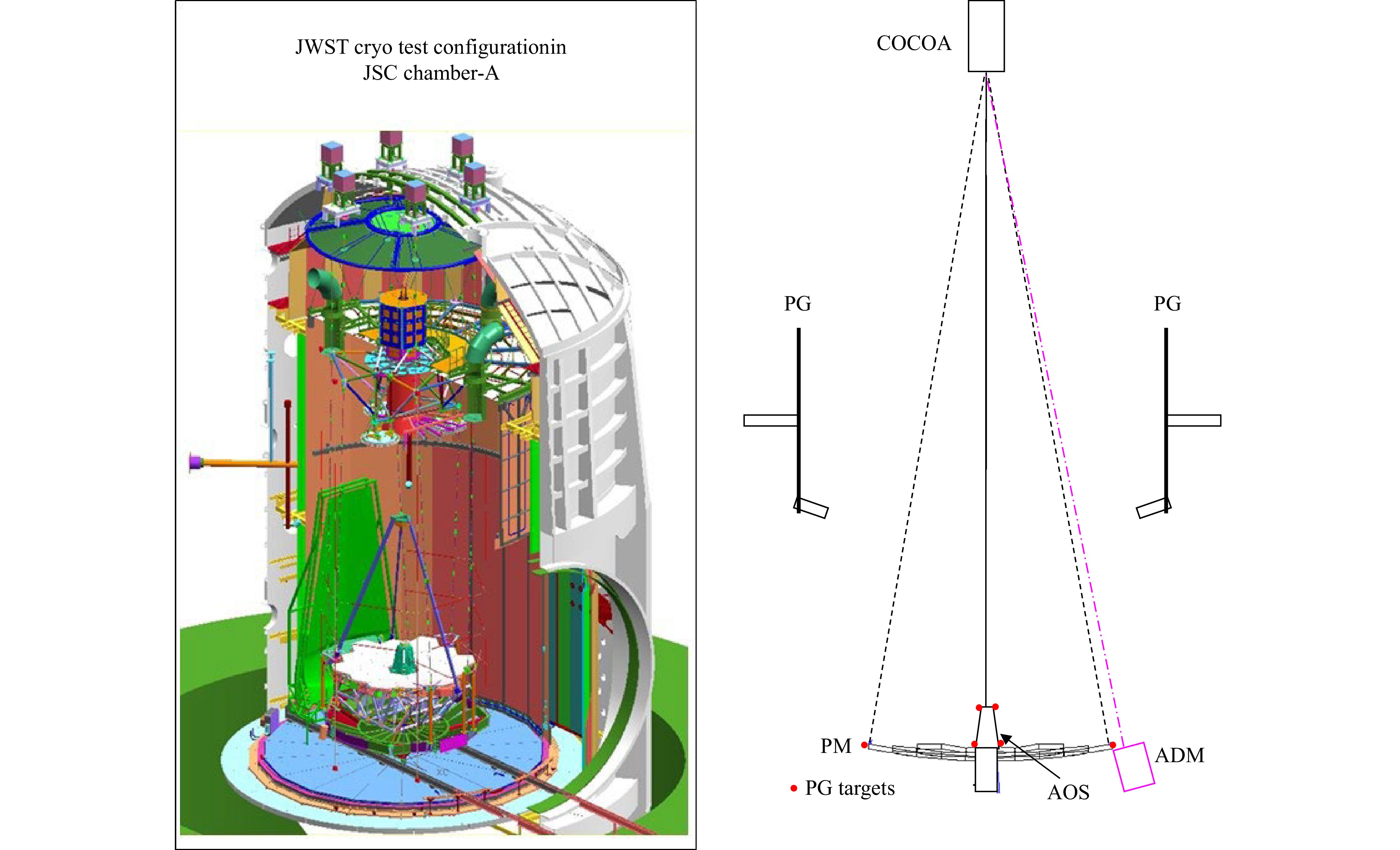
Fig. 64 Model and schematic of the test setup202.
-
The testing methods used in large-aperture mirror fabrication form a staged and complementary system. Rough-stage methods provide wide dynamic range and robustness; polishing-stage methods provide nanometer-scale sensitivity; segmented-mirror methods add geometric consistency and co-phasing control. The most successful projects do not rely on a single method, but on cross-validated metrology chains that connect fabrication, measurement, correction, and acceptance.
In a complete manufacturing flow, a large-aperture optical mirror typically undergoes stages from milling/grinding, loose-abrasive grinding, polishing, and figure finishing, to iterative metrology and final acceptance. Fig. 65 consolidates the staged and complementary nature of optical testing into a hierarchical framework. It should be noted that this schematic primarily synthesizes representative cases and technologies from the open literature, as reviewed in this article. Due to limitations in publicly disclosed information and the review's focus on key technologies, the following figures showcase specific projects and associated techniques discussed herein. This framework visually affirms the principle that no single method is sufficient; rather, a cross-validated metrology chain-encompassing techniques from laser/photogrammetry for large-scale form to interferometry and profilometry for nano-scale finish-must evolve in lockstep with the workpiece’s surface condition.

Fig. 65 A technology-method heatmap for manufacturing and testing monolithic vs. segmented mirrors.
-
Acceptance of large-aperture optical mirrors is a system-level verification process. It cannot be reduced to a single surface figure value, because mirror performance depends simultaneously on optical accuracy, structural stability, thermal behavior, environmental adaptability, coating quality, support conditions, and metrology uncertainty. The acceptance framework must therefore connect the fabricated mirror surface with the scientific requirements of the telescope.
The acceptance criteria also differ across platforms. Ground-based telescopes emphasize gravity deformation, wind load, thermal gradients, seismic disturbance, maintainability, and active optics compatibility. Space telescopes place greater emphasis on lightweighting, launch vibration, vacuum compatibility, cryogenic stability, deployment accuracy, contamination control, and on-orbit wavefront performance. Segmented mirrors add further requirements on segment-to-segment consistency, radius of curvature, edge quality, and phasing capability.
-
The first category is optical performance. Surface figure error, wavefront error, roughness, mid-spatial-frequency error, and power spectral density are the principal optical indicators. Projects such as LSST/Rubin47,60,80, Gemini187,188, Subaru7, LBT26,57,82, and CIOMP’s 4.03 m SiC mirror22 demonstrate that nanometer-level RMS surface accuracy can be achieved through closed-loop polishing and high-precision testing. For segmented telescopes such as Keck5,73,74, JWST21,43,203, ELT15,36,111,205,206, and TMT207, the same optical indicators must be evaluated at both segment and system levels.
The second category is geometric consistency. For segmented mirrors, radius-of-curvature variation, edge roll-off, segment shape repeatability, actuator interface position, and co-phasing error directly affect the global wavefront. JWST provides a typical example: although each segment has a RoC actuation mechanism, excessive RoC correction introduces residual figure error, so segment-to-segment RoC consistency must be controlled during fabrication and acceptance.
The third category is mechanical and support performance. Large mirrors deform under gravity, support force error, temperature change, and handling loads. Subaru and LSST/Rubin illustrate the importance of carefully designed passive or active support systems for maintaining surface figure. ELT and TMT further extend this requirement to hundreds of supported segments, where support pad bonding, actuator stiffness, and structural repeatability become part of the acceptance problem.
The fourth category is environmental adaptability. Space telescopes such as JWST and Herschel require verification under vacuum, cryogenic, and launch-load conditions43,208. Ground-based extremely large telescopes such as ELT109,206 and TMT must consider wind buffeting, seismic disturbance, dome seeing, temperature gradients, and long-term structural stability. Therefore, environmental testing and finite-element-based prediction must be linked to optical acceptance. To facilitate the comprehensive evaluation of these multifaceted requirements, Table 7 systematically summarizes the technical parameters and representative project emphases across the four acceptance categories discussed above.
Acceptance category Main parameters Representative project emphasis Optical surface quality Surface figure error, wavefront error, RMS/PV, roughness, PSD, mid-spatial-frequency error. LSST/Rubin, Gemini, Subaru, LBT, CIOMP 4.03 m SiC mirror. Segment consistency RoC consistency, edge roll-off, actuator interface accuracy, phasing margin, segment-to-segment matching. Keck, JWST, GTC, ELT, TMT, GMT. Mechanical stability Gravity deformation, support force accuracy, stiffness, handling deformation, long-term repeatability. Subaru support system, LSST/Rubin active support, ELT/TMT segment support systems. Thermal stability CTE, thermal gradient sensitivity, thermal conductivity, cryogenic deformation, thermo-elastic coupling. JWST cryogenic beryllium mirrors, Herschel SiC mirror, ULE/Zerodur ground-based mirrors. Environmental adaptability Vacuum compatibility, launch vibration, wind load, seismic load, contamination, coating stability. JWST and Herschel for space environments; ELT and TMT for ground-based environmental loading. Metrology traceability Calibration chain, uncertainty budget, cross-validation, repeatability and reproducibility. Hubble as a historical warning; CGH/compensator/stitching cross-checks in LSST/Rubin, GTC, ELT, and CIOMP projects. Table 7. Summary of technical requirements for optical surface quality
-
A major challenge is the lack of universal acceptance criteria across telescope types. A metric that is decisive for a cryogenic space telescope may not be the limiting factor for a ground-based active-optics system, and vice versa. Therefore, acceptance specifications must be derived from scientific objectives, optical design, operational environment, and correction capability rather than copied directly from previous projects.
A second issue is the uncertainty of large-scale optical testing. For large mirrors, the test system itself may require custom null optics, large mechanical stages, CGHs, stitching algorithms, or environmental control. The Hubble primary mirror demonstrated the consequences of relying on an insufficiently verified null test. Modern projects therefore emphasize independent cross-checks, calibration optics, test-system error budgeting, and traceability to reduce systematic error.
A third issue is environmental interference during testing. Atmospheric turbulence, vibration, acoustic disturbance, and temperature drift can distort ground-based measurements. For space mirrors, cryogenic vacuum testing introduces long-term stability and thermal compensation requirements. Projects such as JWST, LSST/Rubin, and ELT show that acceptance testing must be treated as a coupled optical-mechanical-thermal problem209.
A fourth issue is the scalability of acceptance. Segmented telescopes require repeatable verification for dozens, hundreds, or even more than one thousand mirror elements and interfaces. Acceptance must therefore evolve from one-off testing toward standardized, semi-automated, traceable, and statistically controlled processes.
-
The manufacturing and testing of large-aperture optical mirrors have evolved from experience-based craft processes toward deterministic, model-driven, and metrology-guided engineering systems. In manufacturing210–215, large-scale CNC generation, stressed-lap, small-tool, MRF, IBF, and robotic manufacturing methods now form complementary process chains. In testing167,216–221, swing-arm profilometry, Shack-Hartmann sensing, deflectometry, sub-aperture stitching interferometry, compensator null testing, and CGH testing provide staged feedback from rough generation to final acceptance.
Representative projects reveal the logic of this evolution. Keck and GTC demonstrated the feasibility of segmented primary mirrors and established important segment fabrication and testing routes. Subaru, VLT, LBT, SOAR, and LSST/Rubin advanced large monolithic and integrated-mirror fabrication through deterministic polishing and high-precision null testing. JWST extended segmented mirror technology into cryogenic space operation, requiring lightweight materials, deployment control, and wavefront sensing. ELT, TMT, and GMT push the field toward industrial-scale production of large off-axis or segmented optics. CIOMP’s 4.03 m SiC mirror demonstrates the importance of integrating mirror blank preparation, deterministic polishing, and multi-source testing for large SiC optics.
Despite these advances, important bottlenecks remain. Large monolithic mirrors are constrained by blank fabrication, transport, gravity deformation, thermal management, and full-aperture testing. Segmented mirrors face challenges in batch consistency, edge control, co-phasing, actuator integration, and production throughput. Deterministic figuring techniques such as MRF and IBF provide high accuracy, but their efficiency, stability, thermal effects, and scalability still require improvement. Metrology systems must also address uncertainty accumulation, environmental disturbance, and the need for cross-validation among different testing principles.
Artificial intelligence, digital twins, and data-driven optimization are increasingly being explored across the entire optical manufacturing and testing chain. On the manufacturing side, these techniques are being applied to various stages, from rough grinding to deterministic polishing processes such as stressed-lap, small-tool , MRF, IBF and so on. On the testing side, they are being integrated into CMM measurement, Shack-Hartmann wavefront reconstruction, fringe modulation analysis, sub-aperture stitching, compensator null testing, and CGH error calibration. At present, however, many of these studies remain at the algorithmic or laboratory-demonstration stage. They should therefore be described as emerging directions rather than mature replacements for physics-based process control.
Table 8 outlines a comprehensive roadmap for the evolution of optical manufacturing and testing, driven by the demands of next-generation large-aperture telescopes. A central theme is the relentless pursuit of extreme precision, pushing fabrication toward nanoscale and sub-nanoscale surface accuracy while imposing more stringent measurement requirements on testing technologies to ensure the accurate characterization of manufacturing results. This is coupled with a decisive shift from contact-based methods, rather favoring non-contact energy-field polishing for near-defect-free manufacturing and non-contact testing techniques like interferometry for damage-free measurement. Furthermore, the entire ecosystem is moving towards greater intelligence and automation, with AI-driven, closed-loop “processing–inspection” chains and digital twins that will enhance efficiency and precision. The paradigm is expanding beyond terrestrial limits, with ambitious research focused on intelligent full-chain manufacturing and the groundbreaking potential of in-orbit manufacturing and testing to overcome the constraints of Earth’s gravity.
Domain Core Trend / Direction Key Details and Technologies Current manufacturing trends Extreme surface accuracy Pursuing nanoscale shape accuracy on complex surfaces and sub-nanoscale super-smooth surfaces Non-Destructive fabrication Future efforts should focus on reducing workpiece surface/subsurface damage in conventional contact processes, while also developing new principles such as non-contact energy-field polishing for near-defect-free manufacturing. High-efficiency and automated production Improving mass production efficiency, equipment reliability/flexibility, and implementing intelligent fabrication for rapid-response capability Current testing trends Nanometer-level testing accuracy Requiring advanced interferometers, CGHs, stitching techniques, and sophisticated data processing algorithms for nanometer/sub-nanometer accuracy Non-contact testing as mainstream Utilizing principles like optical interference and laser scattering for fast, accurate, and damage-free measurement of topography, roughness, and defects System integration Intelligent systems Integrating smart sensors, computational imaging, and AI to enable autonomous closed-loop control throughout the fabrication chain, enhancing efficiency and accuracy Future innovation directions Intelligent full-chain manufacturing Developing an AI-driven “processing-inspection” loop, incorporating digital twins and multi-physics simulations to improve efficiency and precision In-orbit manufacturing and testing paradigms Designing polishing systems for zero-gravity environments to overcome terrestrial deformation limits, combined with in-situ space testing technologies (e.g., coherent diffraction imaging) Table 8. Trends in optical manufacturing and testing for large-aperture telescopes
In conclusion, as shown in Fig. 66, large-aperture optical mirror technology is advancing toward higher precision, larger scale, stronger process integration, and more intelligent closed-loop control. Manufacturing and testing are no longer separable activities: fabrication depends on metrology feedback, while metrology requirements are defined by fabrication strategy and system performance. The next generation of ground-based and space-based observatories will therefore depend on the coordinated progress of materials, structural design, deterministic manufacturing, optical testing, active control, and acceptance methodology.
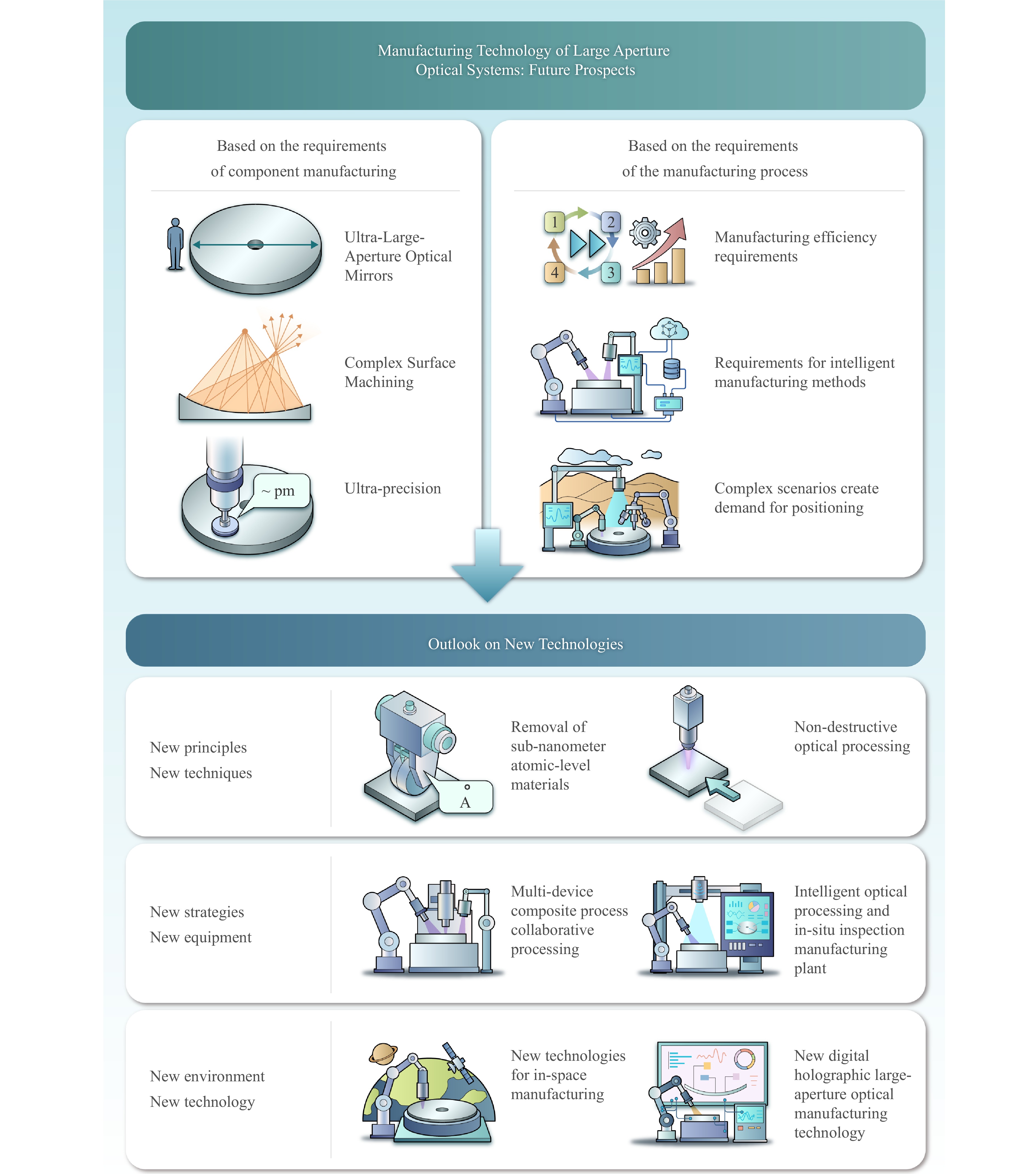
Fig. 66 A system-level framework for the future of large-aperture optical manufacturing.
-
We acknowledge the financial support of the Project supported by the State Administration for Science, Technology and Industry for National Defense (JSZL2023130B001); Project supported by Jilin Province Development and Reform Commission (2024C001); National Natural Science Foundation of China (Grant No. 62275246); National Natural Science Foundation of China (Grant No. 62305334).
Optical manufacturing and testing of large-aperture optical mirrors: a review
- Light: Advanced Manufacturing , Article number: 104 (2026)
- Received: 11 August 2025
- Revised: 18 June 2026
- Accepted: 22 June 2026 Published online: 22 August 2026
doi: https://doi.org/10.37188/lam.2026.104
Abstract: Large-aperture telescopes are indispensable tools for astronomical research. Over the past few decades, a host of representative projects have been developed, whose performance relies heavily on the manufacturing and testing technologies for large-aperture mirrors. This paper reviews the state-of-the-art fabrication and testing methods for large optical mirrors and is structured into five parts: application background, classification of manufacturing techniques, overview of metrology technologies, verification and standards, as well as conclusions and future perspectives. Sustained innovation in fabrication and testing lays a solid foundation for technological progress in this field and the implementation of next-generation telescope projects. Key development directions include achieving sub-nanometer-level surface accuracy, boosting large-batch manufacturing efficiency, upgrading metrology equipment and methodologies, and promoting the intelligent and automated integration in fabrication and metrology systems. It is expected that this review will serve as a valuable reference for researchers aiming to gain a full insight into understanding of manufacturing and testing technologies for large-aperture optical components.
Research Summary
Optical Manufacturing and Testing of Large-Aperture Optical Mirrors: A Review
Large-aperture telescopes are critical to astronomical observation, whose performance depends on the fabrication level of large-aperture optical mirrors. Zhang Xuejun, Li Longxiang and their team review full-chain manufacturing routes for representative large-aperture mirrors, covering blank preparation, deterministic polishing/figuring with full-spatial-frequency error convergence, cross-scale metrology, and acceptance testing. They summarize a closed-loop iterative paradigm in which manufacturing and testing evolve synergistically: manufacturing targets drive process requirements, while high-precision measurement enables surface-error correction. Building on this review, they outline technology prospects—sub-nanometer-level full-frequency-band precision control, intelligent adaptive manufacturing–testing integration, and space in-orbit manufacturing for future ultra-large-aperture optical mirrors.
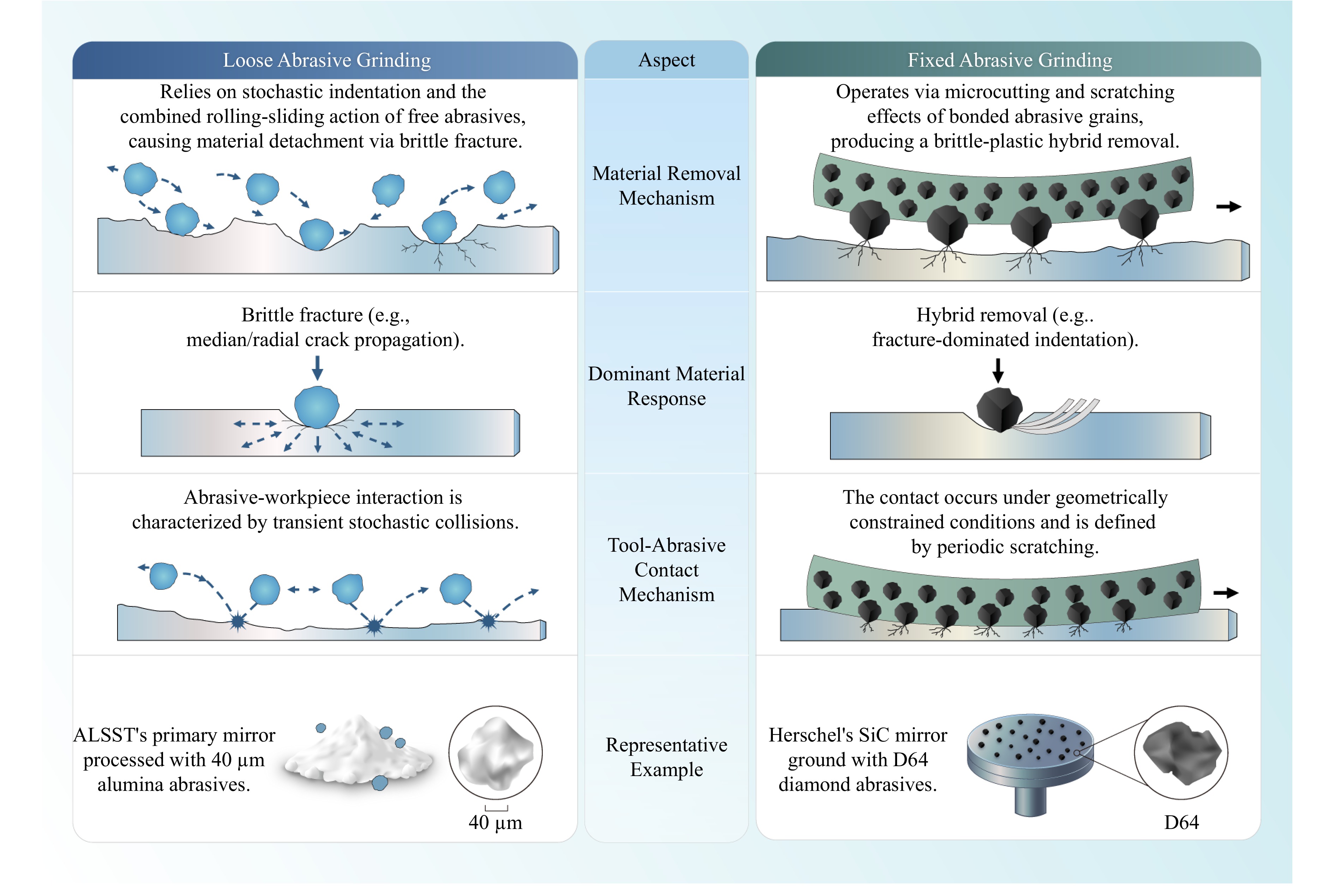
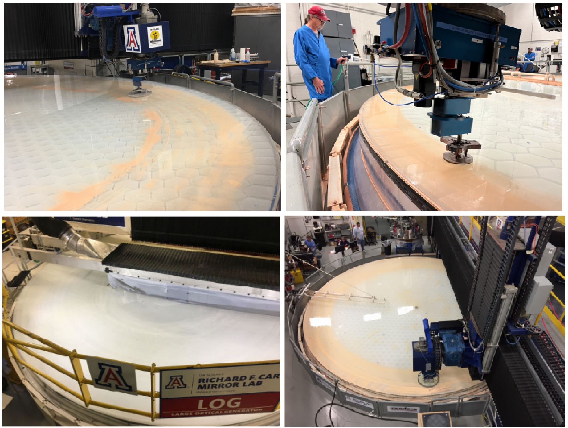
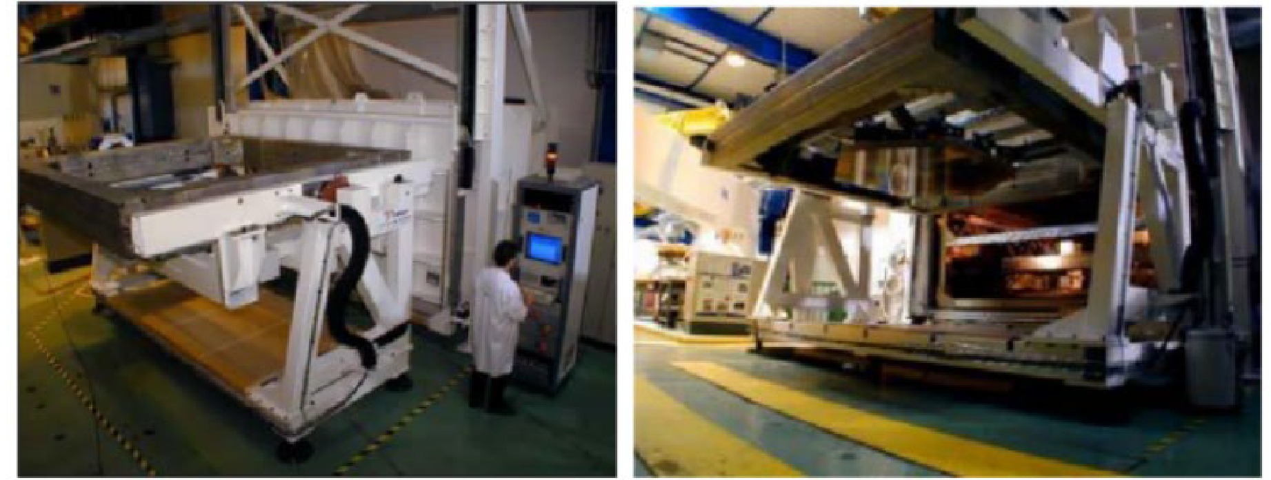
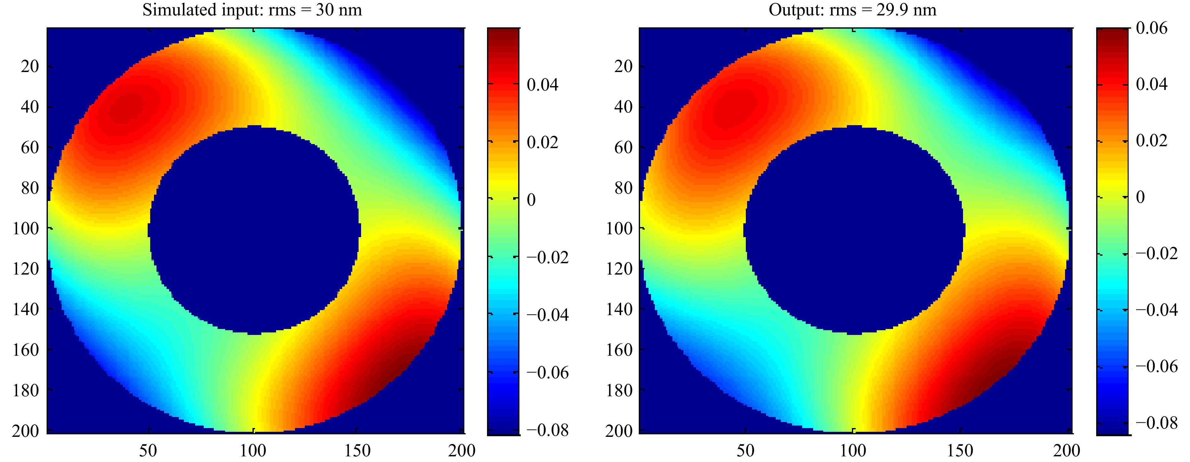
Rights and permissions
Open Access This article is licensed under a Creative Commons Attribution 4.0 International License, which permits use, sharing, adaptation, distribution and reproduction in any medium or format, as long as you give appropriate credit to the original author(s) and the source, provide a link to the Creative Commons license, and indicate if changes were made. The images or other third party material in this article are included in the article′s Creative Commons license, unless indicated otherwise in a credit line to the material. If material is not included in the article′s Creative Commons license and your intended use is not permitted by statutory regulation or exceeds the permitted use, you will need to obtain permission directly from the copyright holder. To view a copy of this license, visit http://creativecommons.org/licenses/by/4.0/.

 DownLoad: