


-
In recent decades, special attention in modern optics has been paid to studies of the terahertz region of the spectrum. After a long period, during which research in this spectral region was limited by the lack of suitable radiation sources and detectors, the emergence of broadband terahertz radiation sources based on the use of femtosecond lasers1, 2 has led to a burst of research and development of applications in this field. Most of the works used the time-domain spectroscopy technique. An advantage of this method is the possibility of simultaneous measurement of the amplitude and phase of the probe radiation, which makes it possible to implement a unique measurement method. On the other hand, this technique does not allow investigating fast (transient) processes and implementing some of the optical schemes well-known in the visible range.
The recent appearance of monochromatic sources of terahertz radiation (quantum cascade lasers3, diode lasers4, gyrotrons5 and free electron lasers6, 7), some of which have high average power, makes it possible to expand the variety of implemented optical systems in this range. Terahertz monochromatic radiation is applied to examination of the structure of materials and spectroscopy8, 9, construction of scanning and imaging systems10, biomedicine11, process materials12, creation of remote sensing systems (lidars)13 and telecommunication systems14, 15, as well as in fundamental research, for example, of a gas discharge16. In a significant part of applications8, 11−13, 16, the use of high-power terahertz radiation is required.
In contrast to the visible range, holography is one of the least developed areas of terahertz optics. A search of the Webofscience Core Collection reveals that only 0.5% of the publications related to the terahertz range are devoted to holography, most performed using time-domain spectroscopy (see, for example in Ref. 17). Only 4% of them were carried out with the use of monochromatic radiation sources (see, e. g. in Refs. 18−20).
In this review, we summarize the results of fifteen years of research in the field of holography21, carried out at the Novosibirsk free electron laser (NovoFEL)13, 22. These studies covered both digital holography (analog-to-digital conversion), that is, the holographic recording and reproduction of images of objects with subsequent registration of images with a digital camera, and computer holography (digital-to-analog conversion), that is, the conversion of wave fields using diffraction optical elements (DOEs), which played the role of computer-synthesized holograms in this case.
NovoFEL is one of the facilities of the Siberian Center for Synchrotron and Terahertz Radiation. At present, it is a source of monochromatic terahertz radiation with the highest average power, and in a routine mode, depending on the wavelength, it generates radiation with a power of 10 to 200 W. If necessary, the power can be reduced both by an electronic shutter, which blocks the generation of a given fraction of pulses in the electron accelerator, and by ordinary attenuators. The laser operates in a quasi-continuous mode with a frequency of 5.6 MHz, emitting pulses with a duration of 100 ps, which limits the coherence length in holographic measurements. The Gaussian laser beam is linearly polarized. The divergence of a beam with a profile close to Gaussian is equal to
$ 3\cdot 10^{-3} $ rad. The laser has three separate resonators, which can generate wavelength-tunable radiation in the ranges of 8−10, 40−80, and 90−340 μm. Most of the experiments were carried out at wavelengths of 130−150 μm; some experiments were carried out at other wavelengths. The lasing spectrum width is 0.3−1% of the wavelength.The important direction was the development, manufacture, research, and use of diffractive optical elements for the transformation of FEL radiation into specified light fields. DOEs were created to convert a Gaussian beam into beams of a different mode composition, as well as DOEs with the help of which the beam was focused into specified 2D and 3D regions. In the visible range, this problem is easily solved with spatial light modulators, but there are no commercially available modulators in the terahertz range. In addition, the DOEs must be resistant to the high radiation power in strong light fields. In addition to holographic applications, the development of diffractive elements of terahertz and submillimeter ranges resistant to high-power radiation is necessary, for example, for optical systems of gyrotrons5, used, in particular, for heating thermonuclear plasma23. The long wavelength enables production of DOEs using technologies that are not widely used in the optical range - laser ablation24 and 3D printing25 for the manufacture of terahertz photonic elements. Below, we present the characteristics of some DOEs investigated in experiments at NovoFEL, fabricated using original techniques.
Another important application of NovoFEL is carrying out full-scale experiments to simulate DOEs designed for operation in the short-wavelength range. The possibilities of experimentally studying the interaction of a light wave with a subwavelength 2D or 3D structure in the optical range are limited by the resolving power of micro- and nanostructuring technologies in the manufacture of DOEs. A terahertz laser with a tunable wavelength makes it possible to study the diffraction of a light wave by objects of complex topology and with a large ratio of the wavelength to the characteristic size of inhomogeneity.
-
In the terahertz range, radiation detectors are key elements in optical systems requiring image recording. In this part we present holography as an imaging technique for amplitude and phase objects. An image appears after numerical reconstruction of a digital hologram described in “Classical holography imaging” section below. Here we leave out of our scope single-channel detectors, hot-electron detectors26, and semiconductor detectors27, which can be applied to recording of holograms by scanning techniques20. All matrix detectors we employed to record terahertz images in different experiments are based on the detection of the thermal effect of radiation, but with different techniques of registration of the thermal imprint.
In more than 15 years of our research in that area28, 29, which can be called holography in the broad sense of the word, five imaging systems have been created or adapted to the terahertz range by our effort30. None of them is universal, combining high sensitivity, high spatial and temporal resolutions, as well as a large working area, which is important for achieving a high Nyquist frequency, particularly in the case of long-wavelength radiation. For this reason, the choice of recorder is determined by requirements of each particular experiment.
The recorders are shown in Fig. 1, and their characteristics are summarized in Table 1. The first three devices are not directly sensitive to terahertz radiation, and they could only register its heat trace. The very first primitive Fresnel holograms, diffraction patterns of amplitude masks with a reference hole for the reference beam28, were captured with the use of a thermal imager (TI) sensitive to near-infrared radiation. Due to the low spatial and temporal resolution of the holograms recorded in this way, as well as the strong thermal noise at the laboratory at a wavelength of 3 μm, later we used other methods.
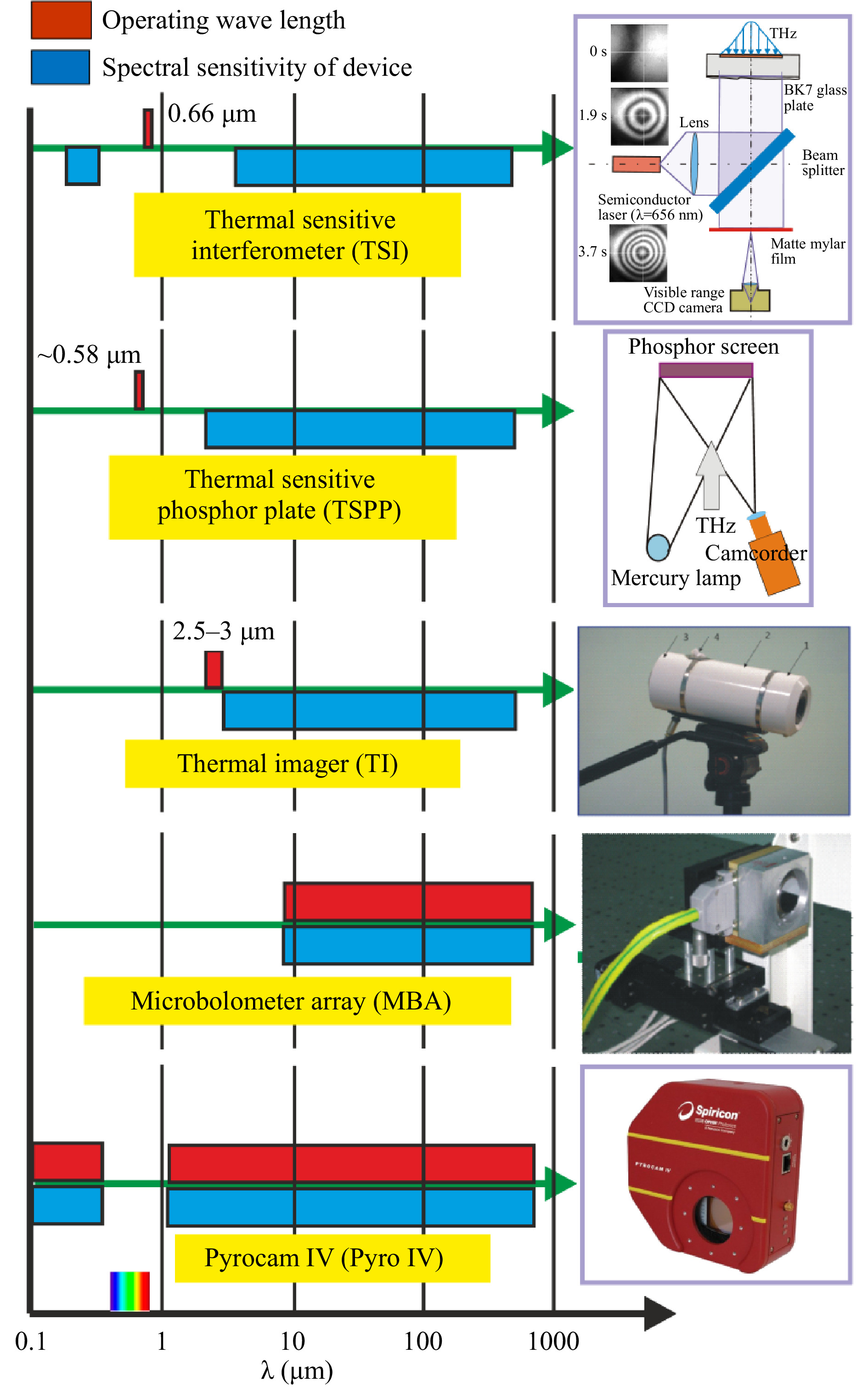
Fig. 1 Imaging devices used in terahertz range. Blue bars: ranges of spectral sensitivity of devices. Red bars: operating wavelength of final recorders.
Device TSI TSPP TI MBA Pyrocam IV Mode active active passive direct direct ∆x (mm) 0.3 0.25/1.5 2 0.051* 0.08* ∆t (s) 0.3 0.2/1.3 0.02 0.02 Repetition rate (fps) − 4/1 25 20 25 Area (mm2) 50 × 50 75 × 75 − 16.32 × 12.24 25.6 × 25.6 Sensitivity medium low medium very high high Table 1. Characteristics of imaging devices at wavelength of 140 μm (asterisk denotes pixel size)
The other two devices, in which radiation of the visible range was used for registration of terahertz images, had a higher spatial resolution. The large area of holograms obtained with their help improves the quality of their reconstruction. In a thermal sensitive interferometer (TSI), a video camera records the dynamics of an interference pattern in a plane-parallel glass plate illuminated by a collimated visible diode laser beam. The investigated terahertz radiation illuminates the plate, which is not transparent in the terahertz range, from the reverse side. The change in the refractive index in the thin glass layer due to the heating increases locally the optical path length. Since it is known a priori that when the plate is exposed to terahertz radiation after opening of the shutter, the phase incursion at each point can only be positive, the interferogram can be easily converted numerically into the intensity distribution of the terahertz beam. The thermo-optical properties of BK7 glass are standard and well known. In Ref. 31, we showed that such an interferometer is an absolute power meter. It does not require any calibration, because a shift by one fringe depends only on thermal-optical characteristics of the plate, and for K7 glass it corresponds to a locally absorbed power of 5.1 J/cm2. Unlike all other visualizers, this device is used in the single measurement mode. Re-measurement is possible only after the plate has cooled down. The possible size of the image is determined by the size of the illuminated area, which in our case was equal to 60 mm.
Another large-area recorders, eight Macken Instruments thermosensitive phosphor plates (TSPPs), were capable of recording holograms with an area of 75 by 75 mm. The principle of their operation is based on thermal quenching of luminescence excited by a mercury lamp. We have shown32 that the response to heating is linear up to a quenching value of about 50%. Table 1 shows the characteristics of plates No. 7 and No. 8.
For the first time, matrix receivers capable of directly detecting terahertz radiation in real time were used in the mid-2000s33, 34. Those were microbolometer arrays (MBAs) with vanadium oxide sensors designed for the mid-infrared range. Their sensitivity threshold in the THz range was 15 times less than that in the IR range. Nevertheless, it was rather high (
$ 10^{-3} $ W/cm2 or 33 nW/pixel). It was soon discovered that they were polarization-sensitive, and the antenna effect in the lead wires turned out to be a mechanism for absorbing terahertz radiation35. The antenna effect is now employed in newly designed microbolometer arrays36. The resolution of array receivers is restricted by the wavelength limit since the size of their sensitive elements is smaller than the wavelength. A relative disadvantage of these cameras, for example, when shooting holograms, is their small physical size. Recently, commercially available Pyrocam IV pyroelectric camera with a$ 320 \times 320 $ matrix, but with sensitivity lower than the MBA sensitivity, have appeared. Thus, at present, there is some possibility of choosing imaging devices in the terahertz range. Examples of holograms recorded by different imaging devices and reconstructed images are shown in Fig. 2.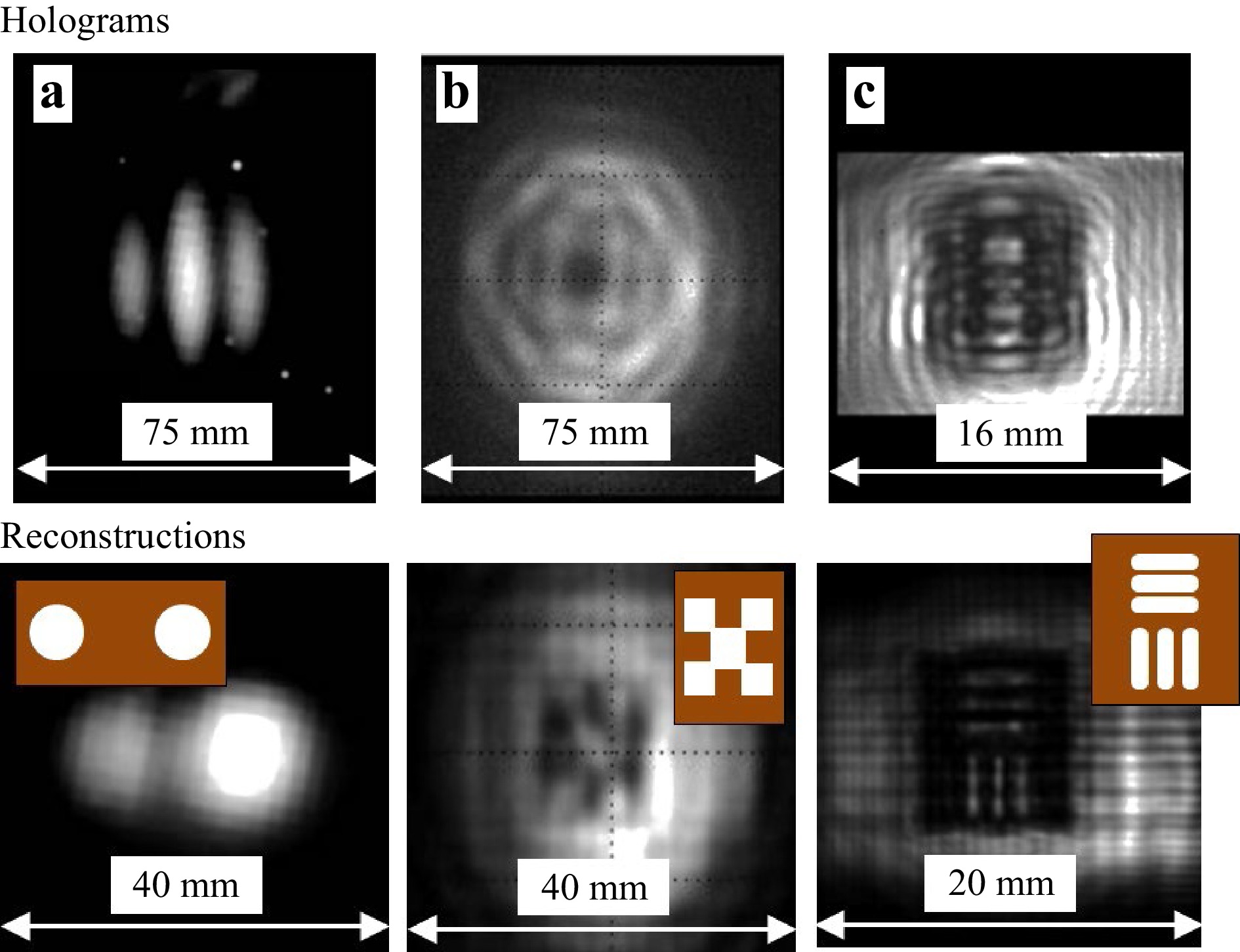
Fig. 2 Holograms (top row) recorded a by thermal imager (two circular apertures with diameter of 6 mm and spacing of 14 mm), b thermal sensitive phosphor plate, c microbolometer matrix, and respective reconstructed images (bottom row); objects (metal masks). Figure a is adapted with permission from Ref. 28; Figures b and c are adapted with permission from Ref. 29.
-
Because of the lack of media that store the intensity distribution in the THz range, holograms can be recorded only digitally, and thus they can be reconstructed either digitally or by means of a second light source (e.g. visible range laser source). There are several approaches to calculation of back propagation, overviewed in Ref. 29. We consider back propagation as the most adequate technique for image reconstruction. In the terahertz range, the pixel size to the wavelength ratio limits the applicability of reconstruction techniques. Here, given our experience with sampling limitations, we will show reconstruction using only the Rayleigh-Sommerfeld convolution (RSC) approach since it works the best with our geometries. Let us briefly recall that to perform the reconstruction numerically, one needs to multiply the hologram transmission function
$ H(\xi,\eta) $ by the complex conjugate reference wave$ E_{R}(\xi,\eta) $ in the hologram plane$ \{\xi,\eta\} $ (Fig. 3a). We used for the reconstruction a plane wave with uniform intensity,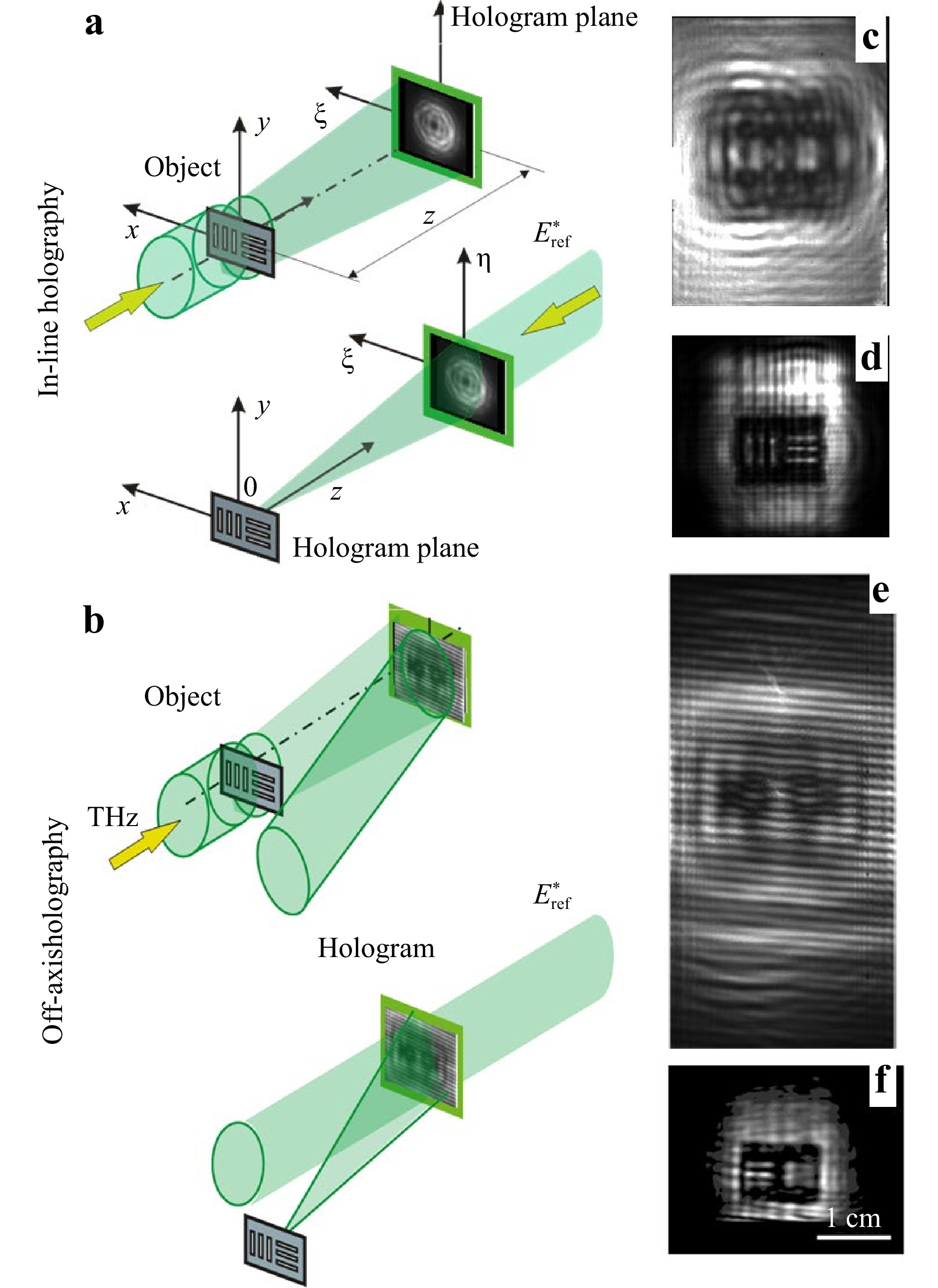
Fig. 3 Images of example object showing finest achieved resolution for inline and off-axis geometries. Recording and reconstruction schemes a, b. Holograms of metal mask c, e and reconstructed images d, f with RSC approach, for in-line and off-axis scheme respectively.
$$ E_{R}(\xi,\eta)= E_{R}^{*}(\xi,\eta)=1. $$ (1) The output wave propagates through free space in the backward direction and forms a wave field in the object plane
$ \{x,y\} $ , which is described by the Rayleigh-Sommerfeld diffraction integral$$ E(x,y)= \frac{i}{\lambda} \iint H(\xi,\eta)\frac{\exp(-ikr)}{r}\cos(\mathbf{n,r})d\xi d\eta, $$ (2) where
$ H(\xi,\eta) $ is the hologram transmission function, and λ is the wavelength. The distance$ r(\xi,\eta,x,y) $ is determined as follows:$$ r=z^{2}+(\xi-x)^{2}+(\eta-y)^{2}. $$ (3) $$ \cos(\mathbf{n,r})=z/r, $$ (4) is the reconstructed wave. Solution of Eq. 2 enables derivation of the intensity and phase distributions in the object plane using the following expressions:
$$ I(x,y) = \lvert E(x,y) \rvert^{2}, $$ (5) $$ \varphi(x,y) = \arg \frac{Im [E(x,y)]}{Re [E(x,y)]}. $$ (6) Eq. 2 can be solved directly without any approximations, or, if the experimental configuration allows, it can be simplified and solved by other methods, which include one or several (Fast) Fourier transforms. For the Fraunhofer diffraction zone (
$ z>k[(\Delta x)^{2}+(\Delta y)^{2}]_{max}/2 $ ), the hologram can be reconstructed with a single Fourier transform. Since in a real holographic experiment, the terahertz hologram is almost always located in the near zone, hereinafter we will consider only the Fresnel diffraction.By virtue of the convolution theorem and Eq. 2,
$ E(x,y) $ can be written down as$$ E(x,y) = {\cal{F}}^{-1}\{ {\cal{F}}[H(\xi, \eta)]\cdot {\cal{F}}[h(\xi, \eta))] \}, $$ (7) which is referred below to as the RSC, where
$$ h(\xi, \eta) = \frac{iz\exp(-ik\sqrt{\xi^{2}+\eta^{2}+z^{2}})}{\lambda (\xi^{2}+\eta^{2}+z^{2})} $$ (8) is the impulse response function.
Reconstruction of holographic images without aliasing requires fulfillment of the conditions of the sampling theorem. In the case of the RSC, such conditions, depending on four dimensionless parameters, were derived in Ref. 29.
The RSC approach also works for off-axis holograms recorded in the scheme of the Mach-Zehnder interferometer. To compare the off-axis and inline holography resolutions, we created an image of a target with horizontal and vertical slits of 0.6 mm (Fig. 3). For higher spatial resolution, the off-axis hologram was made of five frames by scanning in a plane perpendicular to the direction of beam propagation. It can be seen that this resolution is limited and unattainable in the absence of an expansion of the hologram recording field.
To conclude, in-line holography systems have a larger effective field of view and a higher imaging resolution as compared with off-axis ones37 for the terahertz range. However, there are systems with a strong zero order diffraction, like imaging in attenuated total reflection systems, which require using an off-axis recording technique38, 39. Besides, it should be mentioned that information about phase in an inline scheme in general can be obtained with additional phase retrieval algorithms, while off-axis holography easily provides it. At the same time, specifically to the THz frequency range, where, as it was mentioned earlier (Table 1), the pixel size can be less than the wavelength, the angles between the reference and object waves can be larger. Thus, it is possible to form subwavelength interference fringes, which will not degrade the resolution during the reconstruction, similarly, as it was done in numerical postprocessing in work Ref. 10.
-
In practical holography of the terahertz range, two main directions can be distinguished. In the first38−40, as in the optical range41, there is a real object, the amplitude-phase image of which is to be reproduced. In this case, it is necessary to use the methods of interference recording of the THz hologram of the object, described in the previous sections. On the other hand, one can pose the problem of forming a terahertz field given only by its calculated characteristics (intensity or amplitude-phase distribution). In this case, it is necessary to numerically solve the inverse problem of the theory of diffraction42, 43 with the subsequent fixation of the result on an optical material transparent in the terahertz range. At high radiation power, an additional requirement is a sufficiently high radiation resistance of the material. The approach that consists in computer synthesis of a hologram of an object, given only its calculated light distribution, is known as computer holography.
The methods of computer holography have much in common with the methods of diffractive computer optics, which is widely used for control of characteristics of coherent beams in the optical range42−44.
One of the most important characteristics of diffractive elements is their efficiency. Further, when describing a DOE, we will use two terms characterizing this quantity. By the diffraction efficiency (DE) of element we mean the passed radiation energy fraction that is involved in the formation of the given (desired) light distribution. The energy efficiency (EE) of element is the incident beam energy fraction that produces the given distribution. Accordingly, the energy efficiency takes into account the Fresnel reflection, absorption, and scattering.
-
In the terahertz range, there are several approaches to diffractive optics manufacturing: polymer lenses, which demonstrate low absorption and are fabricated by mechanical milling45, 3D printing46, imprinting with a silicon master47 or by hot pressing48. However, an intense radiation field can damage these elements30. High-resistivity silicon or diamond is more resistant49, which is especially important for high power radiation. We will show by the example of diffractive lens (DL) how silicon and diamond diffractive optical elements can be manufactured. DLs (spherical and cylindrical ones) are a promising alternative to commercially available refractive lenses and reflective metal mirrors50, since they are typically much thinner and have lower weight.
Binary and multilevel51 silicon DLs have been fabricated via the technology of lithography. A binary DOE micro-relief fabricated on the surface of high-resistive silicon substrate via single reactive ion etching technology (Bosch process) is considered in Ref. 52. The Bosch process in an inductively coupled plasma source configuration (ICP–RIE)52 in an atmosphere of C4F8/Ar (passivation) and SF6/Ar (etching) was used. To decrease the Fresnel losses after fabrication of diffractive microrelief, the double-sided antireflection coating of Parylene C52 has been applied. Binary elements are made for a certain wavelength, for example, for
$ \lambda = 141 $ μm; the micro-relief height is$ h=29.1 $ μm, and the silicon refractive index is$ n = 3.42 $ . (Fig. 4a). Binary lenses are easier to make, but they have limited diffraction efficiency (a theoretical estimation of binary Fresnel lens diffractive efficiency is 41%42). Losses due to the Fresnel reflection at the “silicon-air” interfaces can be reduced with application of double-sided antireflection coating of Parylene C52.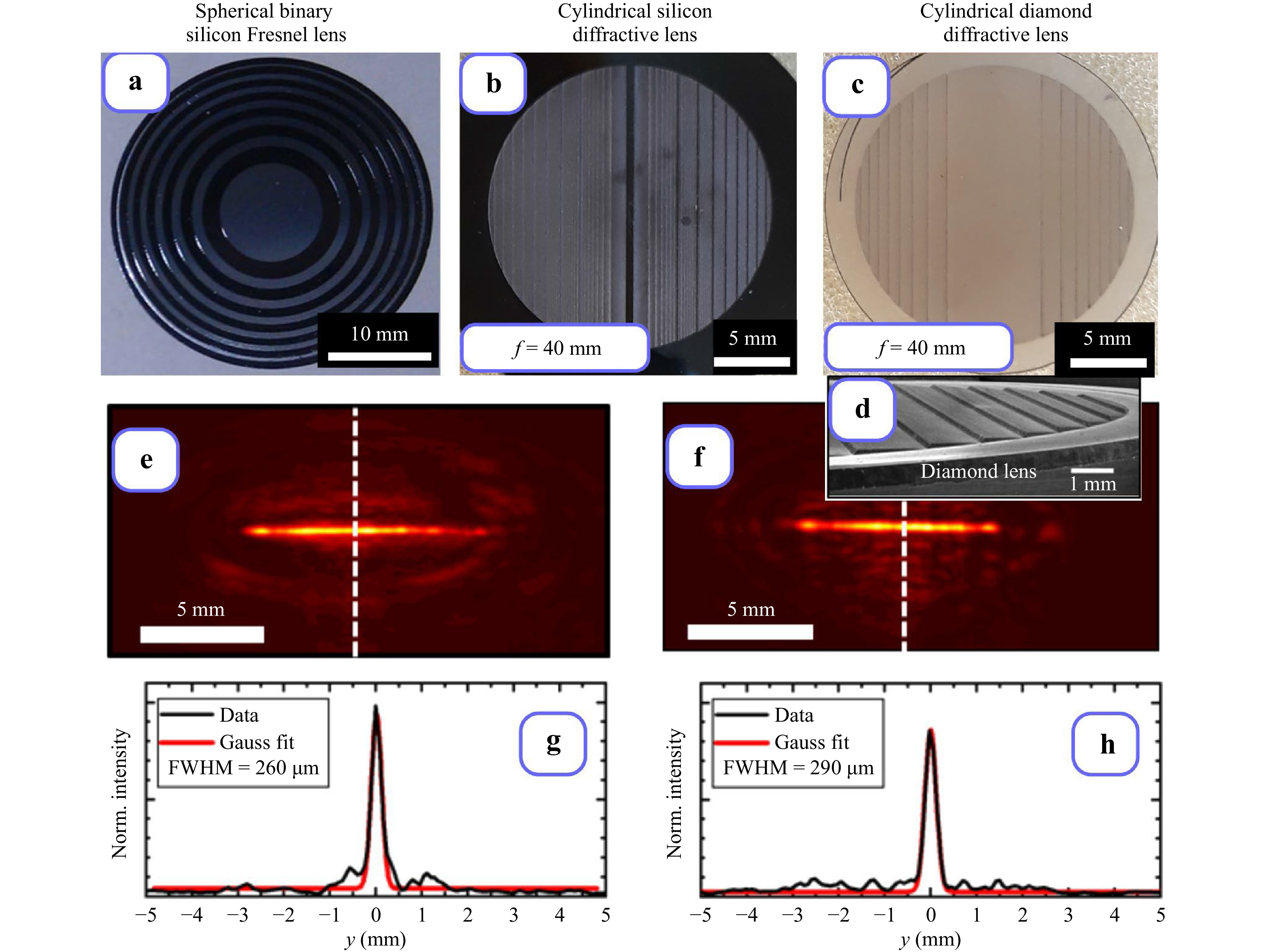
Fig. 4 Diffractive lenses designed for
$ \lambda=141 $ μm: silicon binary spherical Fresnel lens a, silicon cylindrical diffractive lens with continuous profile b, diamond cylindrical diffractive lens with continuous profile c, d. Intensity distributions in focal planes of silicon e, g and diamond f, h lenses, respectively.The laser ablation technology developed at GPI RAS has been first applied to creation of a silicon Fresnel lens with four-level relief 53. The laser ablation process in Ref. 53 was based on the use of femtosecond Yb:YAG laser. Later the laser ablation technology has been further improved for fabrication of lenses continuous relief (Fig. 4b)24. A multimode laser system (VaryDisk50 from Dausinger + Giesen GmbH, Germany) generating 1 ps pulses at a wavelength of 1030 nm has been used for fabrication of continuous relief by laser ablation in Ref. 24. The measured diffractive efficiency of silicon diffractive cylindrical lens with continuous relief was 93%24.
Diamond films (DFs) is another promising optical material for high-power terahertz application54. The thermal conductivity of DF is larger than the thermal conductivity of silicon; a DF has a smaller refractive index (
$ n = 2.4 $ ), and therefore diamond optical elements have lower Fresnel losses. Fabrication of infrared diamond lenses by laser ablation are described in Ref. 55. The technology of terahertz diffractive microrelief fabrication by laser structuring of silicon surface56 with subsequent diamond film chemical vapour deposition (CVD) on the structured silicon surface was proposed first in Ref. 57. The silicon substrate was removed after diamond film deposition. A THz diamond cylindrical diffractive lens with continuous relief was fabricated (Fig. 4c). The intensity distribution measured in the focal plane of the fabricated cylindrical lenses is presented in Figs. 4e−h. The measured diffractive efficiency of the diamond diffractive cylindrical lens with continuous relief was 95%57. -
A number of applications (THz range imaging and radioscopy58, soft-tissue ablation11, material processing12, etc.) require focusing of THz range radiation into pre-given 2D areas. The formation of uniform intensity distribution in the THz range will allow us to use THz ablation more effectively, give up point-by-point scanning, and develop a new generation of laser beam scanners.
Results of focusing a THz laser Gaussian beam into a square area with uniform intensity distribution are presented in Fig. 559. The binary two-level microrelief of the element shown in Fig. 5a was calculated by a stochastic procedure42 with the following parameters: the aperture size
$ D=30 $ mm; the wavelength$ \lambda =141 $ μm; the focal length$ f=368 $ mm; the radius of the incident Gaussian beam$ w=9 $ mm; the square focal area size$ a=8.6 $ mm. The calculated diffractive efficiency of the element was$ e = 55.6 $ %.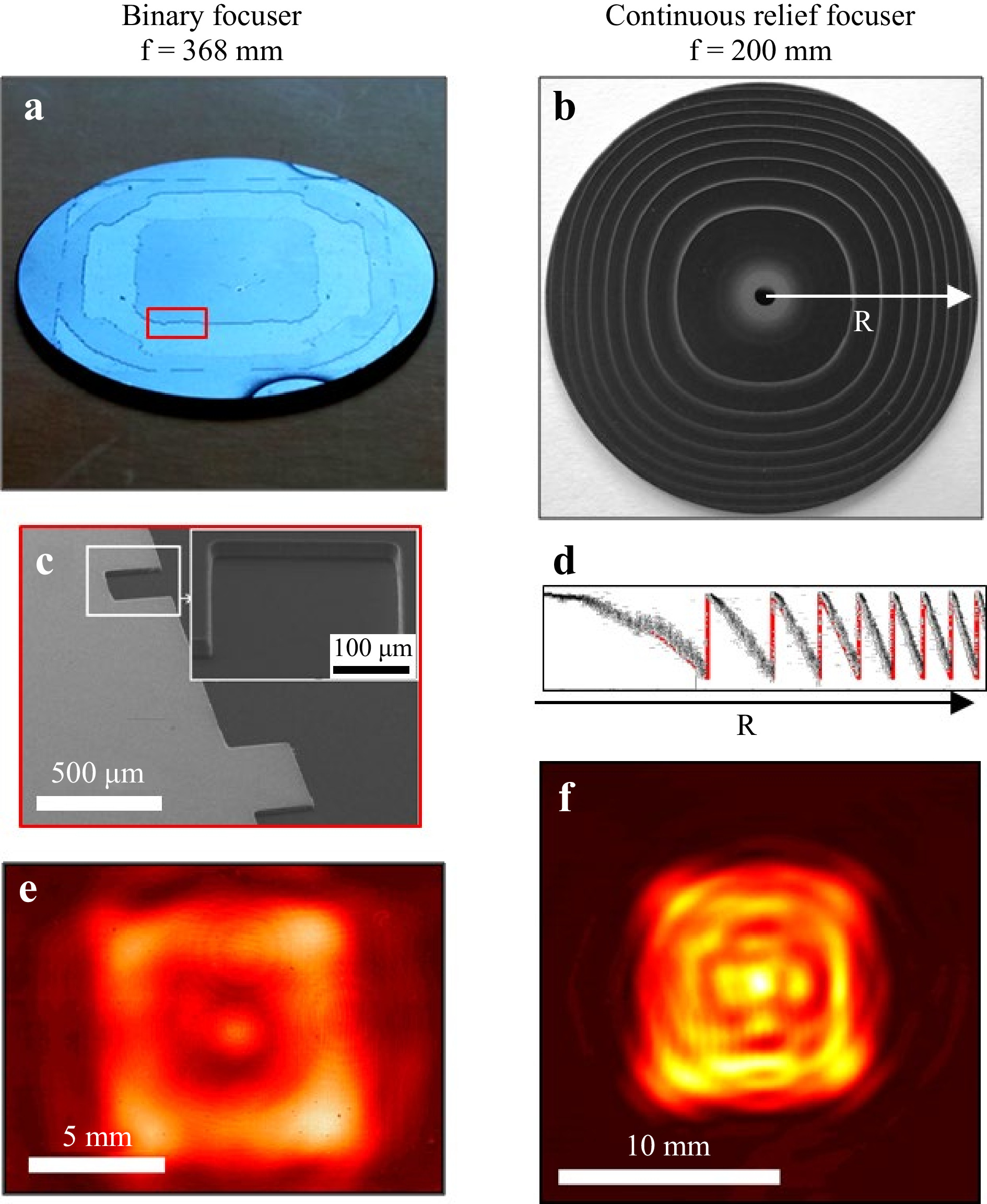
Fig. 5 Silicon DOEs with binary a and continuous b61 microrelief focusing Gaussian beam into square. c Binary microrelief recorded by electron microscopy. d Profile of continuous microrelief measured with white light interferometry (black plot) and simulated profile (red line). Intensity distributions in focal plane of silicon focusing DOEs with binary microrelief e and with continuous microrelief f.
A binary micro-relief (Fig. 5c) was fabricated via single reactive ion etching of silicon with subsequent application of a double-sided antireflection coating of Parylene C. The experiment has shown strong dependence of the element performance on the deviation of the illuminating beam mode radius value from the estimated one. The intensity distribution in the focal plane of the element is shown in Fig. 5e.
A DOE with a continuous profile (Fig. 5b, d) for focusing a Gaussian beam into a square-shaped region was designed with the ray optics approach60. This DOE was fabricated by means of the technology of laser ablation. The element was calculated for the wavelength
$ \lambda = 130 $ μm and had the focal length$ f = 200 $ mm. The intensity distribution in the DOE focal plane is presented in Fig. 5f. The measured diffraction efficiency of the element61 was equal to$ (97 \pm 2)\% $ .Practical applications, such as terahertz 3D scanning and imaging (including elongated objects), ablation, optical discharge generation, etc., require focusing of terahertz radiation, often with a large focal depth. In Ref. 62, the results of studies of a silicon binary DOE intended for focusing a Gaussian beam into a paraxial segment are presented. The binary phase function of the element was calculated by a stochastic procedure63 modification based on a genetic algorithm. The calculated paraxial segment length was
$ z=30 $ mm, and the DOE efficiency$ e = 19.3 $ % in average varied in narrow boundaries for different paraxial segment cross-sections. With antireflection coating, the energy efficiency values measured in different planes during the experiment were in the range of 17.4−18.6%. The “self-reproduction” of the focused Gaussian beam during its propagation along the paraxial segment is worth noting62. The application of the fabricated optical element enabled the formation of the paraxial intensity distribution in the given space boundaries of 110 mm to 140 mm. -
The appearance of powerful terahertz gyrotrons and their modifications opens up the possibility of creating terahertz lidar systems and communication systems in free space64, 65. Investigation of the propagation of high-power terahertz beams with different transverse structures in inhomogeneous media at the Novosibirsk variable-wavelength free electron laser makes it possible to carry out full-scale modeling and optimization of such systems. For sources like free electron laser it, is nearly impossible to tune to higher modes inside an optical resonator.
Computer-synthesized holograms were proposed to form single-mode Gauss-Laguerre and Gauss-Hermite beams from an illuminating laser beam in the visible or infrared range66, 67. For reduction of complex transmission function to a pure phase or purely amplitude form, coding methods based on the introduction of a modulated carrier into the phase (amplitude) of a digital hologram were applied. However, this approach led to a low diffraction efficiency of the hologram, which was associated with the emergence of a large number of higher diffraction orders. As shown in Ref. 42, in the case of low-order Gauss-Hermite modes, a transparent element the phase function of which is the portrait of the mode to form enables creation of a beam with a required mode content of more than 80% when the element is illuminated with a Gaussian beam.
This approach was used in Ref. 68 for production of elements intended for the formation of single-mode Gauss-Hermite beams from an illuminating beam of a high-power terahertz laser. Since the phase function of the Gauss-Hermite mode over the entire cross-section area of the beam takes one of two values, that differ by π (Fig. 6), the corresponding element will have a binary microrelief, created in Ref. 68 by the technology of single reactive ion etching (Bosch process) of the surface of a silicon substrate. This method was previously used in Ref. 52.
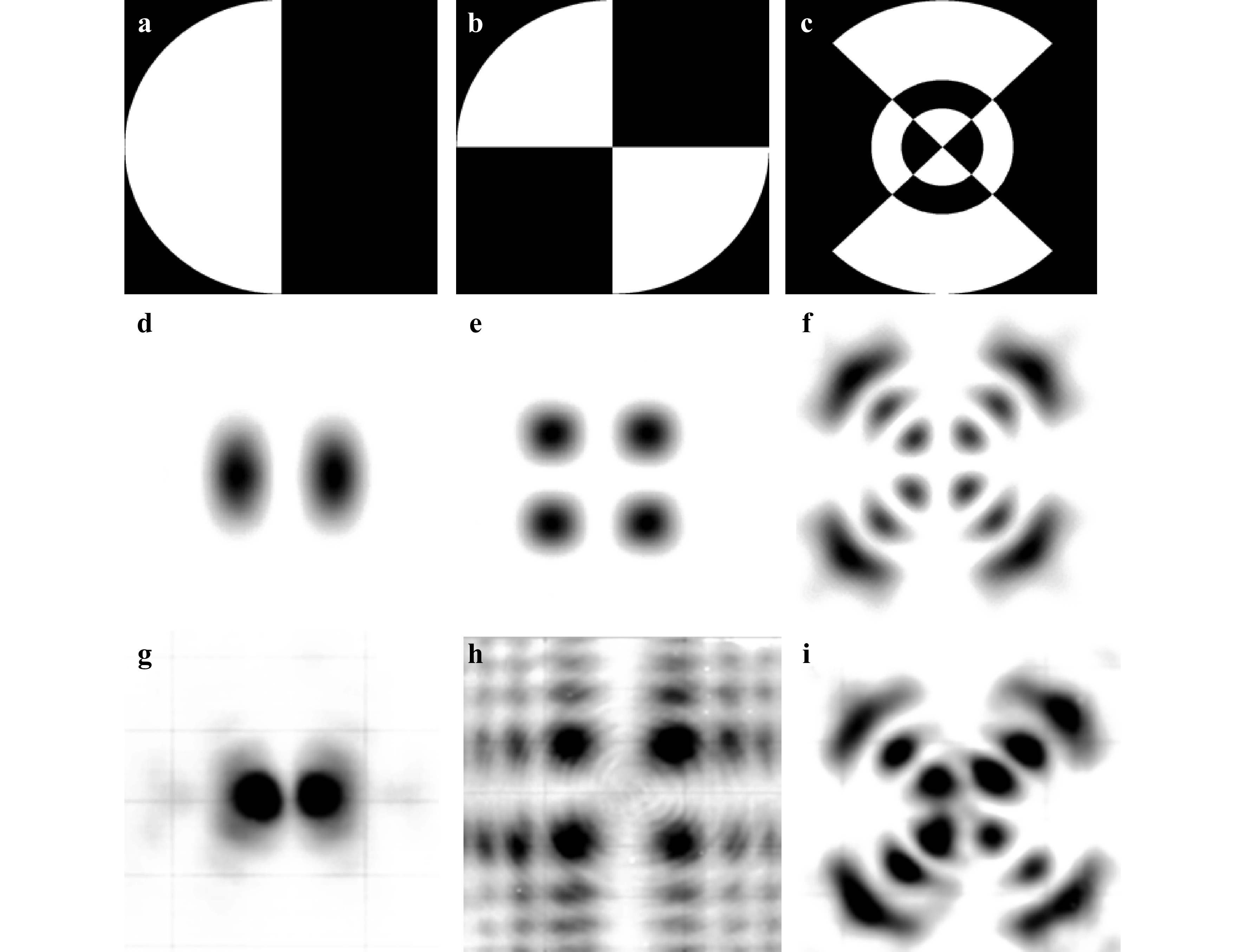
Fig. 6 Phase functions of DOEs generating Gauss-Hermite (1,0) beam a, Gauss-Hermite (1,1) beam b, beam consisting of the sum of Gauss-Laguerre modes (2,2) and (2,-2) with equal weights c (black colour corresponds to phase of 0 and white colour corresponds to π); intensity distributions d−f in cross-sections of beams generated by DOEs with phase functions a−c respectively, as result of computer simulation; intensity distributions g−i in cross-sections of beams generated by DOEs with phase functions a−c respectively, as result of natural experiment.
Fig. 6a shows the phase of the element manufactured in Ref. 68, intended for the formation of the Gauss-Hermite mode (1,0) (white color: phase value of π, black color : of 0). The intensity of the beam formed by the manufactured element in the focal plane of a TPX lens installed directly behind the element is shown in Fig. 6d for simulation and in Fig. 6g for the experiment. Figs. 6b, e, and h show similar results of a study of a silicon binary element68, which forms a single-mode Gauss-Hermite beam (1,1). Fig. 6b shows the phase function of the element, and Fig. 6h depicts the intensity of the beam formed by the manufactured element68, at the focal distance.
It is known that the use of diffractive optical elements (computer-synthesized holograms) makes it possible to obtain beams of gas, semiconductor and solid-state lasers with a given composition of transverse modes at a wavelength corresponding to one of the longitudinal laser modes42. DOEs, the manufacturing methods of which are described in Ref. 68, enable formation of beams of coherent radiation with a given transverse-mode composition in the terahertz range. An important property of NovoFEL for various experiments is the ability to tune its wavelength over a wide range69, whereas DOEs with continuous relief and binary DOEs are calculated to operate at a given wavelength. In our studies, we have successfully used various phase elements calculated for the wavelength
$ \lambda=141 $ μm in experiments performed at wavelengths$ \lambda/(2m-1) $ , in particular, at$ \lambda/3=47 $ μm. We also experimentally demonstrated that diffractive elements, for example, helical binary axicons, are capable of forming a given transverse mode composition even when the wavelength deviates from the calculated one by 25−30%. In this case, the main unwanted mode is the zero-order diffraction, which can be easily filtered out. -
Light beams with a topological charge are considered in reviews70, 71. In Ref. 42, computer-synthesized holograms were applied to form beams with a topological charge (“vortex beams”) of the visible and infrared ranges. For calculation of binary diffractive optical elements that form a terahertz Bessel beam with a topological charge, the same approach has been applied as in Refs. 72−74. The phase function of the element is described by the formula
$$ \Phi(r,\phi)=(\pi/2){\rm{sign}}(\sin(l\phi-\kappa r)), $$ (9) where
$p=2\pi/\kappa $ is the period.The element forms a beam, which amplitude is described by the Bessel function of the first kind:
$$ E(r,\phi, z, t) =E_0 J_{\lvert l \rvert} (k_r r)\exp [{i(l\phi + k_{z}z-\omega t)]}, $$ (10) where
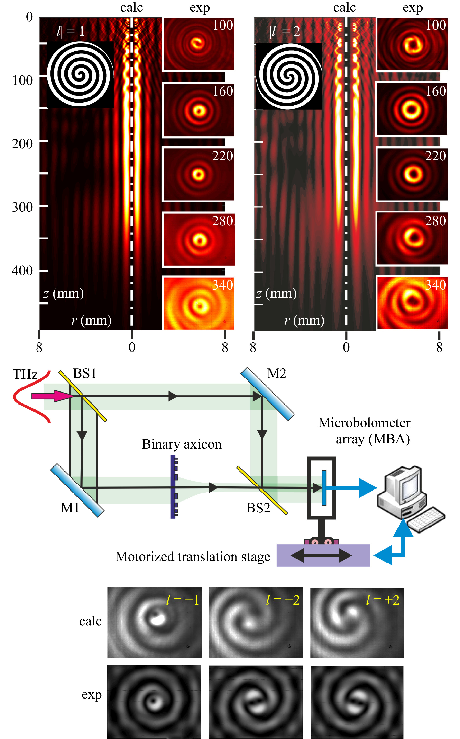
$ E_{0} $ is the maximum amplitude of oscillations, ϕ is the azimuthal angle, ω is the cyclic frequency of oscillations, k is the wavenumber, z is the distance from the source to the object, and l is a positive or negative integer, called the topological charge, which determines the degree of “twisting” of the beam.Longitudinal and cross sections of beams with orbital angular momentum formed from a NovoFEL Gaussian beam by binary spiral axicons are shown in Fig. 7. The phase relief of the axicons is shown in the insets (black colour corresponds to a phase of 0, and white colour corresponds to π). Cross-sections of the beams can be described well by the square of the Bessel function of the first kind
$ \left( J_{\lvert l \rvert}(k_{r}r) \right)^{2} $ with the topological charges$ l = 1 $ and$ l = 2 $ . The intensity distribution in the cross-section maintains within a distance of about 180 mm, after which, due to the limited aperture of the axicons, it begins to diverge. Therefore, the beams can be considered “diffraction-free”. The formed beam had an annular structure with the diameters of the rings increasing with the topological charge. The value and sign of the beam topological charge can be detected with the Mach-Zehnder interferometer shown in the bottom of the figure. This scheme is, in fact, a holographic one. -
In the optical range, the use of software-controlled spatial optical modulators makes it possible to assemble sophisticated optical systems. In the terahertz range, especially in the case of high power radiation, it is necessary to use computer-synthesized holograms (DOEs). The lateral feature sizes of the structures are large enough, and it is not necessary to use high-resolution lithographical masks. In this section, we will give several examples of using DOEs to form beams in solving several applied problems.
-
The previous sections of this article present the results of manufacture and study of binary silicon elements intended for the formation of single-mode Gauss-Hermite beams68, as well as single-mode Bessel beams with orbital angular momentum (or “vortex beams”)75, 76 of high-power coherent terahertz radiation. The creation of such elements made it possible to obtain new experimental results on the propagation of rotating (diffraction-free) beams in homogeneous75 and inhomogeneous77 media (which is important for telecommunication and lidar applications78), as well as in the study of the possibility of constructing multichannel systems for information transmission in free space of the terahertz range with transverse-mode channel multiplexing79.
Typical results of experiments to study self-recovery of beams with orbital angular momentum in free space after their passing through an inhomogeneous medium77 are shown in Fig. 8. Figs. 8a−c show the intensity distributions of the Bessel vortex beam80 formed by this element, the Bessel beam after passing through a slab of foamed polyethylene, as well as after propagation of this beam in free space at a distance of 100 mm from the film, respectively. The radiation wavelength was 141 μm. Comparing Fig. 8b, c, one can conclude that terahertz Bessel beams with orbital angular momenta are self-healing after passing through an inhomogeneous medium.
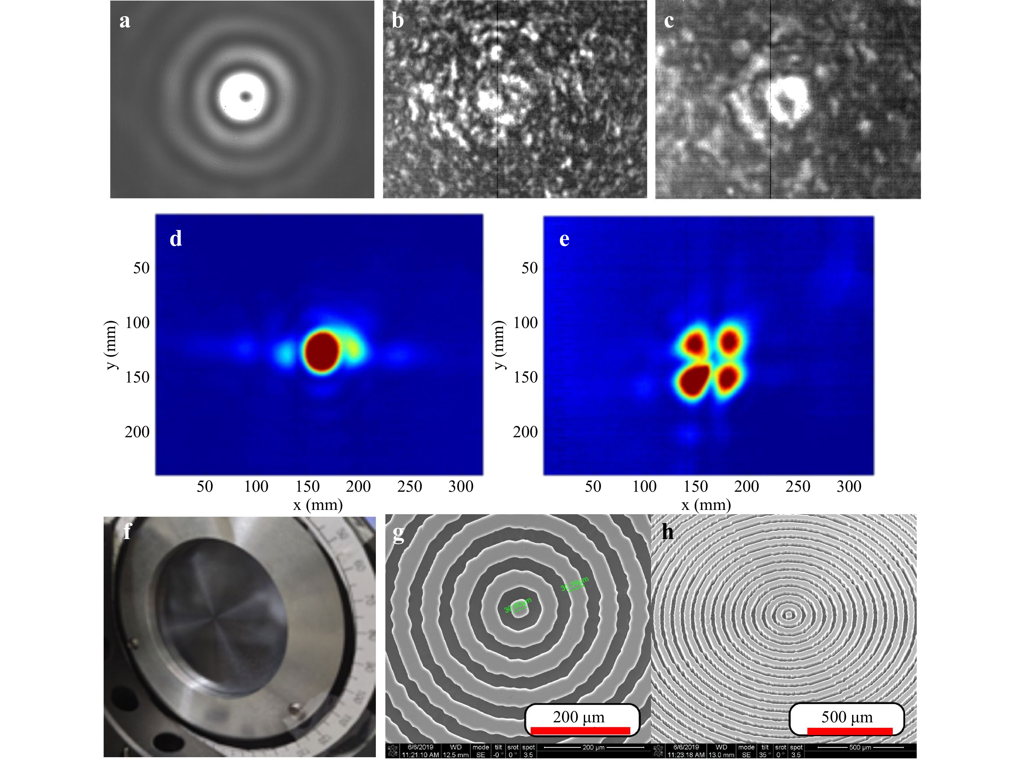
Fig. 8 Bessel vortex beam formed by DOE a, disturbed Bessel beam after passing through slab of foamed polyethylene b, disturbed Bessel beam after propagating in free space at distance of 100 mm from slab c, measured intensity distribution in output plane of correlator corresponding to presence of pre-given mode in illuminating beam d, measured intensity distribution in output plane of correlator corresponding to absence of pre-given mode illuminating beam e, fabricated subwavelength axicon f, and central fragments of axicon microrelief measured by a scanning electron microscope g, h.
In Refs. 66, 81 an approach to multiplexing channels in the optical range, based on selective power control of individual transverse waveguide modes, Mode Division Multiplexing (MDM), is considered. In Ref. 66, it was proposed to use DOEs for the formation of individual mode beams and analysis of the transverse-mode composition of waveguide radiation in the problem of constructing an MDM in the optical range. Paper79 presents the results of a study of a full-scale model of a two-channel communication system in the free space of the terahertz range (wavelength
$ \lambda = 141 $ μm). Single-mode Gauss-Hermite (1, 0) and Gauss-Hermite (0, 1) beams were used as carriers of individual channels formed by the elements68. For determination of the presence of one of these modes in the output beam, a silicon binary element matched to a given mode (correlation filter) was used79. The element was designed via the approach previously applied in Ref. 66 for optical range. Fig. 8d shows the intensity distribution in the correlation field of this element in the case of presence of a given mode in the beam. The correlation peak is clearly visible in the center of the image. Fig. 8e shows the intensity distribution in the correlation field of this element in the absence of a given mode in the beam. Thus, the creation of diffractive optical elements that make it possible to control the transverse-mode composition of the terahertz laser beam enables creation of multichannel systems in the terahertz range for information transmission in free space with transverse-mode multiplexing.Papers75, 76 were devoted to control of the transverse-mode composition of beam without change in its polarization state. However, a significant part of actual lidar and telecommunication applications78 requires formation of beams with a given transverse-mode composition and polarization state. Work82 describes the manufacture and study of a silicon element (subwavelength axicon) to form from a linearly polarized Gaussian beam of a terahertz laser (operating wavelength
$ \lambda = 129 $ μm) a beam with an intensity distribution close to that of Bessel beam, with radial polarization order 2. The element (Fig. 8f) was manufactured by the technology of single reactive-ion etching (RIE) of the silicon surface (Bosch process). Electron microscopy images of the central fragment of the manufactured element are presented in Fig. 8g, h. The results of an experimental study of the manufactured element are in good agreement with theoretical expectations and the results of computer simulation82. Thus, the creation of subwavelength terahertz elements makes it possible to form beams with a given transverse-mode composition and polarization state. -
It has long been known83 that periodic amplitude gratings are the simplest diffractive optical elements behind which when the grating is illuminated by a plane wave, images of the grating and its higher orders are formed in the Talbot planes. The position of the Talbot planes is described by the formula
$ z(j,\nu ,u) = {Z_T}(j + u/\nu) $ , where j is the number of the main plane, ν is an integer, u is a natural number$ ( u< \nu ) $ , and$ {Z_T} = 2{p^2}/\lambda $ is the Talbot distance. The diameter of the images of openings is equal in both the principal and fractional Talbot planes, but the period of the grating image in the fractional planes is a fraction of the grating period. The Talbot effect is used in numerous applications including advanced lighting systems, metrology, and more. The modern theory of the effect was developed in a series of works84−87. An overview of the current state of research can be found in Ref. 88.In work Ref. 80, we first studied experimentally the diffraction of vortex Bessel beams89 by two-dimensional periodic gratings. It was found that behind the grating, in the same Talbot planes and with the same spatial frequency, periodic distributions of the wavefield were formed, but instead of images of holes, rings were observed with the same topological charge as that of the illuminating beam.
The theory of the Talbot effect under the illumination of gratings with Bessel beams of arbitrary order was developed in our paper90. It was shown, in particular, that zero-order beams also created ring structures. The radii of the formed rings depend, in addition to the parameters mentioned above, on the transverse wave number of the Bessel beam κ:
$ \rho = (\kappa {p^2}/\pi )(j + u/v) $ . Experiments were carried out on linearly polarized Bessel beams of orders from 0 to 2. Fig. 9 shows the images observed in several Talbot planes behind the gratings illuminated by Gaussian beam and Bessel beams of the first order. It is interesting that the calculated pattern is observed even for gratings with a hole diameter of only two wavelengths (see the last column of the images, for which the opening diameters were equal to 250 μm). The amplitude and phase in the experimentally observed arrays of the vortex beamlets well agreed with the theory. Recently, similar experiments in the visible range and corresponding theoretical calculations were published in papers91, 92. The results obtained in these papers are close to our results.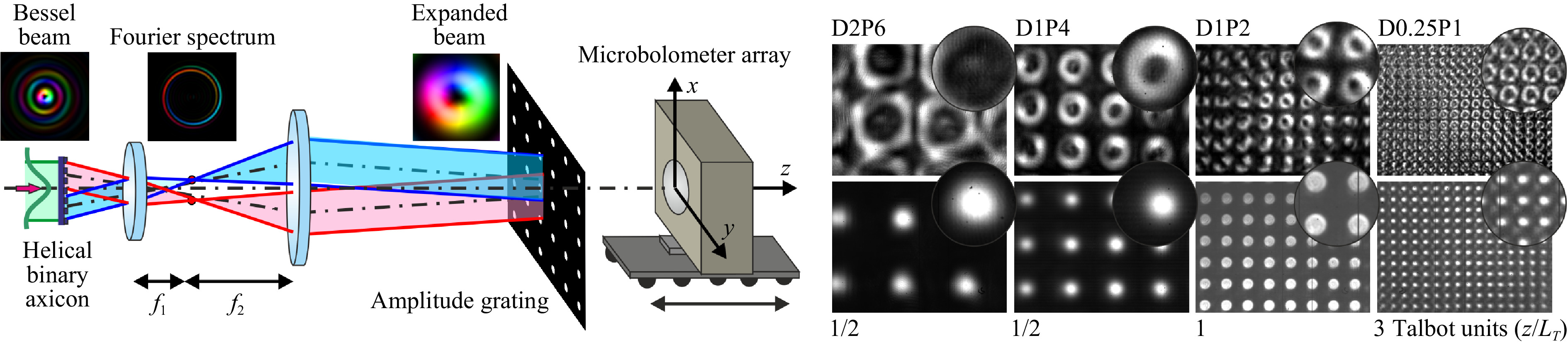
Fig. 9 Talbot effect. Principal optical scheme and images recorded with the microbolometer array in main and fractional Talbot planes80. Gratings were illuminated with Gaussian beam (low row) and Bessel beam of the first order (upper row) at a wavelength of 141 μm;
$ f_2 / f_1 =4.5 $ . Phase distribution is shown with artificial colors from$ \phi=0 $ (blue) to$ \phi=2\pi $ (red). DxPy is diameter of openings and grating period in mm. Frame size of MBA is$ 16.32\;\times\; 12.24 $ mm2.Thus, the use of spiral axicons to modify the classical optical experiment yielded a new physical effect.
-
Vortex beams, such as those described in “Bessel beams” section, have numerous applications, but in some cases, it becomes necessary to specify a special spatially-inhomogeneous polarization distribution over the beam cross-section. Such beams are called vector beams93, 94. They usually have at least one singularity. Beams with spatially inhomogeneous phase and polarization distributions are called vector vortex beams. In this section, we will describe a technique for the generation of vector vortex beams in the terahertz range.
In the experiments, we used binary spiral axicons of 50 mm in diameter, which created Bessel beams with topological charges 3 and 9. The phase relief of the axicon producing a beam with topological charge
$ l = -9 $ is shown in Fig. 10a. The sign of the topological charge of the beams can be changed by rotation of the axicon about th vertical axis by$ 180^{\circ} $ . At illumination with a linearly polarized Gaussian beam of the NovoFEL (Fig. 10d), the Bessel beam was formed at a distance of 120 mm behind the axicon. The simulated intensity distribution of the beam is shown in Fig. 10b. The beam phase distribution is shown with artificial colors on the intensity distribution. The intensity distribution over the beam cross-section, obtained in the experiment (Fig. 10f), was in good agreement with the theoretical one.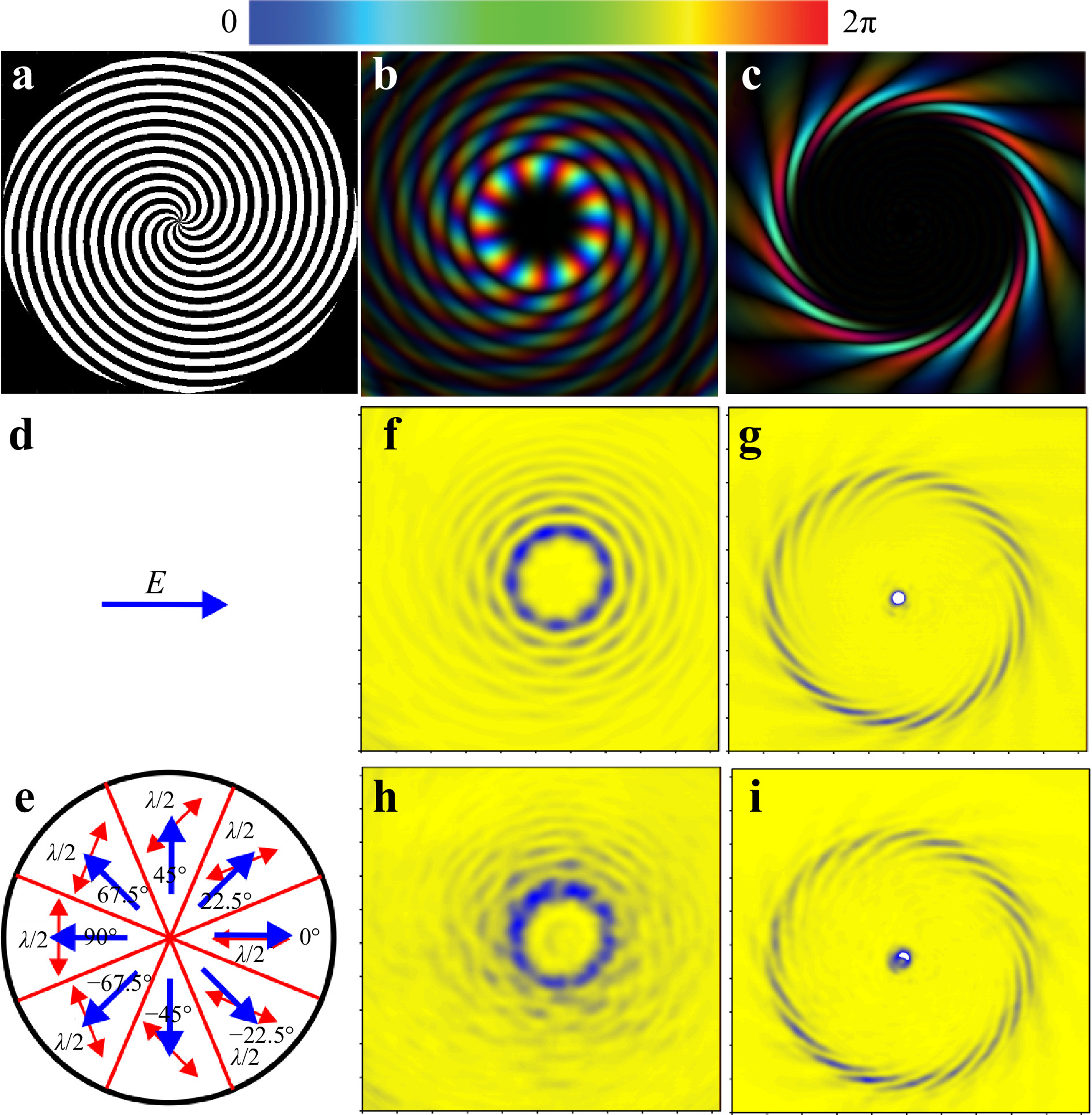
Fig. 10 Formation of vector vortex beams with topological charge
$ l=-9 $ using binary spiral axicon89. a Spiral axicon. b, c Intensity and phase distribution of Bessel beam formed by axicon and its Fourier transform (the latter is also called “perfect beam”). d Polarization of NovoFEL beam,$ \lambda = 141 $ μm. e Polarization of laser beam passed through segmented half-wave plate; red arrows: optical axis directions. f, g Bessel and perfect beams obtained using linearly polarized radiation; h, i the same with radially polarized radiation. Frame size in f–i is$ 25.6 \;\times\; 25.6 $ mm2.To obtain а Bessel vector beam, a segmented half-wave plate95, consisting of eight sectors of a birefringent crystal, was installed in 50 mm in front of the axicon (Fig. 10e). The optical axis of each next sector is rotated by an angle of 22.5°. This plate is essentially a discrete version of the half-wave q-plate96−98 with the distribution of local optical axes of
$ \alpha(r,\varphi)=q\varphi+\alpha_0 $ , which is commonly used to convert a circularly polarized beam into a beam with an orbital angular momentum. In our case, the plate, which was an analog of a q-plate with$ q=1/2 $ and$ \alpha_0=0 $ , was illuminated by horizontally or vertically linearly polarized radiation, which made it possible to obtain, respectively, a radially or azimuthally polarized beam, while its orbital angular momentum was conserved. The intensity distribution in the Bessel beam (Fig. 10h) shows eight discontinuities, which apparently appeared on the lines of gluing of the plate segments. However, the cross-section of the beam did not change significantly.The fact that the Bessel mode is largely conserved becomes clear when the Fourier image of the beam is obtained via its focusing with a high-resistance silicon lens. Experimentally obtained images in the focal plane of a lens with a focal length of 150 mm are shown in Fig. 10g for linearly polarized beams and in Fig. 10i for radially polarized beams. The simulated beam is shown in Fig. 10c. Beams created in this way are called “perfect” beams99. Their practical significance is determined by the fact that for Bessel beams with the same value of the transverse wave number, the diameters of the rings formed by the lenses are the same for any values of the topological charge. In the case of an ideal Bessel beam, non-existent in the real world, an annular intensity distribution will be observed in the focal plane. A Bessel beam created by binary axicon and its Fourier transform differ from ideal ones. In work Ref. 89, this is shown for three types of diffractive axicons: binary and with continuous phase distributions. In particular, in the case of a binary axicon, a perfect beam is a collection of
$ 2\left | l \right| $ short spirals located along the ring100. In our case, it can be seen that even the “damage” to a Bessel beam by a segmented waveplate practically does not change the perfect beam. -
An example of the use of perfect beams is the demonstration of the generation of terahertz surface plasmon polaritons (SPPs) with orbital angular momentum on an axisymmetric, singly connected transmission line101, 102. This approach is a first pace to the development of multiplex plasmonic transmission lines in the terahertz range103. The experimental setup is shown in Fig. 11. The input optical system enables formation of vortex perfect beams with
$ |l| = 3 $ or 9 with radial and azimuthal polarizations. The annual beam radii were equal to the input diameter of the cylindrical line. Plasmons on the cylinder were excited by diffraction of a perfect beam on the front edge (end-fire coupling technique).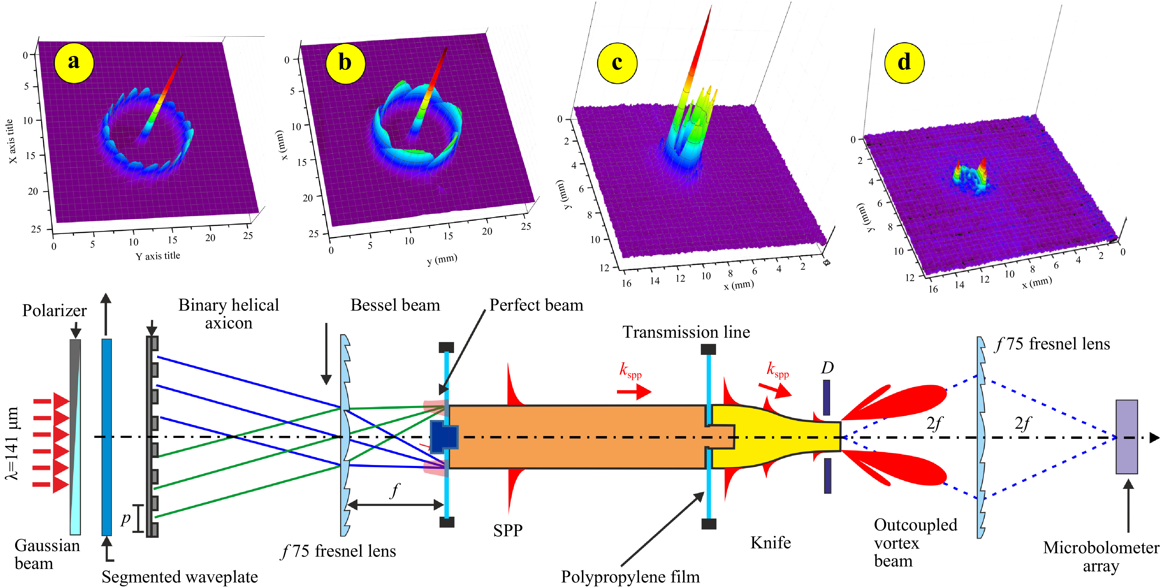
Fig. 11 Experimental setup for the generation of surface plasmon polaritons with orbital angular momentum101. The front end of the transmission line was illuminated by one of the perfect beams with topological charge
$ \left| \ell \right| = 3 $ or$ 9 $ . Their intensity distributions recorded by a Pyrocam IV are shown in insets a and b. Surface plasmon polaritons where excited by the end-fire coupling technique and propagated along a brass line covered with a 1 mm thick ZnSe layer. At the rear end of the line, plasmons transformed into vortex-free space waves and were recored with a microbolometer array. c, d Images of the outcoupled waves in-plane of the cylinder rear end, taken for radial c and azimutal d polarization of the input perfect beam with$ \left| \ell \right| = 3 $ .The plasmons excited propagated, rotating, along the cylindrical line and at the exit again turned into a free-space wave. The fact of the generation of plasmons and their rotation during propagation along the cylinder has been reliably confirmed by investigation of the free-space wave outcoupled of the rear end of the cylinder. The output wave was observed when the wave illuminating the front end had radial polarization (Fig. 11c), and its intensity dramatically decreased in a case of azimuthal polarization (Fig. 11d). Residual radiation is observed due to a small fraction of radially polarized radiation generated by the segment plate. Since plasmons can only exist as TE waves, the observed effect unambiguously confirms their existence.
The experiments showed as well that in a sequence of investigating transformations “vortex wave → rotating plasmon → outcoupled free-space wave”, the transverse component of the Poynting vector is conserved for all carriers in this chain. Since, as mentioned above, perfect beams have the same diameters, simultaneous generation of plasmons with different orbital angular momenta is possible. It can be expected that the wave emitted due to plasmon diffraction at the rear end of the line will retain the combination of topological charges and the information can then be demultiplexed. Demultiplexing the signal will also require the use of diffractive elements, such as a Dammann grating104, or elements for correlation analysis105.
-
Summarizing the results, let us list the possibilities offered by the use of a powerful monochromatic frequency-tunable terahertz radiation source for holographic research.
1. We have demonstrated the efficiency of digital and computer holography methods in the terahertz range, using the Novosibirsk free electron laser as a radiation source. The techniques for recording holograms we created or adapted to the terahertz range made it possible to record digital holograms and reproduce images, in certain cases with a resolution close to the wave limit. The high power of NovoFEL and the possibility of recording terahertz images with an MBA with a frequency of up to 20 fps enable recording series of holograms of dynamic processes. Diffractive optical elements synthesized on the computer and made of high-resistance silicon or artificial diamond make it possible to form 2D and 3D light fields with specified intensity or amplitude-phase distributions and with a specified polarization state, which is often necessary in development of optical systems in the terahertz range.
2. For the calculation and modeling of diffractive optical elements (computer-generated holograms) of the terahertz range, methods for solving direct and inverse problems of the theory of diffraction, previously developed and studied in the optical wavelength range, were successfully used. At the same time, for the manufacture of calculated diffractive optical elements, new technologies were developed for the formation of a phase diffractive microrelief on substrates of terahertz optical material with high radiation resistance.
3. A free electron laser in the terahertz range with a wavelength tunable in a wide range makes it possible to use the fabricated diffractive optical elements with a continuous profile for experiments in various regions of the terahertz range with a wavelength step corresponding to a change of
$ (2m) \pi $ ($ m=0,1.2... $ ) in the phase shift on the element microrelief. Binary elements, in addition, are able to work correctly when the radiation wavelength is detuned from the calculated one by 10 - 15%.4. Due to the large (relative to the optical range) wavelength, a terahertz laser with a tunable wavelength and high radiation power, such as NovoFEL, allows full-scale simulation of the interaction of coherent radiation with substantially subwavelength 2D and 3D structures. This approach is free from the disadvantages of computer modeling105. Note that analogs of some experiments, the results of which are presented in this article, are practically impossible in the optical range.
-
The studies described in “Imaging devices”, “Vortex microbeam arrays with a given topological charge in the Talbot configuration”, “Vector vortex beams”, “Generation of vortex surface plasmon polaritons using perfect beams” sections were supported by the Russian Science Foundation grant No. 19-12-00103, “Classical holography imaging” section by RFBR No. 18-32-00407 and “Diffractive optical elements”, “Material and technologies for DOE manufacturing”, “Binary and multilevel DOEs for focusing into given 2D and 3D areas”, “DOE for mode content control” and “Multichannel free space communication and lidar” sections by RSF No. 19-72-20202. The authors are grateful to V. I. Konov, G. N. Kulipanov, V. A. Soifer, and N. A. Vinokurov for their support of the research underlying this review, as well as V. S.Cherkassky, V. V. Gerasimov, O. E. Kameshkov, M. S. Komlenok, T. V. Kononenko, M. S. Mitkov, N. D. Osintseva, A. K. Nikitin, K. N. Tukmakov, A. S. Reshetnikov, coauthors of our articles on holography and diffractive optics. We also thank the NovoFEL team, Ya. V. Getmanov, Ya. I. Gorbachev, M. A. Scheglov, D. A. Skorokhod, and O. A. Shevchenko for technical support. The experiments were carried out at the Novosibirsk Free Electron Laser Facility, which is part of “the Siberian Synchrotron and Terahertz Radiation Center”. This manuscript has been prepared with the help of I. G. Sokolova and N. Dessmann.
Holography with high-power CW coherent terahertz source: optical components, imaging, and applications
- Light: Advanced Manufacturing 3, Article number: (2022)
- Received: 09 September 2021
- Revised: 25 April 2022
- Accepted: 25 April 2022 Published online: 09 June 2022
doi: https://doi.org/10.37188/lam.2022.031
Abstract: This paper presents the results of 15 years of studies in the field of terahertz holography at the Novosibirsk free electron laser. They cover two areas: research on obtaining holographic images in the terahertz range and the use of diffractive optical elements to form high-power terahertz radiation fields with specified characteristics (intensity, phase, and polarization), using well-studied and widely applied in the optical range methods of optical (analog), digital, and computer-generated holography. All experiments were performed with the application of high-power coherent monochromatic frequency-tunable radiation from the Novosibirsk free electron laser. The features of hologram registration in the terahertz range are described. Methods, technologies, and optical materials for terahertz holographic elements are discussed. A wide range of promising applications of high-power terahertz fields with a given spatial structure is considered. The results of the study of terahertz holograms recorded as digital holograms, as well as radiation-resistive optical elements realized as computer-synthesized holograms, are presented.
Research Summary
Holography expanded to submillimeter range
Holography has become part of our daily life. ID cards, CDs, medical imaging, and augmented reality are examples of the widespread use of holographic imaging. The first holograms were recorded as interference patterns on photo plates illuminated by direct laser radiation and light scattered from objects. Now, computers can instantly calculate holograms of any given objects (even nonexistent ones) and transmit them in real time to spatial light modulators, illumination of which enables formation of the required image. However, previously developed methods are inapplicable in the case of submillimeter (terahertz) radiation. Yulia Choporova and her colleagues from Novosibirsk and Samara Universities and BINP SB RAS report on the development of analog, digital, and computer holography using terahertz radiation from the Novosibirsk free electron laser and give examples of its application in photonics, plasmonics, and telecommunications.


Rights and permissions
Open Access This article is licensed under a Creative Commons Attribution 4.0 International License, which permits use, sharing, adaptation, distribution and reproduction in any medium or format, as long as you give appropriate credit to the original author(s) and the source, provide a link to the Creative Commons license, and indicate if changes were made. The images or other third party material in this article are included in the article′s Creative Commons license, unless indicated otherwise in a credit line to the material. If material is not included in the article′s Creative Commons license and your intended use is not permitted by statutory regulation or exceeds the permitted use, you will need to obtain permission directly from the copyright holder. To view a copy of this license, visit http://creativecommons.org/licenses/by/4.0/.

 DownLoad: