


-
With the continuous advancements in optical systems, high-performance systems in fields such as high-power laser systems1,2, advanced optics, next-generation core components, and lithography systems3,4 have placed stringent demands on the full spatial frequency errors of their optical components5,6. Typically, computer-controlled sub-aperture polishing technology is essential for achieving high-precision surfaces7. This technique uses small polishing tools to correct large surface-shape errors along a defined polishing path. The scanning strategy generally employs a raster-scanning approach8, in which the dwell time of the polishing tool influence function (TIF) is adjusted at different points along the path. The “high points” remove more material, whereas the “low points” remove less9,10. However, while this method efficiently corrects low-frequency surface shape errors, the fixed row spacing of the TIF’s feed motion, perpendicular to the scanning direction, introduces regular convolution residual errors11. These errors, known as mid-spatial frequency (MSF) ripple errors, typically occur with spatial periods ranging from 0.03 to 8 mm−1 12. For example, in inertial confinement fusion systems such as the “Shenguang” series of laser devices and the National Ignition Facility (NIF) at Lawrence Livermore National Laboratory (LLNL) in the U.S., MSF errors on the optical element surfaces can cause increased beam modulation, small-angle scattering, reduced image contrast, and even nonlinear self-focusing, which can damage optical elements and severely impair system performance13. Furthermore, the NIF imposes strict MSF error control standards, requiring each frequency band to remain below a specified threshold. Consequently, MSF errors have become the primary challenge limiting the further development of sub-aperture polishing technology.
Magnetorheological finishing (MRF) offers key advantages, including high deterministic figuring capability, ultra-high surface quality, and non-destructive subsurface processing, ensuring both component accuracy and high efficiency14,15. Compared with other traditional sub-aperture polishing techniques, such as small-tool polishing (STP) and ion beam finishing (IBF), the flexible polishing ribbon in MRF enables “flexible” contact with workpieces of various shapes. This solves the problem of poor surface adaptability caused by the rigid contact between the polishing disc and workpiece16. Additionally, unlike IBF, which has low efficiency, limited material applicability, and higher costs, MRF can process a wide range of materials with greater efficiency, making it the primary method for high-precision figuring and rapid damage removal in inertial confinement fusion systems17. Thus, an effective MSF error suppression strategy is essential to significantly enhancing the production efficiency and accuracy of MRF while expanding its application in high-end technologies.
To address this challenge, researchers have conducted extensive investigations. Existing technologies for controlling magnetorheological polishing process errors, specifically in MSF, can be categorized into three methods:
(1) Optimization of Magnetorheological Polishing Parameters and Combined Process Post-Processing Technology: The parameters of the magnetorheological polishing process are varied to minimize the MSF errors that occur. Through the integration of the characteristics of various polishing tools, iterative processes are interspersed within magnetorheological polishing, enabling each tool to leverage its spectral correction to effectively manage the residual MSF errors generated post-polishing. Shi et al. proposed a high-precision, low-defect shape-control manufacturing technique for fused silica components, merging the high-precision, low-defect processes of STP, MRF, and IBF. This combined approach harnesses the advantages of diverse polishing tools to optimize surface shape accuracy, eliminate surface defects, and mitigate MSF errors17.
(2) Modification of Polishing Paths During Machining: The introduction of MSF errors in sub-aperture polishing through regular polishing paths is considered inevitable, with MSF ripple errors significantly degrading the quality of the MSF band of a surface. The generation of MSF ripple errors can be effectively reduced by altering the regular polishing path to create heterogeneity during the polishing process. Over the past decade, researchers have investigated the underlying mechanisms and developed various algorithms for generating pseudo-random paths, including directional pseudo-random paths18, Hilbert paths19, and random maze paths20. Nevertheless, Wan et al. suggested that the pseudorandom path mechanism merely shifts the MSF error to a lower-frequency surface shape error21, resulting in a lack of further development of the pseudorandom paths. Despite this, researchers remain convinced that the feed step size in regular polishing paths is the primary factor influencing MSF ripple errors. In this context, Hu et al. proposed a step-size adaptive Archimedean path that reduces MSF errors by adjusting the path step size according to the amount of material removed22.
(3) Regulation of the Spatial Morphology and Stability of Magnetorheological TIF: The TIF of magnetorheological polishing differs from that of most sub-aperture polishing techniques. This TIF is complex and exhibits non-rotational symmetry, making it challenging to express through simple mathematical formulas. Consequently, the spatial distribution of TIF is easily controllable. When the spatial distribution of the TIF is altered, its spectral control capabilities along the line-feed direction change correspondingly, enabling the regulation of the spatial morphology of the TIF to manage MSF ripple errors. Building on this principle, Wan et al. proposed a novel machining approach for magnetorheological polishing. They adjusted the TIF to a “magic angle” and implemented a “magic step” during the machining process. At this magic step, the spatial frequency of the TIF spectrum in the direction of the magic angle is minimized, resulting in a stable surface devoid of significant MSF ripple errors without compromising the convergence of other frequency errors23. Wang et al. first identified that the fluctuation characteristics of a magnetorheological polishing ribbon induce an unsteady TIF effect. They discovered that the fluctuations in the TIF correspond to a specific optimal single-material removal thickness, enabling the introduced convolution error to be masked by the unsteady effect of the original TIF. The effectiveness of this optimal material-removal thickness in suppressing MSF ripples was verified experimentally24.
However, the material-removal mechanism of the aforementioned method still relies on the convolution of the TIF and the polishing path, resulting in the introduction of an MSF ripple error, known as convolution residuals. For this type of error to be eliminated, subsequent polishing processes that iteratively improve mid-frequency errors should be incorporated, which can be time-consuming. Furthermore, irregular polishing paths require abrupt starts and stops from the machine tool, demanding extremely high dynamic performance and often resulting in a deterioration in surface shape accuracy after processing. Thus, a simpler method is required to eliminate the MSF ripple error from the underlying mechanism and efficiently manage the complete MSF error.
In this paper, we propose a novel time-varying spacing-controllable spiral magnetorheological finishing (CSMRF) method and a time-varying TIF dwell-time algorithm designed to suppress the MSF ripple error and control the overall MSF error. First, we mathematically analyze the mechanism of the time-varying line-feed spacing and the spiral swing of the TIF concerning the MSF ripple error. Second, we introduce a nonnegative gradient-constrained dwell-time solving algorithm based on the Lagrangian regularization method, which combines the requirements of dwell-time distribution with the characteristics of CSMRF. The effects of time-varying line-feed spacing and the spiral swing of the TIF on the MSF error were analyzed through simulation, with the optimized dwell time determined via a multi-objective control genetic algorithm. The time-varying line-feed spacing and spiral angle were observed to have complementary effects. Finally, the feasibility of the proposed theory, model, and algorithm was validated through a CSMRF experiment. Through the optimization and control of these parameters, the PSD curve of the MSF band remained within the standard limits specified by the NIF, enabling fast and efficient control of the MSF error in a single magnetorheological polishing process. This research method provides new theoretical and technical support for the magnetorheological polishing process and the manufacturing of high-precision optical components. Additionally, the established model and algorithm are both general and practical, enabling further application in other sub-aperture polishing techniques that hold promise for achieving a time-varying convolution kernel (TIF), such as rotating water jet polishing25 and focusing electric lens IBF26,27.
-
In computer-controlled sub-aperture polishing technology, the TIF is defined as the distribution of material removal resulting from the polishing tool dwelling on the surface of the workpiece over a unit of time. This principle applies to various polishing methods, including ion-beam, rotating water-jet, and magnetorheological polishing, as shown in Fig. 1. Although the material-removal mechanisms of these processes differ from that of traditional polishing, they fundamentally aim to correct low-frequency surface shape errors on larger surfaces by quantifying the TIF or using mathematical modelling of the small polishing tool along a specific polishing path. Typically, the scanning strategy employs grating scanning and spiral scanning processing paths. As the dwell time of the TIF at different points along the path is varied—resulting in the convolution of the TIF and machining path—more material is removed at the “high points” and less at the “low points,” thereby achieving deterministic polishing.
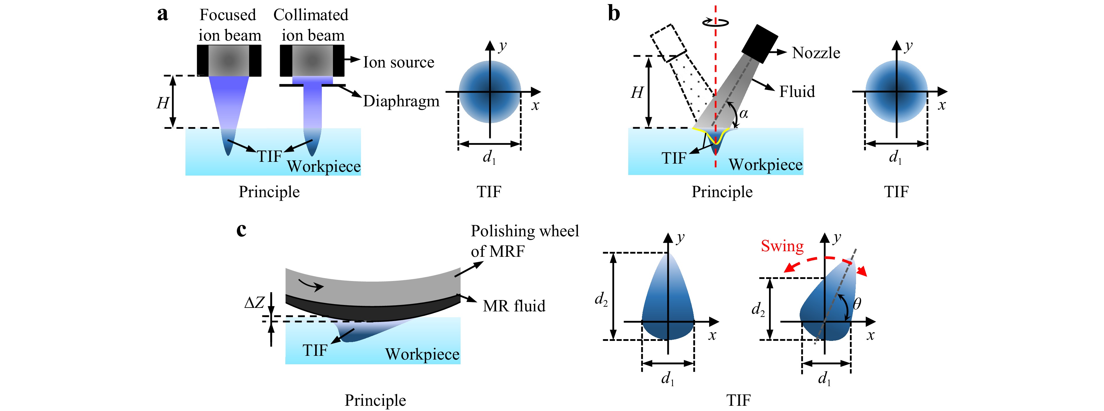
Fig. 1 Sub-aperture polishing surface material-removal distribution. a ion beam finishing b rotating water jet polishing c controllable spiral magnetorheological finishing (CSMRF).
The material removal in sub-aperture polishing can be described as the convolution of the TIF and dwell time along the path, as shown in Eq. 1 (for a grating scanning path)23. Based on this principle, a convolution residual error, referred to as the MSF ripple error, is formed on the surface of the processed component and is strongly related to the polishing path.
$$ R(x,y) = TIF(x,y) * L(x,y) $$ (1) where $ R(x,y) $ is the amount of material removed from the surface of the optical element; $ TIF(x,y) $ is the TIF per unit time; $ L(x,y) $ is the path function combined with the dwell time.
Generally, the TIF for sub-aperture polishing is designed as a Gaussian distribution. This design is associated with enhanced figuring capabilities, as observed in techniques such as ion beam and rotating water jet polishing (Fig. 1a, b). However, in magnetorheological polishing, the unique fluid dynamic pressure combined with the shear polishing method creates a D-shaped TIF structure rather than a rotationally symmetric one (Fig. 1c). Consequently, the spatial morphology of the TIF on a polished surface can be easily modified through a spiral operation, which is challenging to achieve with ion beam or water jet polishing. When the spatial morphology of the TIF on the polishing surface changes continuously, the convolution kernel (TIF) in Eq. 1 becomes time-varying, and the removal method no longer adheres to the convolution principle. Therefore, the introduction of the MSF ripple error can be suppressed by employing this principle, as demonstrated in Eq. 2.
$$ R(x,y) = \sum\limits_{i = 1}^n {\sum\limits_{j = 1}^m {TIF(x,y,{t_{ij}}) \times T(x,y)} } \ne TIF(x,y) * L(x,y) $$ (2) where $ TIF(x,y,{t_{ij}}) $ is the angle time-varying spiral TIF, and $ T(x,y) $ is the dwell time of the polishing tool at each dwelling point on the trajectory.
The conventional grating-scanning path used in the original magnetorheological polishing process is shown in Fig. 2a. $ TIF(x,y) $ is superimposed in the scanning direction and generates a one-dimensional profile cut through the red dashed line section, denoted as $ f(x) $. Consequently, the contour patterns on the surface of the polished component captured by the yellow dashed line section can be represented as $ g(x) $.
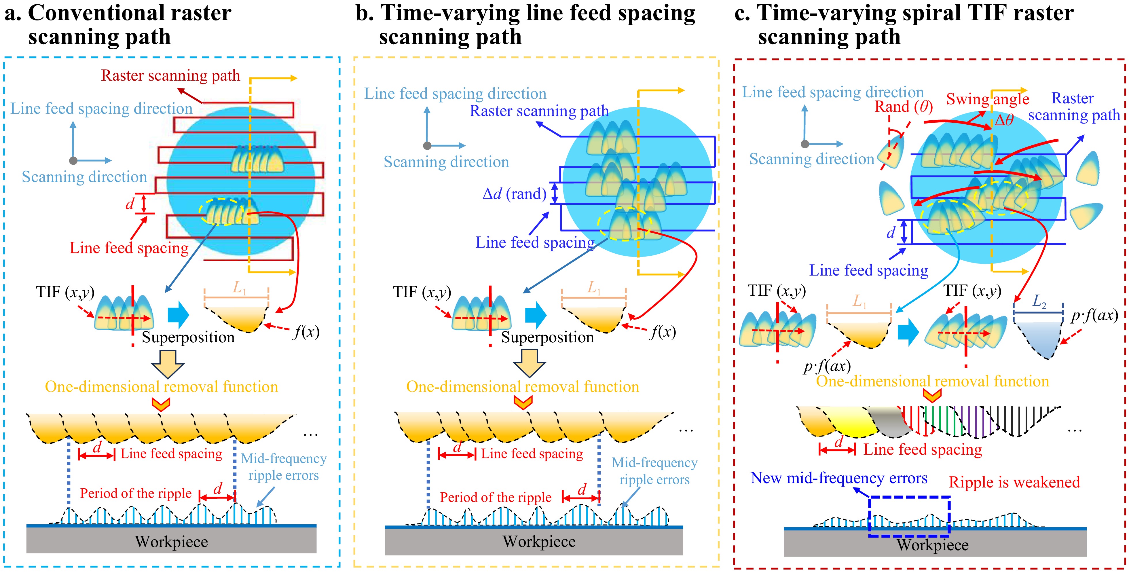
Fig. 2 Schematic of surface MSF ripple error generation under different processing strategies. a traditional raster scanning b time-varying line-feed spacing raster scanning c time-varying spiral TIF scanning.
$$ g(x) = \sum\limits_{n = - \infty }^\infty {f(x - n \cdot d)} $$ (3) where $ n $ denotes the number of superimposed one-dimensional profiles (number of lines), and $ d $ represents the grating scanning spacing.
The Fourier transform of $ f(x - n \cdot d) $ in $ g(x) $ is analyzed, and Eq. 4 is obtained according to its spectral characteristics. By replacing the independent variables in the Eq. 4 with $ u = x - n \cdot d $, we obtain Eq. 5.
$$ {G_n}(f) = \int_{ - \infty }^\infty {f(x - n \cdot d)} \cdot {e^{ - 2\pi ifx}}dx $$ (4) $$ {G_n}(f) = \int_{ - \infty }^\infty {f(u)} \cdot {e^{ - 2\pi if(u + n \cdot d)}}dx = {e^{ - 2\pi ifnd}}\int_{ - \infty }^\infty {f(u)} \cdot {e^{ - 2\pi ifu}}du $$ (5) where $ {G_n}(f) $ represents the one-dimensional profile $ f(x) $ in the frequency spectrum, and $ f(u) $ denotes the one-dimensional profile after variable substitution.
Therefore, the spectrum of the surface after polishing using the conventional grating path is
$$ G(f) = \sum\limits_{n = - \infty }^\infty {{G_n}(f)} = \sum\limits_{n = - \infty }^\infty {F(f)} {e^{ - 2\pi ifnd}} $$ (6) By substituting the Euler formula $ {e^{ix}} = \cos (x) + i \cdot \sin (x) $ into the frequency spectrum expression, we obtain Eq. 7.
$$ G(f) = \sum\limits_{n = - \infty }^\infty {F(f)} \cdot (\cos (2{\text π} fnd) - i\sin (2{\text π} fnd)) $$ (7) From the above analysis, regardless of the value of $ n $, when $ f = 1/d $, the real part of the spectrum reaches the maximum value of 1, and the phase is 0. Therefore, a peak occurs at $ f = 1/d $, and its frequency multiplies under the conventional grating scanning path. As $ n $ increases, the peak values are superimposed and finally form a large peak (periodic MSF ripple), as shown in Fig. 2a.
From Eq. 7 , we observe that the MSF ripple error can be suppressed by changing the fixed line-feed spacing $ d $ or the one-dimensional profile $ f(x) $ of the $ TIF(x,y) $. Therefore, we propose to vary the original grating scanning fixed line-feed spacing within a certain range to change $ d $ and simply spiral TIF to change $ f(x) $, thereby suppressing the MSF ripple error.
The magnetorheological polishing method using a time-varying line-feed spacing strategy is shown in Fig. 2b. $ TIF(x,y) $ is superimposed in the scanning direction, and the one-dimensional contour intercepted by the red dotted line section is $ f(x) $. No difference is observed from traditional grating scanning. After polishing, the contour line $ g(x) $ of the component surface cut off by the yellow dotted line section changes because of the change in the line-feed spacing, as shown in Eq. 8.
$$ g(x) = \sum\limits_{m = - \infty }^\infty {f(x - {d_m})} $$ (8) where $ m $ is the number of one-dimensional contour superpositions (number of lines), and $ {d_m} $ is the grating scanning spacing.
The Fourier variation in $ g(x) $ is transformed into a spectral form, as shown in Eq. 9, and the spectrum of the surface line in the direction of the polished line feed changes after polishing is obtained using the Euler formula.
$$ G(f) = \sum\limits_{m = - \infty }^\infty {{G_n}(f)} = \sum\limits_{m = - \infty }^\infty {F(f)} {e^{ - 2{\text π} if{d_m}}} $$ (9) $$ G(f) = \sum\limits_{m = - \infty }^\infty {F(f)} \cdot (\cos (2{\text π} f{d_m}) - i\sin (2{\text π} f{d_m})) $$ (10) Based on the analysis of the above Eq, during $ f = 1/{d_m} $, the real part of the frequency spectrum reaches its maximum value of 1, with a phase of 0. However, the value of $ {d_m} $ is variable and does not increase as $ m $ increases. Consequently, under the time-varying line-feed spacing grating scanning path, no periodic peaks are generated, effectively suppressing the MSF ripple error. Nevertheless, this approach results in the formation of irregular small peaks within the MSF band, manifesting as erratic “spikes” on the spectrum.
Scanning with a controllable spiral magnetorheological TIF, as shown in Fig. 2c, shows that the one-dimensional profile cut by the red dashed line through the superposition of $ TIF(x,y) $ in the scanning direction is $ f(x) $. Compared with fixed TIF scanning, $ f(x) $ changes after the spiral of the TIF at different dwell positions; the one-dimensional shape along the line-feed direction expands or contracts, with both its width and peak removal efficiency undergoing changes. In this scenario, the one-dimensional shape of the TIF, relative to the fixed strategy, becomes an $ p \cdot f(ax) $, where $ a $ is the length change factor, and $ p $ is the efficiency change factor. Therefore, the contour line $ g(x) $ of the component surface cut off by the yellow dotted line section after polishing is shown in Eq. 11.
$$ g(x) = p \cdot \sum\limits_{m = - \infty }^\infty {f(ax - md)} $$ (11) where $ m $ represents the number of superimposed one-dimensional profiles, and $ d $ is the grating scanning spacing.
The Fourier transform of $ p \cdot f(ax) $ is converted into the spectral form, as shown in Eq. 12.
$$ {G_n}(f) = \frac{{{p_m}}}{{{a_m}}}F(f({a_m}x)) $$ (12) Eq. 12 is substituted into Eq. 11 and summed to obtain the surface contour spectrum in the direction of the polished line feed.
$$ G(f) = \sum\limits_{m = - \infty }^\infty {\frac{{{p_m}}}{{{a_m}}} \cdot F(f({a_m}x))} \cdot (\cos (2{\text π} fmd) - i\sin (2{\text π} fmd)) $$ (13) where $ G(f) $ is the spectrum of the surface texture in the direction of the line feed after the spiral magnetorheological finishing, $ i $ is the imaginary symbol, $ m $ is the line-feed number of the grating scanning, $ {p_m} $ is the efficiency change factor when the number of line feed is $ m $, and $ {a_m} $ is the length change factor when the number of line feeds is $ m $.
From the above analysis, when $ f = 1/d $, the real part of the spectrum reaches the maximum $ {p_m}/{a_m} $, and the phase is zero. However, the value of $ {a_m} $ changes over time, which causes the spectrum of $ F(f(ax)) $ to be stretched during the process of summing, along with the $ m $ superposition. The peaks are misaligned, which weakens the peaks of the periodic ripples. The maximum value of the spectrum also changes with $ {p_m} $ and $ {a_m} $, thereby weakening the ripple periodicity. In addition, because the spiral action ofthe TIF is similar to that of erase action, this method may effectively smooth the spike error generated on the surface. Therefore, we combine the time-varying line-feed spacing method, which eliminates the periodic MSF ripple error from the root, with the controllable spiral magnetorheological grating scanning method, which can weaken the ripple structure at various frequencies and smooth the “spikes.” Finally, we develop a novel MSF error-suppression strategy for a time-varying spacing-swing CSMRF method. A schematic of the CSMRF method is shown in Fig. 3.
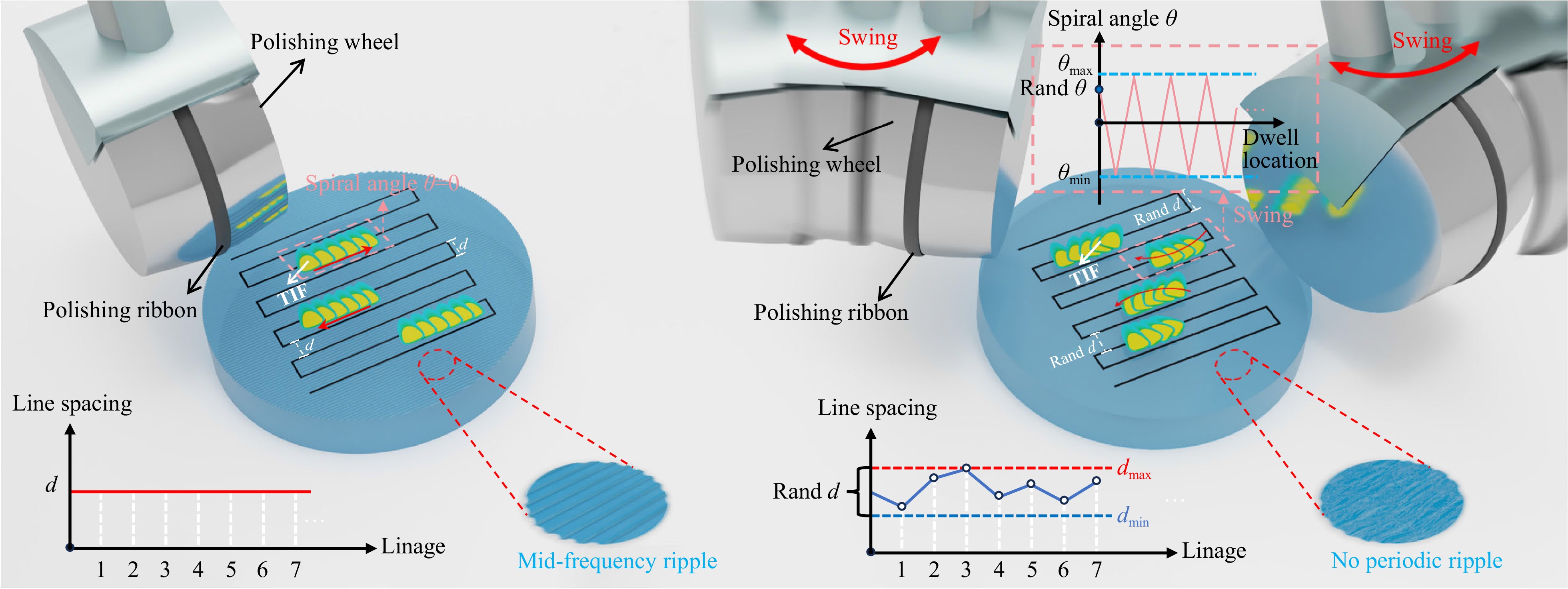
Fig. 3 Schematic of the CSMRF method (time-varying spacing-swing strategy).
-
The traditional computer-controlled optical surface (CCOS) polishing material-removal method employs a two-dimensional convolution approach, as expressed in Eq. 1. When the initial surface error and the TIF are given, the process of solving the dwell time is the process of solving the deconvolution28. Traditional dwell-time solving models include the discrete convolution and linear equations models. However, for CSMRF, the TIF exhibits non-rotational symmetry characteristics; thus, the influence of the spiral angle on the TIF should be considered. Because the TIF varies over time, the convolution kernel becomes time-varying, rendering traditional convolution removal theory inapplicable. A dwell-time solution algorithm based on the discrete convolution model is insufficient for addressing this problem. Instead, in this study, we employ a dwell-time solving algorithm rooted in the linear equations model to solve the problem of a time-varying TIF relative to the machining position. We employed the lsqlin function to solve large sparse linear matrix equation problems and obtain constrained nonnegative solutions29,30. This method ensures that the calculated dwell times exceed the minimum value achievable based on the machine tool speeds. The lsqlin function utilizes a constrained linear least-squares algorithm, with the iteration process grounded in a preconditioned conjugate gradient method. The initial point for lsqlin was set to 1, with an upper limit of 4 and a lower limit of 0.02, ensuring compliance with the speed requirements for machine tool motion. In addition, we applied a non-negative gradient constraint dwell-time solution algorithm based on the Lagrange regularization method to smooth the distribution of the solution. The specific algorithm implementation process is shown in the Supplementary Information.
According to the analysis presented in the previous section, different spiral angles of the TIF and path strategies exert varying degrees of influence on the MSF error of the surface. This differs from fixed line-feed spacing in magnetorheological polishing, where the frequency band error remains unchanged when the TIF, material-removal amount, and line-feed spacing are determined. However, in CSMRF, the MSF error can be managed by adjusting the spiral angle of the TIF and the line-feed spacing, thus significantly suppressing the MSF ripple error. Nonetheless, as noted in the previous analysis, even after the MSF ripple error is reduced, the root mean square (RMS) accuracy of the surface shape resolved by the algorithm remains constant (Supplementary Information Eq. 21), which inevitably results in the deterioration of other frequency bands. Because existing IBF methods can effectively correct low-frequency errors with a spatial period of 0.1 mm−1 or less31,32 and smoothing technology can effectively manage high-frequency errors with a spatial period exceeding 5 mm−1 33, in this paper, we focus specifically on controlling the MSF error within the range of 0.1 to 5 mm−1. By synergistically optimizing the spiral angle of the TIF and the line-feed spacing, we can control the MSF error within a specific frequency band, thereby pushing the error into a frequency range that is easier to correct.
Therefore, drawing on the principles of genetic algorithms34 and the characteristics of time-varying spacing and swing CSMRF, we considered the spiral angle of the TIF at the initial position of each line feed and the value of the time-varying line-feed spacing as our optimization targets. We then designed and constructed a fitness function for controlling the MSF band error to optimize the fitness value under various constraints of the MSF error. Through multiple iterations, we obtained a combination of the adaptive TIF angle and line spacing that minimizes the error within the specific MSF band.
To effectively control the MSF error, we designed the following fitness function: the design criterion prioritizes minimizing the error at the frequency of the MSF ripple, which is the most challenging to control in sub-aperture polishing. Additionally, to minimize the overall MSF error, we selected three frequency points within the MSF frequency band. The overall frequency band is reduced by minimizing the values of these three frequency points. Furthermore, to avoid negative values in the final solution for dwell time and to ensure that the theoretical feed rate satisfied the dynamic performance requirements of the machine tool, we utilized the lsqlin function combined with the dwell time gradient constraint to solve for dwell time. Thus, the process of solving for a specific MSF error control using a genetic algorithm is conducted as follows: First, a set of initial TIF angles and line-feed spacing combinations is generated through genetic algorithm optimization. Next, the residual error calculations are performed using Supplementary information Eq. S4, and the error values for the specific target frequency band are extracted to compute the fitness value, as shown in Eq. 14. Finally, iterative optimization is conducted repeatedly to obtain the optimal matching scheme. A flowchart of the algorithm is presented in Fig. 5.
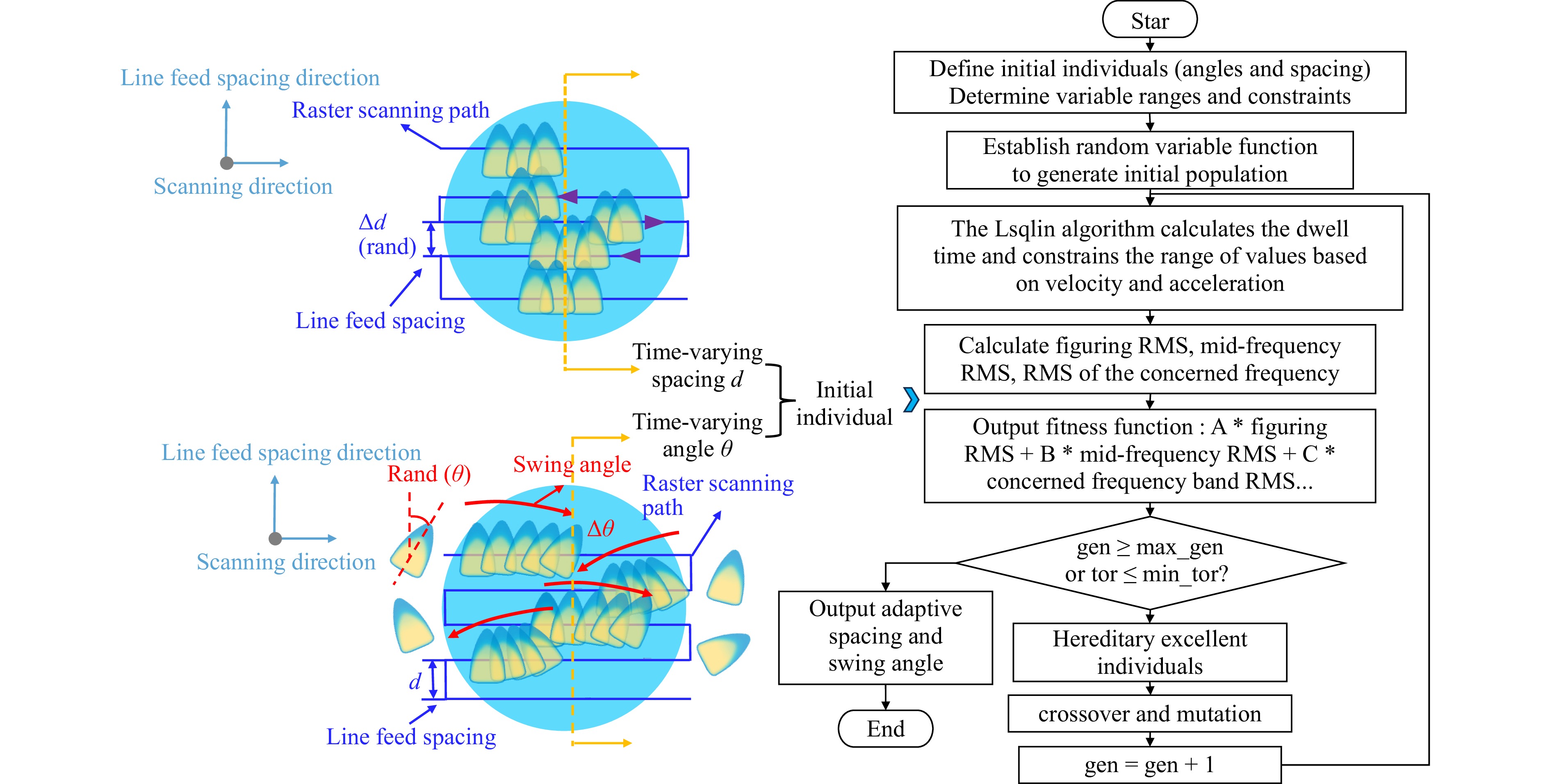
Fig. 4 Flowchart for solving the dwell time of specific MSF error control based on a genetic algorithm.
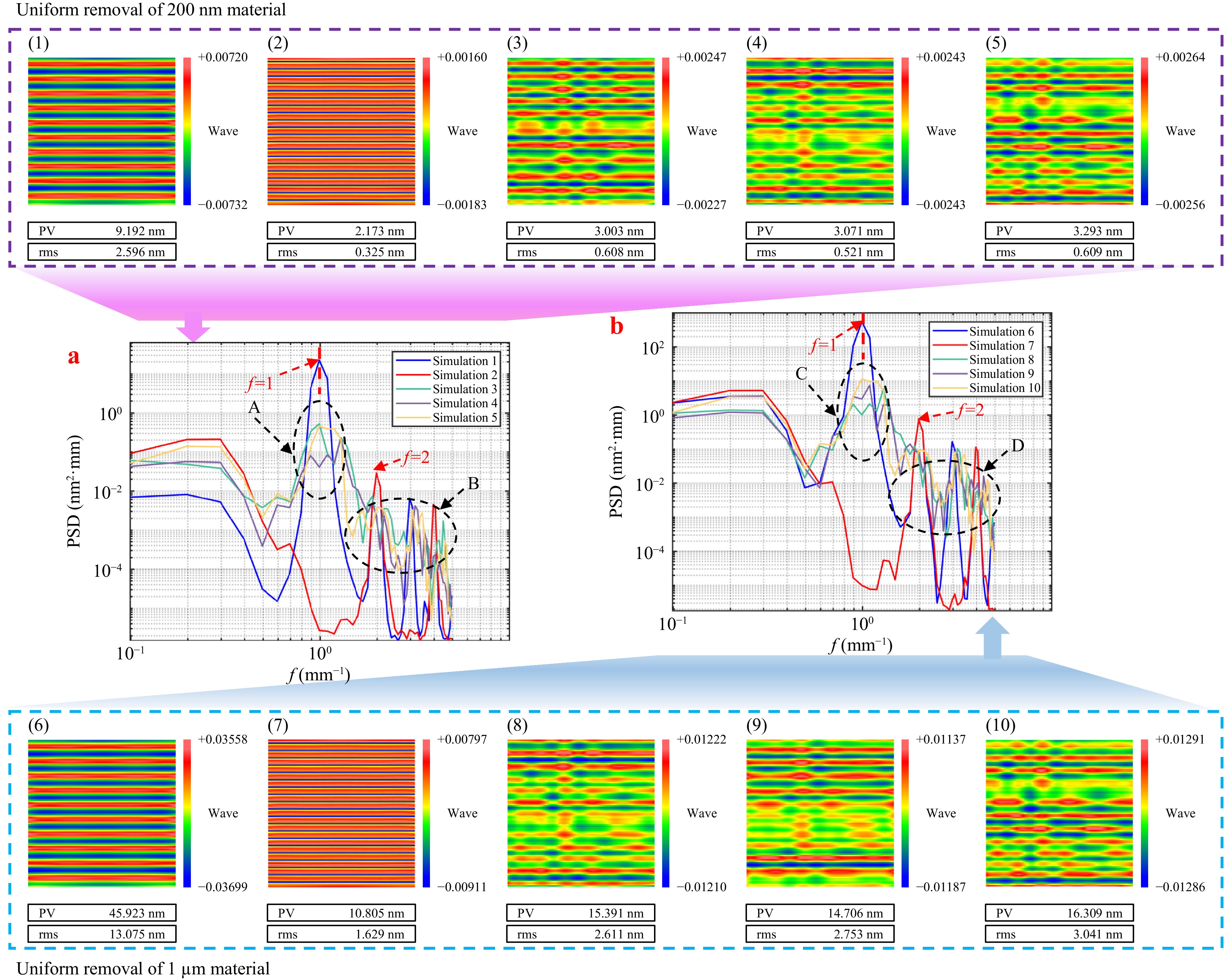
Fig. 5 MSF error and MSF PSD result of magnetorheological polishing simulation under the time-varying line-feed spacing strategy.
$$\begin{split} FIT =\;& {q_1} \cdot RM{S_l} + {q_2} \cdot PS {D_{ripple}} + {q_3} \cdot PS {D_{m1}} \\&+ {q_4} \cdot PS{D_{m2}} + {q_5} \cdot PS {D_{m3}} \cdots \end{split}$$ (14) where PSD is the power spectral density of the calculated residual surface shape error, and $ {q_1} $, $ {q_2} $, $ {q_3} $, $ {q_4} $, and $ {q_5} $ represent the weight values of the low-frequency surface RMS and MSF ripple amplitude of the PSD, first specific frequency, second specific frequency, and third specific frequency, respectively. The larger the value, the higher the requirement. In addition, to ensure uniformity of the MSF error on the polished surface, we obtained the RMS and PSD data in the fitness function using the five-point average method. Five 10 mm × 10 mm areas are randomly selected on the processing surface, and the average value is analyzed.
-
We conducted a simulation analysis of CSMRF, utilizing the experimentally obtained TIF to process an absolute plane through uniform material removal. Unlike magnetorheological polishing in fixed line-feed mode, uniform material removal in this mode does not require solving for dwell time. This is because, when the TIF remains unchanged, the time for each processing point is equal, resulting in identical values across all positions in the removal matrix. However, when the spatial morphology of the TIF varies, the uneven superposition of the TIF on the surface necessitates the application of the non-negative gradient-constrained dwell time-solving algorithm described in the previous section to achieve uniform material removal. In this context, uniform removal is equivalent to figuring, as removing two uniform material layers with different amounts is akin to correcting distinct surface shape errors. The feasibility of this theory was confirmed through simulation experiments that uniformly removed material. To assess the impact of the time-varying line-feed spacing strategy on suppressing the MSF ripple error, we performed ten sets of simulations, with the simulation parameters detailed in Table 1. Considering common machine performance limitations, feed speed, and processing efficiency, we selected a minimum line-feed spacing of 0.5 mm and a maximum of 1 mm, establishing the range for the time-varying line-feed spacing strategy between these values. By comparing the simulation results, we present the error distribution of the MSF band on the surface of the component after processing in Fig. 6, along with the corresponding PSD curve in the line-feed direction. To eliminate the interference of low-frequency errors during the analysis, we removed 36th-order Zernike polynomials from the results. The surface area analyzed for MSF error was 10 mm × 10 mm, with a grid resolution of 0.1 mm. Therefore, the MSF error that could be analyzed was between 0.1 and 5 mm−1. This frequency range is crucial in sub-aperture polishing, as it is the range in which the MSF ripple error occurs.
Experiment number Line-feed spacing
(mm)Depth of material removal (nm) Range of spiral angle (°) RMS MSF error (nm) 1 1 200 0 2.596 2 0.5 200 0 0.325 3 0.5–1 200 0 0.608 4 e 200 0 0.521 5 0.5–1 200 0 0.609 6 1 1000 0 13.075 7 0.5 1000 0 1.629 8 0.5–1 1000 0 2.611 9 0.5–1 1000 0 2.753 10 0.5–1 1000 0 3.041 Table 1. Simulation parameters and RMS MSF error results of magnetorheological polishing under the time-varying line-feed spacing strategy
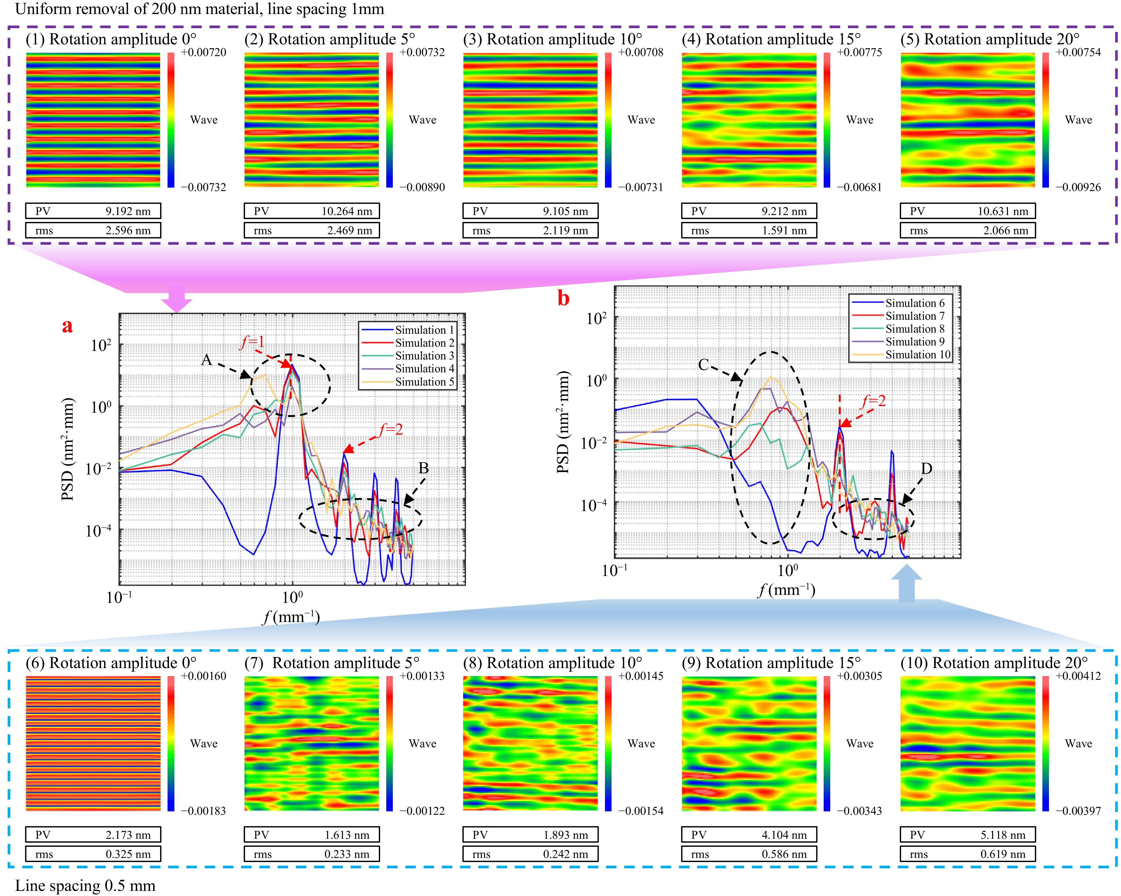
Fig. 6 MSF error and MSF PSD results from experiments 1–10 of magnetorheological polishing simulation under the time-varying spiral swing of the TIF strategy.
By contrasting the results depicted in Fig. 5(1)-(5), we can conclude that when a time-varying line-feed spacing strategy was not implemented, MSF ripple errors were present on the surface with both 1 and 0.5 mm line spacings. At a line spacing of 1 mm, the RMS MSF was significantly large, and the PSD curve exhibited prominent peaks at a spatial period of 1 mm−1 and its harmonics. In comparison, adopting a 0.5 mm line-feed spacing effectively reduced the RMS MSF error, with peaks at the spatial frequency of 2 mm−1 and its harmonics markedly lower than those observed with a 1 mm line-feed spacing. Thus, while reducing the line spacing diminished the amplitude of the MSF ripple errors, it did not completely eliminate them, which corresponded with the findings of most researchers.
When the time-varying line-feed spacing strategy was employed, the simulation results revealed no apparent periodic peaks in the PSD curves at either 1 or 2 mm−1 spatial periods, and the surface shape errors did not exhibit periodic structures. This observation was consistent with the schematic illustration of one-dimensional surface errors in Fig. 3b. In area A of Fig. 5a, the periodic MSF ripple errors generated by the original fixed line-feed spacing were significantly suppressed, whereas area B exhibited multiple irregular minor peaks, corroborating the theoretical analysis presented in Section 2 and confirming the validity of the theoretical predictions. Furthermore, the variations in the RMS MSF and PSD curves in simulations (3)-(5), which involved different line spacing values, provided evidence for the subsequent optimization of the line-feed spacing to control specific frequencies.
The comparison of the simulation results in Fig. 5(1)-(5) further indicates that as the depth of removal increased, the RMS in the MSF range increased by several times, whereas the characteristic frequencies of the PSD curve (spatial frequencies of 1 and 2 mm−1) increased by two orders of magnitude. This increase poses significant challenges for the processing requirements of optical components. Additionally, the PSD curves for the removal of 200 nm and 1 micron of material demonstrated similar trends, highlighting the universality of the time-varying line spacing method in controlling MSF ripple errors across various surface shape errors.
To validate the CSMRF method, we conducted a series of 20 simulations using the parameters outlined in Table 2. Considering the dynamic performance of the CSMRF device and the stability of the MR fluid recovery, our spiral angle range was set to ± 20°. Comparative analyses of the simulation results, including the MSF error distribution and PSD analysis of the processed component surface, are shown in Figs. 7, 8, respectively.
Experiment number Line-feed spacing
(mm)Depth of material removal (nm) Range of spiral angle (°) RMS MSF error (nm) 1 1 200 0 2.596 2 1 200 5 2.469 3 1 200 10 2.119 4 1 200 15 1.591 5 1 200 20 2.066 6 0.5 200 0 0.325 7 0.5 200 5 0.233 8 0.5 200 10 0.242 9 0.5 200 15 0.586 10 0.5 200 20 0.619 11 1 1000 0 13.075 12 1 1000 5 12.218 13 1 1000 10 9.569 14 1 1000 15 7.286 15 1 1000 20 6.917 16 0.5 1000 0 1.629 17 0.5 1000 5 1.312 18 0.5 1000 10 1.068 19 0.5 1000 15 1.182 20 0.5 1000 20 1.491 Table 2. Simulation parameters and RMS MSF error results of magnetorheological polishing under the time-varying spiral swing of the TIF strategy
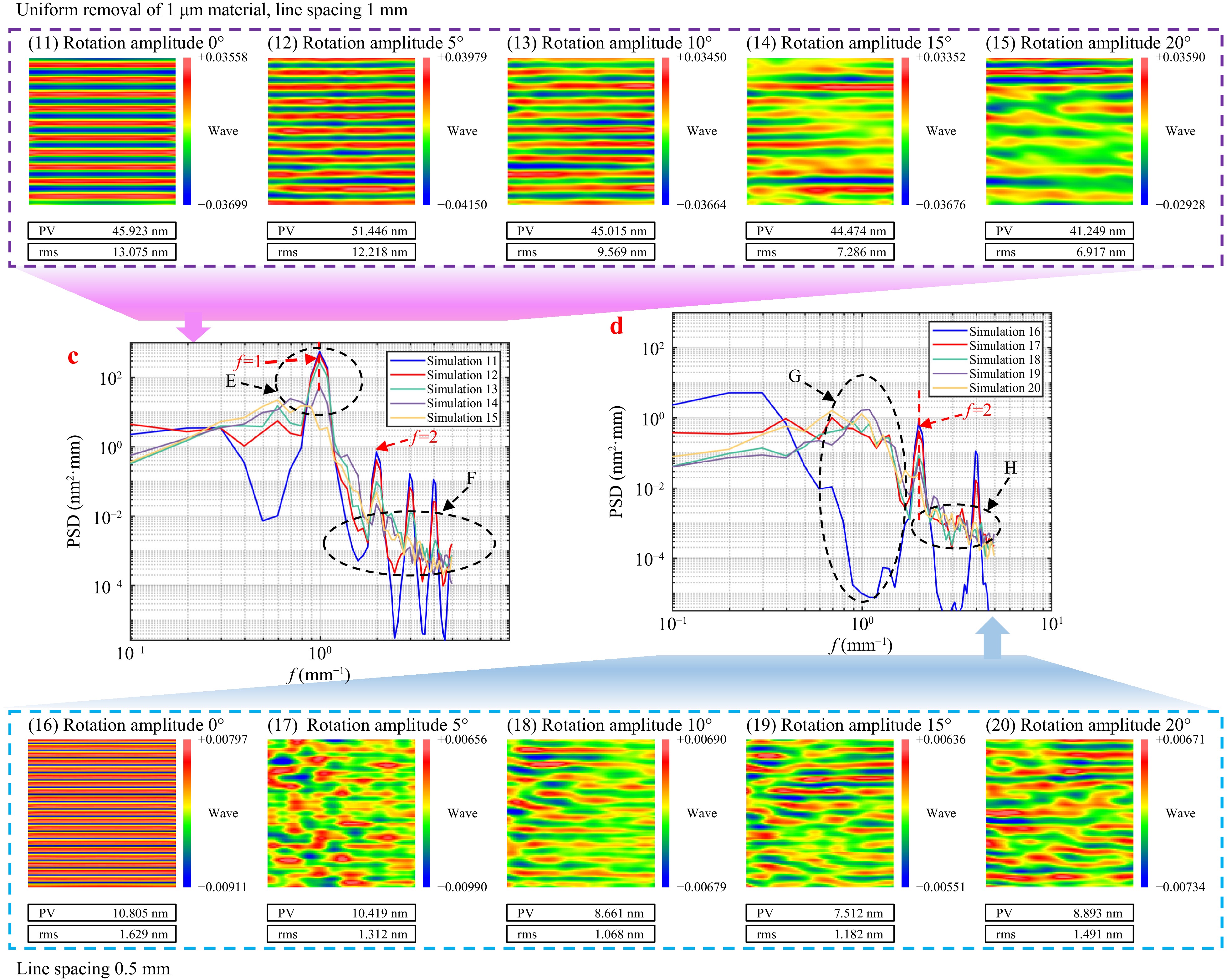
Fig. 7 MSF error and MSF PSD results from experiments 11–20 of magnetorheological polishing simulation under the time-varying spiral swing of the TIF strategy.
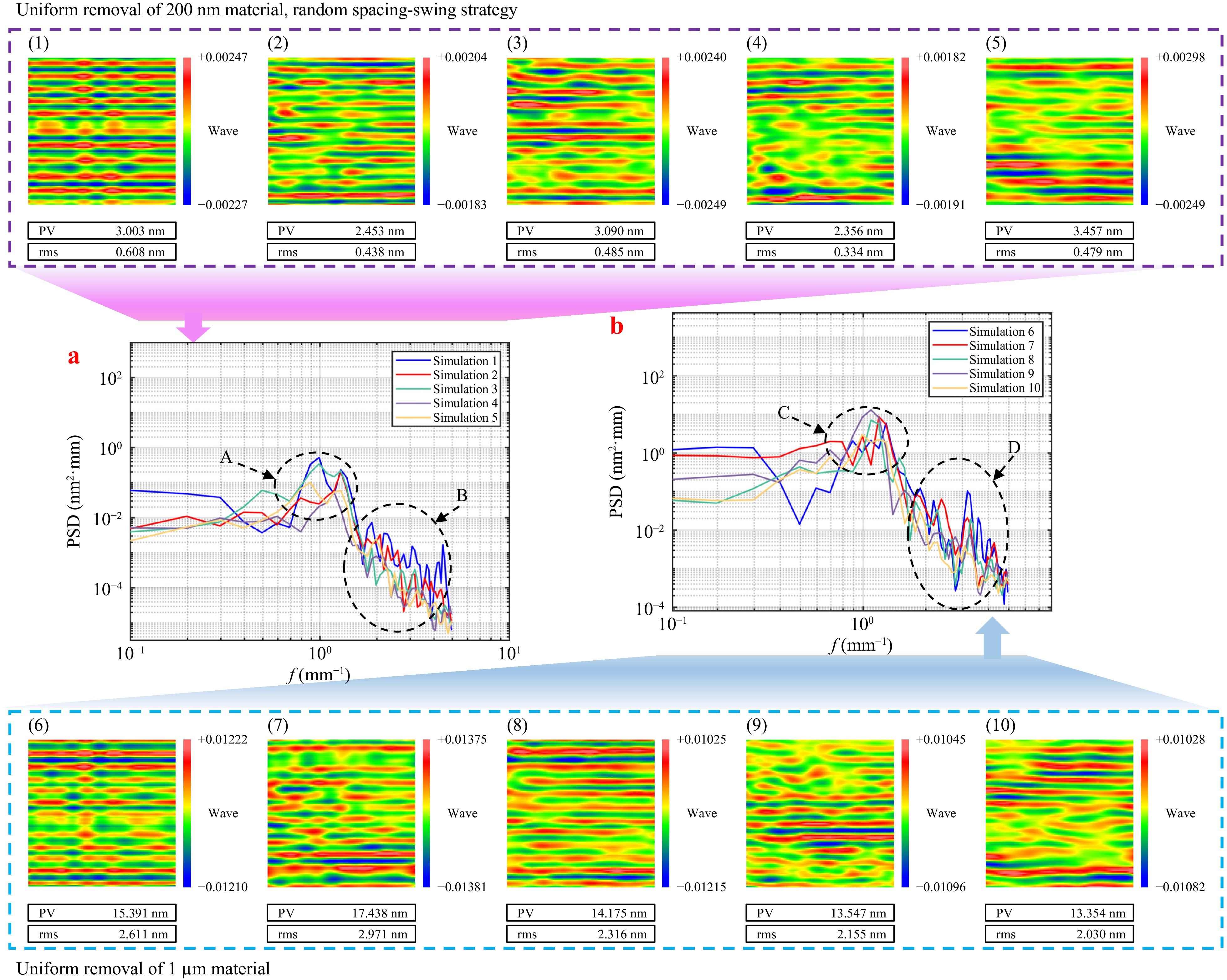
Fig. 8 MSF error and MSF PSD results of CSMRF simulation under the time-varying spacing-spiral strategy.
Comparing Fig. 6a with Figs. 1-5, we observed that the MSF surface errors under both the 1 and 0.5 mm line-feed spacing strategies were smoothed out when the time-varying spiral strategy was adopted. When the line-feed spacing was set at 1 mm, the deeper MSF ripples presented a challenge for the minor spiral angles to smooth effectively. Consequently, only when the spiral angle reached ± 15° did a noticeable smoothing of the periodic ripples occur, as depicted in Fig. 6(4). In this state, the overall RMS MSF effectively decreased. However, as the spiral angle increased further, the overall RMS MSF value began to deteriorate. As shown in area A of Fig. 6a, increasing the amplitude of the spiral angle significantly decreased the characteristic frequency peaks associated with the MSF ripples, validating the effectiveness of the rotational angle in suppressing MSF errors. In contrast, area B of Fig. 6a reveals that, unlike the time-varying line-feed spacing strategy—which generated multiple peaks at other frequencies—the PSD curves under the time-varying spiral angle strategy appeared relatively smooth across various frequencies. This finding was consistent with the theoretical analysis presented in Section 2, affirming the validity of using a time-varying spiral to suppress MSF errors.
Further analysis of Fig. 6b, when compared with Fig. 6(6)-(10), indicates that, when the line spacing was set at 0.5 mm, the intermediate frequency ripple was shallow, requiring only a small angle to homogenize the MSF ripple error. As shown in Fig. 6(7), a spiral range of merely ± 5° was sufficient to smooth out the MSF ripples and effectively suppress the RMS MSF. However, increasing the spiral angle further worsened the RMS MSF value. Although the rotation of the TIF aided in smoothing the MSF ripple error, when the MSF ripple error was sufficiently smoothed, further increases in the spiral angle introduced errors caused by the spiral process, as shown in area C of Fig. 6b. Moreover, the analysis of areas A and E in Figs. 6, 7 shows that although the time-varying spiral strategy effectively lowered the characteristic peaks of the MSF ripples, these peaks did not disappear entirely. Thus, smaller time-varying spiral angles cannot completely eliminate periodic ripples but can homogenize errors across the full spectrum, effectively controlling the RMS MSF.
The analysis of Fig. 7c, d reveals that while the suppression characteristics and trends of the MSF errors using the time-varying spiral strategy appeared similar regardless of the removal depth, the optimal oscillation angles differed for varying line spacings and removal depths. Additionally, the optimal angles for the different line = feed spacings varied. Therefore, effectively suppressing MSF errors requires a comprehensive analysis of the amount of material removed, line-feed spacing, and range of spiral angles. This involves optimizing combinations of different time-varying line-feed spacings and initial time-varying spiral angles, thereby achieving effective directional control over MSF errors. Such optimization also lays the groundwork for further refinement of the initial spiral angles and line-feed spacings to control specific frequencies.
Sections C and G in Figs. 6, 7 show that the time-varying spiral strategy exacerbated lower frequencies in the MSF range. This deterioration occurred from the changes in the shape of the TIF at each position owing to its spiral movement. In fixed line spacing simulations, this frequency area was positioned lower and was influenced by the accuracy of machine tool positioning (which is akin to a small range of time-varying line-feed spacings) and the non-stationary effects of the TIF29. The TIF changed in real time at each dwell point, which suggests that the actual machining process may not achieve the significantly low values observed in simulations. Instead, it may align more closely with the outcomes of the time-varying spiral angle strategy.
In summary, the time-varying spiral strategy effectively homogenizes errors, including MSF ripple errors, and has the potential to reduce the overall RMS MSF. However, completely eliminating MSF ripple errors may require a larger range of rotation angles, which can inadvertently result in increased MSF errors. To address this challenge, we integrated the benefits of both time-varying line-feed spacing and time-varying spiral swing TIF strategies. By optimizing the matching conditions between the time-varying selection of line spacings and spiral angles, we could effectively control the MSF errors on the surfaces of the machined components.
-
Based on the preceding analysis, the time-varying line-feed strategy effectively eliminates the peak values of MSF ripple errors while controlling the reduction of specific frequency errors. However, this approach also introduces multiple sharp frequency peaks, resulting in an overall increase in the MSF band error. In contrast, the time-varying spiral TIF strategy can significantly reduce the RMS of the entire MSF band error and smooth out higher peak values. To leverage the strengths of both methods, we propose a time-varying spacing-swing CSMF method that integrates the advantages of time-varying line-feed spacing and time-varying spiral TIF strategies. We conducted a series of ten simulations using the parameters listed in Table 3. The simulation results, including the MSF band error distribution on the surface of the processed component and the corresponding PSD curves, are presented in Fig. 8.
Experiment number Line-feed spacing
(mm)Depth of material removal (nm) Range of spiral angle (°) RMS MSF error (nm) 1 0.5–1 200 0 0.608 2 0.5–1 200 5 0.438 3 0.5–1 200 10 0.485 4 0.5–1 200 15 0.334 5 0.5–1 200 20 0.479 6 0.5–1 1000 0 2.611 7 0.5–1 1000 5 2.971 8 0.5–1 1000 10 2.316 9 0.5–1 1000 15 2.155 10 0.5–1 1000 20 2.030 Table 3. Simulation parameters and RMS MSF error results of CSMRF under the time-varying spacing-swing spiral strategy
As shown in Fig. 8, the combined application of the time-varying spiral swing strategy with the time-varying line-feed spacing strategy effectively reduced the RMS of the MSF errors on the surface. However, this improvement had its limitations. The optimal conditions were observed at a spiral amplitude of 15° for a material-removal depth of 200 nm. In contrast, when the removal depth increased to 1 micron, the ideal spiral amplitude increased to 20°. This correlation corresponded with the depth of the residual ripples induced by the time-varying line-feed spacing; deeper grooves necessitate a larger rotation angle for effective smoothing.
Fig. 8a, b show that regions A and C had a notable shift in the spatial frequency values corresponding to the peaks as the spiral amplitudes vary, demonstrating a trend toward moderation with the introduction of oscillatory angles. Additionally, regions B and D indicate that the multiple characteristic peaks introduced by the time-varying line-feed spacing strategy were smoothed out when integrated with the time-varying spiral strategy, resulting in a more uniform PSD curve and effectively controlling the overall RMS of the MSF segment.
Upon comprehensive analysis, we observed that the proposed CSMRF method, which combines both time-varying line-feed spacing and time-varying spiral strategies, successfully mitigates errors associated with MSF ripples while enhancing the total MSF error. This is corroborated by Figs. 5(3)-(5), (8)-(10), 9, which consistently indicate variations in the RMS MSF and PSD peaks corresponding to spatial frequencies when different time-varying values for line spacing were employed. Moreover, changes in the initial orientation of the time-varying spiral angles also influenced the RMS MSF. Therefore, optimizing the combinations of the initial spiral angle and line-feed spacing by TIF is crucial for collaboratively refining control over specific MSF errors, as shown in Fig. 4.
In conjunction with the specific MSF error control dwell time solution model based on the genetic algorithm proposed in the second section, we conducted eight sets of simulations. We observed that the RMS MSF was minimized at a spiral angle of 15° when 200 nm of material was removed, whereas a spiral angle of 20° yielded the minimum RMS for a 1 µm material removal. The simulation parameters are detailed in Table 4. By comparing the simulation results, we present the error distribution of the MSF band on the component surface, the PSD curve for line-feed direction analysis, and the fitness evolution diagram post-processing in Fig. 9.
Experiment
numberLine-feed
spacing (mm)Depth of material
removal (nm)Range of spiral
angle (°)Fitness function RMS MSF error
(nm)1 0.5 200 0 NaN 0.325 2 0.5–1 200 15 NaN 0.334 3 0.5–1 200 15 150·RMSl + 9·PSD2 + 2·PSD1 + 0.1·PSD0.6 0.317 4 0.5–1 200 15 150·RMSl + 9·PSD2 + 10·PSD1 + 0.1·PSD0.6 0.328 5 0.5 1000 0 NaN 1.629 6 0.5–1 1000 20 NaN 2.030 7 0.5–1 1000 20 10·RMSl + 400·PSD2 + 0.5·PSD1 + PSD0.6 1.607 8 0.5–1 1000 20 10·RMSl + 400·PSD2 + PSD1 + PSD0.6 1.568 Table 4. Simulation parameters and RMS MSF error results of the specific MSF error control model based on the genetic algorithm
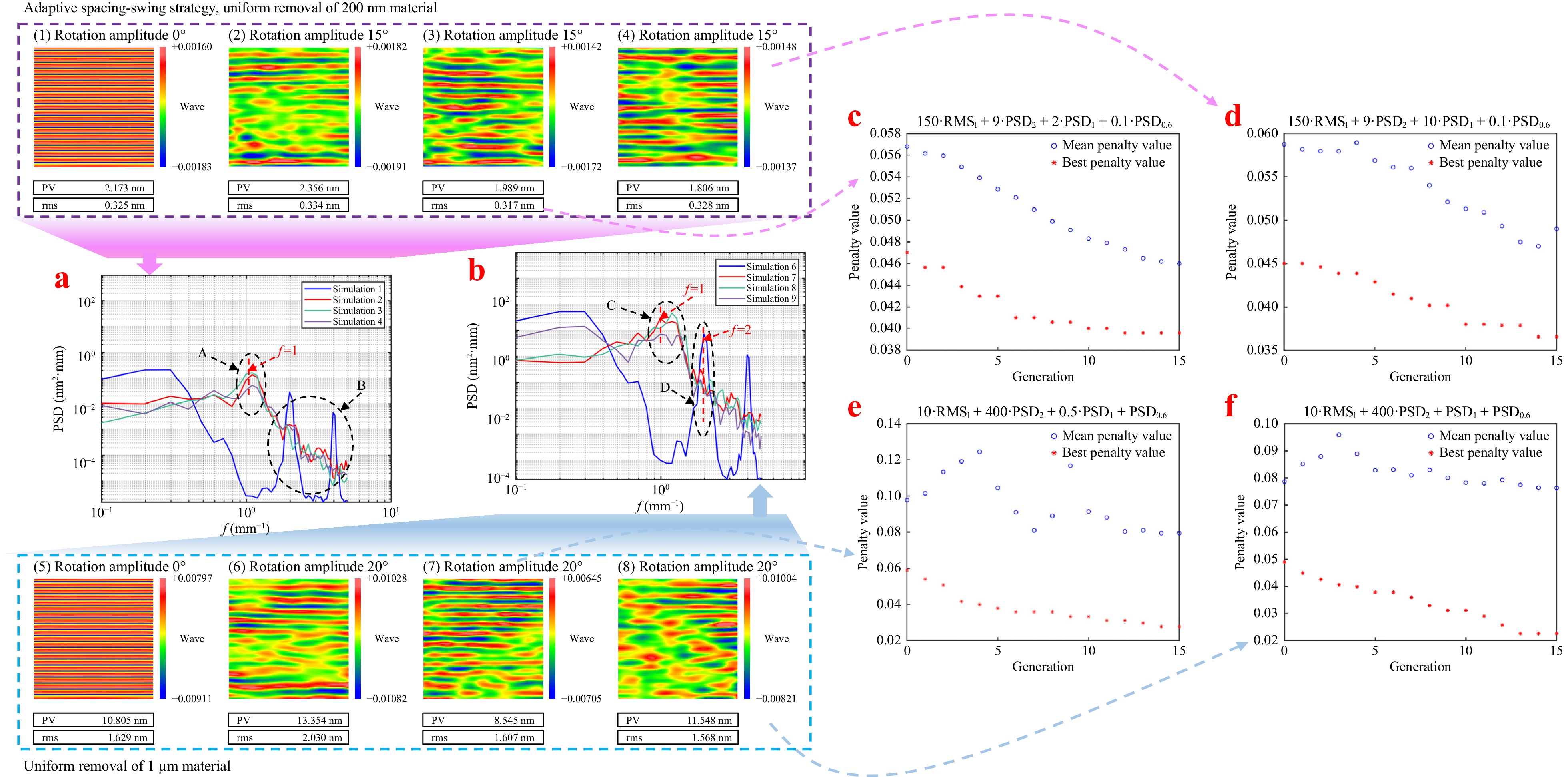
Fig. 9 MSF error and MSF PSD results of CSMRF simulation under the adaptive spacing-swing spiral strategy.
As shown in Fig. 9c-f, the algorithm steadily progressed toward optimizing our initially defined fitness function throughout the search for an optimal solution. Under the combined influence of the adaptive spacing-swing spiral strategy, the RMS value of the MSF on the surface can achieve even lower values than that obtained through uniform scanning with a fixed line spacing of 0.5 mm, effectively controlling the MSF ripple errors. With the application of the aforementioned optimization algorithm, when the fitness function constrains the RMS of the MSF, comprehensive suppression of MSF errors on the surface can be accomplished at the frequency points of 1, 2, and 0.6 mm−1.
When uniformly removing 200 nm of material from the surface, the optimized parameters yielded an RMS MSF of 0.317 nm, which was an improvement over the 0.326 nm observed with uniform scanning at a fixed line spacing of 0.5 mm. Similarly, when uniformly removing 1 μm of material, the optimized parameters resulted in an RMS MSF of 1.568 nm, outperforming the 1.629 nm achieved through uniform scanning. Moreover, when the fitness function emphasized the suppression of errors at the 1 mm frequency point, the PSD curves from Simulations 4 and 8 exhibited a more than five-fold reduction at this frequency compared with Simulations 2 and 6, effectively controlling the MSF error at specific frequency points. This underscores the efficacy of the method in managing errors at targeted frequencies.
-
To verify the effectiveness of the adaptive spacing-swing CSMRF method in controlling MSF errors, we conducted experiments using a homemade CSMRF machine, featuring a polishing wheel with a diameter of 200 mm, as shown in Fig. 10a. The rotation velocity of the MRF wheel was set to 200 rpm, whereas the magnetic field current, viscosity, and flow rate of the MR fluids were maintained at 8 A, 150 Pa·s, and 120 L/h, respectively. The indentation depth between the magnetorheological polished ribbon and the optical element was set to 0.2 mm.
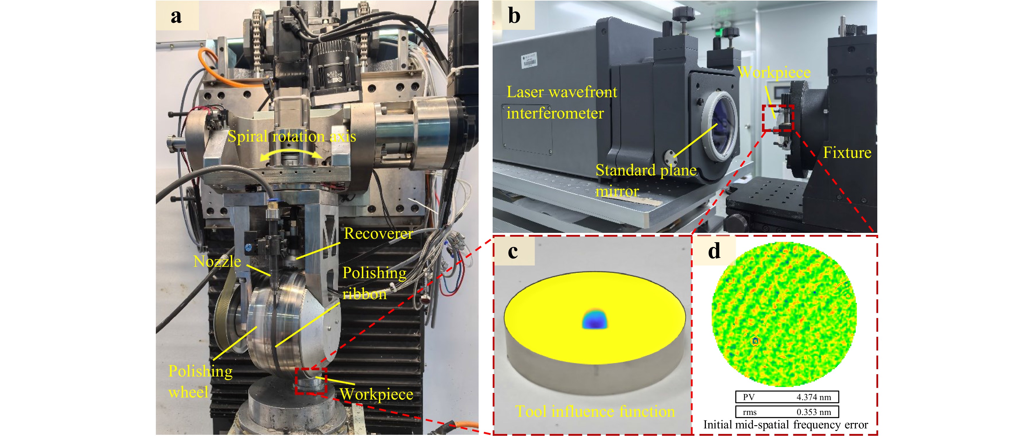
Fig. 10 Experimental device, TIF and MSF error of workpiece surface ( a ) Controllable spiral magnetorheological finishing system ( b ) Laser interferometer Zygo GPI XP ( c ) TIF obtained by experiment ( d ) Initial MSF error of workpiece surface
The shapes and sizes of the TIF obtained from the experiments are depicted in Fig. 10c. The fused-silica component used in the experiment was identical to that used in the NIF, with the material sourced from Corning 7980. Surface shape errors were measured using a laser interferometer (Zygo GPI XP), and the measurement results were filtered with a band-pass filter in the frequency range of 0.1 to 5 mm−1 to extract the MSF surface error, as shown in Fig. 10b. A 10 mm × 10 mm area was selected for the analysis. In total, eight experiments were conducted using the parameters outlined in Table 5.
Experiment
numberLine-feed spacing
(mm)Depth of material
removal (nm)Range of spiral
angle (°)Fitness function RMS MSF
error (nm)1 1 1000 0 NaN 4.429 2 0.5 1000 0 NaN 0.608 3 0.5 1000 5 NaN 0.502 4 0.5–1 1000 0 NaN 2.096 5 0.5–1 1000 5 NaN 1.616 6 0.5–1 1000 20 NaN 1.557 7 0.5–1 1000 20 10·RMSl + 400·PSD2 + 0.5·PSD1 + PSD0.6 0.762 8 0.5–1 1000 20 10·RMSl + 400·PSD2 + PSD1 + PSD0.6 0.547 Table 5. Experimental conditions and RMS MSF error results of the adaptive spacing-swing CSMRF method in controlling MSF errors
-
First, experiments were conducted using eight fused silica flat elements with a diameter of 50 mm. To verify the effectiveness of the adaptive spacing-swing CSMRF strategy in controlling the MSF and specific frequency errors, we performed eight comparative experiments, as detailed in Table 5. All eight flat elements were polished and shaped using a single-axis polishing machine, resulting in initial surfaces with high quality, where the RMS values were generally below λ/20 (λ = 632.8 nm). The MSF errors in the 0.1–5 mm−1 range were approximately 0.3 to 0.4 nm RMS, indicating that the surface MSF error was not significant. Figs. 11, 12 show the MSF errors for the eight groups of experiments, along with the comparative results of the MSF PSD curves for these groups. Table 6 summarizes and explains the advantages and disadvantages of polishing under different experimental strategies.
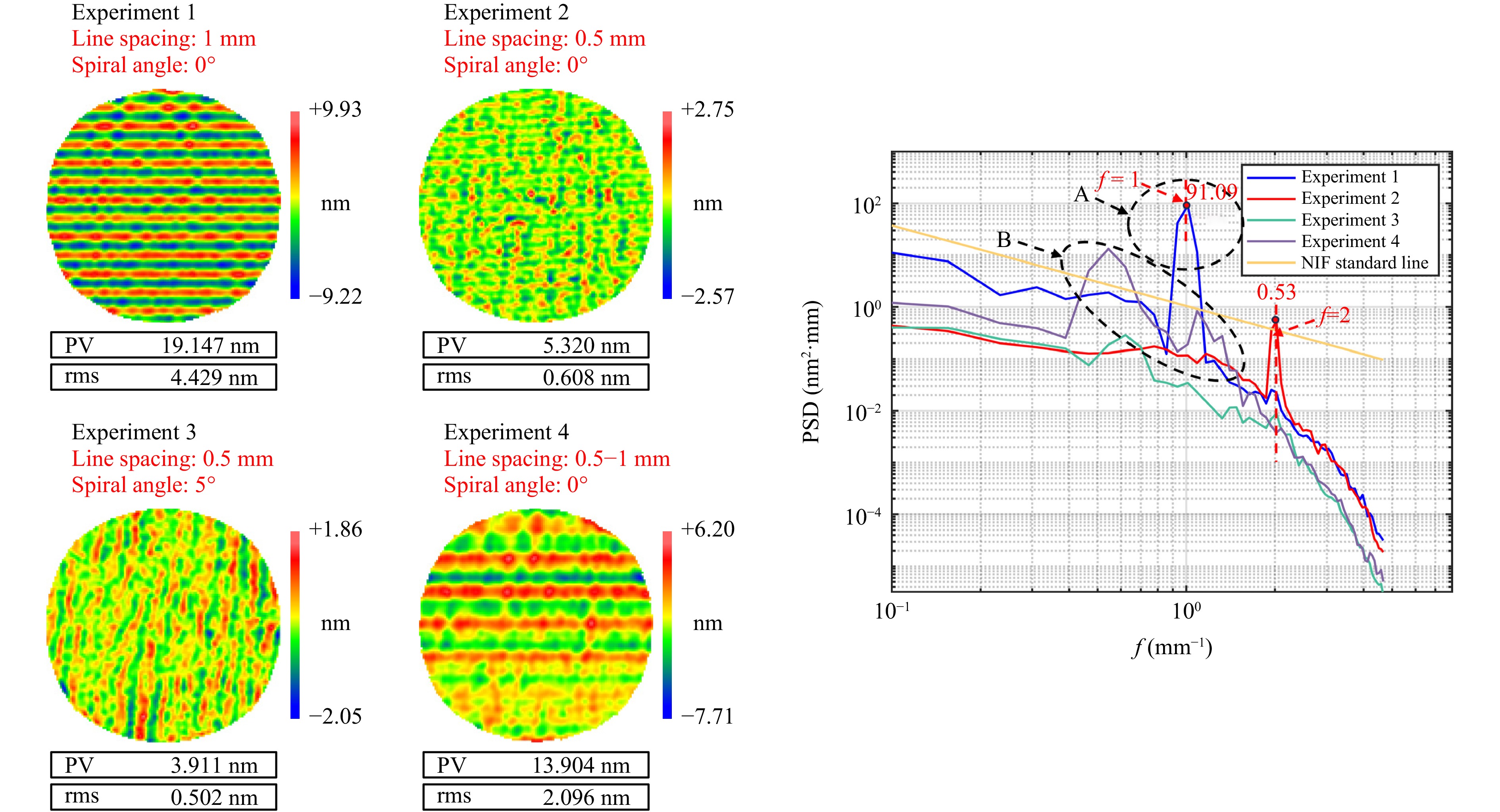
Fig. 11 Comparative experimental results of the MSF and PSD curve of magnetorheological polishing under the conventional scanning, controllable spiral, and time-varying spacing strategies.
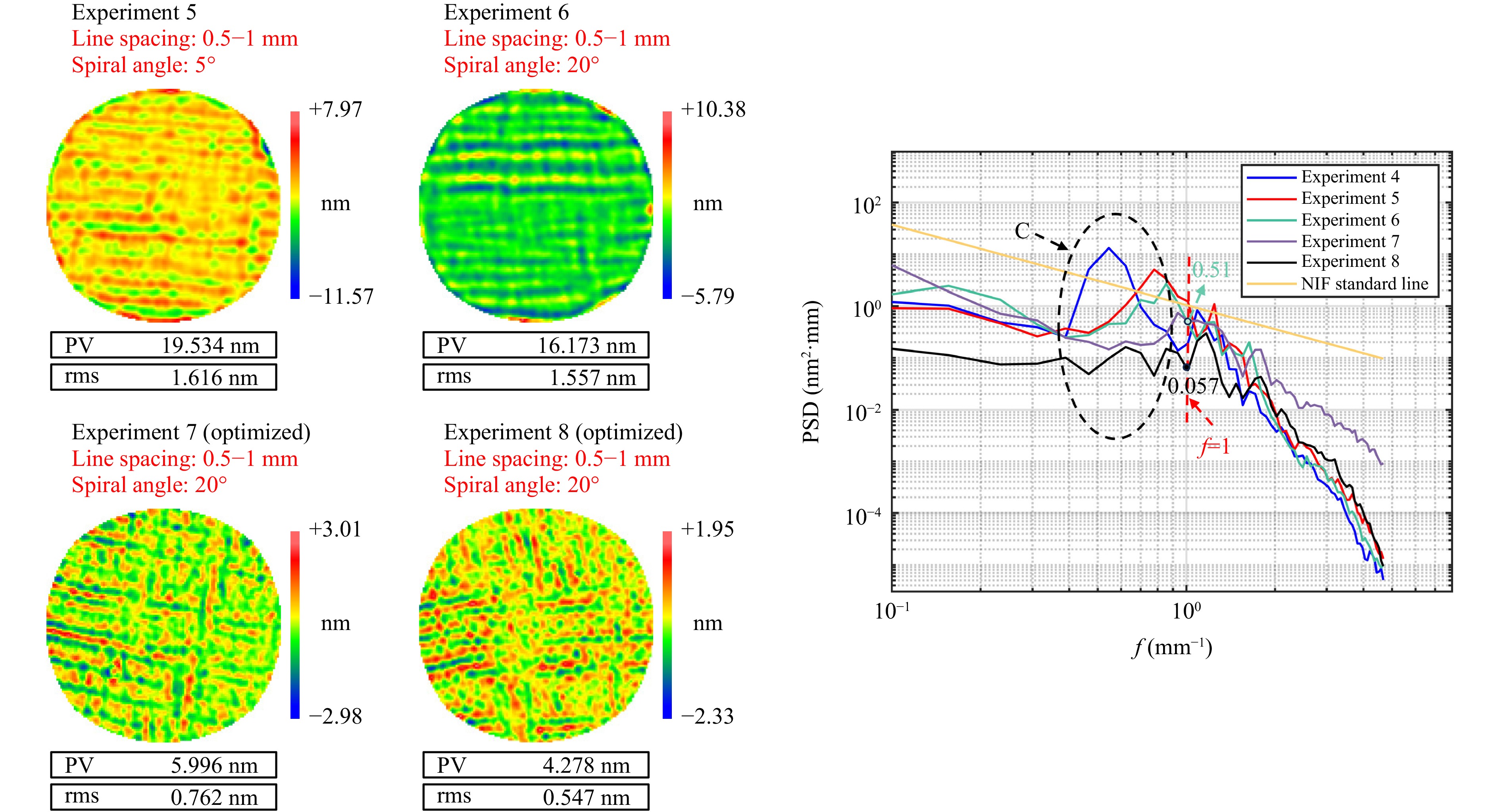
Fig. 12 Comparative experimental results of the MSF and PSD curve of magnetorheological polishing under the adaptive spacing-swing CSMRF method
Experiment number Processing strategy Advantages Disadvantages 1 Fixed line spacing (1 mm)
Not spiralRequires lower positioning accuracy and dynamic performance of the machine tool and is easy to implement Produces large periodic MSF ripples 2 Fixed line spacing (0.5 mm)
Not spiralCan significantly reduce the amplitude of periodic ripples Requires higher positioning accuracy and dynamic performance of the machine tool and still produce periodic MSF ripples 3 Fixed line spacing (0.5 mm)
Spiral angle 5°Can further smooth the ripple based on reducing the amplitude of the periodic ripple When the material removal is significant, it is challenging to completely smooth the ripple by rotating only 5° 4 Random line spacing
(0.5–1 mm) Not spiralCan disrupt the periodic structure of ripples and disperse the characteristic peaks of PSD curve to other frequencies Can only disrupt the ripple period and cannot reduce the amplitude of the ripple 5 Random line spacing
(0.5–1 mm) Spiral angle 5°Provides some smoothing ability based on Experiment 4 Still cannot smooth the deeper ripple amplitude 6 Random line spacing
(0.5–1 mm)
Spiral angle 20°Provides stronger smoothing ability based on Experiment 5 Without the optimization of line spacing and spiral angle, the RMS value of MSF error is large 7 Adaptive line spacing (0.5–1 mm)
Spiral angle 20°Based on the iterative optimization of genetic algorithm, the objective function is to set the minimum MSF error, resulting in a smaller MSF error The algorithm requires multiple iterations and additional computation time 8 Adaptive line spacing (0.5–1 mm)
Spiral angle 20°Based on Experiment 7, by modifying the objective function, greater weight is assigned to the specific frequency f=1 mm−1 to regulate the specific frequency error The algorithm requires multiple iterations and additional computation time Table 6. Advantages and disadvantages of polishing using different experimental conditions.
According to Fig. 11, under the original fixed spacings of 1 and 0.5 mm, characteristic periodic MSF ripples were observed, resulting in prominent peaks in the PSD curve. The proposed time-varying spacing method successfully dispersed these periodic characteristics; however, the RMS MSF did not increase significantly, as shown for Experiment 4 in Fig. 11. By employing the time-varying swing-controllable spiral polishing method with an additional 5° spiral angle at a 0.5 mm spacing, we significantly suppressed the MSF ripples, improving the RMS MSF from 0.608 to 0.502 nm, thus achieving the smoothing effect predicted by the simulations. When using the novel adaptive spacing-swing CSMRF method, the introduction of a spiral angle resulted in a slight increase in the RMS MSF compared with using the time-varying spacing alone. However, when the non-negative gradient-constrained dwell-time optimization algorithm was applied based on genetic algorithms for specific error optimization, the RMS MSF error improved significantly, reaching levels comparable to those achieved with a 5 mm spacing. This further validated the efficacy of the algorithm proposed in this study.
To provide a more intuitive understanding of the error distribution across different frequency bands, we analyzed the PSD curves from the eight experimental groups. As shown in Region A of Fig. 11, the fixed spacing method produced significant characteristic peaks, indicating the presence of MSF ripple errors. In Region B, while the time-varying spacing method eliminated these periodic characteristic peaks, it inadvertently generated new high points in other frequency bands. The introduction of the spiral angle effectively suppressed the periodic peaks associated with the 0.5 mm fixed spacing, although they remained present, as observed in Experiments 2 and 3. Additionally, the spiral angle effectively smoothed out the new high points introduced by the time-varying spacing, corresponding with our simulations and theoretical analysis.
As shown in Region C of Fig. 12, our optimization algorithm effectively smoothed the high-frequency points generated by adaptive spacing. When the fitness function increased the optimization weight at f = 1, the value of the PSD curve at this frequency decreased by a factor of 10. Compared with our conventional scanning strategy (Experiment 1), the peak value of the PSD feature decreased by 99.938%. Moreover, the mid-frequency ripple error caused by convolution in the sub-aperture polishing was entirely eliminated. The MSF PSD curves processed through optimal control all fell within the standard line specified by the NIF, enabling fast and efficient control of mid-frequency errors during the single magnetorheological polishing process.
-
In this study, we conducted theoretical calculations and simulation analyses to explore the generation mechanisms of mid-spatial frequency errors in magnetorheological finishing. We developed a novel strategy for suppressing MSF errors through adaptive spacing-swing CSMRF, complemented by a multi-objective control optimization dwell-time algorithm based on genetic algorithms. The aim of this research was to enhance the understanding of the control mechanisms for MSF ripple errors and specific MSF band errors in CSMRF. The main conclusions are summarized as follows:
1. By analyzing the spectral changes during the time-varying spacing and TIF spiral swing process, we studied the effects of these methods on MSF ripple errors, demonstrating their complementary roles in controlling MSF ripples.
2. We developed a dwell-time solving algorithm based on the non-negative-gradient constraint of the Lagrange regularization method, combined with a genetic algorithm. This approach enables the determination of adaptive row spacing and swing angles for multi-objective optimization of dwell time, effectively controlling frequency and MSF errors under specific targets.
3. Both theoretical simulations and experimental results indicated that the proposed adaptive spacing-swing controllable spiral magnetorheological polishing strategy, alongside the genetic algorithm-based dwell-time optimization, can effectively control specific MSF errors. This approach can be readily adapted to other controllable TIF polishing methods.
Experimental results confirmed that the novel CSMRF method effectively regulates MSF errors, demonstrating high MSF error control capabilities within inertial confinement fusion systems. This method achieves efficient control of MSF errors using a single magnetorheological polishing process. Additionally, owing to the adjustable posture of the TIF and the multidirectional scratching characteristics of the polishing particles, this method exhibits potential adaptability for complex surface shapes and ultra-smooth surfaces. Future research will investigate the full-band error regulation capabilities of this polishing tool and extend its applications to scenarios requiring even higher precision.
-
The presented work was funded by the National Natural Science Foundation of China (62175259), Strategic Priority Research Program of the Chinese Academy of Sciences (No. XDA25020317), Science and Technology Innovation Program of Hunan Province(2022RC1138), Science and Technology Innovation Program of Hunan Province (2023JJ30079), Science and Technology Innovation Program of Hunan Province (2024JJ6460), and Graduate Science and Technology Innovation Project of Hunan Prov. (CX20230019). The authors acknowledge the financial support.
Novel suppression strategy of mid-spatial-frequency errors in sub-aperture polishing: adaptive spacing-swing controllable spiral magnetorheological finishing (CSMRF) method
- Light: Advanced Manufacturing , Article number: (2025)
- Received: 22 October 2024
- Revised: 21 April 2025
- Accepted: 19 May 2025 Published online: 10 October 2025
doi: https://doi.org/10.37188/lam.2025.045
Abstract: Computer-controlled sub-aperture polishing technology is crucial for achieving high-precision optical components. However, this convolution material removal method introduces a significant number of mid-spatial frequency (MSF) errors, which adversely impact the performance of optical systems. To address this issue, we propose a novel controllable spiral magnetorheological finishing (CSMRF) method that disrupts the mechanism of conventional constant tool influence function (TIF) convolution material removal. In this study, we leverage the advantages of a time-varying spacing strategy and theoretically analyse how time-varying spacing, combined with the spiral swing process of the TIF, mitigates MSF ripple errors. The time-varying spacing method highlights the importance of controlling the characteristic frequency, while the CSMRF method demonstrates a smoothing effect on the errors within the MSF band. Our findings confirm that time-varying spacing and spiral swinging have complementary effects in managing MSF errors. Furthermore, by constraining the MSF error and specific frequency error, we identify the optimal combination of adaptive spacing and spiral angle using a genetic algorithm. On this basis, the MSF error is evaluated by combining the characteristic dwell time solution algorithm. Using the inertial confinement fusion optical element as an example, we observe a 99.938% reduction in the amplitude of the PSD curve of the mid-frequency ripple error with a spatial period of 1 mm, while the mid-frequency PSD curve remains within the standard line. Therefore, the proposed method can effectively control the specific MSF error distribution. This variable convolution kernel (TIF) sub-aperture polishing method provides a new idea for full-band cooperative error control.
Research Summary
Novel sub-aperture polishing method: controllable spiral magnetorheological finishing
Ultra-high-precision, computer-controlled sub-aperture polishing technology is crucial for achieving full-band, high-precision optical components. However, the existing sub-aperture polishing technology introduces a significant number of mid-spatial frequency(MSF) errors, which adversely impact the performance of optical systems.To address this problem, Feng Shi and Ci Song from China’s National University of Defense Technology and colleagues report a novel sub-aperture polishing method: controllable spiral magnetorheological finishing method that disrupts the mechanism of conventional constant tool influence function (TIF) convolution material removal.The erasing characteristics of the spiral time-varying TIF on MSF error are found. The sub-aperture polishing method incorporating a variable TIF, as developed by the research team, demonstrates extensibility to various sub-aperture polishing technologies. These enhanced techniques enable the implementation of time-variant TIF, thereby establishing a novel paradigm for comprehensive frequency-band collaborative error regulation in sub-aperture polishing systems.
Rights and permissions
Open Access This article is licensed under a Creative Commons Attribution 4.0 International License, which permits use, sharing, adaptation, distribution and reproduction in any medium or format, as long as you give appropriate credit to the original author(s) and the source, provide a link to the Creative Commons license, and indicate if changes were made. The images or other third party material in this article are included in the article′s Creative Commons license, unless indicated otherwise in a credit line to the material. If material is not included in the article′s Creative Commons license and your intended use is not permitted by statutory regulation or exceeds the permitted use, you will need to obtain permission directly from the copyright holder. To view a copy of this license, visit http://creativecommons.org/licenses/by/4.0/.

 DownLoad: