


-
As a kind of 3D display technology, holographic 3D display technology is an important technology that has undergone rapid development globally and has become a research hotspot. It has great application prospects in education, culture and entertainment, military affairs, medical treatment, and other fields1-4. An ideal holographic 3D display should be able to provide viewing experience with wide viewing angle, full color, and low speckle noise5-6. However, the viewing angle of holographic 3D display is far from meeting the viewing needs by resorting to the existing strategies7-9. At present, an important challenge of holographic 3D display is the large viewing angle display.
Many researchers have introduced time or spatial multiplexing methods based on spatial light modulator (SLM) to expand the viewing angle of holographic 3D display10-15. Among them, the time multiplexing method has high requirements for the refresh rate of SLM, while the spatial multiplexing method using multiple curved SLMs will increase the cost and complexity of the system. In 2017, researchers proposed a method to generate a holographic 3D image by controlling the volume speckle field, which was expected to achieve a 60° display viewing angle16. In 2019, based on the ultra-high-capacity aperiodic photon sieve, a wide viewing angle holographic display system was proposed17. In addition, the metasurface device with sub-wavelength modulation capability was also used in holographic display system to enlarge the viewing angle18-21.
Moreover, other researchers proposed using holographic optical elements in the optical system to realize large viewing angle 3D display22-24. However, there are still difficulties and challenges in the processing of metasurface structures and holographic optical elements25-27. Recently, liquid crystal devices have provided new opportunities for the development of holographic 3D display because of their advantages of polarization selectivity and adjustable voltage28-32. For example, researchers used the liquid crystal polymer-based Dammann grating to expand the viewing angle of holographic near-eye 3D display33. Some researchers used liquid crystal lens to realize holographic zoom display34-35. In 2022, a tunable liquid crystal grating was used in the holographic display system, and the viewing angle of the system reached 57.4°36. However, we found that the diffraction of image points in the previous large viewing angle holographic 3D display system did not fully reach the maximum diffraction range of the SLM. Therefore, the large viewing angle holographic 3D display technology needs to be further developed.
Here, a large viewing angle holographic 3D display system is proposed, as shown in Fig. 1. The core of this system comprises the SLMs on which a large-size hologram is loaded and liquid crystal grating. A maximum diffraction modulation scheme is proposed to enlarge the viewing angle. For a 3D object, by determining the effective viewing area of the reconstructed image, we obtain the maximum diffraction fringe of each image point under the limited diffraction condition of SLM. Based on this, the calculation method of large-size hologram is proposed. As shown in the explosion diagram in Fig. 1, liquid crystal grating has a special structure, which can provide the secondary diffraction of the reconstructed image to realize the continuous expansion of holographic viewing angle. The proposed maximum diffraction modulation scheme enables the viewing angle of the system to be enlarged considerably. The proposed system has a decent display effect and broad application prospects.
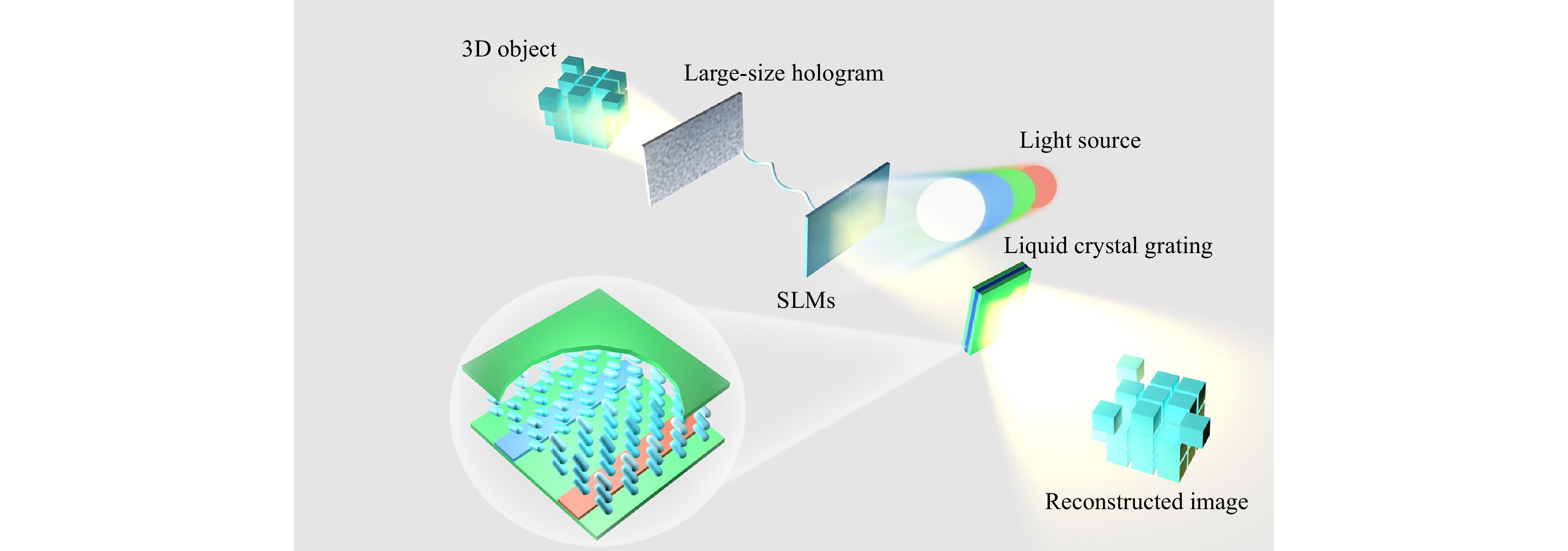
Fig. 1 Concept of the proposed system.
-
As shown in Fig. 2, the proposed system consists of a laser, a beam expander, a collimating lens, a beam splitter (BS), two SLMs, lens I, lens II, a filter, a liquid crystal grating, a polarization light valve, and a signal controller. Lens I, lens II, and the filter form a 4f system. The laser, beam expander and collimating lens are used to generate the collimated incident light, which irradiates SLM I and SLM II after passing through the BS. The large-size hologram of the 3D object is loaded on SLM I and SLM II, respectively. The diffracted light passes through lens I after being reflected by the SLMs. The filter is positioned behind lens I and is used to eliminate the high-order diffracted light. Liquid crystal grating is located on the back focal plane of lens I and on the front focal plane of lens II. The polarization light valve behind liquid crystal grating is used to adjust the intensity of light and control the passage of light of different diffraction orders. Two SLMs with the same model are used to form a large-size SLM. When the light illuminates the large-size hologram, the holographic image can be reconstructed. After the holographic image passes through lens I and the filter, it converges at the spectral position and forms a point. This point is re-modulated by liquid crystal grating to expand the viewing angle and finally converted into reconstructed image through lens II. Then, the reconstructed image is captured by a camera.
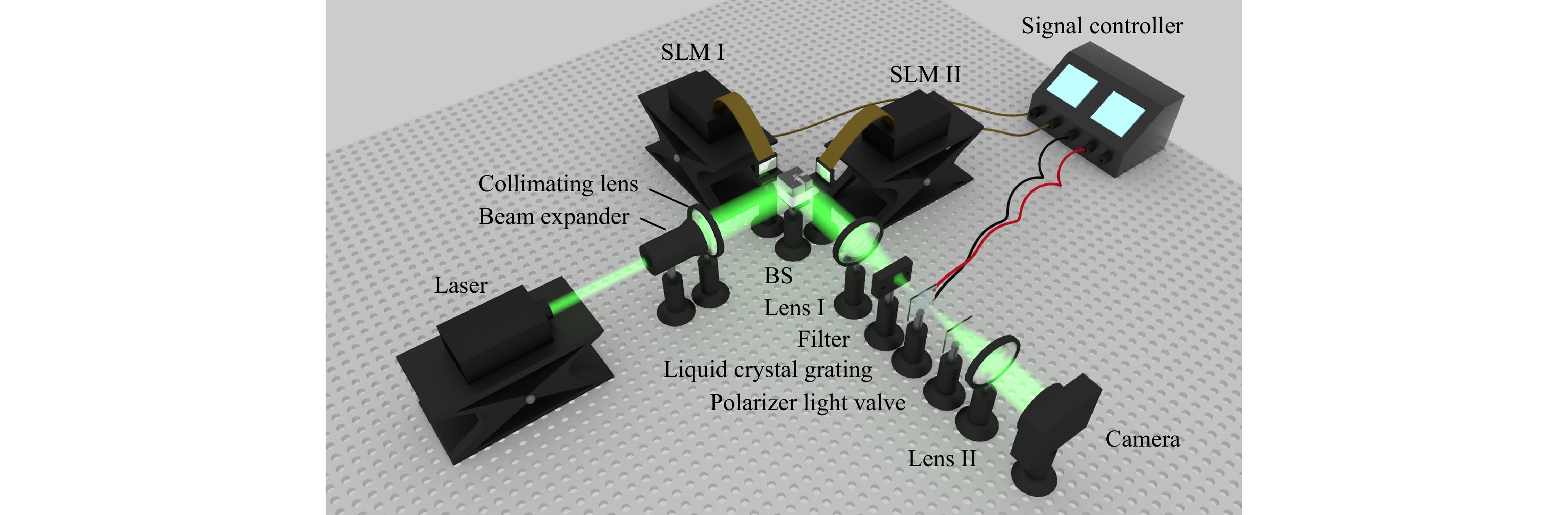
Fig. 2 Structure of the proposed system.
The realization process of the holographic 3D display with large viewing angle is shown in Fig. 3. First, a 3D object can be regarded as a series of object points, wherein each object point corresponds to a diffracted image point. Notably, the holographic interferogram of a single image point is dictated by the maximum diffraction angle of the SLM, and then the effective viewing area of the reconstructed image is determined according to the whole size of the object. In this case, the large-size hologram of the whole 3D object can be formed by analyzing the interferogram of all object points (see Step 1). Second, two SLMs are seamlessly spliced so that the large-size hologram can be loaded on the SLMs. A collimated coherent light is used to irradiate the large-size hologram for reconstruction (see Step 2). Third, the stray light crosstalk caused by the pixelated structure of SLMs is filtered by a 4f system (not shown here). At this moment, a liquid crystal grating with specially designed structure is placed in the middle frequency spectrum of the 4f system. The reconstructed image of holographic 3D display is then subjected to a secondary diffraction modulation by liquid crystal grating. Consequently, the secondary diffraction image with a continuous viewing angle can be generated, and the continuous expansion of the viewing angle can be realized (see Step 3).
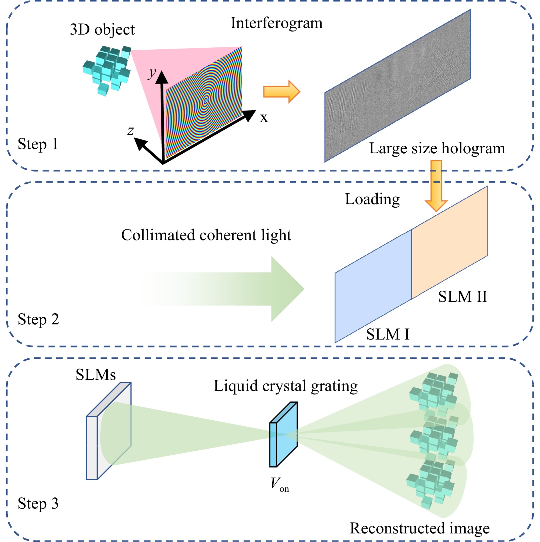
Fig. 3 Realization process of the holographic 3D display with a large viewing angle.
-
As a comparison, we first overview the traditional hologram, as shown in Fig. 4a, b. The size of the recorded 3D object is W, the coordinate origin is in the center of the SLM. The leftmost and rightmost object points of the 3D object are marked as A and B, respectively. The distance between the 3D object and the SLM is Z, and the size of the SLM is H. R is the viewing distance. For the leftmost image point A’, the maximum diffraction angle of the SLM is assumed φ, and the associated viewing area is VA (Fig. 4a). It is also clear that the maximum diffraction angle α of image point A’ is usually smaller than φ for an object of a certain size (Supplementary material S1). Furthermore, the viewing areas of both A’ and B’ are demonstrated (Fig. 4b), and we can observe that the intensity patterns extend to a certain extent. However, only the overlapping diffraction area of two image points can reconstruct the complete 3D object, and this overlapping diffraction area is called the effective viewing area of the reconstructed image.
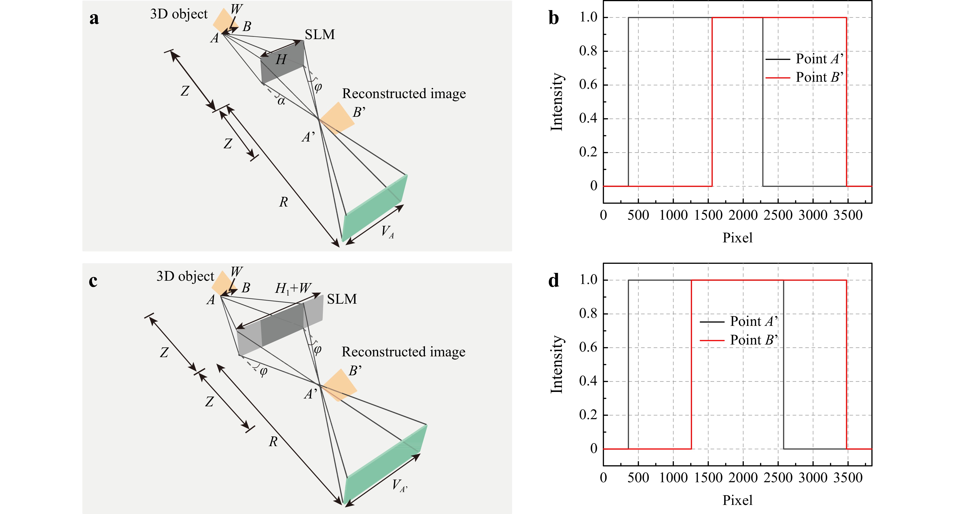
Fig. 4 Generation mechanism of the large-size hologram. a Diffraction analysis of the traditional hologram. b Light distribution of the leftmost and rightmost image points by using the traditional hologram at R=132 mm. c Diffraction analysis of the large-size hologram. d Light distribution of the leftmost and rightmost image points by using the large-size hologram at R=132 mm.
To increase the viewing angle, the size of the SLM needs to be expanded, and the large-size hologram is simultaneously required. Therefore, we first consider the maximum diffraction angle φ instead of the size of the SLM. In the proposed system, all diffraction angles from the left and right sides of the hologram to the image point A’ are recorded as φ, as shown in Fig. 4c. At this time, the diffraction area of image point A’ is VA’. Obviously, the display angle of a single image point is larger than that of the traditional hologram. We start with a preliminary numerical calculation to verify the advantage of the large-size hologram. In the simulation, the resolution of recorded object is assumed 600×600, diffraction distance is 66 mm, and resolution of the SLM is 1920×1080. The viewing areas corresponding to image points A’ and B’ are shown in Fig. 4d. Evidently, at the same viewing distance, Fig. 4d can cover more pixels, so the large-size hologram has a wider viewing angle than the traditional hologram.
According to the Fresnel diffraction theory and the geometric relationship of the reconstructed image, we can derive the diffraction angles as follows:
$$ \varphi {\text{ = }}{\sin ^{ - 1}}(\lambda /2p) $$ (1) where λ is the wavelength, and p is the pixel size of the SLM. To ensure that a complete 3D image is seen in the viewing area, the critical point of the recorded object must be calculated. The hologram size H1 of image point A’ and the hologram size HD of the whole 3D object are calculated as follows:
$$ H_{1}=2Z\cdot \tan\varphi $$ (2) $$ {H_{\text{D}}} = {H_1} + W $$ (3) Accordingly, the viewing angle of the reconstructed image is expanded as β=2φ. Finally, two SLMs are seamlessly spliced to form a large-size SLM array. The large-size hologram is equally divided into two sub-holograms and loaded on two SLMs, respectively.
-
After clarifying the conceptual engineering of the large-size hologram, we proceed with the demonstration of liquid crystal grating. Liquid crystal grating is utilized to tune the first-order reconstructed image of the holographic 3D display. The structure of liquid crystal grating is shown in Fig. 5, which includes the upper glass substrate, liquid crystal layer, pixel strip electrodes, common strip electrodes, and lower glass substrate. The inner surfaces of the upper and lower substrates are coated with polyimide films and rubbed in the same direction perpendicular to the bottom strip ITO electrodes. Here, w1 is the width of the pixel strip electrode, w2 is the width of the common strip electrode, l is the gap between the pixel and common strip electrodes, and h is the thickness of the liquid crystal layer. Notably, when the voltage is applied to the pixel strip electrodes, the pitch of liquid crystal grating d is w1+l, and a surrounding electric field is formed between the pixel and common strip electrodes.
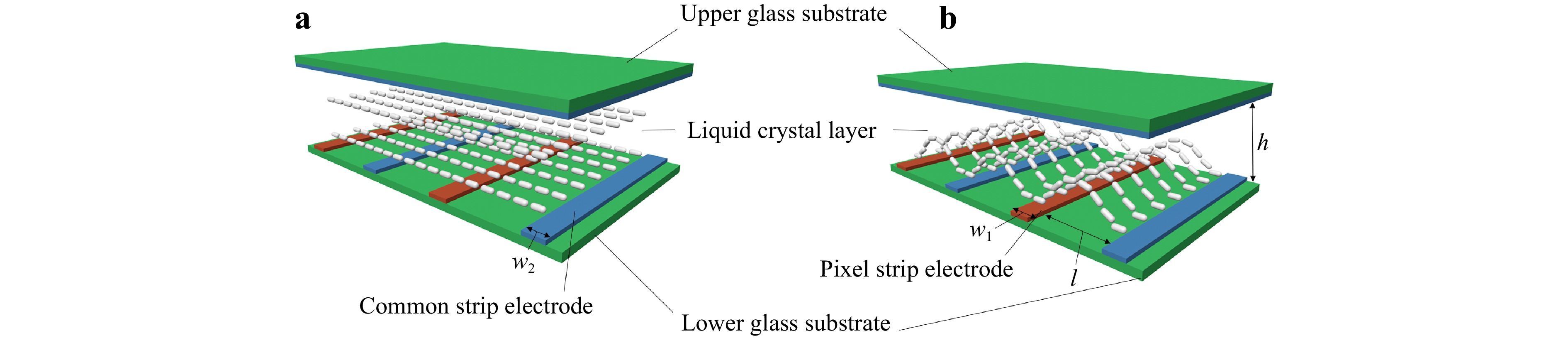
Fig. 5 Structure of liquid crystal grating. a Distribution of the liquid crystal molecules when the voltage is turned off. b Distribution of the liquid crystal molecules when the voltage is turned on.
The surrounding electric field induces the pointing deflection of the liquid crystal molecules, thus forming a center-symmetric gradient refractive index distribution and diffracting the rays incident on the liquid crystal layer. When liquid crystal grating is in the voltage-off state (Fig. 5a), only the first-order reconstructed image can pass through liquid crystal grating, and hence, the observer can see the holographic reconstructed image with the viewing angle of 2φ. On the contrary, when the voltage is applied to the electrodes (Fig. 5b), N secondary diffraction images are produced by the first-order image with different diffraction angles. Once both the size and diffraction distance of the reconstructed image are determined, the viewing angle of the modulated second diffraction image is continuous by designing the parameters of liquid crystal grating. Thus, the viewing angle of the proposed system is 2φ×N.
-
In the system, the SLMs are phase-only SLMs, and the pixel size is 3.74 μm. The refresh rate and the resolution of the SLMs are 60 Hz and 3840×2160, respectively. The maximum diffraction angle of the SLM is ~4.078º according to Eq. 1. The wavelength of the collimated coherent light is 532 nm. Two SLMs with the same model are used to form a large-size SLM array. The response time of the SLMs is ~17 ms. The switch-on and switch-off time of liquid crystal grating is ~14.3 ms and ~17.9 ms, respectively (Supplementary material S2). The focal lengths of lens I and lens II are both 250 mm. The model of the camera is Canon 70D.
-
We first verify the reconstruction effect of large-size hologram, wherein the letter ‘BH’ serves as the recorded object. The resolution of the recorded object is 1920×2160, and the reconstructed distance is 15 cm. In the case of the traditional hologram, the reconstructed images at the leftmost and rightmost viewing angles are both captured by the camera, as plotted in Fig. 6a, b. We can observe the reconstructed images completely within certain areas ranging from the leftmost to the rightmost viewing angles. Unfortunately, the images will remain incomplete and even disappear outside this range.
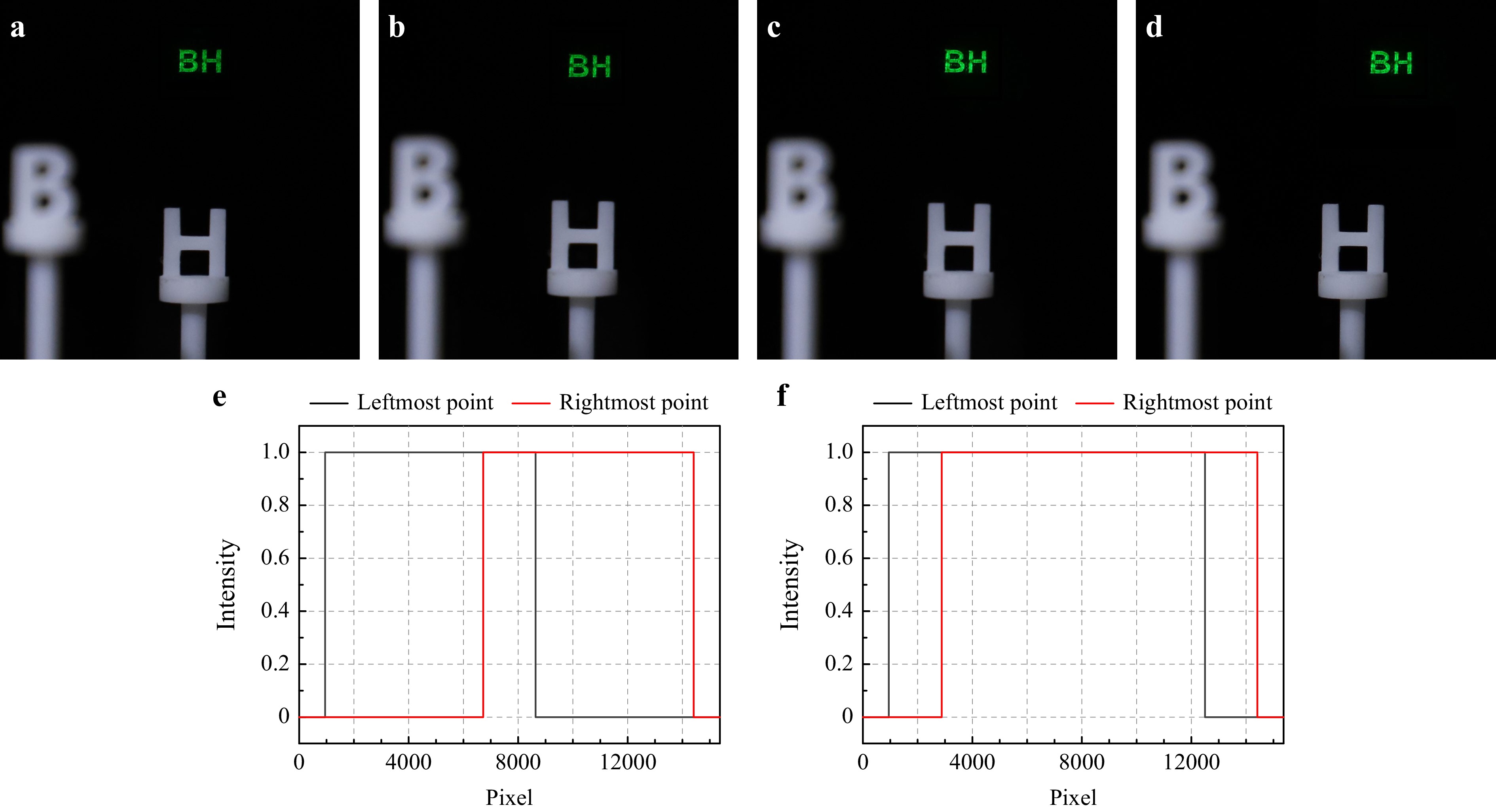
Fig. 6 Reconstructed image of the large-size hologram. a Reconstructed image at the leftmost viewing angle of the conventional hologram. b Reconstructed image at the rightmost viewing angle of the conventional hologram. c Reconstructed image at the leftmost viewing angle of the large-size hologram. d Reconstructed image at the rightmost viewing angle of the large-size hologram. e Diffraction areas of the leftmost and rightmost image points of the reconstructed image by using conventional hologram at R=450 mm. f Diffraction areas of the leftmost and rightmost image points of the reconstructed image by using large-size hologram at R=450 mm.
Meanwhile, when it comes to the maximum diffraction angle determined by the SLM, Fig. 6c, d present the reconstructed image of the large-size hologram at both the leftmost and rightmost viewing angles. The resolution of the large-size hologram is 7680×2160 under such a condition. Consequently, the large-size hologram is equally divided into two sub-holograms and loaded on the SLMs by using the signal controller. The diffraction areas of the leftmost and rightmost image points of the reconstructed image are analyzed, as shown in Fig. 6e, f. The large-size hologram has a larger reconstruction angle than that of the traditional hologram.
-
In the fabrication of liquid crystal grating, the width of the pixel strip electrode, width of the common strip electrode, and thickness of the liquid crystal layer are all 10 μm. The pitch of liquid crystal grating is 20 μm. The gap between the pixel strip electrode and common strip electrode is 10 μm. When the voltage changes, the diffraction efficiency of liquid crystal grating is also different. When the voltage (V = 7.2 V) is applied to liquid crystal grating, the incident angle of the diffracted light to liquid crystal grating is adjusted, then the number of diffracted images becomes nine. The liquid crystal molecule arrangement when a voltage is applied to liquid crystal grating is shown in Fig. 7a. At this time, the angle of liquid crystal molecules gradually increases from the middle of the electrode gap to the top of the electrode, and this angle distribution is beneficial to realizing the ideal gradient phase distribution. The top view of the electric field intensity distribution is shown in Fig. 7b. The electric field intensity decreases gradually from above the pixel electrode to above the common electrode, and the electric field intensity distribution is very uniform, which proves that liquid crystal grating has very high diffraction accuracy. The refractive index distribution of liquid crystal grating is shown in Fig. 7c, and the line focusing distribution observed under the microscope is shown in Fig. 7d.
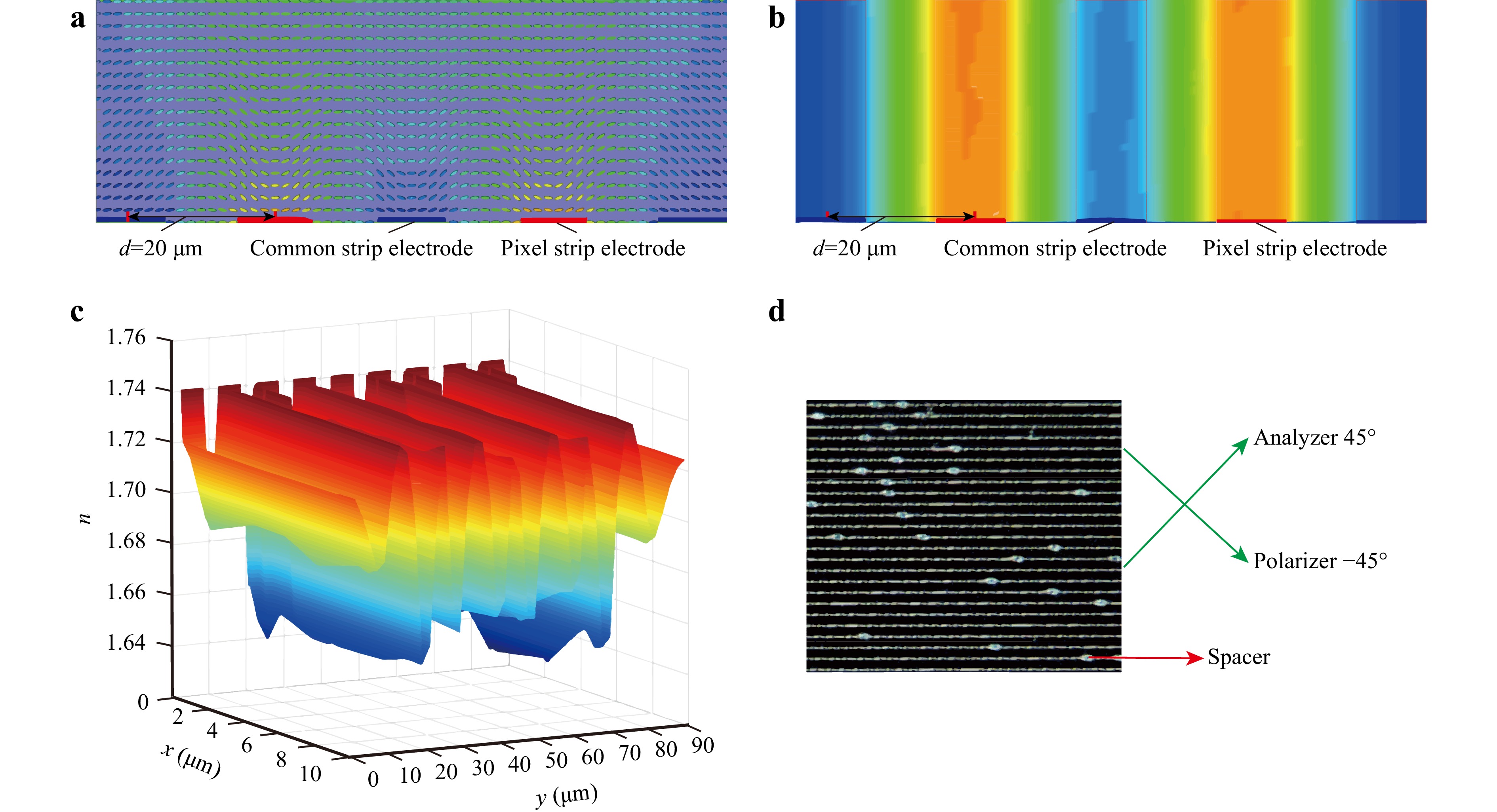
Fig. 7 Properties of liquid crystal grating. a Liquid crystal molecule pointing distribution. b Top view of the electric field intensity distribution. c Refractive index distribution of liquid crystal grating. d Liquid crystal grating placed under the orthogonal polarizer.
The first-order diffraction image of the 3D object is subjected to secondary diffraction. Notably, if the pitch of liquid crystal grating does not match the resolution and diffraction distance of the recorded 3D object, the secondary diffraction images in the observation area may be overtly sparse or the diffraction images of different orders may interfere with each other, which will affect the viewing effect to some extent.
-
To further gain insights into the viewing angle of the holographic display, Fig. 8 exhibits a series of reconstructed images without/with a voltage being applied to liquid crystal grating. The real references ‘B’ and ‘H’ models are placed at the same depth plane as the reconstructed image. The camera moves horizontally from the leftmost side of the viewing plane to the right to capture the first secondary diffraction image. When the voltage is absent, the viewing angle of the system is ~8.2º, as shown in Fig. 8a. At this time, the camera can only capture the reconstructed image within a tiny range, as the viewing angle of the reconstructed image is relatively small, i.e., the reconstructed image vanishes if the camera moves horizontally.
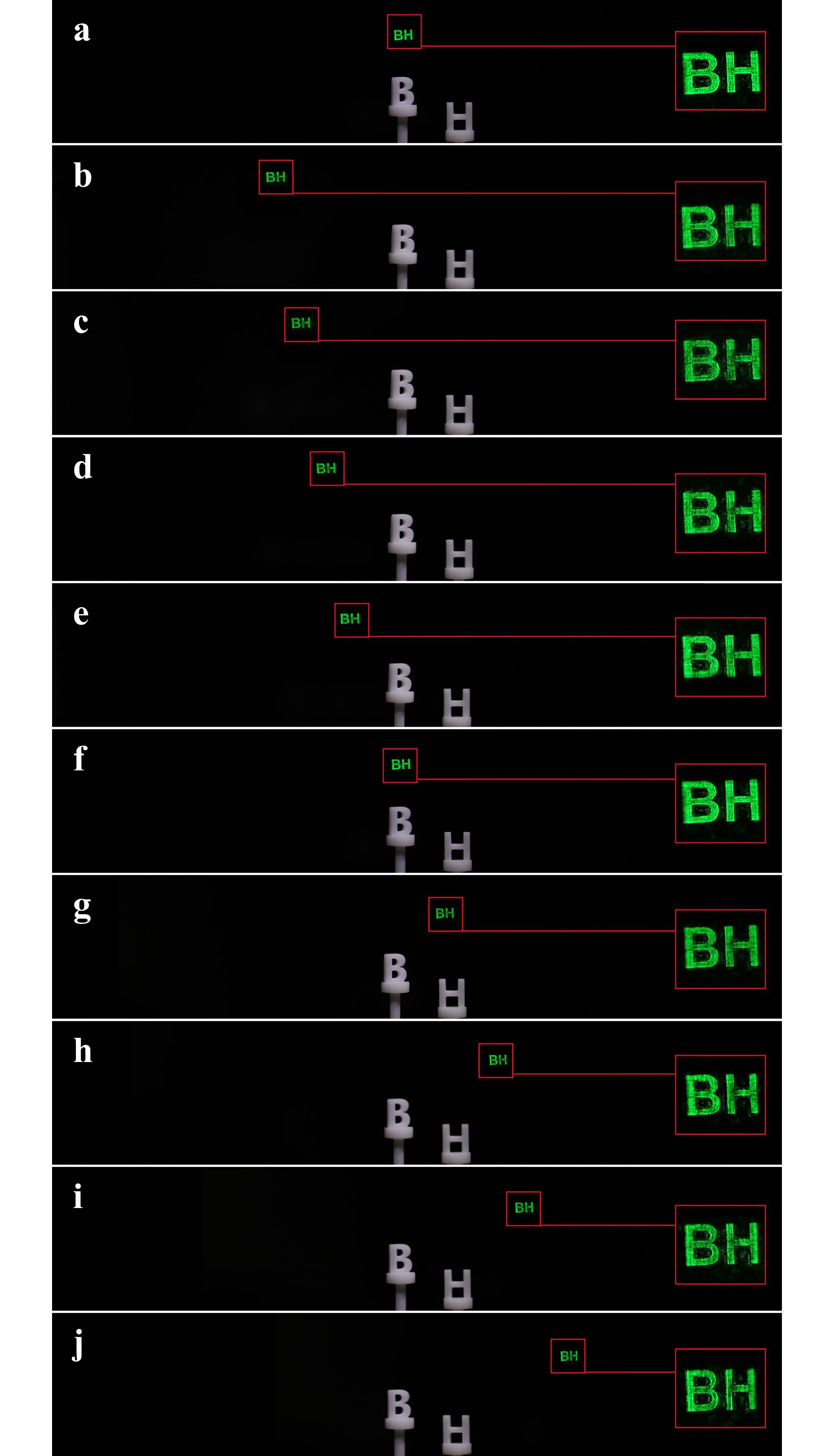
Fig. 8 Large viewing angle holographic reconstruction of 2D object. a Reconstructed image having ~8.2º viewing angle. b–j Reconstructed image having ~73.4º viewing angle.
However, the scenario is totally different when the voltage is applied to liquid crystal grating. It is manifested that nine secondary diffraction images arise by adjusting the opportune voltage (V=7.2 V). Additionally, their intensities remain uniform by changing the polarization state of the polarizer light valve. More importantly, the corresponding viewing angle of the holographic display system is enlarged to ~73.4º at this moment. The results are shown in Fig. 8b–j. To better observe the details, the reconstructed images are enlarged. The right red box of each sub-picture in Fig. 8 is an enlarged image. In the experiment, we aim to ensure the brightness uniformity of the reconstructed image by adjusting the voltage of liquid crystal grating and the polarizer light valve in the system. However, the diffraction efficiency of liquid crystal grating is the highest at the zero-order light. The diffraction efficiency of different orders with the change in voltage is recorded (Supplementary material S3). We also supplement the video of the diffraction efficiency of liquid crystal grating changing with voltage (see Video 1).
The overall efficiency of each channel decreases after the light is split and reflected in the proposed system. Therefore, the unused light beam degrades the image contrast. To eliminate the undesirable light, a filter is placed at the back focal plane of lens I to ensure that only the first-order reconstructed image can pass through the filter without a ghost. Furthermore, to verify the holographic 3D display with a large viewing angle effect, two Chinese characters with different depth information are regarded as the 3D object for recording. The resolution of the 3D object is 1920×1200. The reconstructed distances of the two characters ‘北’ and ‘航’ are 15 and 18 cm, respectively. For reference, the real model letters ‘B’ and ‘H’ are placed at different depths. The experimental results are shown in Fig. 9.
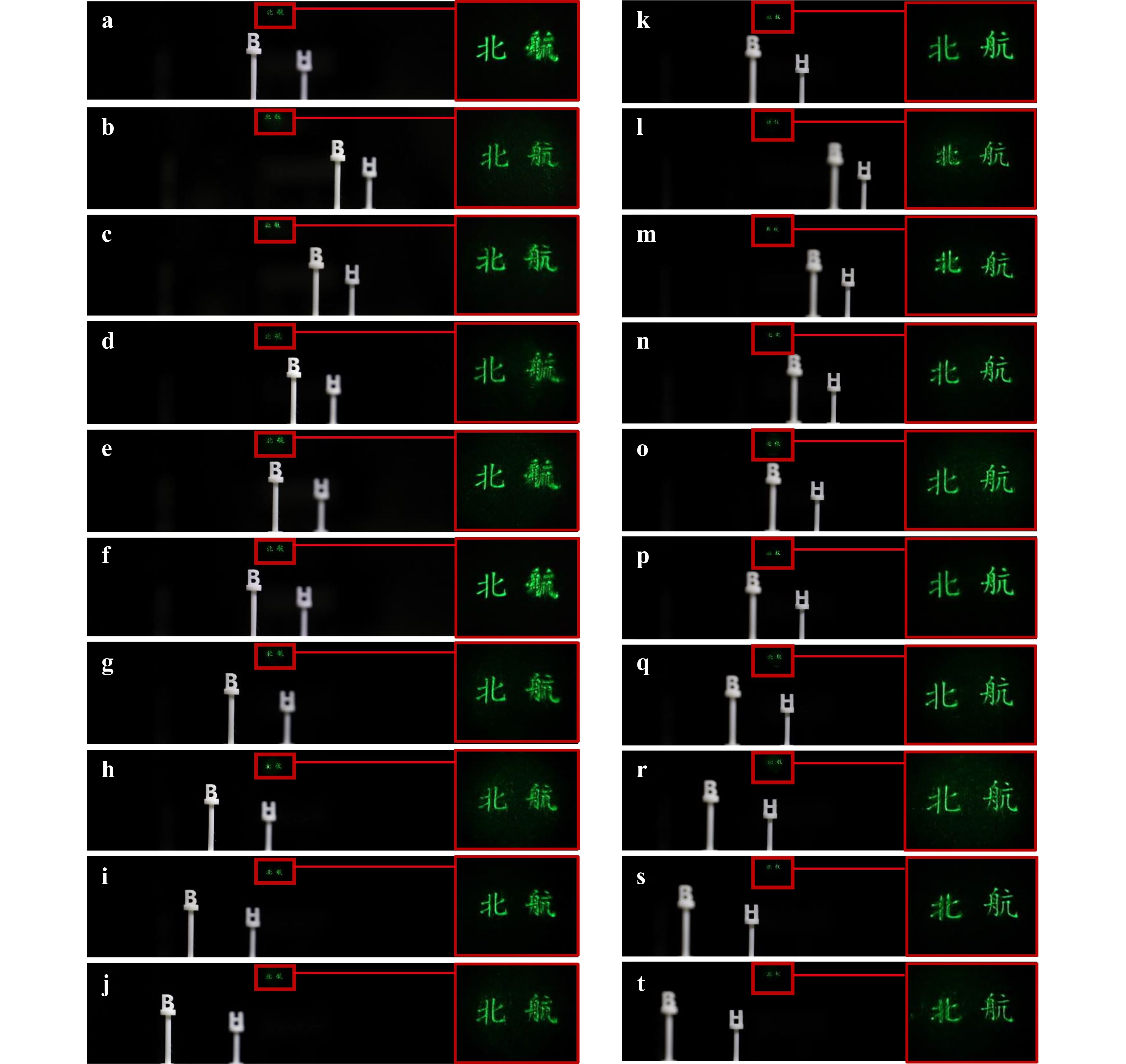
Fig. 9 Large viewing angle holographic reconstruction of 3D object. a Reconstruction result of' ‘北’ focused when no voltage is applied to liquid crystal grating. b–j Reconstruction of' ‘北’ focused when the voltage is applied to liquid crystal grating. k Reconstruction image of ‘航’ focused when no voltage is applied to liquid crystal grating. l–t Reconstruction result of' ‘航’ focused when the voltage is applied to liquid crystal grating.
Fig. 9a, k display the holographic reconstructed results when ‘北’ and ‘航’ are focused, respectively, when no voltage is applied to liquid crystal grating. At this time, the camera can only capture the reconstructed image within the viewing angle of ~8.2º. Fig. 9b–j show nine diffracted images captured with the movement of the camera focusing on ‘北’ when the voltage is applied to liquid crystal grating. After using liquid crystal grating, the viewing angle is enlarged to be ~73.4º. Likewise, the image in the red box is the magnified picture to show the details. Fig. 9l–t are the results when ‘航’ is focused.
In addition, the dynamic video of the holographic 3D reconstruction is captured (see Videos 2-3). Two groups of letters with different depth information are regarded as the 3D object for recording. The real model letters ‘B’ and ‘H’ are placed at different depths for reference. The results focused on ‘3D’ are shown in Fig. 10a–c and Video 2. The results focused on the ‘Lab’ are shown in Fig. 10d–f and Video 3.
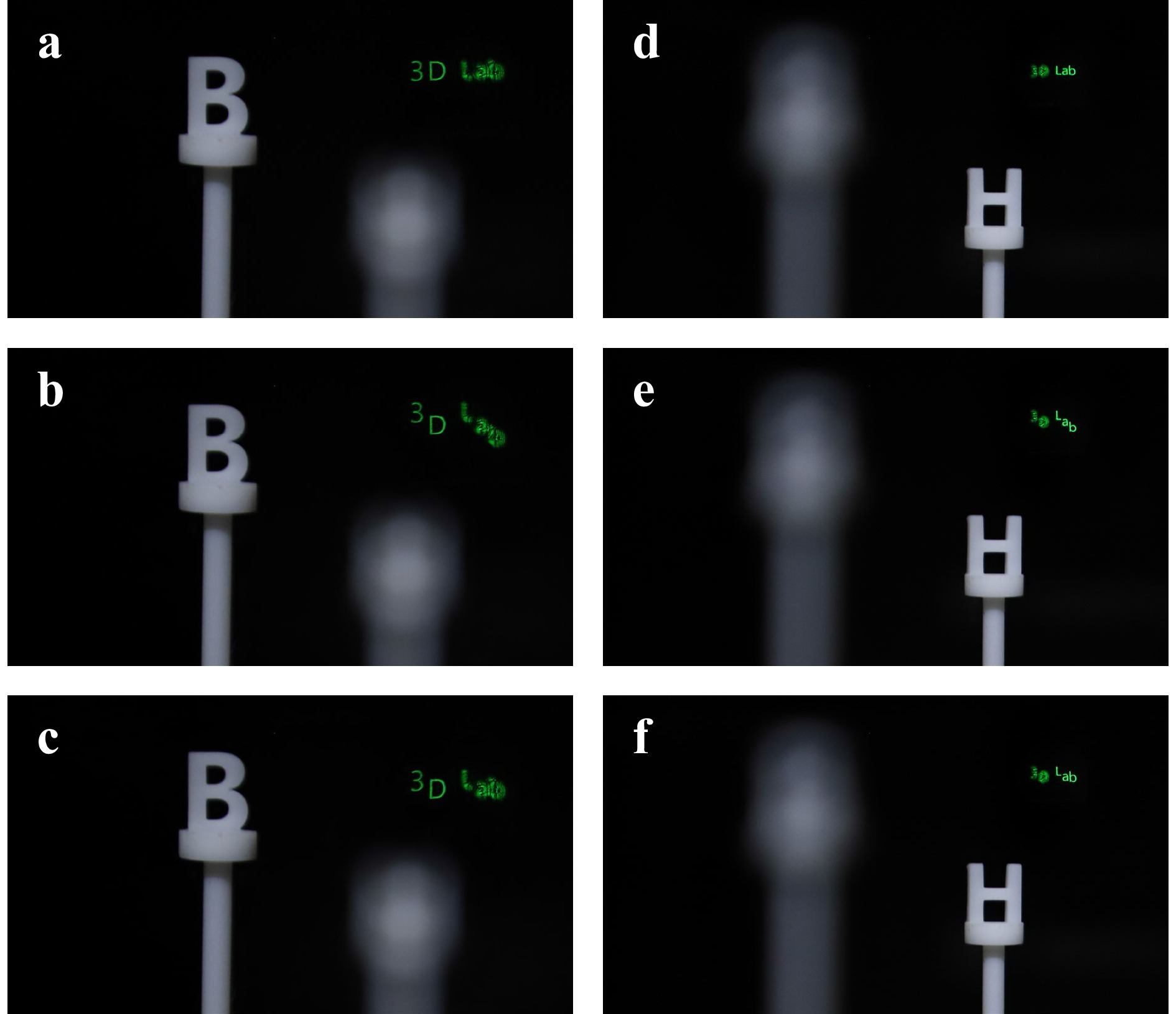
Fig. 10 Dynamic wide viewing reconstruction of 3D object. a–c Images at different moments focused on the ‘B’. d–f Images at different moments focused on the ‘H’.
-
Although many researchers have proposed the systems based on multiple SLMs stitching to expand the viewing angle of holographic 3D display, the calculation methods of the holograms are different. For example, in the circular holographic system37, each SLM is loaded with the holograms of objects from different perspectives, and the sum of all hologram sizes is equal to the size of the SLM array. In the tiled holographic system38, the size of the SLM array is equal to that of the hologram, but each SLM is loaded with a part of the hologram of the object. In the proposed system, we first consider the size of the object. The hologram of a single image point is analyzed based on the object size and the maximum diffraction angle of a single SLM, the required hologram size of a single image point is finally calculated according to Eq. 2. The size of the whole hologram is determined by Eq. 3, and it is not equal to that of the SLM array. The proposed method ensures that each image point reaches the maximum diffraction angle of the SLM. In addition, we further design a liquid crystal grating to achieve the large viewing angle holographic 3D display. Liquid crystal grating has a special structure, which can provide the secondary diffraction of the reconstructed image to realize the continuous expansion of holographic viewing angle. Thus, the viewing angle of the proposed system can be enlarged greatly. However, such a liquid crystal grating is not used in the traditional system. This is also the difference between the proposed system and the traditional systems.
Because holographic 3D display is based on the principles of interference and diffraction, it can record and reconstruct all wavefront information of the object. The hologram loaded on the SLM array is generated by the interference of the reference light and object light; thus, it contains the complete depth information of the object. By changing the reconstruction distance of the holographic image recorded on the hologram, we can view a clear holographic image at different positions. When liquid crystal grating is used to enlarge the viewing angle, the viewing angle of each secondary diffraction image remains the same. This is also the limitation of using liquid crystal grating to expand the viewing angle. Although the observer can see the reconstructed image within a large range when moving, if he want to observe the changes of the reconstructed image from different perspectives, it is necessary to control liquid crystal grating to modulate different holograms at each order, which is difficult to achieve. In the proposed system, we do not consider the application with eye tracking. We can perhaps combine eye tracking and time division multiplexing to further expand the viewing angle. In addition, we will also consider the perceptual characteristics of human eyes to further optimize the viewing experience.
The viewing angle of the reconstructed image is only ~8.2º when no voltage is applied to liquid crystal grating. It is impossible to capture the reconstructed image outside of this viewing angle. When an appropriate voltage is applied to liquid crystal grating, nine secondary diffraction images are generated, meaning that the viewing angle is enlarged by nine times. It should be noted that the diffraction order of liquid crystal grating is even higher than nine under other voltage conditions, but at this time, the light intensity of the diffraction order may be uneven, and even some intermediate orders may be missing. To ensure the display quality, the intensity of the secondary diffraction image should be uniform. After adjustment, we find that the display quality is acceptable under the experimental voltage condition.
Although we studied the holographic display method with large viewing angle before36, the diffraction of the image point did not reach the maximum diffraction angle of SLM during the calculation of a hologram. That is, for a single diffraction image, when the pixel size of SLM is 3.74 µm, although the diffraction angle of SLM is 8.2º, the viewing angle of a complete reconstructed image may not reach 8.2º. Compared with our previous method, the proposed system considers the effective viewing area of the reconstructed image so that the diffraction angle of each image point is extended to the maximum diffraction range of SLM. In this paper, we use two SLMs as an example to build the system to verify the advantages of the large-size hologram, but when the object size is large, the size of SLM array needs to be larger. In the aspect of structure design of liquid crystal grating, based on the designed large-size hologram, we propose a new structure of liquid crystal grating and realize the modulation of nine diffraction orders. Finally, the viewing angle of ~73.4º is realized, which is markedly larger than the traditional method. In Table 1, the proposed system is compared with the existing system, and the proposed system demonstrates obvious advantages.
System Pixel pitch Pixel Screen size Viewing angle Texas Instruments, DMD 5.4 μm 1920×1080 1.04 cm×0.58 cm ~5.6° Holoeye, 10 Megapixel SLM 3.74 μm 4160×2464 1.60 cm×0.94 cm ~8.2° System by Li et al.36 3.74 μm 3840×2160 1.45 cm×0.81 cm ~57.4° Proposed system 3.74 μm 7680×2160 2.9 cm×0.81 cm ~73.4° Table 1. Comparison of characteristics between the proposed system and other systems
In this paper, we focus on a single wavelength for the feasibility demonstration. However, for a full-color holographic display, the wavelength dispersion effect must be considered. Liquid crystal grating is spectrally dependent on a given wavelength. When the red (λ = 671 nm), green (λ = 532 nm), and blue (λ = 473 nm) laser beams simultaneously illuminate the SLM, the color reconstructed image is modulated by the second diffraction of liquid crystal grating. Under the same voltage conditions, the pitch of liquid crystal grating is different. Thus, a chromatic aberration exists, as shown in Fig. 11. However, this chromatic aberration can be eliminated by designing the structure of liquid crystal grating or adding a thin refractive lens39. For example, the chromatic aberration can be eliminated by designing liquid crystal gratings with different pitches and controlling the reconstructed images of three colors to be modulated by liquid crystal grating with corresponding pitches. Limited by the processing conditions, color holographic 3D display with a large viewing angle has not been realized yet. We will continue to study the color holographic 3D display technology with a large viewing angle and believe that this technology will definitely make a breakthrough in the future.
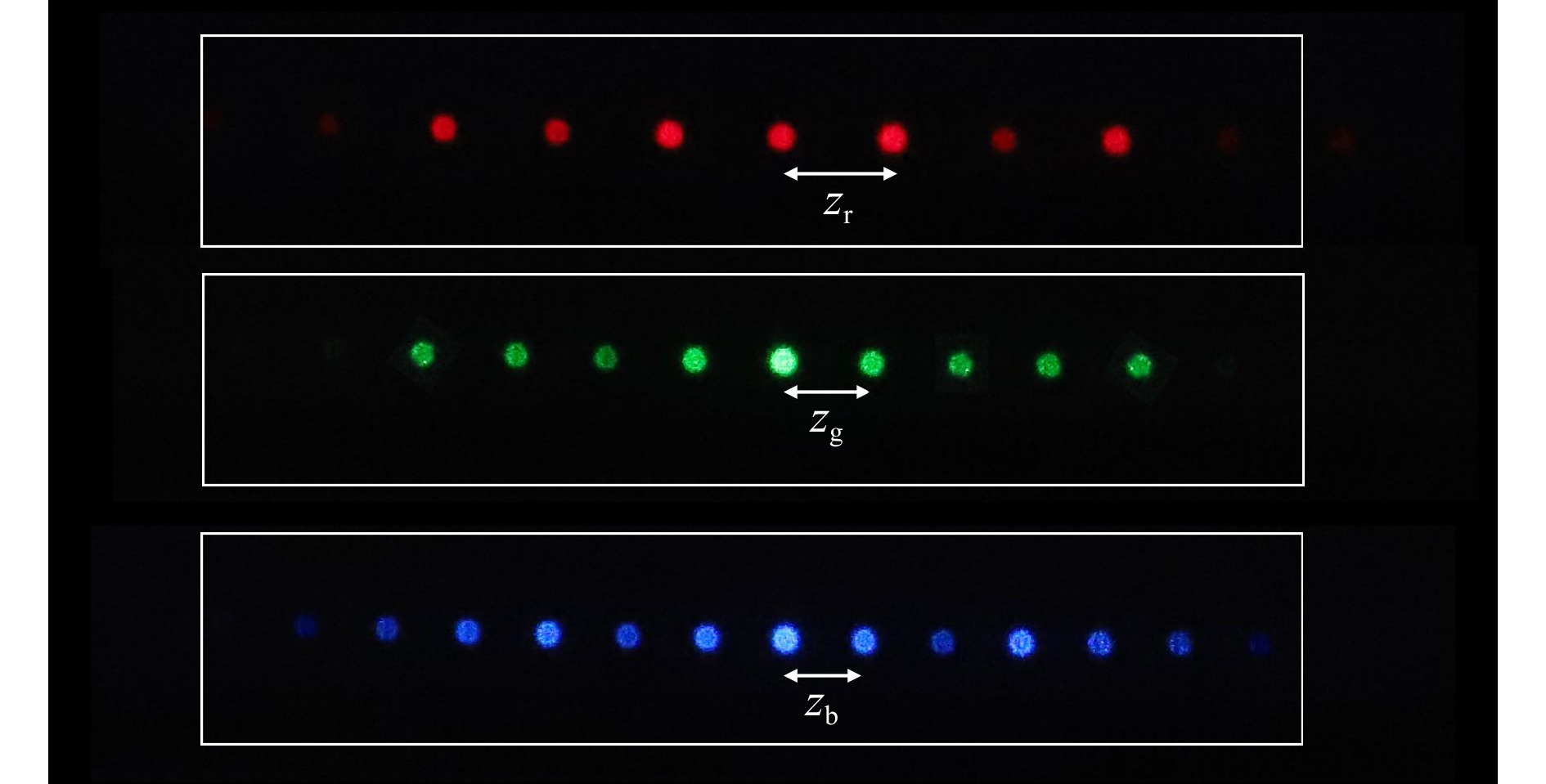
Fig. 11 Color chromatic aberration.
-
In conclusion, a large viewing angle holographic 3D display system is proposed. The core of the system comprises the SLMs on which a large-size hologram is loaded and liquid crystal grating. By assuming the maximum diffraction angle of the SLM as the limited diffraction modulation range of each image point, we could not only obtain the large-size hologram of the object, but also perform secondary diffraction modulation on the reconstructed image through the self-designed liquid crystal grating. The theoretical and experimental results demonstrate that the proposed system achieves a large viewing angle of 73.4°. The proposed system is expected to promote the applications of holographic 3D display.
-
This work is supported by the National Natural Science Foundation of China (62020106010, 62275009, U22A2079 and 11974258). We would like to thank Academic Excellence Foundation of BUAA for its support to PhD Students.
Large viewing angle holographic 3D display system based on maximum diffraction modulation
-
Di Wang1,
 ,
, - Nan-Nan Li1,
- Yi-Long Li1,
- Yi-Wei Zheng1,
- Zhong-Quan Nie2,
- Zhao-Song Li1,
-
Fan Chu1, *, ,
,
-
Qiong-Hua Wang1, *, ,
- Light: Advanced Manufacturing 4, Article number: 18 (2023)
- Received: 28 January 2023
- Revised: 20 June 2023
- Accepted: 22 June 2023 Published online: 20 July 2023
doi: https://doi.org/10.37188/lam.2023.018
Abstract: An ideal holographic 3D display should have the characteristics of large viewing angle, full color, and low speckle noise. However, the viewing angle of the holographic 3D display is usually limited by existing strategies, which vastly hinders its extensive application. In this paper, a large viewing angle holographic 3D display system based on maximum diffraction modulation is proposed. The core of the proposed system comprises the spatial light modulators (SLMs) and liquid crystal grating. We also present a new feasible scheme for the realization of large viewing angle holographic 3D display. This is achieved by considering the maximum diffraction angle of SLM as the limited diffraction modulation range of each image point. By doing so, we could not only give access to the maximum hologram size of the object, but also tune the reconstructed image of secondary diffraction by using a self-engineered liquid crystal grating. More importantly, the proposed maximum diffraction modulation scheme enables the viewing angle of the proposed system to be enlarged to 73.4°. The proposed system has huge application potential in the fields such as education, culture, and entertainment.
Research Summary
A novel holographic 3D display system with large viewing angle
Holographic 3D display is widely considered a promising candidate for the ultimate 3D display solution. However, the viewing angle of holographic 3D display is far from meeting the viewing needs by resorting to the existing strategies. Qiong-Hua Wang from Beihang University of China and colleagues now report a novel large viewing angle holographic 3D display system that enables a viewing angle of 73.4°. The core idea of the proposed system is to consider the maximum diffraction angle of SLM as the limited diffraction modulation range of each image point and implement a self-engineered liquid crystal grating. The proposed system has huge application potential in fields such as education, culture, and entertainment and is expected to promote the applications of holographic 3D display.
Rights and permissions
Open Access This article is licensed under a Creative Commons Attribution 4.0 International License, which permits use, sharing, adaptation, distribution and reproduction in any medium or format, as long as you give appropriate credit to the original author(s) and the source, provide a link to the Creative Commons license, and indicate if changes were made. The images or other third party material in this article are included in the article′s Creative Commons license, unless indicated otherwise in a credit line to the material. If material is not included in the article′s Creative Commons license and your intended use is not permitted by statutory regulation or exceeds the permitted use, you will need to obtain permission directly from the copyright holder. To view a copy of this license, visit http://creativecommons.org/licenses/by/4.0/.

 DownLoad: